 Products Home / Lasers / Coherent Sources / Single-Frequency Lasers / Low-Noise, Narrow-Linewidth Laser System, O-Band (1310 nm)
Low-Noise, Narrow-Linewidth Laser System, O-Band (1310 nm)
- High-Power, Turnkey, Single-Frequency Laser Systems at 1310 nm
- Low-Noise Drive Electronics to Minimize RIN and Linewidth
- 20 MHz Current Modulation Bandwidth
- Linewidths as Low as 150 Hz Available
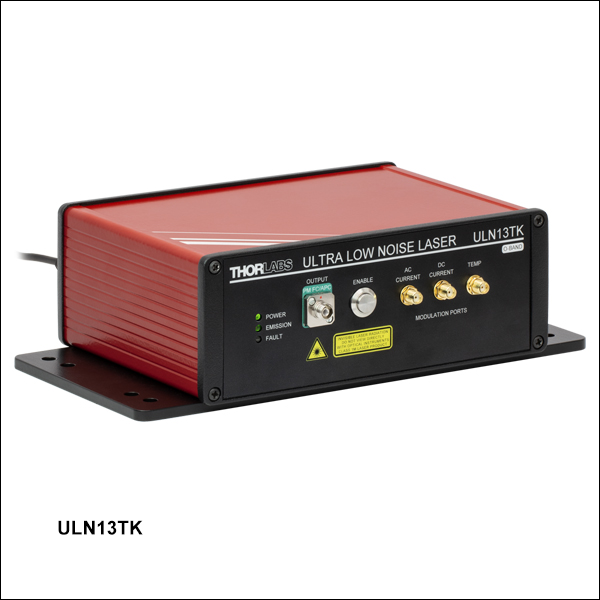
ULN13TK
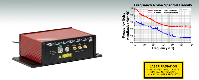
Narrow-Linewidth, Low-Noise Laser System, 1310 nm
The frequency noise spectral density gives a Lorentzian linewidth of 110 Hz for the ULN13TK Laser and 106 kHz for the DFB13TK Laser.


Please Wait
| Key Specification Comparison | ||
|---|---|---|
| Item # | ULN13TK | DFB13TK |
| Typical Linewidth | 150 Hz | 100 kHz |
| Typical RIN | -160 dBc/Hz | -150 dBc/Hz |
| Mode-Hop-Free Single-Frequency Operating Current Region |
Discontinuousa | Continuousb |
| Temperature Tuning Range | 0.32 nmc | 1.6 nmd |
| AC Current Modulation Depth | ±10 mA | ±50 mA |
| DC Current Modulation Depth | ±10 mA | ±10 mA |
Applications
- Optical Reference Laser
- LIDAR/LADAR
- Fiber Optic Sensing
- Quantum Optics
- Atomic Clocks
- Rubidium Cooling
- Coherent Communications
Features
- High-Power Turnkey Single-Frequency Laser Systems in the O-Band
- Ultra-Low-Noise (ULN), Narrow-Linewidth Laser System (US patents: 10193306, 10483718, 10476233, and 10454248):
- 150 Hz Typical Linewidth, 70 dB typical SMSR
- Relative Intensity Noise (RIN) of -160 dBc/Hz
- Discontinuous Mode-Hop-Free Regions 20 mA to 50 mA Wide
- Temperature Tuning Range of 0.32 nm with Simultaneous Current Tuning
- Distributed Feedback (DFB) Laser System:
- 100 kHz Typical Linewidth, 50 dB Typical Side-Mode Suppression Ratio (SMSR)
- RIN of -150 dBc/Hz
- Continuous Mode-Hop-Free Operating Current Region
- Temperature Tuning Range of 1.6 nm
- Low-Noise Drive Electronics to Minimize RIN and Linewidth
- Analog Modulation Inputs for DC Current, AC Current, and Laser Temperature
- Integrated Isolator to Minimize Effects of Back-Reflected Light
- Remote Operation and Set-Point Adjustment with Command-Line Interface via USB 2.0
Click to Enlarge
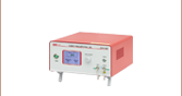
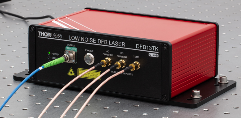
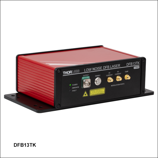
Figure 1.1 The DFB13TK and ULN13TK lasers can be mounted to an optical table using four 1/4"-20 cap screws. The DFB13TK is pictured with a P3-1310PM-FC-5 PM fiber patch cable and three CA2912 SMA cables, which are connected to the optical output and analog modulation ports, respectively.
Thorlabs' single-frequency, turnkey, low-noise laser systems at 1310 nm are ready-to-use laser systems that integrate a low-noise driver and temperature stabilization inside of a benchtop housing. To minimize the laser linewidth and relative intensity noise (RIN), these lasers include drive electronics that are designed to minimize the current noise. An isolator is integrated at the output of the lasers to minimize the impact of any back-reflected light on the lasers.
The ULN13TK is an ultra-low-noise (ULN) laser system based on a hybrid external-cavity semiconductor laser employing a fiber Bragg grating (FBG) for feedback to the laser cavity. This patented design enables exceptionally narrow Lorentzian linewidths of 150 Hz and the lowest available RIN of -160 dBc/Hz. When factory-set for optimized performance, this laser offers typical optical output powers of 120 mW with a side-mode suppression ratio (SMSR) of 70 dB. As a result of this unique design, the mode-hop-free single-frequency regions are not continuous as the laser current is adjusted, typically limited to 20 mA to 50 mA wide current regions. The temperature of the laser case is stabilized through a third temperature stabilization circuit to provide long-term power and wavelength stability when the system is used in standard laboratory environments.
While the center wavelength for Item # ULN13TK is listed as 1310 nm, this is only a typical number. The center wavelength of a particular unit varies from production run to production run, so the unit you receive may not operate at the typical center wavelength. By clicking "Choose Item" below, a list will appear that contains the center wavelength, output power, and operating current of each in-stock unit. Clicking on the red Docs Icon ( ) next to the serial number provides access to a PDF with serial-number-specific data and spectral characteristics.
The DFB13TK laser is based on a distributed feedback (DFB) diode, which incorporates a grating structure along the length of the gain medium of the laser chip, providing single-frequency emission with typical relative intensity noise (RIN) of -150 dBc/Hz and typical linewidths of 100 kHz. Factory-set for optimized performance, this laser offers a minimum output power of 100 mW with an SMSR of 50 dB. This design allows for a broad, mode-hop-free, single-frequency operation range (50 mA to 500 mA). The DFB13TK laser system can also be tuned by adjusting the current or the temperature of the laser chip, with a mode-hop-free temperature tuning range of up to 1.6 nm.
These lasers are designed with laser frequency locking applications in mind. The systems come equipped with two analog current modulation ports (DC and AC coupled) and an analog temperature modulation port. These modulation inputs can be used to lock the laser frequencies to optical cavities or referenced using servo electronics in order to build stable laser systems.
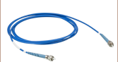
The optical outputs of these lasers are fiber-coupled via FC/APC bulkhead (2.0 mm narrow key) output connectors. For best performance, we recommend connecting our PM FC/APC fiber patch cables that contain PM1300-XP fiber, such as the P3-1310PM-FC-1 patch cable. Note that the polarization axis is aligned with the narrow key of the bulkhead connector.
The systems are powered by a 12 VDC, 4 A input. A DS12 power supply is provided with each laser; see the Shipping List tab for a complete list of items included with the device.
Thorlabs also offers the ULN15TK ultra-low-noise laser system at 1550 nm with typical linewidths of 100 Hz, as well as the DFB15TK low-noise DFB laser system.
Single-Frequency Operation and Wavelength Tuning
Factory-set for single-frequency operation, this laser has a preset drive current and temperature. When the laser is enabled using the push-button switch on the front panel (see Front & Back Panels tab), the laser operates at the preset current level. Each laser is shipped with a test data sheet taken at the preset operating conditions; click here for a sample data sheet. These datasheets can also be downloaded by clicking on the red Docs icon () next to the Item # and entering your device's serial number under "Download Serial Item Data."
The user can adjust the operating current either by sending a command through USB communication (see Remote Operation below) or by applying small modulation to the current through one of the modulation ports on the front panel of the system (see Analog Modulation below). Adjusting the operating current results in both a change in the output power but also a change in the laser wavelength. In addition to the operating current, the laser chip temperature is also adjustable either through the command-line interface (USB) or the front-panel modulation port. The temperature changes are primarily useful for tuning the laser wavelength while maintaining a relatively constant output power. See the Specs tab for more information on current and temperature tuning of these lasers.
Analog Modulation
By controlling the laser's drive current or temperature, the laser's wavelength can be tuned free of mode-hopping within a small range around its set-point. Three analog modulation ports (SMA Female) are included on the front panel (see the Front & Back Panels tab). Two of the ports allow the laser current to be modulated by ±10 mA around the current set point: of these, the port labelled "AC Current" can support modulation frequencies from 2 kHz to 20 MHz, and the port labelled "DC Current" accepts frequencies from DC to 10 MHz (Item # ULN13TK) or 5 MHz (Item # DFB13TK). The third port, which is labelled "Temp", controls the FBG temperature (Item # ULN13TK) or chip temperature (Item # DFB13TK) and accepts modulation frequencies from DC to 1 Hz. To see how the laser wavelength can be tuned around its set-point, please see the wavelength tuning plots provided in the Graphs tab.
Each modulation port accepts a -5 V to 5 V input signal. To convert the modulation voltage into a current or temperature change, see the Specs tab.

Reza Salem
BU Leader, Fiber Lasers

I look forward to hearing from you!
Committed to Your Success
I am happy to assist with questions concerning our single-frequency, low-noise, turnkey laser systems. If our catalog offerings do not meet your needs, these products can be customized using some of our DBR and DFB single-frequency laser devices that require a drive current ≤1 A. The following (wavelengths / incorporated laser) combinations are available for our turnkey laser systems:If you are interested in these laser systems, I invite you to contact us with your questions, comments, or requests.
Remote Operation
Remote operation is also possible by connecting the laser to a PC (not included) via the USB port on the back of the unit and using a command line interface. In addition to basic functions such as turning the laser on and off or reading status indicators, the command line enables the user to modify the laser operating set-points. The full list of commands can be found in the laser manual. A USB-AB-72 USB 2.0 Type-A to Mini-B Cable is included with each device.
Adjusting the laser parameters (operating current and temperature) can be used for tuning the laser power or wavelength. Typical performance plots that demonstrate the laser's center wavelength tuning and the single-mode operating regions can be found on the Graphs tab. Please note that specific performance data is provided on the datasheet shipped with each device.
A 9-Pin male D-Sub connector is also included on the back panel of the systems for RS-485 communication protocol. Please refer to the Pin Diagrams tab for the pin assignment of the connector.
Mounting
For mounting to an optical table, the compact housing of these benchtop lasers feature four clearance holes each for M6 or 1/4" cap screws.
| Item # | ULN13TK | DFB13TK |
|---|---|---|
| Laser Specificationsa | ||
| Center Wavelengthb | 1310 nm ± 15 nm | 1310 nm ± 5 nm |
| Output Powerc | >90 mW (Typ. 120 mW) | ≥100 mW |
| Linewidthd | <300 Hz (Typ. 150 Hz) | <200 kHz (Typ. 100 kHz) |
| Relative Intensity Noise (RIN)e | -160 dBc/Hz | -150 dBc/Hz |
| Side-Mode Suppression Ratio (SMSR) | >60 dB (Typ. 70 dB) | >35 dB (Typ. 50 dB) |
| Polarization Extinction Ratio (PER) | >18 dB | 25 dB |
| Output Isolation | >25 dB | 25 dB |
| Mode-Hop-Free Operating Current | N/A | 50 mA - 500 mA |
| Mode-Hop-Free Power Range | N/A | 15 mW - 100 mW |
| Slope Efficiency | - | 0.27 W/A |
| Threshold Current | 50 mA | 15 mA |
| Current Tuning Coefficient | 0.25 pm/mA | 0.003 nm/mA |
| FBG Temperature Tuning Coefficient | 8 pm/°C | N/A |
| FBG Temperature Tuning Range | 10 °C - 60 °C | N/A |
| Laser Chip Tuning Coefficient | - | 0.08 nm/°C |
| Laser Chip Temperature Tuning Range | - | 15 °C - 35 °C |
| Temperature Tuning Range | 0.32 nmf | 1.6 nmg |
| Fiber Specifications | ||
| Output Fiber Typeh | PM1300-XP | PM1300 |
| Output Fiber Connectors | FC/APC Compatible, 2.0 mm Narrow Key | |
| External Modulation Specifications | ||
| AC Voltage to Current Conversion Rate | 2 mA/V | 10 mA/V |
| DC Voltage to Current Conversion Rate | 2 mA/V | |
| Voltage to Temperature Conversion Rate | Firmware Adjustable (Default = 0.2 °C/V) | |
| Input Voltage Range (All Ports) | -5 V to 5 V | |
| Input Impedance (All Ports) | 1 kΩ | |
| AC Current Modulation Depth | ±10 mA | ±50 mA |
| DC Current Modulation Depth | ±10 mA | ±10 mA |
| AC Current Modulation Frequency Rangei | 2 kHz to 20 MHz | |
| DC Current Modulation Frequency Rangei | DC to 10 MHz | DC to 5 MHz |
| Temperature Modulation Frequency Range | DC to 1 Hz | |
| Absolute Maximum Ratings | ||
|---|---|---|
| Item # | ULN13TK | DFB13TK |
| Absolute Maximum Output Power | 145 mW | |
| Operating Temperature | 15 °C to 30 °C | 15 °C to 35 °C |
| Storage Temperature | -10 °C to 40 °C | |
| General Specifications | ||
|---|---|---|
| Item # | ULN13TK | DFB13TK |
| Input Voltage | 12 V (from DS12 Power Supply) | |
| Input Power | 20 W (Max) | |
| Dimensions (W x D x H) | 10.00" x 5.31" x 2.93" (254.0 mm x 135.0 mm x 74.4 mm) |
10.00" x 5.31" x 2.94" (254.0 mm x 135.0 mm x 74.6 mm) |
| Weight | 4.7 lbs (2.1 kg) | |
| Laser Class | 1M | |
Figures 3.1 and 3.2 represent the relative intensity noise (RIN) and frequency noise for the low-noise, single-frequency laser systems.
Click to Enlarge
Click Here for ULN13TK Data
Click Here for DFB13TK Data
Figure 3.2 Example frequency noise data for the ULN13TK and DFB13TK laser systems operated at the factory-set conditions.
Click to Enlarge
Click Here for ULN13TK Data
Click Here for DFB13TK Data
Figure 3.1 The typical low-frequency relative intensity noise (RIN) for a ULN13TK and DFB13TK laser system operated at the factory-set conditions.
Figures 3.3 through 3.5 represent the typical performance of the ULN13TK ultra-low-noise laser system. Specific performance data is provided on the datasheet shipped with each device; click here for a sample data sheet.
Click to Enlarge
Click Here for Data
Figure 3.3 The typical single mode operating regions for a ULN13TK laser system operated at a Fiber Bragg Grating temperature (TFBG) of 27 °C. Multimode regions have been removed.
Click to Enlarge
Click Here for Data
Figure 3.4 The center wavelength (λc) tuning with changes in the pump current and Fiber Bragg Grating temperature (TFBG). Multimode regions have been removed.
Click to Enlarge
Click Here for Data
Figure 3.5 The typical spectrum for a ULN13TK laser system operated at the factory-set conditions. This measurement was taken using an optical spectrum analyzer with a spectral resolution of 0.02 nm.
Figures 3.6 through 3.8 represent the typical performance of the DFB13TK low-noise laser system. Specific performance data is provided on the datasheet shipped with each device; click here for a sample data sheet.

Click to Enlarge
Click Here for Data
Figure 3.6 Example output power vs. current data for a DFB13TK laser system operated at factory-set conditions. The DC current set-point is adjustable up to 450 mA, while the AC modulation port can add up to 50 mA of additional current modulation for access to the entire 50 mA to 500 mA mode-hop-free operating current range.

Click to Enlarge
Click Here for Data
Figure 3.7 Example temperature and current tuning for a DFB13TK laser system operated at the factory-set conditions. The DC current set-point is adjustable up to 450 mA, while the AC modulation port can add up to 50 mA of additional current modulation for access to the entire 50 mA to 500 mA mode-hop-free operating current range.
Click to Enlarge
Click Here for Data
Figure 3.8 The typical spectrum for a DFB13TK laser system operated at the factory-set conditions. This measurement was taken using an optical spectrum analyzer with a spectral resolution of 0.02 nm.

Click to Enlarge
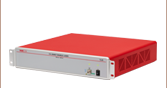
Figure 4.2 ULN13TK Turnkey ULN Laser Back Panel

Click to Enlarge
Figure 4.1 ULN13TK Turnkey ULN Laser Front Panel
| Front Panel | |
|---|---|
| Call Out | Description |
| 1 | Status Indicator LEDs |
| 2 | Laser Output Port (FC/APC, 2.0 mm Narrow Key, PM Fiber Output) |
| 3 | Laser Enable Push-Button Switch |
| 4 | AC Current Modulation Input (SMA Female) |
| 5 | DC Current Modulation Input (SMA Female) |
| 6 | Temperature Control Modulation Input (SMA Female) |
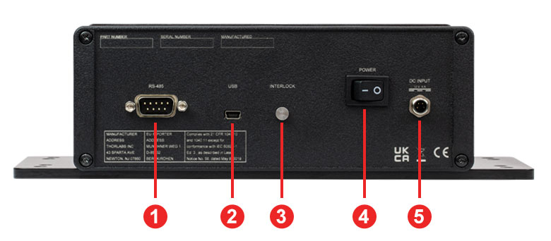
| Back Panel | |
|---|---|
| Call Out | Description |
| 1 | RS-485 Communication (DB-9 Male) |
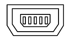
| 2 | USB Communication (USB Mini-B) |
| 3 | Remote Interlock Pin (2.5 mm Mono Phono Female) |
| 4 | Power Switch |
| 5 | DC Input (M8 Connector for the DS12 Power Supply) |
Click to Enlarge
Figure 4.4 DFB13TK Turnkey DFB Laser Back Panel
 Click to Enlarge
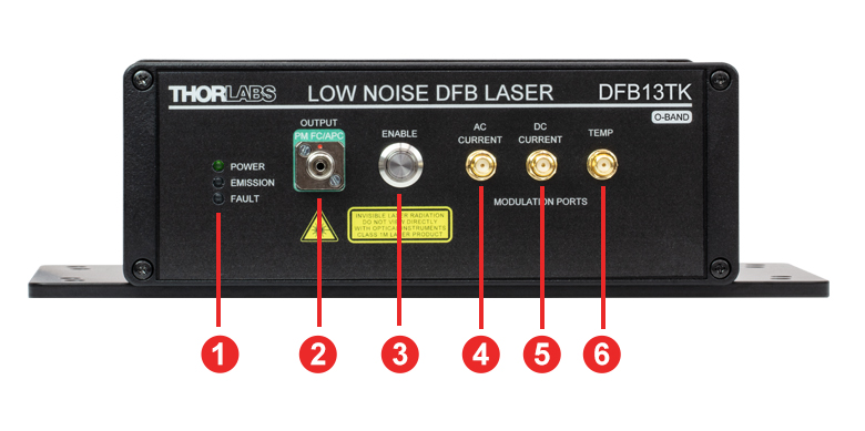
Figure 4.3 DFB13TK Turnkey DFB Laser Front Panel
| Front Panel | |
|---|---|
| Call Out | Description |
| 1 | Status Indicator LEDs |
| 2 | Laser Output Port (FC/APC, 2.0 mm Narrow Key, PM Fiber Output) |
| 3 | Laser Enable Push-Button Switch |
| 4 | AC Current Modulation Input (SMA Female) |
| 5 | DC Current Modulation Input (SMA Female) |
| 6 | Temperature Control Modulation Input (SMA Female) |
| Back Panel | |
|---|---|
| Call Out | Description |
| 1 | RS-485 Communication (DB-9 Male) |
| 2 | USB Communication (USB Mini-B) |
| 3 | Remote Interlock Pin (2.5 mm Mono Phono Female) |
| 4 | Power Switch |
| 5 | DC Input (M8 Connector for the DS12 Power Supply) |
ULN13TK Pin Diagrams
USB 2.0 Communication
USB Mini-B
Input for Analog Modulation
SMA Female

Input Voltage: -5 V to 5 V
Input Impedance: 1 kΩ
AC Current Modulation Frequency Range: 2 kHz to 20 MHz*
DC Current Modulation Frequency Range: DC to 10 MHz*
*The specified bandwidth refers to the 3 dB electrical bandwidth of the modulation circuits. The laser response has a slow roll-off for frequencies above 1 MHz.
RS-485 Communication
9-Pin Male D-Sub Connector 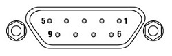
| Pin Assignment | |
|---|---|
| Pin | Output Signal |
| 1 | RS-485 Half-Duplex T/R+ |
| 2 | RS-485 Half-Duplex T/R- |
| 3 | Not Connected |
| 4 | Not Connected |
| 5 | Ground |
| 6 | Not Connected |
| 7 | Ground |
| 8a | Do Not Connect |
| 9a | Do Not Connect |
DFB13TK Pin Diagrams
USB 2.0 Communication
USB Mini-B
Input for Analog Modulation
SMA Female
Input Voltage: -5 V to 5 V
Input Impedance: 1 kΩ
AC Current Modulation Frequency Range: 2 kHz to 20 MHz*
DC Current Modulation Frequency Range: DC to 5 MHz*
*The specified bandwidth refers to the 3 dB electrical bandwidth of the modulation circuits. The laser response has a slow roll-off for frequencies above 1 MHz.
RS-485 Communication
9-Pin Male D-Sub Connector 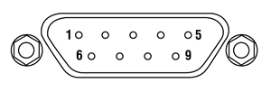
| Pin Assignment | |
|---|---|
| Pin | Output Signal |
| 1 | RS-485 Half-Duplex T/R+ |
| 2 | RS-485 Half-Duplex T/R- |
| 3 | Not Connected |
| 4 | Not Connected |
| 5 | Ground |
| 6 | Not Connected |
| 7 | Ground |
| 8a | Do Not Connect |
| 9a | Do Not Connect |
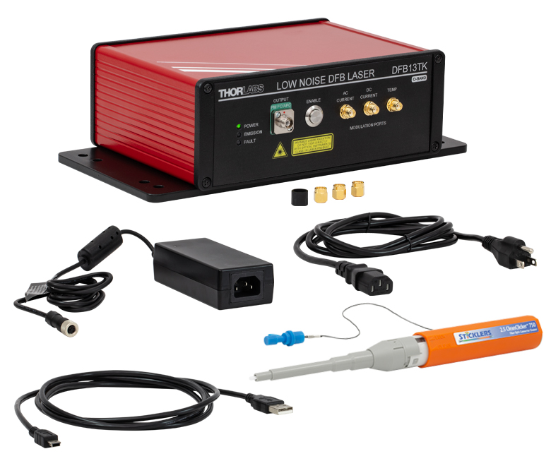
Click to Enlarge
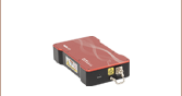
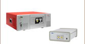
Figure 6.1 DFB13TK Laser System and Accessories
The ULN13TK Turnkey Ultra-Low-Noise (ULN) Laser System ships with the following components:
Click for Details
Figure 7.1 Experimental Setup for Laser Stabilization
Laser Stabilization
The ULN13TK and DFB13TK turnkey, low noise laser systems offer exceptional optical spectral purity and are configured for out-of-the-box use with minimal setup effort. However, for the most demanding applications, such as optical clocks and high-resolution spectroscopy, active electronic feedback may be required to further suppress technical noise and drifts. These turnkey lasers conveniently provide multiple high-bandwidth analog modulation ports for locking to external optical references such as an optical cavity or an atomic/molecular transition.
In Figure 7.1, we show an example of how the Pound-Drever-Hall (PDH) locking scheme is used to lock the DFB13TK laser to a reference cavity comprised of mirrors with a crystalline coating attached to an ultra-low expansion glass spacer. The RF modulation input conveniently permits the PDH sidebands to be generated without an external optical modulator. Demodulation of the reflected signal from the cavity yields an error signal which can be processed with a servo filter to maintain resonance with the optical cavity. This turnkey laser provides a high-bandwidth DC-coupled current modulation port to correct for fast fluctuations, and a slower temperature modulation port with larger range to correct for slower drifts.
ECL, DFB, VHG-Stabilized, DBR, and Hybrid Single-Frequency Lasers

Click to Enlarge
Figure 8.1 ECL Lasers have a Grating Outside of the Gain Chip
A wide variety of applications require tunable single-frequency operation of a laser system. In the world of diode lasers, there are currently four main configurations to obtain a single-frequency output: external cavity laser (ECL), distributed feedback (DFB), volume holographic grating (VHG), and distributed Bragg reflector (DBR). All four are capable of single-frequency output through the utilization of grating feedback. In addition, an ECL can be combined with a fiber Bragg grating (FBG) to create a hybrid design. However, each type of laser uses a different grating feedback configuration, which influences performance characteristics such as output power, tuning range, and side mode suppression ratio (SMSR). We discuss below some of the main differences between single-frequency diode lasers.
External Cavity Laser
The External Cavity Laser (ECL) is a versatile configuration that is compatible with most standard free space diode lasers. This means that the ECL can be used at a variety of wavelengths, dependent upon the internal laser diode gain element. A lens collimates the output of the diode, which is then incident upon a grating (see Figure 8.1). The grating provides optical feedback and is used to select the stabilized output wavelength. With proper optical design, the external cavity allows only a single longitudinal mode to lase, providing single-frequency laser output with high side mode suppression ratio (SMSR > 45 dB).
One of the main advantages of the ECL is that the relatively long cavity provides extremely narrow linewidths (<1 MHz). Additionally, since it can incorporate a variety of laser diodes, it remains one of the few configurations that can provide narrow linewidth emission at blue or red wavelengths. The ECL can have a large tuning range (>100 nm) but is often prone to mode hops, which are very dependent on the ECL's mechanical design as well as the quality of the antireflection (AR) coating on the laser diode.
Click to Enlarge
Figure 8.2 DFB Lasers Have a Bragg Reflector Along the Length of the Active Gain Medium
Distributed Feedback Laser
The Distributed Feedback (DFB) Laser (available in NIR and MIR) incorporates the grating within the laser diode structure itself (see Figure 8.2). This corrugated periodic structure coupled closely to the active region acts as a Bragg reflector, selecting a single longitudinal mode as the lasing mode. If the active region has enough gain at frequencies near the Bragg frequency, an end reflector is unnecessary, relying instead upon the Bragg reflector for all optical feedback and mode selection. Due to this “built-in” selection, a DFB can achieve single-frequency operation over broad temperature and current ranges. To aid in mode selection and improve manufacturing yield, DFB lasers often utilize a phase shift section within the diode structure as well.
The lasing wavelength for a DFB is approximately equal to the Bragg wavelength:

where λ is the wavelength, neff is the effective refractive index, and Λ is the grating period. By changing the effective index, the lasing wavelength can be tuned. This is accomplished through temperature and current tuning of the DFB.
The DFB has a relatively narrow tuning range: about 2 nm at 850 nm, about 4 nm at 1550 nm, or at least 1 cm-1 in the mid-IR (4.00 - 11.00 µm). However, over this tuning range, the DFB can achieve single-frequency operation, which means that this is a continuous tuning range without mode hops. Because of this feature, DFBs have become a popular and majority choice for real-world applications such as telecom and sensors. Since the cavity length of a DFB is rather short, the linewidths are typically in the 1 MHz to 10 MHz range. Additionally, the close coupling between the grating structure and the active region results in lower maximum output power compared to ECL and DBR lasers.
Click to Enlarge
Figure 8.3 VHG Lasers have a Volume Holographic Grating Outside of the Active Gain Medium
Volume-Holographic-Grating-Stabilized Laser
A Volume-Holographic-Grating-(VHG)-Stabilized Laser also uses a Bragg reflector, but in this case a transmission grating is placed in front of the laser diode output (see Figure 8.3). Since the grating is not part of the laser diode structure, it can be thermally decoupled from the laser diode, improving the wavelength stability of the device. The grating typically consists of a piece of photorefractive material (typically glass) which has a periodic variation in the index of refraction. Only the wavelength of light that satisfies the Bragg condition for the grating is reflected back into the laser cavity, which results in a laser with extremely wavelength-stable emission. A VHG-Stabilized laser can produce output with a similar linewidth to a DFB laser at higher powers that is wavelength-locked over a wide range of currents and temperatures.
Click to Enlarge
Figure 8.4 DBR Lasers have a Bragg Reflector Outside of the Active Gain Medium
Distributed Bragg Reflector Laser
Similar to DFBs, Distributed Bragg Reflector (DBR) Lasers incorporate an internal grating structure. However, whereas DFB lasers incorporate the grating structure continuously along the active region (gain region), DBR lasers place the grating structure(s) outside this region (see Figure 8.4). In general a DBR can incorporate various regions not typically found in a DFB that yield greater control and tuning range. For instance, a multiple-electrode DBR laser can include a phase-controlled region that allows the user to independently tune the phase apart from the grating period and laser diode current. When utilized together, the DBR can provide single-frequency operation over a broad tuning range. For example, high end sample-grating DBR lasers can have a tuning range as large as 30 - 40 nm. Unlike the DFB, the output is not mode hop free; hence, careful control of all inputs and temperature must be maintained.
In contrast to the complicated control structure for the multiple-electrode DBR, a simplified version of the DBR is engineered with just one electrode. This single-electrode DBR eliminates the complications of grating and phase control at the cost of tuning range. For this architecture type, the tuning range is similar to a DFB laser but will mode hop as a function of the applied current and temperature. Despite the disadvantage of mode hops, the single-electrode DBR does provide some advantages over its DFB cousin, namely higher output power because the grating is not continuous along the length of the device. Both DBR and DFB lasers have similar laser linewidths. Currently, Thorlabs offers only single-electrode DBR lasers.
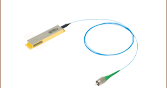
Ultra-Low-Noise Hybrid Laser
Thorlabs Ultra-Low-Noise (ULN) Hybrid Lasers each consist of a single angled facet (SAF) gain chip coupled to an exceptionally long fiber Bragg grating (FBG). They are designed to create a laser cavity, similar to an ECL, through the length of fiber. This cavity provides the ULN hybrid laser with a very narrow line width on the order of 100 Hz and low relative intensity noise of -165 dBc/Hz (typical). The FBG reflects a portion of the light emitted from the gain medium while remaining thermally isolated from it. The grating period can be changed by introducing thermal stress to the fiber, allowing users to temperature tune the laser output while being able to independently stabilize the gain medium's temperature. Because the laser's configuration provides excellent low-noise performance, it is likely the laser will not be the limiting factor at low-noise levels. It is critical to monitor the laser's environment to limit external noise contributions like acoustic and seismic vibrations, as well as driving the laser with a low-noise current source.

Click to Enlarge
Figure 8.5 Thorlabs Hybrid Lasers have a Fiber Bragg Grating Coupled to the Active Gain Medium
Conclusion
ECL, DFB, VHG, DBR, and hybrid laser diodes provide single-frequency operation over their designed tuning range. The ECL can be designed for a larger selection of wavelengths than either the DFB or DBR. While prone to mode hops, it provides narrow linewidths (<1 MHz). In appropriately designed instruments, ECLs can also provide extremely broad tuning ranges (>100 nm).
The DFB laser is the most stable single-frequency, tunable laser configuration. It can provide mode-hop-free performance over its entire tuning range (<5 nm), making it one of the most popular forms of single-frequency laser for much of industry. It has the lowest output power due to inherent properties of the continuous grating feedback structure.
The VHG laser provides stable wavelength performance over a range of temperatures and currents and can provide higher powers than are typical in DFB lasers. This stability makes it excellent for use in OEM applications.
The single-electrode DBR laser provides similar linewidth and tuning range as the DFB (<5 nm). However, the single-electrode DBR will have periodic mode hops in its tuning curve.
Hybrid lasers can be used to achieve extremely low-noise signals. In order to take advantage of this characteristic, the laser must be isolated from unwanted noise sources, such as acoustic and seismic vibrations and drive current noise.
| Posted Comments: | |
| No Comments Posted |

 Zoom
Zoom Click to Enlarge
Click for Data
Figure G1.1 This graph shows the typical single mode operating regions for a ULN13TK laser system operated at a fiber Bragg grating temperature (TFBG) of 30 °C. Multimode regions have been removed.
- 150 Hz Typical Lorentzian Linewidth
- -160 dBc/Hz Typical Relative Intensity Noise (RIN)
- 70 dB Typical Side-Mode Suppression Ratio (SMSR)
- 120 mW Typical Output Power
Thorlabs' ULN13TK Turnkey, Ultra-Low-Noise (ULN) Laser System is a ready-to-use laser system that integrates a patented fiber Bragg grating (FBG) based design, with a low-noise driver and temperature stabilization inside of a benchtop housing. The temperature of the laser case is stabilized through a third temperature stabilization circuit to provide long-term power and wavelength stability when the system is used in standard laboratory environments. See the blue info icon (![]() ) in Table G1.2 for typical performance specifications. Specific wavelengths within the center wavelength range are available upon request.
) in Table G1.2 for typical performance specifications. Specific wavelengths within the center wavelength range are available upon request.
The ULN13TK laser system provides exceptionally narrow Lorentzian linewidth (typ. 150 Hz) and the lowest available RIN (typ. -160 dBc/Hz) for applications that require demanding noise performance. The ULN design is based on a hybrid external-cavity semiconductor laser employing a fiber Bragg grating (FBG) for feedback to the laser cavity. As a result, the mode-hop-free single-frequency regions of the ULN are not continuous as the laser current is adjusted. Each mode-hop-free single-frequency region is typically limited to 20 mA to 50 mA of drive current (see Figure G1.1). The ULN wavelength can be adjusted via both current adjustment of the chip and temperature adjustment of the FBG. In order to maintain single-frequency operation as the temperature is tuned over a broad range, the laser current needs to be adjusted simultaneously.
The system comes equipped with two analog current modulation ports (AC and DC coupled) and an analog temperature modulation port, which can be used to lock the laser frequency to optical cavities or a reference using servo electronics in order to build stable laser systems. Remote operation is possible by connecting the laser to a PC and using a command line interface.
The optical output of this laser is fiber-coupled via an FC/APC bulkhead (2.0 mm narrow key) output connector. For best performance, we recommend connecting our PM FC/APC fiber patch cables that contain PM1300-XP fiber. Each laser is shipped with a DS12 power supply; see the Shipping List tab for a complete list of items included with the device.
Specific wavelengths within the center wavelength range are available upon request. Please contact Tech Sales for more information.
| Table G1.2 Specifications | ||||||||
|---|---|---|---|---|---|---|---|---|
| Item #a | Info | Center Wavelength | Output Powerb |
Linewidthc | Relative Intensity Noise (RIN)d |
Side-Mode Suppression Ratio (SMSR) |
Mode-Hop-Free Single-Frequency Region |
Temperature Tuning Range |
| ULN13TK | 1310 nm ± 15 nm | >90 mW | 150 Hz Typical, 300 Hz Max |
-160 dBc/Hz | >60 dB (Typ. 70 dB) | Discontinuouse | 0.32 nmf | |

 Zoom
Zoom
Click to Enlarge
Click Here for Data
Figure G2.1 Example temperature and current tuning for a DFB13TK laser system operated at the factory-set conditions.
- 100 kHz Typical Lorentzian Linewidth
- -150 dBc/Hz Typical Relative Intensity Noise (RIN)
- Continuous Mode-Hop-Free Single Frequency Operation
- 1.6 nm Temperature Tuning Range
Thorlabs' DFB13TK Turnkey, Low-Noise Distributed Feedback (DFB) Laser System is a ready-to-use laser system that integrates a 1310 nm DFB laser with a low-noise driver inside of a benchtop housing. See the blue info icon (![]() ) in Table G2.2 for typical performance specifications. Each DFB laser system is serialized and ships with individual test data; click here for a sample data sheet. These datasheets can also be downloaded by clicking on the red Docs icon () next to the Item # and entering your device's serial number under "Download Serial Item Data."
) in Table G2.2 for typical performance specifications. Each DFB laser system is serialized and ships with individual test data; click here for a sample data sheet. These datasheets can also be downloaded by clicking on the red Docs icon () next to the Item # and entering your device's serial number under "Download Serial Item Data."
The DFB design allows a broad mode-hop-free single-frequency operation region (50 mA to 500 mA), while maintaining a narrow 100 kHz Lorentzian linewidth and a typical relative intensity noise (RIN) of -150 dBc/Hz. Wavelength tuning can be accomplished by adjusting the current or the temperature of the laser chip, with typical temperature tuning of up to 1.6 nm (with the chip temperature adjusted by 20 °C). The DFB13TK will remain single-frequency as the temperature is tuned without the need to simultaneously adjust the current.
The system comes equipped with two analog current modulation ports (AC and DC coupled) and an analog temperature modulation port, which can be used to lock the laser frequency to optical cavities or referenced using servo electronics in order to build stable laser systems. Remote operation is possible by connecting the laser to a PC and using a command line interface.
The optical output of this laser is fiber-coupled via an FC/APC bulkhead (2.0 mm narrow key) output connector. For best performance, we recommend connecting our PM FC/APC fiber patch cables that contain PM1300-XP fiber. Each laser is shipped with a DS12 power supply; see the Shipping List tab for a complete list of items included with the device.
| Table G2.2 Specifications | ||||||||
|---|---|---|---|---|---|---|---|---|
| Item # | Info | Center Wavelength | Output Powera |
Linewidthb | Relative Intensity Noise (RIN)c |
Side-Mode Suppression Ratio (SMSR) |
Mode-Hop-Free Single-Frequency Region |
Temperature Tuning Range |
| DFB13TK | 1310 nm ± 5 nm | ≥100 mW | 100 kHz Typical, 200 kHz Max |
-150 dBc/Hz | >35 dB (Typ. 50 dB) | Continuousd | 1.6 nme | |