 Products Home
Turnkey MIR Laser Systems

- Plug-and-Play Benchtop Laser Systems
- Fabry-Perot (4.00 µm, 4.55 µm, or 10.5 µm) or Distributed Feedback (4 - 5 µm or 9 - 10 µm)
- Collimated CW Output
- Each System Includes a Laser Head & Touchscreen Controller
MLQF4550
4.55 µm CWL, 250 mW
Fabry-Perot Laser


Please Wait

Click to Enlarge
Touchscreen Controller Interface
Each turnkey MIR laser system includes a touchscreen controller that provides easy access to all laser parameters. More details are given in the Controller Interface tab.
| MIR Laser Types | |
|---|---|
| Fabry-Perot | TO Can |
| Two-Tab C-Mount | |
| D-Mount | |
| HHL | |
| Turnkey | |
| Distributed Feedback |
Two-Tab C-Mount |
| D-Mount | |
| HHL | |
| Turnkey | |
Click to Enlarge
Fabry-Perot and Distributed Feedback Laser Comparison
Fabry-Perot (FP) Lasers have broadband emission, while Distributed Feedback (DFB) Lasers emit at a well defined wavelength.
Turnkey Quantum Cascade Lasers (QCL)
- Fabry-Perot Lasers Offered from Stock:
- 4.00 µm, 4.55 µm, or 10.5 µm Center Wavelength (CWL)
- Minimum Output Power:
- MLQF4000 and MLQF4550: 250 mW
- MLQF10500: 200 mW
- Broadband Emission
- Distributed Feedback (DFB) Lasers Offered from Stock:
- Single-Frequency CWLs from 4 - 5 µm and 9 - 10 µm
- Typical Output Power:
- MLQD4500: 40 mW
- MLQD9500: 30 mW
- CWL Tunable Over a 1 to 5 cm-1 Range (See Item-Specific Data Sheets)
- Fabry-Perot & DFB Lasers from 3 to 12 µm Available Made-to-Order (See Graph Below)
- Easy-to-Use Touchscreen Controller
- Internal and External Modulation at up to 100 kHz
- Integrated Interlock Circuit and Hand-Operated Shutter
- Higher Output Powers Available by Contacting Tech Support
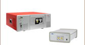
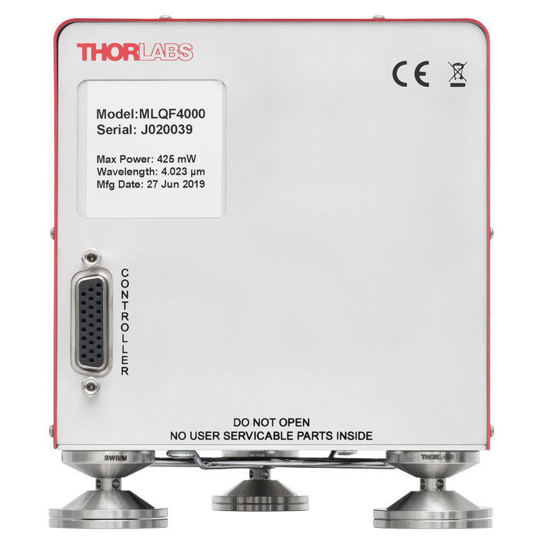
Thorlabs' Turnkey MIR Lasers are ready-to-use, ultra-low-maintenance laser systems that provide collimated CW output in the MIR. Each laser system consists of a single-spatial-mode quantum cascade laser head that is operated by a touchscreen current / temperature controller with a 4.3" LCD. Using the same automated test stations that qualify our packaged MIR laser chips, we measure the wavelength and L-I-V characteristics of each laser head at the factory, then store the test results on an EEPROM inside the laser head enclosure. This EEPROM allows the controller to automatically adjust itself for calibrated plug-and-play operation.
In general, Fabry-Perot lasers offer higher power and broadband emission, while DFB lasers provide single-wavelength emission that can be tuned over a 1 to 5 cm-1 range, depending upon the chip (see the Specs tab). Fabry-Perot lasers available from stock emit at either a 4.00 µm, 4.55 µm, or 10.5 µm CWL with a minimum output power of 250 mW for the MLQF4000 and MLQF4550 lasers or 200 mW for the MLQF10500 laser. Stocked DFB lasers feature a CWL within either the 4 - 5 µm or 9 - 10 µm range, and this emission wavelength is temperature- and current-tunable over a narrow range that varies for each device. Item-specific information such as the factory-measured spectrum, output power, and beam profile of each stocked item is available by clicking "Choose Item" below. Additionally, custom Fabry-Perot and DFB lasers at CWLs from 3 to 12 µm (refer to the graph below) are available by contacting Tech Support.
Click to Enlarge
Wavelengths Available as Custom Orders
Custom turnkey MIR lasers are available with typical lead times of 12 to 14 weeks. In the past, we have manufactured lasers at all of the wavelengths shown above. Please contact us with inquiries.
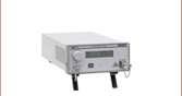
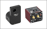
Touchscreen Controller
The controller enables local and remote control of the laser's optical output. A resistive touch screen allows for the screen to be operated when using gloves or other protective equipment. Screenshots of the interface are available in the Controller Interface tab. The back of the controller includes three SMA connectors: an external modulation input for sine, triangle, or square waves; an external tuning input for fine tuning DFB lasers to a spectral absorption line and locking the wavelength using error signal feedback; and a TTL synchronization output. A 2.5 mm mono jack is included for interlock connections, and a 4 mm banana jack is included for use with a ground pin. In addition, a USB 2.0 mini B connector allows remote operation using software written by the user in C, C++, C#, LabVIEW®, LabWindows™/CVI, or Visual Studio.
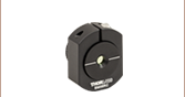
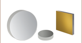
Air-Cooled Laser Head
The laser head contains the laser chip and a collimating aspheric lens. The only connection between the laser head and controller is made through the included HD DB26 cable. A built-in thermistor and thermoelectric cooler (TEC) allow the controller to set and actively regulate the laser chip's temperature, while an automatic over-temperature shutoff protects the laser from thermal damage. No chiller lines are required.
Three SWB/M Mounting Feet provide a nominal beam height of 67.0 mm. These individually adjustable feet allow for coarse beam height adjustment over a ±10.0 mm range and contain swivel joints, allowing the beam pointing to be adjusted while keeping the laser level with the optical table. When the mounting feet are locked down by a clamping fork, the angle of each foot becomes fixed. Three CF175 Clamping Forks are included with the laser head.
When installing the laser system, note that air vents are located on the top, sides, and bottom of the laser head, so it is necessary to leave adequate room near the vents for air circulation. The laser head should not be operated while the mounting feet are removed.
Fabry-Perot Laser Heads
| Optical Specifications | ||||||||||
|---|---|---|---|---|---|---|---|---|---|---|
| Item # | MLQF4000 | MLQF4550 | MLQF10500 | |||||||
| Characteristic | Minimum | Typical | Maximum | Minimum | Typical | Maximum | Minimum | Typical | Maximum | |
| Center Wavelength | 3.90 µm | 4.00 µm | 4.10 µm | 4.45 µm | 4.55 µm | 4.65 µm | 10.0 µm | 10.5 µm | 11.5 µm | |
| Optical Output Powera | 250 mW | - | <500 mWb | 250 mW | - | <500 mWb | 200 mW | - | <500 mWb | |
| Spectral Bandwidth (5 - 95% Integrated Power) |
- | 130 nm | - | - | 130 nm | - | - | 300 nm | - | |
| Beam Pointing | Horizontal | -0.3° | 0° | +0.3° | -0.3° | 0° | +0.3° | -0.3° | 0° | 0.3° |
| Verticalc | -0.3° | 0° | +0.3° | -0.3° | 0° | +0.3° | -0.3° | 0° | 0.3° | |
| Beam Divergenced | Horizontal | - | 3.5 mrad | - | - | 3.5 mrad | - | - | 6 mrad | - |
| Vertical | - | 3.0 mrad | - | - | 3.0 mrad | - | - | 6 mrad | - | |
| M2 (See Footnote a) | Horizontal | 1 | - | 1.3 | 1 | - | 1.3 | 1 | 1.1 | 1.3 |
| Vertical | 1 | - | 1.3 | 1 | - | 1.3 | 1 | 1.1 | 1.3 | |
| Sample Beam Profile (Click to Enlarge) |  |
 |
 |
|||||||
| Sample L-I-V Curve (Click to Enlarge) |  |
 |
 |
|||||||
| Output Power Stability over Operating Temperature Rangee (+15 to +35 °C) |
-3% | - | +3% | -3% | - | +3% | -3% | - | +3% | |
| Output Power Stability over 24 Hours at Room Temperature |
-2.5% | - | +2.5% | -2.5% | - | +2.5% | -2.5% | - | 2.5% | |
| Laser Current | - | - | 1.2 A | - | - | 1.2 A | - | - | 1.2 A | |
| Physical Specifications | |
|---|---|
| Dimensions (W x H x D) | 114.0 mm x 132.8 mm x 208.4 mm (4.49" x 5.23" x 8.21") |
| Operating Temperature Rangea | +15 to +35 °C, Non-Condensing |
| Storage Temperature Range | 0 to +50 °C, Non-Condensing |
| Weight of Laser Head | 2.1 kg (4.6 lbs) |
| Laser Class | 3B (Output Power <500 mW) |

Click to Enlarge
This sample spectrum is measured at 25 °C. Each device has a unique spectrum. To get the spectrum of a specific, serial-numbered device, click "Choose Item" below, then click on the Docs Icon next to the serial number. If you need spectral characteristics different than those shown, please contact Tech Support to inquire about a custom laser.
Distributed-Feedback (DFB) Laser Head
| Optical Specifications | |||||||
|---|---|---|---|---|---|---|---|
| Item # | MLQD4500 | MLQD9500 | |||||
| Characteristic | Minimum | Typical | Maximum | Minimum | Typical | Maximum | |
| Center Wavelength | 4.00 µm | - | 5.00 µm | 9.00 µm | - | 10.00 µm | |
| Optical Output Powera | 5 mW | 40 mW | - | 5 mW | 30 mW | - | |
| Side Mode Supression Ratio (SMSR) | 20 dB | - | - | 20 dB | - | - | |
| Beam Pointing | Horizontal | -0.3° | 0° | +0.3° | -0.3° | 0° | +0.3° |
| Verticalb | -0.3° | 0° | +0.3° | -0.3° | 0° | +0.3° | |
| Beam Divergencec | Horizontal | - | 3.5 mrad | - | - | 6 mrad | - |
| Vertical | - | 3.0 mrad | - | - | 6 mrad | - | |
| M2 (See Footnote a) | Horizontal | 1 | - | 1.3 | 1 | 1.1 | 1.3 |
| Vertical | 1 | - | 1.3 | 1 | 1.1 | 1.3 | |
| Sample Beam Profile (Click to Enlarge) |  |
 |
|||||
| Sample L-I-V Curve (Click to Enlarge) |  |
 |
|||||
| Sample Spectrum (Click to Enlarge) |  |
 |
|||||
| Sample Wavelength Tuning (Click to Enlarge) |  |
 |
|||||
| Output Power Stability over Operating Temperature Ranged (+15 to +35 °C) |
- | ±3% | - | - | ±3% | - | |
| Output Power Stability over 24 Hours at Room Temperature | - | ±2.5% | - | - | ±2.5% | - | |
| Output Wavelength Stability over Operating Temperature Rangee (+15 to +35 °C) |
- | 0.125 cm-1 (0.25 nm) |
- | - | - | 0.125 cm-1 (1.2 nm) |
|
| Physical Specifications | |
|---|---|
| Dimensions (W x H x D) | 114.0 mm x 132.8 mm x 208.4 mm (4.49" x 5.23" x 8.21") |
| Operating Temperature Rangea | +15 to +35 °C, Non-Condensing |
| Storage Temperature Range | 0 to +50 °C, Non-Condensing |
| Weight of Laser Head | 2.1 kg (4.6 lbs) |
| Laser Class | 3B (Output Power <500 mW) |
MLSC Laser Controller
| Laser Controller Specifications | Laser Controller Setting (If Applicable)a |
Front Panelb | Remote Controlb | ||
|---|---|---|---|---|---|
| Laser Current Control | |||||
| Polarity | Cathode Grounded (CG) | ||||
| Current Control Range | 0 to 1.2 Ac | ||||
| Current Control Resolution | 100 µA | 20 µA | |||
| Current Control Accuracy | ±(0.1% + 500 µA) | ||||
| Current Limit Range | 10 mA to 1.2 Ac | ||||
| Current Limit Resolution | 100 µA | 20 µA | |||
| Current Limit Accuracy | ±(0.2% + 1 mA) | ||||
| Noise and Ripple (Typical; RMS; 10 Hz to 10 MHz; Current < 600 mA; 33 Ω Load) |
Noise Reduction Off | 10 µA | |||
| Noise Reduction On | 5 µA | ||||
| Drift (24 Hours; Typical; 0 Hz to 10 Hz; at Constant Ambient Temperature) |
<50 µA | ||||
| Temperature Coefficient | <50 ppm / °C | ||||
| Laser Compliance Voltage | |||||
| Compliance Voltage | 20 V | ||||
| Compliance Voltage Measurement Resolution | 10 mV | 1 mV | |||
| Compliance Voltage Measurement Accuracy | ±(0.2% + 10 mV) | ||||
| Internal Modulation | |||||
| Amplitude of Modulation Current | 0 mA to Current Limit (Peak to Peak) See Laser Setup Screen in Controller Interface Tab |
||||
| Sine Wave Bandwidth | Noise Reduction Off | 10 Hz to 100 kHzd | |||
| Noise Reduction On | 10 Hz to 1 kHz | ||||
| Triangle Wave Bandwidth | Noise Reduction Off | 10 Hz to 10 kHz | |||
| Noise Reduction On | 10 Hz to 300 Hz | ||||
| Square Wave Bandwidth | Noise Reduction Off | 10 Hz to 10 KHz | |||
| Noise Reduction On | 10 Hz to 300 Hz | ||||
| External Modulation Input (3 dB Bandwidth; for Small Signals <±5% of Maximum Drive Current of 1.2 A; Measured with 5 Ω Load) |
|||||
| Input Connector | SMA Connector | ||||
| Input Voltage Range | -10 to +10 V | ||||
| Input Impedance | 10 kΩ | ||||
| External Modulation Coefficient | Low Sensitivity | 12 mA/V ± 5% | |||
| High Sensitivity | 120 mA/V ± 5% | ||||
| Sine Wave Bandwidth | Noise Reduction Off | DC to 100 kHz | |||
| Noise Reduction On | DC to 4 kHz | ||||
| Triangle Wave Bandwidth | Noise Reduction Off | DC to 40 kHz | |||
| Noise Reduction On | DC to 1.5 kHz | ||||
| Square Wave Bandwidth | Noise Reduction Off | DC to 20 kHz | |||
| Noise Reduction On | DC to 1 kHz | ||||
| Tune Input | |||||
| Input Connector | SMA Connector | ||||
| Input Voltage Range | -10 to +10 V | ||||
| Input Impedance | 10 kΩ | ||||
| Tune Modulation Coefficient | 6 mA/V ± 5% | ||||
| Sync Output | |||||
| Output Connector | SMA Connector | ||||
| Logic Level | TTL | ||||
| Low Level | <0.3 V | ||||
| High Level | >2.5 V (50 Ω Load) >3.5 V (10 kΩ Load) |
||||
| Delay in Modulated Current with Respect to Sync Output |
Noise Reduction Off | 3 µs | |||
| Noise Reduction On | 30 µs | ||||
| Temperature Control | |||||
| Temperature Control Rangee (Tset) |
0 to +50 °C | ||||
| Temperature Resolution | 0.01 °C | ||||
| Temperature Stability (24 Hours; Typical) | <0.005 °C | ||||
| Temperature Window Setting Rangee (Twin) | 0.01 to 25.0 °C | ||||
| Delay for Protection Reset | 0 to 600 s | ||||
| General Laser Controller Specifications | |
|---|---|
| Safety Features | Interlock, Keylock Switch, Laser Current Limit, Soft Start, Overtemperature Protection, Temperature Window Protection, and Switch-On Delay (3 to 60 s) |
| Display | 4.3" LCD TFT, 480 x 272 Pixels |
| Connector for DC Power Input | 4-Pin Mini-DIN Connector |
| Connector for External Modulation Input | Female SMA |
| Connector for Tune Input | Female SMA |
| Connector for Sync Output | Female SMA |
| Connector for Interlock and Laser On Signal |
2.5 mm Mono Jack |
| Connector for USB Interface | USB Type Mini-B |
| Chassis Ground Connector | 4 mm Banana Jack |
| Warm-Up Time for Rated Accuracy | 30 min |
| Power Input | 100 to 240 VAC ± 10%; 47 to 63 Hz |
| Maximum Power Consumption | 180 VA |
| Dimensions (W x H x D) | 112.0 mm x 85.0 mm x 197.3 mm (4.41" x 3.35" x 7.77") |
| Weight (with Power Supply) | 1.6 kg (3.52 lbs) |
| Operating Temperature | 0 to +40 °C |
| Storage Temperature | -40 to +70 °C |
Controller Interface
The touchscreen controller uses an intuitive two-level menu hierarchy. The Home screen displays the laser's setpoints and actual values, while the Menu screen gives access to all settings screens. Large characters are used for the laser's operating parameters, making them easy to read at a distance.
In order to change a parameter, simply tap it with your finger or a stylus to enable the editor. The Home and Menu screens are never more than one tap away, unless the user is currently editing a parameter.
A persistent status bar at the bottom of the screen provides laser and TEC toggles, along with status indicators for the keylock, interlock circuit, laser over-temperature protection circuit, and current limits.
Selected Screens
Click to Enlarge
Home Screen
The Home screen displays the laser's setpoints and actual values, and gives access to four user-defined setpoints. When the controller is powered on, it recalls the last used settings.

Click to Enlarge
Menu Screen
Tapping the Menu button at the bottom right brings up the Menu screen, which gives access to all settings screens.

Click to Enlarge
Modulation Screen
For sine waveforms, the maximum frequency range for internal modulation is 10 Hz to 100 kHz, while for triangle and square waveforms, it is 10 Hz to 10 kHz. External modulation from DC to 100 kHz is supported by the SMA connector on the controller.

Click to Enlarge
Laser Setup Screen
Displays the factory-measured center wavelength, optical output power, maximum forward voltage, and maximum drive current. Changing "FP Laser Interpolation Type" from NONE to POWER allows the user to request a specific output power in mW. For DFB laser heads, users can also set the output spectrum as a wavelength or wavenumber.

Click to Enlarge
TEC Driver Setup Screen
Provides settings for the TEC current limit, lower temperature limit, and upper temperature limit.

Click to Enlarge
System Settings Screen
Used to configure the display brightness from 20% to 100% and to toggle the wavelength display between nm and cm-1.
Pin Diagrams
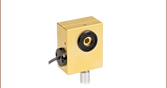
Click to Enlarge
The back of the laser head has a female HD DB26 connector that connects to the laser controller.

Modulation In
SMA Female
| Modulation In | |||
|---|---|---|---|
| Parameter | Laser Controller Setting (If Applicable) |
Value | |
| Input Impedance | 10 kΩ | ||
| Input Voltage | -10 to +10 V | ||
| Modulation Coefficient of Drive Current |
Low Sensitivity | 12 mA/V ± 5% | |
| High Sensitivity | 120 mA/V ± 5% | ||
| Input Frequencya |
Sine Wave |
Noise Reduction Off | DC to 100 kHz |
| Noise Reduction On | DC to 4 kHz | ||
| Triangle Wave |
Noise Reduction Off | DC to 40 kHz | |
| Noise Reduction On | DC to 1.5 kHz | ||
| Square Wave |
Noise Reduction Off | DC to 20 kHz | |
| Noise Reduction On | DC to 1 kHz | ||
The sensitivity level of the modulation coefficient and the status of the noise reduction filter are configured in the Laser Setup Screen (see the Controller Interface tab). Activating the noise reduction filter reduces the drive current noise by approximately 2X.
Tune In
SMA Female
| Tune In | |
|---|---|
| Parameter | Value |
| Input Impedance |
10 kΩ |
| Input Voltage | -10 to +10 V |
| Modulation Coefficient of Drive Current |
6 mA/V ± 5% |
The Tune In input is used to fine tune a DFB laser to a spectral absorption line and lock the wavelength using error signal feedback.
Sync Out
SMA Female
| Sync Out | ||
|---|---|---|
| Parameter | Value | |
| Low Level | <0.3 V | |
| High Level | 50 Ω Impedance | >2.5 V |
| 10 kΩ Impedance | >3.5 V | |
| Delay in Modulated Current with Respect to Sync Out |
Noise Reduction Off | 3 µs |
| Noise Reduction On | 30 µs | |
The TTL output signal switches from low to high when the internal modulation signal increases past zero.
Computer Control
Female USB Mini B
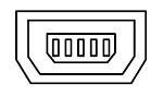
This interface allows a computer to change the controller's settings using an SCPI-compliant command set (see the Software tab) and is used to load firmware upgrades via a Windows® operating system.
Interlock
2.5 mm Mono Jack
This connector must be short-circuited to enable laser emission. A jumper pin is included with the laser system.
Ground
4 mm Banana Jack

If desired, the user may use this connector to ground the system.
Power Supply
Female 4-Pin Mini-DIN
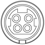
This connector provides power for
the entire laser system.
Laser Head to Controller
Female HD DB26
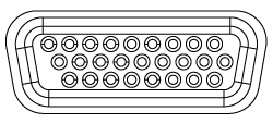
One of these connectors is located on the laser head, and another is located on the laser controller. They are used to transmit signals and power.
Drivers for Remote Control of Touchscreen Controller
The download button below links to VXIpnp instrument drivers and support documentation for operating our turnkey MIR laser system with user-written software. The controller understands the SCPI-compliant command set described in the Programming Reference tab on the software download page. The C, C++, C#, LabVIEW®, LabWindows™/CVI, and Visual Studio programming environments are supported.
Drivers
Version 1.0 (February 16, 2017)

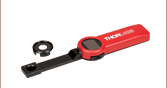
Click to Enlarge
Contents of MLQF4550 MIR Laser System Shown (North American Power Cord Shown)
Shipping List
Each turnkey MIR laser system includes:
- Factory-Calibrated Laser Head
- MLSC Touchscreen Controller
- HD DB26 Cable for Connecting Laser Head to Controller
- Three CF175 Clamping Forks for Securing Laser Head to Optical Table
- VRC6S MIR Detector Card (Not Pictured)
- USB 2.0 A to Mini B Cable for Remote Operation
- Laser Enable Key (Qty. 2)
- 2.5 mm Jumper Pin for Short Circuiting the Interlock (Ships Installed in Controller; Not Pictured)
- Power Supply and Region-Specific Power Cord
- Quick Start Guide
Click to Enlarge
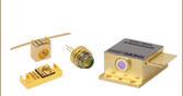
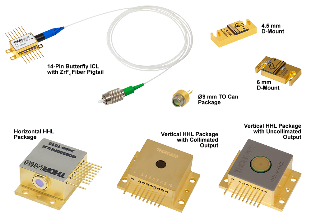
Some of Our Available Packages
Click for Details
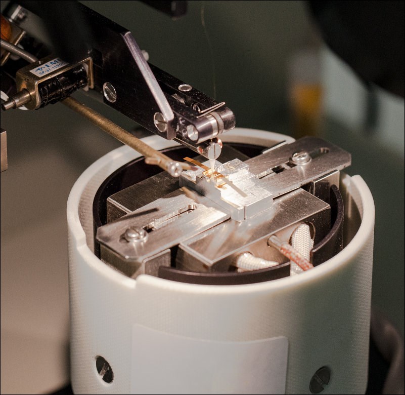
Wire Bonding a Quantum Cascade Laser on a C-Mount
Custom & OEM Quantum Cascade and Interband Cascade Lasers
At our semiconductor manufacturing facility in Jessup, Maryland, we build fully packaged mid-IR lasers and gain chips. Our engineering team performs in-house epitaxial growth, wafer fabrication, and laser packaging. We maintain chip inventory from 3 µm to 12 µm, and our vertically integrated facilities are well equipped to fulfill unique requests.
High-Power Fabry-Perot QCLs
For Fabry-Perot lasers, we can reach multi-watt output power on certain custom orders. The available power depends upon several factors, including the wavelength and the desired package.
DFB QCLs at Custom Wavelengths
For distributed feedback (DFB) lasers, we can deliver a wide range of center wavelengths with user-defined wavelength precision. Our semiconductor specialists will take your application requirements into account when discussing the options with you.
The graphs below and photos to the right illustrate some of our custom capabilities. Please visit our semiconductor manufacturing capabilities presentation to learn more.
![]()
Click to Enlarge
Available Wavelengths for Custom QCLs and ICLs
Click to Enlarge
Maximum Output Power of Custom Fabry-Perot QCLs
Click to Enlarge
Electroluminescence Spectra of Available Gain Chip Material
Laser Safety and Classification
Safe practices and proper usage of safety equipment should be taken into consideration when operating lasers. The eye is susceptible to injury, even from very low levels of laser light. Thorlabs offers a range of laser safety accessories that can be used to reduce the risk of accidents or injuries. Laser emission in the visible and near infrared spectral ranges has the greatest potential for retinal injury, as the cornea and lens are transparent to those wavelengths, and the lens can focus the laser energy onto the retina.
 |
 |
 |
 |
 |
 |
 |
 |
 |
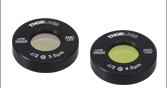
Safe Practices and Light Safety Accessories
- Laser safety eyewear must be worn whenever working with Class 3 or 4 lasers.
- Regardless of laser class, Thorlabs recommends the use of laser safety eyewear whenever working with laser beams with non-negligible powers, since metallic tools such as screwdrivers can accidentally redirect a beam.
- Laser goggles designed for specific wavelengths should be clearly available near laser setups to protect the wearer from unintentional laser reflections.
- Goggles are marked with the wavelength range over which protection is afforded and the minimum optical density within that range.
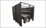
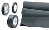
- Laser Safety Curtains and Laser Safety Fabric shield other parts of the lab from high energy lasers.
- Blackout Materials can prevent direct or reflected light from leaving the experimental setup area.
- Thorlabs' Enclosure Systems can be used to contain optical setups to isolate or minimize laser hazards.
- A fiber-pigtailed laser should always be turned off before connecting it to or disconnecting it from another fiber, especially when the laser is at power levels above 10 mW.
- All beams should be terminated at the edge of the table, and laboratory doors should be closed whenever a laser is in use.
- Do not place laser beams at eye level.
- Carry out experiments on an optical table such that all laser beams travel horizontally.
- Remove unnecessary reflective items such as reflective jewelry (e.g., rings, watches, etc.) while working near the beam path.
- Be aware that lenses and other optical devices may reflect a portion of the incident beam from the front or rear surface.
- Operate a laser at the minimum power necessary for any operation.
- If possible, reduce the output power of a laser during alignment procedures.
- Use beam shutters and filters to reduce the beam power.
- Post appropriate warning signs or labels near laser setups or rooms.
- Use a laser sign with a lightbox if operating Class 3R or 4 lasers (i.e., lasers requiring the use of a safety interlock).
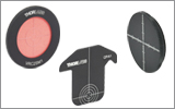
- Do not use Laser Viewing Cards in place of a proper Beam Trap.
Laser Classification
Lasers are categorized into different classes according to their ability to cause eye and other damage. The International Electrotechnical Commission (IEC) is a global organization that prepares and publishes international standards for all electrical, electronic, and related technologies. The IEC document 60825-1 outlines the safety of laser products. A description of each class of laser is given below:
| Class | Description | Warning Label |
|---|---|---|
| 1 | This class of laser is safe under all conditions of normal use, including use with optical instruments for intrabeam viewing. Lasers in this class do not emit radiation at levels that may cause injury during normal operation, and therefore the maximum permissible exposure (MPE) cannot be exceeded. Class 1 lasers can also include enclosed, high-power lasers where exposure to the radiation is not possible without opening or shutting down the laser. |  |
| 1M | Class 1M lasers are safe except when used in conjunction with optical components such as telescopes and microscopes. Lasers belonging to this class emit large-diameter or divergent beams, and the MPE cannot normally be exceeded unless focusing or imaging optics are used to narrow the beam. However, if the beam is refocused, the hazard may be increased and the class may be changed accordingly. |  |
| 2 | Class 2 lasers, which are limited to 1 mW of visible continuous-wave radiation, are safe because the blink reflex will limit the exposure in the eye to 0.25 seconds. This category only applies to visible radiation (400 - 700 nm). |  |
| 2M | Because of the blink reflex, this class of laser is classified as safe as long as the beam is not viewed through optical instruments. This laser class also applies to larger-diameter or diverging laser beams. |  |
| 3R | Class 3R lasers produce visible and invisible light that is hazardous under direct and specular-reflection viewing conditions. Eye injuries may occur if you directly view the beam, especially when using optical instruments. Lasers in this class are considered safe as long as they are handled with restricted beam viewing. The MPE can be exceeded with this class of laser; however, this presents a low risk level to injury. Visible, continuous-wave lasers in this class are limited to 5 mW of output power. |  |
| 3B | Class 3B lasers are hazardous to the eye if exposed directly. Diffuse reflections are usually not harmful, but may be when using higher-power Class 3B lasers. Safe handling of devices in this class includes wearing protective eyewear where direct viewing of the laser beam may occur. Lasers of this class must be equipped with a key switch and a safety interlock; moreover, laser safety signs should be used, such that the laser cannot be used without the safety light turning on. Laser products with power output near the upper range of Class 3B may also cause skin burns. |  |
| 4 | This class of laser may cause damage to the skin, and also to the eye, even from the viewing of diffuse reflections. These hazards may also apply to indirect or non-specular reflections of the beam, even from apparently matte surfaces. Great care must be taken when handling these lasers. They also represent a fire risk, because they may ignite combustible material. Class 4 lasers must be equipped with a key switch and a safety interlock. |  |
| All class 2 lasers (and higher) must display, in addition to the corresponding sign above, this triangular warning sign. |  |
|
| Posted Comments: | |
ebayri
(posted 2018-12-18 02:21:48.093) Dear Sir/Madam,
We are looking for single frequency (narrow band) QCL laser between 4.3-4.4um wavelength? Could you provide such product and what is the maximum power level for such unit? Can we specify wavelength during purchase order?
Best regards, YLohia
(posted 2018-12-21 10:06:29.0) Hello, thank you for contacting Thorlabs. Custom items can be requested by emailing techsupport@thorlabs.com. It is possible to specify wavelengths before being formally quoted and the minimum output power required for your application should also be specified along with it. We can then check the feasibility of offering a custom solution suited for your needs. |

 Zoom
Zoom| Webpage Features | |
|---|---|
 |
Clicking this icon allows you to download our standard support documentation. |
|
Choose Item |
Clicking the words "Choose Item" opens a drop-down list containing all of the in-stock lasers around the desired center wavelength. The red icon next to the serial number then allows you to download that device's data sheet. |
- Fabry-Perot Lasers with 4.00 µm, 4.55 µm, or 10.5 µm CWL
- Minimum Output Power:
- MLQF4000 and MLQF4550: 250 mW
- MLQF10500: 200 mW
- Center Wavelengths from 3 to 12 µm Available by Contacting Tech Support
- Includes Factory-Calibrated Laser Head, Touchscreen Controller, and All Other Items in Shipping List Tab
MIR Fabry-Perot lasers that emit at a center wavelength of 4.00 µm, 4.55 µm, or 10.5 µm are available. The minimum optical output power is 250 mW for the MLQF4000 and MLQF4550 lasers and 200 mW for the MLQF10500 laser. The lasers exhibit broadband emission, in a range spanning roughly 50 cm-1 for the MLQF4000 and MLQF4550 lasers and roughly 30 cm-1 for the MLQF10500 laser. Each laser's specified output power is the sum over the full spectral bandwidth. Because these lasers have broadband emission, they are well suited for medical imaging, illumination, and microscopy applications. The optical output is vertically polarized.
Before shipment, the spectrum, output power, and beam profile are measured for each serial-numbered device by an automated test station. These measurements are available by clicking "Choose Item" below and are also included on a data sheet with the laser.
Since the EEPROM in the laser head contains all the values required for calibrated operation, it is possible to purchase additional laser heads and operate them with the same controller. Thorlabs' semiconductor foundry regularly fabricates laser chips that are suitable for these turnkey systems. To inquire about wavelength and output power availability, please contact Tech Support.
 Quantum Cascade Lasers<br>")
 Zoom
Zoom| Webpage Features | |
|---|---|
|
Clicking this icon allows you to download our standard support documentation. |
|
Choose Item |
Clicking the words "Choose Item" opens a drop-down list containing all of the in-stock lasers around the desired center wavelength. The red icon next to the serial number then allows you to download that device's data sheet. |
- DFB Lasers with Single-Frequency Output
- CWLs from 4 to 5 µm and from 9 to 10 µm Available from Stock
- CWL Tunable Over a 1 to 5 cm-1 Range
- 5 mW Minimum Output Power
- MLQD4500: 40 mW Typical Output Power
- MLQD9500: 30 mW Typical Output Power
- Includes Factory-Calibrated Laser Head, Touchscreen Controller, and All Other Items in Shipping List Tab
- Center Wavelengths from 4 to 11 µm Available by Contacting Tech Support
Distributed-Feedback (DFB) Quantum Cascade Lasers emit at a well-defined center wavelength within 4 to 5 µm or 9 to 10 µm and provide single spatial mode operation. By tuning the input current and internal temperature, the output frequency can be tuned over a narrow range between 1 cm-1 and 5 cm-1. They are ideal for chemical sensing, optical communications, and other applications.
Before shipment, the spectrum, output power, and beam profile are measured for each serial-numbered device by an automated test station. These measurements are available by clicking "Choose Item" below and are also included on a data sheet with the laser. Please note that the narrow tuning range for each serial-numbered DFB laser is specified on the support documentation; these lasers are not tunable over the entire 4 to 5 µm or 9 to 10 µm range.
Each laser head is shipped with an onboard EEPROM that contains the factory-measured center wavelength, L-I-V characteristics, and wavelength / wavenumber tuning characteristics. Since the EEPROM in the laser head contains all the values required for calibrated operation, it is possible to purchase additional laser heads and operate them with the same controller. Thorlabs' semiconductor foundry regularly fabricates laser chips that are suitable for these turnkey systems. To inquire about wavelength and output power availability, please contact Tech Support.