 Products Home
Polymer Engineered Diffusers®
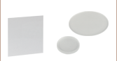
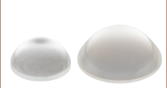
- Square, Circular, and Line Scatter Shapes
- Design Wavelength: 400 nm - 700 nm
- Transmission: 90%
- Unmounted and Mounted Ø1" Diffusers Available
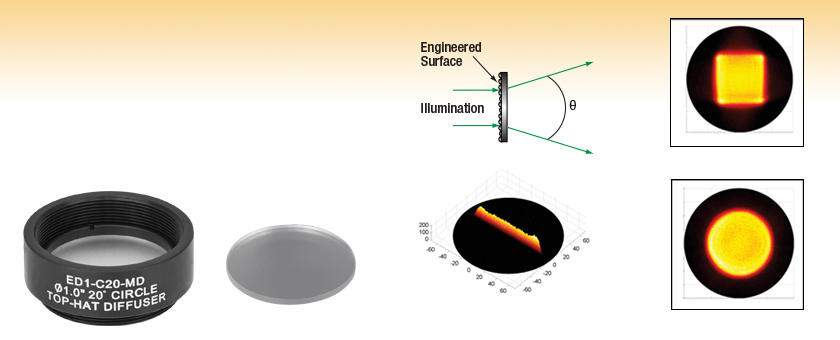
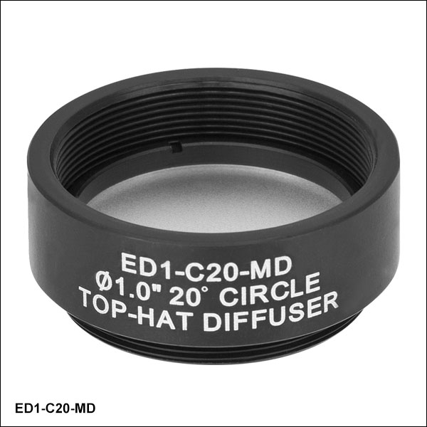
ED1-C20-MD
20° Circle Pattern, Mounted
ED1-C20
20° Circle Pattern, Unmounted
Line Pattern
Square Pattern
Circle Pattern


Please Wait
| Diffuser Selection Guide | |||
|---|---|---|---|
| Ground Glass Diffusers | |||
| Type | Material | Mounting, Coating | Operating Wavelength |
| Standard Diffusers | N-BK7 Substrate | Unmounted, Uncoated | 350 nm - 2.0 μm |
| Unmounted, AR Coated | 350 nm - 700 nm 650 nm - 1050 nm |
||
| Mounted, Uncoated | 350 nm - 2.0 µm | ||
| UVFS Substrate | Unmounted, Uncoated | 185 nm - 2.0 µm | |
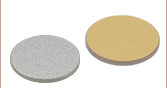
| Diffuse Reflectors | N-BK7 Substrate | Unmounted, UV-Enhanced Aluminum Coated |
250 nm - 450 nm |
| Unmounted, Protected Silver Coated | 450 nm - 20 µm | ||
| Unmounted, Protected Gold Coated | 800 nm - 20 µm | ||
| Alignment Disks | |||
| Engineered Diffusers | |||
| Type | Material | Mounting, Coating | Operating Wavelength |
| Glass Diffusers | UVFS Substrate | Unmounted and Mounted, Uncoated | 400 nm - 700 nm |
| Polymer Diffusers | ZEONOR Substrate | Unmounted and Mounted, Uncoated | 400 nm - 700 nm |
| Diffuser Kits | |||
Features
- Ø1" Diffusers
- Input Illumination Homogenized to Circle, Square, or Line Pattern Profiles
- ZEONOR Polymer Substrate
- Design Wavelength Range from 400 - 700 nm
- 90% Transmission Efficiency from 380 nm - 1100 nm
- Available Unmounted or Mounted
- Ideal for Low-Power Applications
Thorlabs offers Polymer Engineered Diffusers®*, which provide non-Gaussian intensity distributions in square, circular, and line distribution patterns (see the Graphs tab). Over their design wavelength, these diffusers have a square or circular distribution pattern with a 20° or 50° divergence angle, while the line distribution has a 0.4° x 100° divergence; typical diffusers do not offer this advanced level of light control.
These cost-effective engineered diffusers are made from injection molded ZEONOR polymer and have 90% transmission efficiency from 380 nm - 1100 nm. They are ideal for low-power applications and are designed for use with Ø0.5 mm or larger beams; smaller beams should be expanded prior to the diffuser. For high-power applications or applications requiring UV transmission, Thorlabs offers UV Fused Silica Engineered Diffusers.
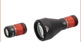
Our polymer engineered diffusers are available unmounted or mounted. The mounted Ø1" diffusers come in an engraved SM1-threaded (1.035"-40) mount, as shown at the top of the webpage. The mount provides quick identification and helps protect the diffusers from fingerprints and other contamination. SM1 threading is particularly useful when building
Please see the Technology tab for more information on the technology and fabrication of our Engineered Diffusers.
*Engineered Diffusers® is a registered trademark of VIAVI Solutions, Inc.
| Common Specifications | |
|---|---|
| Material | Injection Molded ZEONOR |
| Design Wavelengtha | 400 - 700 nm (Achromatic) |
| Transmission Spectruma | 380 - 1100 nm |
| Diffuser Diameter | Ø25.4 mm (Ø1") |
| Diffuser Thickness | 1.5 mm (0.06") |
| Incident Beam Size | ≥0.5 mm |
| Index of Refraction | 1.53 |
| Item # | Pattern | Divergencea | Transmission Efficiency | ||
|---|---|---|---|---|---|
| Flat Intensity Regionb | 50% of Max Intensityc | 10% of Max Intensityd | |||
| ED1-C20(-MD) | Circle | 20° | 27° | 36° | 90% |
| ED1-C50(-MD) | Circle | 50° | 60° | 70° | 90% |
| ED1-S20(-MD) | Square | 20° | 27° | 36° | 90% |
| ED1-S50(-MD) | Square | 50° | 60° | 70° | 90% |
| ED1-L4100(-MD) | Line | 100° | 105° | 115° | 90% |
Introduction
These Polymer Engineered Diffusers® are designed to create non-Gaussian intensity distributions in circular or square beam profiles that diverge from the plane of incidence. Figures 4.1, 4.3, 4.5, 4.7, and 4.9 are the theoretical approximations of the intensity through the center of the diverging beam profile when illuminating the engineered diffusers with a 633 nm collimated beam. Figures 4.2, 4.4, 4.6, and 4.8 contain data compiled from independent tests with laser wavelengths of 488 nm, 637 nm, 785 nm, and 1064 nm to demonstrate the change in output profile with wavelength. The highlighted region of each graph denotes the divergence angle of the engineered diffuser. At the bottom of this tab is a description of the laboratory setup and procedure used to collect these data and the results.
Circular Pattern Diffusers Transmitted Intensity Plots
|
|
 Click to Enlarge Click to EnlargeFigure 4.2 Experimental Data for ED1-C20 Raw Data |
 Click to Enlarge Click to EnlargeFigure 4.3 Theoretical Data for ED1-C50 |
 Click to Enlarge Click to EnlargeFigure 4.4 Experimental Data for ED1-C50 Raw Data |
 Click to Enlarge
Square Pattern Diffusers Transmitted Intensity Plots
 Click to Enlarge Click to EnlargeFigure 4.5 Theoretical Data for ED1-S20 |
 Click to Enlarge Click to EnlargeFigure 4.6 Experimental Data for ED1-S20 Raw Data |
 Click to Enlarge Click to EnlargeFigure 4.7 Theoretical Data for ED1-S50 |
 Click to Enlarge Click to EnlargeFigure 4.8 Experimental Data for ED1-S50 Raw Data |
Line Pattern Diffuser Transmitted Intensity Plot
Click to Enlarge
Figure 4.9 Theoretical Data for ED1-L4100
Click to Enlarge
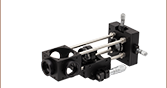
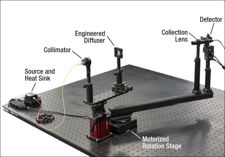
Figure 4.10 Note: A previous-generation NR360Sa Rotation Mount was used in the above experimental set-up. High Performance Black Masking Tape was used to cover metal which might reflect laser light. A MFF101 Motorized Flipper with an empty LMR05 is not being used.
| Light Preparation | ||||
|---|---|---|---|---|
| Wavelength (nm) | 488 | 637 | 785 | 1064 |
| Source | LP488-SF20 | LP637-SF70 | LP785-SF100 | DBR1064S |
| Heat Sink | LDM9LP | LM14S2 | ||
| Collimator | TC06FC-543 | TC06FC-633 | TC06APC-780 | TC06APC-1064 |
Procedure
Four wavelengths of light were chosen for study: 488 nm, 637 nm, 785 nm, and 1064 nm. These were prepared using the equipment in Figure 4.10 (a full list of all parts used can be found in the figure caption). The optical path was approximately 35 cm above the surface of the breadboard; it began when fiber-coupled light sources were collimated with triplet collimators, using a design wavelength as close to the source wavelength as possible. In free space, the beams were incident upon one of the Polymer Engineered Diffusers. The exiting divergent profile was isolated and focused by an LA1304 plano-convex lens attached to an SM05L20 lens tube. The signal was sampled every 0.5° by a SM05PD1A photodiode. This assembly was mounted on the end of an XT34-500 rail. The opposite end of the rail was mounted to a previous-generation NR360Sa rotation stage centered with the engineered diffuser under test in order to sweep the detector and lens assembly through the center of the profile, as illustrated in Figure 4.11, and plot normalized intensity versus output angle. The distance between the diffuser and the detector was approximately 43 cm. The output angle was defined with respect to the original optical axis when the diffuser was not within the path. In order to control for ambient light, a 1 kHz sine wave was used to modulate the drive current applied to the laser diode and the signal was acquired with a lock-in amplifier. A LabVIEW program was written to control the setup and acquire the data.
Experimental Limitations
Only one of each Item # was testedb. Stability may have been compromised by the experiment being performed on a PBG11113c breadboard without any isolation. Only the middle of each diffuse shape was measured, so variances in other areas of the shape are possible, including the corners of the square profiles.
Results
It was found that there was little variance in diffuse beam profile with respect to wavelength across the middle of each beam profile. Figures 4.1, 4.3, 4.5, 4.7, and 4.9 include the theoretical estimations of intensity across the width of the resulting beam profile. Figures 4.2, 4.4, 4.6, and 4.8 contain data compiled from independent tests with various laser wavelengths to verify the theoretical models.
| Item # | Theoretical | Experimental | Raw Data | |
|---|---|---|---|---|
| Circular Patterns | ED1-C20 | Click Here | ||
| ED1-C50 | Click Here | |||
| Square Patterns | ED1-S20 | |
|
Click Here |
| ED1-S50 | |
|
Click Here | |
| Line Pattern | ED1-L4100 | |
Not Available | Not Available |
Click to Enlarge
Figure 4.11 Detector Path Through Diffuse Profiles
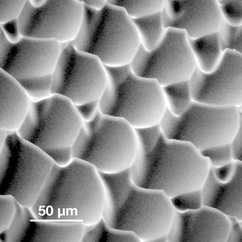
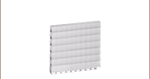
Click to Enlarge
SEM Picture of Engineered Diffuser for Display Brightness Enhancement
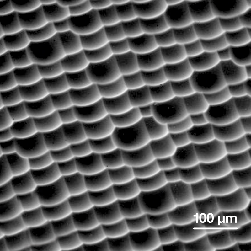
Click to Enlarge
SEM Picture of Engineered Diffuser for Projection Screens
Engineered Diffuser® Technology
Engineered Diffusers provide advanced beam shaping that leads to significant performance enhancements for applications as diverse as lithographic systems, outdoor lighting, displays, backlighting, display brightness enhancement, and projection screens.
Homogeneous diffusers made of, for example, ground glass, opal glass, or holographic elements, consist of repeating, uniform surface patterns across the entire clear aperture that provide only limited control over the shape and intensity profile of the illuminated area, causing the incident light to be used inefficiently. In addition, holographic diffusers are usually limited to monochromatic applications using coherent light. On the other hand, Engineered Diffusers consist of differing, individually manipulated microlens units that provide broadband compatibility and excellent control over the light distribution and beam profile.
Each microlens unit that forms the diffuser is individually specified with respect to its surface profile and location in the array. At the same time, to ensure that the diffuser is stable against variations in the input beam's intensity profile and usable in the visible and IR, the distribution of microlenses is randomized according to probability distribution functions chosen to implement the desired beam shaping functions. The microlens distribution also removes zero-order bright spots and diffraction artifacts from the output. In this manner, Engineered Diffusers retain the best properties of both random and deterministic diffusers.
Click to Enlarge
Diagram of Mastering Process
Fabrication
The master microlens array is produced by a laser writing system developed by VIAVI Solutions, Inc. This system exposes a thick layer of photoresist point-by-point in a raster scan mode, as shown to the left. By modulating the intensity of the laser beam as it is scanned, the degree to which the photoresist is exposed can be varied. A deeply textured, engineered surface is the result, as shown above in the two SEM images of the surface topography.
Comparison to Other Diffuser Technologies
Other common diffuser types include prismatic glass integrating bars, ground glass, opal glass, holographic diffusers, and diffractive diffusers. Prismatic glass integrating bars, though sometimes used in high-end systems, are expensive and occupy a great deal of precious space. Ground and opal glass scatter light equally in all directions but with a low degree of control. In addition, efficiency is generally poor with these simple diffusers. Holographic diffusers are an improvement on these technologies and enable limited production of light distribution patterns, but only offer Gaussian-like intensity profiles and circular or elliptical patterns. In terms of general beam shaping capability, diffractive elements can shape an input beam arbitrarily. However, they are confined to narrow diffusion angles, highly sensitive to wavelength, and cannot eliminate zero-order bright spots collinear with the incident beam. In contrast, Engineered Diffusers provide high transmission efficiencies and the ability to control the divergence angle, spatial distribution, and intensity profile of the diffused light.
For more information on Engineered Diffuser technology and performance, please read our Optical Diffusers Catalog Presentation.
| Posted Comments: | |
Junwon Lee
(posted 2025-06-25 17:02:30.697) I would like to know about the threshold of Polymer Engineered Diffusers. In the Overview, it is briefly mentioned as low power. EGies
(posted 2025-07-07 11:42:55.0) Thank you for contacting Thorlabs. We do not have an official damage threshold rating for these diffusers I have reached out to you directly to discuss your specific setup conditions. user
(posted 2025-05-21 08:34:51.903) What does the "relative intensity" depicted in the graphs represent? Is there a formula that describes it? Does relative intensity have a measurement unit? simon labouesse
(posted 2025-04-16 10:17:09.917) I am planning to generate a fully developed speckle by imaging a diffuser on the sample plane of a microscope. The setup includes a 200mm tube length and a 100x NA 1.49 objective at a 488nm wavelength. My goal is to minimize light losses. Could you advise whether a 50° or 20° square diffuser would be more suitable for this purpose? Additionally, should I use a 4f relay system between the tube length and the diffuser? If so, what focal lengths would you recommend for the lenses in this setup? Thank you for your assistance. EGies
(posted 2025-05-09 11:36:03.0) Thank you for contacting Thorlabs. I have reached out to you directly regarding this. 미숙 정
(posted 2025-02-06 21:37:23.877) I would like to inquire about the output characteristics of this engineered diffuser when an oblique beam (approximately 10° incident angle) is applied. The incident beam has a telecentric focusing profile with a numerical aperture (NA) of approximately 0.17 at the diffuser and a beam diameter of around 10 mm. Under these conditions, would it be possible to achieve a uniform beam distribution within a ±20° angular range? EGies
(posted 2025-02-07 01:37:21.0) Thank you for contacting Thorlabs. The engineered diffusers like ED1-S20 are designed to be used with a collimated beam. When used with a divergent beam, you will see some distortion of the output, typically some blurring at the edges of the pattern in particular. The output also becomes wider with increasing divergence angle of the input. I have reached out to you directly regarding your specific application. Faith Stoll
(posted 2025-01-22 17:19:10.99) Hello. I have a 5 W 450 nm laser with an adjustable focus lens to ensure the beam is wider than 0.5 mm for this lens application. Would the ED1-S50-MD work to irradiate a 10 cm by 10 cm area? tdevkota
(posted 2025-01-27 12:15:13.0) Thank you for contacting Thorlabs. The ED1-S50-MD has a divergence angle of 50 degrees, meaning that as you move away from the diffuser, the illumination area will expand as well. I have reached out to you directly to discuss your application further. Tigrane Cantat-Moltrecht
(posted 2025-01-09 16:36:33.423) Hello, I would like to know how the performance degrades depending on the incident beam quality, could you shed some light on that ?
Right now when projecting on a flat plane at a distance of 10-20 cm at normal incidence, I get significant inhomogeneity (+/- 30% from sides to center). This is with a laser beam out of a .25 NA 400µm core MM fiber.
Thanks for your help. blarowe
(posted 2025-01-10 09:13:43.0) Thank you for contacting Thorlabs. These diffusers tend not to be particularly sensitive to the quality of the input beam, and can work as expected regardless of the input beam's shape and profile. Haeni Lee
(posted 2024-07-25 04:24:37.62) Hi. We are using a pulse laser with a maximum pulse of 350 mJ at 1,064 nm. The beam diameter is less than 1 cm.
We are looking for an appropriate optical diffuser to expand this beam to 10 x 10 cm², and the ED1-C50 seems suitable.
Could you please inform us of the power tolerance for this diffuser?
Additionally, although the design wavelength is 400 - 700 nm, the divergence angle appears to be maintained at 1,064 nm according to the graph.
Could you confirm this? We also welcome suggestions for other suitable diffusers. jdelia
(posted 2024-07-30 09:37:06.0) Thank you for contacting Thorlabs. I have reached out to you directly to clarify your beam parameters and discuss whether it may be suitable for these optics. Regarding the wavelength range, the ZEONOR substrate has a broad transmission spectrum, but the Polymer Engineered Diffusers® are only guaranteed to meet the divergence angle specifications within the design wavelength range. user
(posted 2024-05-30 23:25:07.377) Can you comment on the optimal distance between the light source and the diffuser?
What is the best way to clean the diffuser? cdolbashian
(posted 2024-06-18 12:38:39.0) Thank you for reaching out to us. These diffusers are nominally designed to work with collimated inputs, which will achieve the advertised intensity distribution. Ideally you want to ensure, if you have a diverging light source that it nominally is not missing the diffuser. Other than that, if you have a high intensity light source, you want to expand the beam, or move farther away such that you will not damage the surface. I have contacted you directly to discuss your application and share some additional resources regarding expected performance and best practices when using these components. martin carbonnaux
(posted 2024-01-17 10:12:29.91) Hi, we are using the ED1-S20 with a colimated gaussian input and we would like to know if it would be possible to put a colimated top-hat input instead (using the NDY10B for instance) for a better power distribution. Thanks! jdelia
(posted 2024-01-23 11:50:03.0) Thank you for contacting Thorlabs. The input beam profile should not matter in this case. I have reached out to you directly to discuss your application further. martin carbonnaux
(posted 2024-01-17 10:11:53.54) Hi, we are using the ED1-S20 with a colimated gaussian input and we would like to know if it would be possible to put a colimated top-hat input instead (using the NDY10B for instance) for a better power distribution. Thanks! zhengyu LI
(posted 2023-11-07 11:02:26.86) hello thorlabs,i use a lens to collimate the beam after ED1-C202 diffuser, but i find the beam spread strongly after the beam waist,please explain this phenomenon and is there any solution,thankyou so much LI Zhengyu
(posted 2023-10-25 16:31:08.973) hello thorlabs,i would like to know if it is possible to collimate the beam after the diffuser with a focusing lens? cdolbashian
(posted 2023-11-08 12:46:56.0) Thank you for reaching out to us with this inquiry. I have contacted you to directly to discuss your application and the feasibility of what you are trying to achieve. Angel Fernandez Alvarez
(posted 2023-10-06 06:52:05.58) Dear Thorlabs Team,
I need a customized engineering diffuser:
- 2 inch diameter
- Circle or square pattern
- 50 degrees of preference---but can also be 20 degrees
- Mounted
Could you do it? If so, how long does it take you to do it?
Thank you in advance for your help.
Yours sincerely,
Ángel. Gyeongwon Lee
(posted 2023-09-04 14:41:22.477) I'd like to get transmission curve for ED1-S20-MD and ED1-C20-MD, simulataneously.
And could you get the tip to utilize the diffuser? cdolbashian
(posted 2023-10-26 08:32:11.0) Thank you for reaching out to us with this inquiry. I have contacted you directly with the transmission data for the diffuser substrate: Zeonor. Additionally, I have shared some usage tips, and guidelines for implementing these components. Oliver Li
(posted 2023-06-21 21:03:15.783) Hello Thorlabs, would you like to give me some information on the size of the microcell of the diffuser? Thank you! cdolbashian
(posted 2023-06-23 01:57:37.0) Thank you for reaching out to us with this inquiry. I have contacted you to discuss the specifics of these diffusers. Angel Chung
(posted 2023-06-09 15:08:36.277) I would like to know if this kind of diffuser made by the composition of microlens could solve the speckle issue caused by white-glass diffuser and provide uniform beam profile. Thanks! cdolbashian
(posted 2023-06-20 02:33:05.0) Thank you for reaching out to us Angel! What you are describing sounds very similar to the design of our Fly's Eye Beam expander. I have contacted you directly to discuss your issue. Matan Yosefi
(posted 2023-05-30 23:24:00.157) Hello, do you have diffusers for WL of 1064 to 1550 nm for top hat intensity? cdolbashian
(posted 2023-06-01 04:07:41.0) Thank you for reaching out to us Matan. The diffusers we present above should work for these wavelengths. Lukas Klein
(posted 2022-11-25 09:04:28.49) Hello,
I would like to ask about the transmission spectrum of the engineered diffusers. In our experiment, we are using the diffuser up to 2300nm, which we're aware is significantly above the designed limit. We are, however, curious because while the transmission spectrum is overall satisfying for our application, we see a significant intensity drop around 1600nm. Is this related to the structure on the surface? Based on the photos, the dents and photoresist thickness are still significantly bigger (around 50 um), so diffraction shouldn't be a major concern. Thank you in advance for your answer. Ayano Nishimia
(posted 2022-11-23 16:34:45.853) Hello Thorlabs, our team wants to know the working distance of the diffuser so that we can put the diffuser as close as possible to the diffuser. Thank you! ksosnowski
(posted 2022-12-02 12:13:16.0) Thanks for reaching out to Thorlabs. We do not specify a working distance for the engineered diffusers. Though they are similar in some ways to a microlens array, they are intended to be used with a collimated input beam, and produce a divergent output with specific beam profiles depending on the style of diffuser used. user
(posted 2022-10-03 09:34:49.047) Dear Thorlabs, Is there any data on transmission up to 2.5um? Thank You cdolbashian
(posted 2022-10-24 09:23:08.0) Thank you for reaching out to us with this inquiry. Unfortunately we do not have data up to 2.5um. I have sent you the data we do have which extends to ~2.4um. Philip Cheney
(posted 2022-08-21 10:29:40.107) What is the laser-induced damage threshold for the engineered diffusers?
The spec mentions 90% transmission. Is the other 10% reflected or absorbed?
Thanks! cdolbashian
(posted 2022-09-07 02:46:50.0) Thank you for reaching out to us with your inquiry. The glass used here is uncoated ZEONOR glass. The 92% transmission is likely ~4% reflection + 4% absorption though these numbers are approximate. We do not have a damage threshold rating for these diffusers. In the past, we have used these with 20 W/cm^2 without any issues. We have also found that deformation/distortion from heat occurs at ~ 99°C. That being said, these were designed for low-power applications (generally around room temperature). For best performance, your input should be collimated to the maximum possible beam diameter for a lower power density. chris e
(posted 2022-07-21 10:57:33.46) Hi, do you have or can you acquire surface roughness data for the ED1-S20? Thanks. cdolbashian
(posted 2022-07-26 03:37:34.0) Thank you for reaching out to us with this inquiry. Based on communications with the vendor, we have been told that the surface features are on the order of 90-100um. Zihao Pang
(posted 2022-06-16 07:21:33.34) Dear Sir or Madam,
We are so interested in your product Engineered Diffusers. We are wondering if there is any chance that you can customize the diffuse pattern for us. For example, can we get an Engineered Diffuser that can provide a diffuse Gaussian intensity distribution in 20 degree divergence angle?
Best,
Zihao cdolbashian
(posted 2022-06-17 04:56:40.0) Thank you for reaching out to us Zihao with this custom request! I have contacted you directly to discuss the best way for us to create such a diffuser. user
(posted 2022-06-09 08:10:46.39) The Square Pattern Diffusers Transmitted Intensity Plot for ED1-S20 does not have a relative intensity axis that runs from 0 to 1. Instead it runs from 0 to 8 and is inconsistent with the other plots cdolbashian
(posted 2022-06-09 02:16:31.0) Thank you for your feedback. As these were made in collaboration with an external vendor, RPC photonics, we received the theoretical data from them regarding the performance. In contrast, the colored experimental data was taken by us to verify the the theoretical performance. Taoran Li
(posted 2021-12-23 16:45:35.91) RPC Photonics网站上已有各种发散角的工程散射体,为什么Thorlabs上没有,不是说和RPC Photonics共同推出的么??? YLohia
(posted 2021-12-23 10:24:11.0) Hello, an applications engineer from our team in China (techsupport-cn@thorlabs.com) will discuss this with you. Dirk Schwarzer
(posted 2021-09-22 07:25:08.373) What isthe damage threshold for the ED1-C50 - Ø1" 50° Circle Pattern Diffuser YLohia
(posted 2021-09-22 10:20:02.0) We do not have a damage threshold rating for these diffusers. In the past, we have used these with 20 W/cm^2 without any issues. We have also found that deformation/distortion from heat occurs at ~ 99°C. That being said, these were designed for low-power applications (generally around room temperature). For best performance, your input should be collimated to the maximum possible beam diameter for a lower power density. Bianka Csanaková
(posted 2021-09-13 08:58:23.06) Hello
I would like to ask for the transmission curves of the circular flat top engineered diffuser in the near-IR (up to 2 um).
Thank you. YLohia
(posted 2021-09-14 03:43:56.0) Hello, thank you for contacting Thorlabs. Transmission curves for these can be requested by emailing techsupport@thorlabs.com. I have reached out to you directly with some data. Martin Garmund
(posted 2021-06-07 08:27:55.13) Hello,
Is it possible to decrease the 100deg expansion angle somewhat (the ED1-L4100) if instead of hitting with a collimated beam, you have a converging/focused beam hitting the diffuser? Or is there other ways to alter the ratio of the two axis eg by using a cylindrical lens in on of the axis after the diffuser to "compress" the width to the hight?
Thank you for your time,
Kind regards
Martin Garmund cdolbashian
(posted 2021-07-12 09:40:09.0) Thank you for reaching out to us Martin! These diffusers were made in collaboration with RPC photonics, as it says on our product page. They actually have an excellent document which is extremely helpful when determining the performance of this device under various conditions, including while using a non-collimated source:
https://www.rpcphotonics.com/how-to-use-engineered-diffusers/
I have reached out to you directly to discuss this further. Kuang-Po Chang
(posted 2021-06-07 12:22:58.24) Hi,
Our application requires a beam spot at focal plane 2mm by 100 microns line shape. Is it possible to focus your line diffused pattern down to this size? If possible please advice an optical geometry to have it done. Ideally the components involved please also show me the Thorlabs part number, thanks!
Our application is polarization sensitive hence hopefully your engineered diffuser element won't change the polarization of the laser beam as an ordinary diffuser did.
We use two lasers at 532 nm and 640 nm. The beam size are the same at 0.7 mm and the laser power are 500 mW. They are 1000:1 linearly polarized.
Thanks for your help in advance!
Regards,
Kuang-Po
Kuang-Po CHANG, PhD
Personal Genomics, Inc. TAIWAN
kpchang@personalgx.com
Tel: +886- 3-5910323 # 220
http://www.personalgx.com/ cdolbashian
(posted 2021-06-14 05:09:38.0) In general the polarization state after the diffuser will change based on the position of the beam within each individual engineered area and the incident polarization state. I have reached out to you directly to discuss your application-specific inquiries. 钰磊 常
(posted 2021-05-21 21:24:32.513) 本产品是否附带卡环,如果不,请问配套卡环的具体型号是什么?或是货号。谢谢 YLohia
(posted 2021-05-21 10:54:39.0) Hello, an applications engineer from our team in China (techsupport-cn@thorlabs.com) will discuss this directly with you. Alon Zaharony
(posted 2021-01-31 09:35:14.47) Hi,
Regarding the ED1-L4100-MD.
1) I would like to use it in order to create a collimated line (for the first dimension. the second one will suffer from the 0.4 degrees of diversion).
Which lens would you recommend to use for this purpose? Is there any better solution for this goal?
2) What is the intensity profile of the projected line across the short dimension?
Thanks,
Alon YLohia
(posted 2021-02-16 02:25:26.0) Hello, thank you for contacting Thorlabs. 1) You could also use a plano-cylindrical lens to collimate only one axis of the laser beam profile: https://www.thorlabs.com/Navigation.cfm?Guide_ID=14. 2) I have reached out to you directly with the intensity profile of the short dimension for the ED1-L4100. Mathieu GUILHEM
(posted 2020-11-25 08:21:38.537) Hello, do you know the diffraction efficiency ? Is there is significant zero order after the diffuser ? YLohia
(posted 2020-12-09 02:21:28.0) Hello, thank you for contacting Thorlabs. The ED1-S20-MD is not a diffractive element so there is no zero order hot spot and the component works over a broadband spectrum. The total transmission is about 90%. user
(posted 2020-11-13 13:42:24.95) Do you have line diffuser with a smaller size, like ~Ø5mm? YLohia
(posted 2020-11-13 02:00:42.0) Thank you for contacting Thorlabs. Custom versions of these optics can be requested by clicking on the "Request Quote" button above. We will discuss the possibility of offering this customization directly. Josep Serres
(posted 2020-09-10 08:02:22.707) What is the damage threshold? YLohia
(posted 2020-09-10 12:07:30.0) We do not have a damage threshold rating for these diffusers. In the past, we have used these with 20 W/cm^2 without any issues. We have also found that deformation/distortion from heat occurs at ~ 99°C. That being said, these were designed for low-power applications (generally around room temperature). For best performance, your input should be collimated to the maximum possible beam diameter for a lower power density. Andre Kleinwächter
(posted 2020-09-07 07:06:15.317) Sehr geehrte Damen und Herren,
können Sie eine Auskunft geben über die maximale Laserleistung (bzw. Laserenergie) geben, mit der diese Aufweitungsoptik betrieben werden kann?
Mit freundlichem Gruß!
Andre Kleinwächter YLohia
(posted 2020-09-08 09:15:29.0) Hello Andre, thank you for contacting Thorlabs. An applications engineer from our team in Germany will reach out to you directly. user
(posted 2020-09-05 17:38:07.013) I have 2 questions regarding the line diffuser. What is the width (short dimension) of the projected line? 2) what is the intensity profile if the projected line across the short dimension? Thank you. YLohia
(posted 2020-10-15 09:16:00.0) Thank you for contacting Thorlabs. The short dimension of the projected line from the ED1-L4100 has a FWHM of 0.4 deg. I have reached out to you directly with the intensity profile. YUPIN LAN
(posted 2020-04-07 02:08:42.0) How much laser power can these elements withstand? YLohia
(posted 2020-04-07 09:20:21.0) We do not have a damage threshold rating for these diffusers. In the past, we have used these with 20 W/cm^2 without any issues. We have also found that deformation/distortion from heat occurs at ~ 99°C. That being said, these were designed for low-power applications (generally around room temperature). For best performance, your input should be collimated to the maximum possible beam diameter for a lower power density. Chee Lap Chow
(posted 2020-03-18 05:31:54.547) Dear Sir/Madam,
Can I check with you on the Damage Threshold for the Engineered Diffuser? I wish to use it for my laser system with the following specifications (wavelength: 860nm, Energy: 1mJ, Pulse width: 4-6ns, FC output).
Please advise.
Thanks YLohia
(posted 2020-03-18 08:32:09.0) We do not have a damage threshold rating for these diffusers. In the past, we have used these with 20 W/cm^2 without any issues. We have also found that deformation/distortion from heat occurs at ~ 99°C. That being said, these were designed for low-power applications (generally around room temperature). For best performance, your fiber output should be collimated to the maximum possible beam diameter for a lower power density. Moongyu Han
(posted 2020-02-19 06:05:43.357) What is the Damage threshold & Temperature range of the engineered diffuser??
Thank you llamb
(posted 2020-02-20 04:02:16.0) Thank you for contacting Thorlabs. We do not have a damage threshold rating for these diffusers. In the past, we have used these with 20 W/cm^2 without any issues. We have also found that deformation/distortion from heat occurs at ~ 99°C. That being said, these were designed for low-power applications (generally around room temperature) so it would be best if you are able to use the maximum possible beam diameter for a lower power density. Benjamin Nagler
(posted 2020-02-03 02:55:03.113) Dear Thorlabs, I would like to combine several engineered diffusers in series. How does the total scattering angle relate to the individual scattering angles? nbayconich
(posted 2020-02-13 09:07:21.0) Thank you for contacting Thorlabs. There is not a simple function to relate the individual scattering angles to the scatter angle design, however the intensity distribution can be simulated using the BSDF(bidirectional scattering distribution function) zemax files which we can provide. I will reach out to you directly with more information. user
(posted 2020-01-08 10:16:08.687) Hello Thorlabs team,
you state that these diffusers are ideal for low power applications. What is the damage threshold for them? Furtehr, can the beam be collimated after passing the diffuser? YLohia
(posted 2020-01-08 02:15:28.0) Hello, we do not have a damage threshold rating for these diffusers. In the past, we have used these with 20 W/cm^2 without any issues. After your collimated source passes through the engineered diffuser, your source can no longer be considered a single point source. Therefore, it is not possible to perfectly collimate the light after the diffuser. A lens can be used after the diffuser to help reduce the amount divergence created by the diffuser, however, the beam size will still diverge as a function of distance. Using a high NA aspheric condensor lens is recommended for use, if possible. Sakees Chidambaram
(posted 2019-10-21 13:40:23.337) Hi!
Would you suggest 'Engineered Diffusers' to convert a white light source of near-Gaussian profile to flat-top profile? If not, is there any particular model you would suggest for the same? (we could use Apodizing reflective ND filters, but the output profile to be converted may not be an ideal Gaussian profile. Or will this do the job regardless of the above fact?) thanks! YLohia
(posted 2019-10-21 12:15:22.0) Hello, thank you for contacting Thorlabs. The engineered diffusers can be used with broadband sources such as LEDs. Please note that it is very important to have a well collimated input beam, otherwise the divergence from the source will completely wash out the effects of the diffuser. HK Jung
(posted 2019-09-27 15:48:39.383) Hi! I have twe questions about line pattern diffuser.
1. How can I align the diffused line pattern with my sample?
2. Is it effective to use two diffusers for more wider and uniform pattern? nbayconich
(posted 2019-09-27 03:06:02.0) Thank you for contacting Thorlabs. The alignment procedure can be very application dependent, I would recommend possibly using a rotation mount to hold this diffuser so you can control the angle of the line pattern. In terms of using a second diffuser this wouldn't necessarily improve your pattern uniformity. If needed you can collimate the pattern by placing a lens after the diffuser. I will reach out to you directly to discuss your application. Antonin Delas
(posted 2019-09-25 04:25:41.563) Hi!
We plan to use these diffusers with a collimated (2W 830nm) laser diode. Do you know their damage threshold? We can adjust a bit the beam diameter, but we are not able to change it a lot.
The documentation and the feedbacks talk about "low-power applications", without specified limit.
Could you precise a bit more? (in terms of power density for example)
Thanks a lot. YLohia
(posted 2019-09-25 10:01:36.0) Hello, our engineered diffusers have not been formally tested for laser damage. However, distortion from heat occurs at ~ 99°C. These are not intended to be used with high power lasers. If you're looking to convert a Gaussian intensity profile to a flat-top profile, our apodizing filters such as the NDY10B could be something to look into. Unfortunately, we have not yet performed intensive damage threshold testing on these optics. That being said, these were designed for low-power applications so it would be best if you are able to use the maximum possible beam diameter for a lower power density. Jun Hyuk Lee
(posted 2019-09-06 14:34:44.1) I have a inquiry for these products (engineered diffusers).
If polarized laser pass through this diffuser, the polarization state preserves?
Or become unpolarzed light?
I look forward to your answer.
Thank you.
Best regards nbayconich
(posted 2019-09-06 09:06:29.0) Thank you for contacting Thorlabs. These diffusers should not rotate your polarization state and there will be no polarization scrambling caused from these engineered diffusers. There may be increased Fresnel reflection loss depending on the input polarization and orientation. A Techsupport representative will reach out to you directly to discuss your application. user
(posted 2019-07-09 09:24:49.267) I've noticed inhomogenetity in the way ED1-S20 affects my polarization. There is one spot on the diffuser which rotates the polarization from horizontal to vertical (the diffused square is oriented horizontally too, not diamond). Is this inhomogenetity expected or is it a defect? (if I buy another one, am I likely to have the same problem?) nbayconich
(posted 2019-08-26 10:03:35.0) Thank you for contacting Thorlabs. These diffusers should not rotate your polarization state and there will be no polarization scrambling caused from these engineered diffusers. There may be increased Fresnel reflection loss depending on the input polarization and orientation. A Techsupport representative will reach out to you directly to discuss your application. Joseph Donovan
(posted 2019-07-03 09:48:59.4) Any plans to produce a 2 in version of these engineered diffusers? It would be great to have a larger version for one of our applications. YLohia
(posted 2019-07-03 10:48:46.0) Hello, thank you for your feedback. I have posted your request on our internal product engineering forum for further consideration. fxperin
(posted 2019-01-24 14:07:57.67) Good Evening,
I have a question about these diffuser : if I use a collimated laser light (CW @1053nm), the output light will diverge with a known angle (20° or 50°): will we able to collimate the output beam with a lens? nbayconich
(posted 2019-02-05 08:30:45.0) Thank you for contacting Thorlabs. After your collimated source passes through the engineered diffuser, your source can no longer be considered a single point source therefore not possible to perfectly collimate. A lens can be used after the diffuser to help reduce the amount divergence created by the diffuser however the beam size will still diverge as a function of distance and the intensity distribution will not maintain a perfectly flat top profile. A high NA lens like a condenser asphere can be used for example. leehc53
(posted 2019-01-23 11:53:09.92) Hi, I am looking for homogenizer for pulsed 355nm beam having around 150mJ per pulse in 6.5 mm diameter. Is ED1-S20 suitable for my purpose? Or can you recommend another one? Thank you! YLohia
(posted 2019-01-23 11:27:04.0) Hello, our engineered diffusers have not been formally tested for laser damage. However, distortion from heat occurs at ~ 99°C. The specifics of the damage would depend on the peak power, pulse width, and rep rate of your source. These are not intended to be used with high power lasers.
If you're looking to convert a Gaussian intensity profile to a flat-top profile, our apodizing filters such as the NDY10B could be something to look into. werner.rauch
(posted 2018-09-27 10:52:30.447) Hi; I would need engineered diffusors with a diameter of 2". Would that be possible?
Thanks!
BR Werner YLohia
(posted 2018-10-05 02:51:10.0) Hello BR, thank you for contacting Thorlabs. Quotes for custom items can be requested through techsupport@thorlabs.com. We will reach out to you directly to discuss the possibility of offering this. m.e.siemons
(posted 2018-09-26 10:18:49.657) Hi! What is the damage threshold on these diffusers? We're planning to use a 2W, 690 nm laser. Beam diameter can be tuned. Thanks, Marijn YLohia
(posted 2018-10-01 09:15:17.0) Hello Marjin, thank you for contacting Thorlabs. Unfortunately, we have not yet performed intensive damage threshold testing on these optics. That being said, these were designed for low-power applications so it would be best if you are able to use the maximum possible beam diameter for a lower power density. leaf
(posted 2018-09-22 14:26:06.05) What is the fringe visibility? Do you have a zoomed in image of the pattern? Will the diffuser work with a non-collimated beam? nbayconich
(posted 2018-10-12 09:50:22.0) Thank you for contacting Thorlabs. The fringe or speckle pattern will depend on the coherence length of the source being used, If the laser has good spatial coherence the speckle will be noticeable and the contrast will be high.
The input beam does not need to be Gaussian or circular shape to produce a square output and a slightly diverging source can be used as well however to achieve the best results the source must be collimated to avoid sharp features appearing from the diffuser's output.
I will reach out to you directly to discuss your application and show you a few examples of the square pattern engineered diffusers output image. yayaoma2
(posted 2018-09-01 13:35:08.82) Hi, I use ED1-C20-MD with 515nm picosecond with 10W/cm2. Input laser is collimated but due to long travel range speckles are serious. After passing the diffuser, many small grit-shaped circles appear. How to get better putput?
Thank you
Yayao nbayconich
(posted 2018-10-12 10:32:29.0) Thank you for contacting Thorlabs. If the laser source has good spatial coherence then the speckle will be noticeable and the contrast will be high.
Users of diffusers must work out a method for speckle mitigation which would include aperture averaging or some other type of averaging such as motion over time with finite integration. One such example is to rotate the diffuser in use.
Alternatively lower coherence sources such as LED or white light will show no speckle. jin281
(posted 2018-06-08 11:39:37.66) Hello, could you send me the transmission curve for this diffuser at 380-600 nm range? Also, I will use a 400KHz femto laser with thousands W/cm2, will this diffuser be suitable? Thanks. YLohia
(posted 2018-06-14 09:32:45.0) Hello, I have sent you the curve via email. We do not recommend this diffuser for such high power applications. user
(posted 2018-05-18 09:40:14.25) It would be helpful to know how the diffuser impacts the polarization of light. Typically ground glass diffusers scatter light with random polarization. These engineered diffusers probably don't change the polarization, but it would be useful for the customer to know the polarization performance. YLohia
(posted 2018-05-23 11:22:12.0) Although your light does stay polarized, the actual state of polarization will change based on the input polarization of the light, as well as the location of the beam on the optic. For example, the magnitude of this change will be less if the polarization state is in line with the corners of the square diffuser. If your original polarization state is parallel to either side of the square, however, you will see a large amount of circularization. benjamin.caplins
(posted 2018-03-16 16:13:43.07) Can you please provide the transmission curve for this diffuser from 350-650 nm. I would imagine the plastic will start to absorb somewhere in the UV, but it would be helpful to know where exactly that takes place. YLohia
(posted 2018-03-30 12:15:55.0) Response from Yashasvi at Thorlabs USA: Hello, thank you for contacting Thorlabs. You are correct, these will start absorbing light in the UV region, starting roughly ~320-350nm. Please note that we don't recommend using these for <400nm since there is some variation in the transmission below that wavelength from lot to lot. I will reach out to you directly with a typical transmission plot. hoonyu99
(posted 2017-09-26 09:22:37.373) Hello,
My name is Hoon Yu and I'm very interested in your engineered diffuser.
I have two questions.
1.Is there any polarization dependence in your diffuser? For example, transmission as polarization or beam shaping efficiency as polarization?
2. After the diffuser, is the laser polarization changed or maintained?
Thank you for your consideration.
Bests,
Hoon. nbayconich
(posted 2017-10-16 12:21:10.0) Thank you for contacting Thorlabs. The transmission of this material has little polarization dependence. There may be increased Fresnel reflection loss depending on the input polarization and orientation. For optimum performance align P polarization with the large diffusion axis in this case. There will be no polarization scrambling caused from these engineered diffusers. nagler
(posted 2017-07-21 07:10:03.393) Why are there no tophat diffusers with scattering angles less than 20° available? nbayconich
(posted 2017-07-27 03:09:24.0) Thank you for contacting Thorlabs. We can offer diffusers with different scattering angles. I will contact you directly about our custom capabilities. guy.whitworth
(posted 2017-05-25 15:24:08.873) Does the output beam maintain a degree of coherence? Would it still diffract well if incident on a grating? nbayconich
(posted 2017-06-08 09:46:08.0) Thank you for contacting Thorlabs. Once your coherent source passes through these diffusers it will no longer be coherent. Diffusers scatter light at different angles essentially eliminating and coherence of your source. This will not allow distinct modes to be diffracted from a grating. A techsupport representative will reach out to you directly with more information. guminkang
(posted 2017-03-23 10:12:17.16) What is the damage threshold of "ED1-S20-MD" ?
I am going to use 1W 532 nm laser (CW) with beam diameter of 2 mm.
Thanks tfrisch
(posted 2017-03-29 11:46:58.0) Hello, thank you for contacting Thorlabs. These engineered diffusers are designed for low power applications. I will reach out to you directly about your source. rnissim
(posted 2017-01-26 19:55:49.56) The specs simply state that the transmission is 90%. Similarly the chromatic dependence is normalized per trace.
Can you please send me more detailed information about the transmission as a function of wavelength? I would like to know, for example, when changing the source wavelength from 500 nm to 700 nm, how much light will be lost or gained? Similarly you could post the integrated power.
The easiest way to measure this is to use an integrating sphere to capture the light after the diffuser, connect a calibrated power meter to the output port of the integrating sphere, and use a calibrated source to measure this information.
I hope you could provide this information, it will be very helpful.
Thanks very much and I look forward to hearing back from you,
Ron tfrisch
(posted 2017-02-17 01:25:20.0) Hello, thank you for contacting Thorlabs. I will reach out to you directly about the data we have collected using an integrating sphere. markus.degenhardt
(posted 2016-11-24 09:05:37.75) Do you provide custom diameters?
I need two diffusers of the 50° circular type with 7 mm diameter each. tfrisch
(posted 2016-11-28 11:19:57.0) Hello, I will reach out to you directly about this customization. user
(posted 2016-07-28 08:38:49.233) Hello, I would like to know if the output of the diffuser will still be circular when the incident laser beam is collimated but elliptical? massimiliano.giulioni
(posted 2016-07-05 15:31:32.397) I would like to use the square engineered diffuser with a white LED. Should I collimate the light beam before the diffuser? Which is the best configuration to use to have, after the diffuser a uniform light beam of about 2cm of diameter? goldhl99
(posted 2016-06-22 01:09:04.11) i want to know the transmission on 1500nm wavelength.
i can only know transmission graph until 1100nm on your engineering diffuser(zeonor) spec.
namely, can you notify me the transmission on 1500nm?
thank you.
goldhl99@gmail.com besembeson
(posted 2016-06-22 11:31:48.0) Response from Bweh at Thorlabs USA: Zeonor has good transmission up to 1100nm and we don't recommend using this at 1500nm. There are engineered diffusers made from other materials suitable for your wavelength. I will contact you. CChang
(posted 2016-06-08 01:39:33.84) Dear Thorlab
I am curious and interested in the engineered diffusers (ED1-C20-MD). Do you have the transmission-type diffuser that is for 1590 nm and can provide homogeneous intensity. can you reply to me ASAP. Thank you very much.
Best
Chih-Hsuan Chang
CChang@spectrasensors.com besembeson
(posted 2016-06-08 09:53:42.0) Response from Bweh at Thorlabs USA: We can provide this to you as a special for now. I will follow-up with you. sara.vidal
(posted 2016-04-29 13:33:22.92) Hello. I want to use a femto laser with much more than the 20W/cm2 you mentioned. Do you have any version of these diffusers for high densities?. Thanks besembeson
(posted 2016-05-04 08:56:34.0) Response from Bweh at Thorlabs USA: Depending on your laser characteristics and actual power density, these may still be suitable. I will contact you to get more details. wt
(posted 2015-09-30 11:33:42.29) I read that ED1-C20 can witstand 20W/cm2. Is that the true maximum? We may exceed it 2-4 times (with light from blue 450 nm laser diodes). Do you have a high-power version and what is the cost?
WT besembeson
(posted 2015-10-09 02:59:28.0) Response from Bweh at Thorlabs USA: That is the most power density that we have tested without causing damage. It could withstand higher powers but for 2-4 times and at 450nm, it will be better to consider the high power version. I will contact you regarding quoting this please. iliontos
(posted 2015-05-16 18:55:00.433) Does it work with 355nm, 266nm (and possibly 213nm)?
Will it endure picosecond-pulsed radiation? besembeson
(posted 2015-07-15 11:32:45.0) Response from Bweh at Thorlabs USA: These will not be suitable for that spectral range and these are for low power applications. We can however quote you a special version. I will follow up by email regarding quoting this. alexandre.douaud.1
(posted 2015-02-17 17:39:24.96) We are currently working with a beam shaper (pi-shaper) to have a non gaussian profile. Would it be the same with your engineered diffuser?
Another question: does the diffuser eliminate interference fringes? Thanks. besembeson
(posted 2015-02-26 04:39:54.0) Response from Bweh at Thorlabs USA: The engineered diffusers will not work the same. Unlike the pi-shaper, the output from the engineered diffusers will not be collimated but will have a fixed divergence.
Regarding the interference fringes, we have not tested this. However, what you would likely observe is a degraded fringe visibility. dkahn
(posted 2015-01-27 11:52:01.513) You specify an achromatic range of 400 to 700 nm and a transmission range up to 1100nm. I need to know the scattering behavior in the range 700 to 950 nm. besembeson
(posted 2015-02-03 03:50:02.0) Response from Bweh at Thorlabs USA: The intensity profile will be the same as we have under the "Graphs" tab at the following link: http://www.thorlabs.us/newgrouppage9.cfm?objectgroup_id=1660&pn=ED1-C50
The divergence angles will change slightly. For the ED1-C50, as a comparison, it will be +/-26.1deg and +/-24.5deg at 400nm and 950 nm respectively. giuseppe.vitucci
(posted 2014-10-27 10:42:38.59) Does this diffuser works only with collimated beam? What should I expect if i put this soon after a fiber whit a given angle of divergence? besembeson
(posted 2014-10-30 04:07:38.0) Response from Bweh at Thorlabs USA: The angular spread that is specified for the engineered diffusers assumes a collimated input which is what is recommended. You can use a divergent source but the output divergence will be increased by a factor dependent on the divergence of the source. As an example, for a 0.22 NA fiber (~25 deg divergence), with the ED1-S20, the output divergence will increase by a factor of about 2.25 the engineered divergence angle specification. costantino.alessandra1992
(posted 2014-09-21 22:45:35.25) Could i have some data or information about the transmitted intensity plots is the source is a LED and not a laser? (not collimated beam?) jlow
(posted 2014-09-25 03:57:03.0) Response from Jeremy at Thorlabs: We will have to measure this. I will contact directly to provide the result. ysu
(posted 2014-08-19 15:20:36.063) I would like to ask two technical questions.
a. What is the damage threshold of these diffusers? Our laser is about 800mW.
b. Will the polarization state be changed when a circular polarized light is incident? The wavelength of our laser is 532nm.
Could you please reply me by email? Thank you! besembeson
(posted 2014-08-21 03:07:57.0) Response from Bweh at Thorlabs USA: Hello, We have used 20W/cm^2 on these units without any issues. We have not done tests yet regarding polarization properties but considering that this is a pseudo-randomly scattering optical component, I don't foresee this preserving the polarization. buhlc
(posted 2014-03-08 16:23:24.41) For a biomedical application, I intend to use 1 diffuser to simultaneously diffuse 3 904nm 10 mW lasers, each focused on a different point on the diffuser. Would this produce 3 distinct circles or homogenize them into 1 circle? Thanks. besembeson
(posted 2014-03-13 01:28:39.0) Response from Bweh E at Thorlabs: Thanks for contacting Thorlabs.
If all three are focused on different points on the diffuser, each point sources will create its own diffused patterns. There will be regions of overlap (which may appear uniform) since the wavelength and power are the same but you should still see the pattern from each point source towards the edges when you use an IR viewer. martin.clausen
(posted 2014-02-13 17:23:46.907) Could you also supply the 40° x 5° EDR-40x5 Rectangular Diffuser from the same manufacturer? I would like to generate a light sheet, but the 100° angle is hard to collimate. besembeson
(posted 2014-02-28 05:06:07.0) Response from Bweh E. at Thorlabs: We do provide custom diffusers, rectangular shapes or other shapes with different divergence angles. I will send you separate email to follow-up on the quotation for you. asherw
(posted 2013-11-07 11:48:00.85) Do you have any new data regarding damage thresholds with these diffusers? I see the comment from 2010, but I wondered if perhaps testing had been done. With every other spec, they are perfect for my application, but I'm afraid my laser would be over-powered. Thanks. tcohen
(posted 2013-11-07 03:49:14.0) Response from Tim at Thorlabs: We haven’t spec’d damage thresholds but the Injection Molded Zeonor is ideal for lower power applications. If you have concerns for a higher power, we could offer as a special another substrate. I’ll contact you to discuss the details of your source. user
(posted 2013-09-18 10:19:28.12) Hi, I was wondering whether Thorlabs offers diffusers with other diffusion angles and diffusers larger than 100 X 100mm. Thanks. jlow
(posted 2013-09-18 13:38:00.0) Response from Jeremy at Thorlabs: We do not stock larger size engineered diffuser or engineered diffusers with different pattern. However, we are able to provide some custom option. Since you did not leave any contact information, please e-mail us at techsupport@thorlabs.com to discuss about your requirement. wangyx75
(posted 2013-08-09 18:45:06.713) Dear engineer!
We are planing to use ED1-S20 on our experiments with focusing laser beam. The incident angle of laser is from 0degree to 6 degree.
we only found a intensity curve on zero degree incident angle.
Is there any performance curve of this diffuser on this range incident angle?
Thank you very much!
WANG Yuxing
Shanghai Jiao Tong Unversity
Shanghai China. jlow
(posted 2013-08-16 11:30:00.0) Response from Jeremy at Thorlabs: We do not have measured data for oblique incidence for this specific part. However, based on our experience with the line diffuser, we can say that there will be some distortion of the output (it will look like a trapezoidal shape instead of a square). I will contact you directly to discuss about this further. jlow
(posted 2012-07-30 18:20:00.0) Response from Jeremy at Thorlabs to Klaus. The transmission of engineered diffuser start dropping off around 370nm. I will contact you directly for a typical transmission curve for this. postmaster
(posted 2012-07-24 12:33:07.0) I would urgently need the transmission graphs of these engineered diffusors, as I plan on using them with UV LEDs in the 365/385/405nm range.
The 20deg round and square ones would be most interesting, but I could change that if there are better UV transmitting ones.
Thanks, Klaus tcohen
(posted 2012-05-17 15:01:00.0) Response from Tim at Thorlabs: Thank you for your feedback! I have contacted you to find out your source wavelengths and to send you some transmission data outside of the specified performance range. trespidi
(posted 2012-05-17 09:19:39.0) I need information on the spectral trasmissivity shape of such components. A graph showing the spectral trasmissivity of the diffuser at the different wavelengths would be useful. Besides also the transmission obtainable out of the specified spectral range could be of some interest. In my case for example I should work in a range larger than the one reported in the specifications and information on the behaviour in the out of range region would appreciated. tcohen
(posted 2012-04-20 11:17:00.0) Response from Tim at Thorlabs: Thank you for your feedback! As long as the incident beam size is = 0.5 mm, the microlens-array should produce similar distributions regardless of beam size. A.Mencaglia
(posted 2012-04-20 09:22:46.0) I wonder how much the spatial intensity distribution on the exit surface is affected by the input beam diameter (let's suppose it is well collimated) tcohen
(posted 2012-04-05 10:07:00.0) Response from Tim at Thorlabs: Thank you for using our feedback tool! We are looking into this and I will update you with the answer soon. hammacks
(posted 2012-03-30 10:43:21.0) How does the spatial coherence of the light source effect the output? More specifically, are interference patterns produce when using a laser that is highly spatially coherent, such as a Nd:YAG? fuy4
(posted 2012-03-13 12:03:30.0) Hi, I am wondering what the output beam phase is? does two same output beams will get interference? thanks. jjurado
(posted 2011-06-15 10:27:00.0) Response from Javier at Thorlabs to dspan: Thank you for your inquiry. If you input polarized light into the Engineered Diffusers, the output will still be polarized. Although your light does stay polarized, the actual state of polarization will change based on the input polarization of the light, as well as the location of the beam on the optic. Let’s take the square diffusers as an example. In general, you will get less of an effect if the polarization state is in line with the corners of the square. If your original polarization state is parallel to either side of the square, however, you will see a large amount of circularization (more circular than linear). I hope this helps. We will contact you directly for further support. dspan
(posted 2011-06-07 13:36:55.0) Hi Sir: Could you please comment that the engineered diffusers is affected by the polarization in the visible light (380nm-780nm)? jjurado
(posted 2011-04-20 12:41:00.0) Response from Javier at Thorlabs to edgar.cerda: Thank you very much for contacting us with your request. Since the output from the diffuser is not a point source, the quality of the collimation will most likely not be the best. However, you can use condenser lenses in order to collect the output from the diffuser and focus it onto your sample. I will contact you directly to discuss your application a bit further. edgar.cerda
(posted 2011-04-20 10:25:42.0) Hi, could you please comment on the possibility to collimate and then refocalise the difussed beam to have a small (50x50 um^2) top hat beam on the surface of a sample using common optics? jjurado
(posted 2011-03-30 15:02:00.0) Response from Javier at Thorlabs to kaccie.li: Thank you very much for contacting us with your request. We currently do not have information regarding the backscattering properties of our engineers diffusers. However, I do not think that our engineered diffusers will work for your application, since the transmission spectrum covers 380-1100 nm. I will contact you directly for further assistance. kaccie.li
(posted 2011-03-30 18:10:58.0) Can you comment on the reflective scattering of this element. Im looking for an optic that transmits green light fairly well, but back scatters, rather than simply reflect, infrared (840 nm) light. Thorlabs
(posted 2010-09-20 16:24:47.0) Response from Javier at Thorlabs to jyyu: our engineered diffusers have not been formallly tested for laser damage. However, distortion from heat occurs at ~ 99°C. We recommend that the material not be exposed with high energy fluences from a laser. jyyu
(posted 2010-09-20 14:31:08.0) Is there a damage threshold for the diffuser? I am trying to apply ~1W pulse laser on 0.25-cm^2 area, with pulse energy ~100uW. xhu
(posted 2010-08-25 14:43:48.0) Do you have Engineered Diffusers which has a circular pattern and another diffuser angle in between 20 and 50, say 35 degrees? cgreenlee
(posted 2010-04-05 18:30:54.0) Do these diffusers perform adequately at a wavelength of 1550nm? Thanks apalmentieri
(posted 2010-01-13 16:05:19.0) A response from Adam at Thorlabs to Thomas: It would be possible to offer a 40 x 0 line diffuser that is 1" in diameter. I will email you directly to discuss this option with you. thomas.gehin
(posted 2010-01-13 13:16:15.0) Hello,
Would it be possible to have other line engineered diffuser (like a mounted 1" 40°x0° line diffuser) ?
Thanks klee
(posted 2009-11-09 15:03:41.0) A response from Ken at Thorlabs to giovanni.miotto: Currently we do not have any plan to carry Ø2" diffusors. However, we can do this as a special. Please let us know that quantity that you need so that we can prepare a quotation for you. giovanni.miotto
(posted 2009-11-08 18:42:40.0) It would be very useful for me if it was in 2 inch format.
Do you plan to introduce the 2 inch format in the near future? Please let me know Laurie
(posted 2009-04-08 15:49:45.0) Response from Laurie at Thorlabs to lee: Unfortunately, we do not current sell reflective diffusers. We could attempt to coat our group glass diffusers with a metallic coating, but this is not something that we have done in the past. If you would be interested in pursuing this route, please contact us with your quantity and wavelength range requirements. lee
(posted 2009-04-08 13:25:45.0) Hi,
I was wondering if you guys have reflective diffusers as well. If so, could I get some information about them please?
Thanks,
Hanshin Lee acable
(posted 2007-12-13 21:41:09.0) It would be nice to have a photograph of the diffuser added to the main presentation area. Also please consider having the Grpund Glass Diffuser link in the Related Products area go to a diffuser selection guide, or have it go to the Visual navigation level that show the various families of diffusers offered. |

 Zoom
Zoom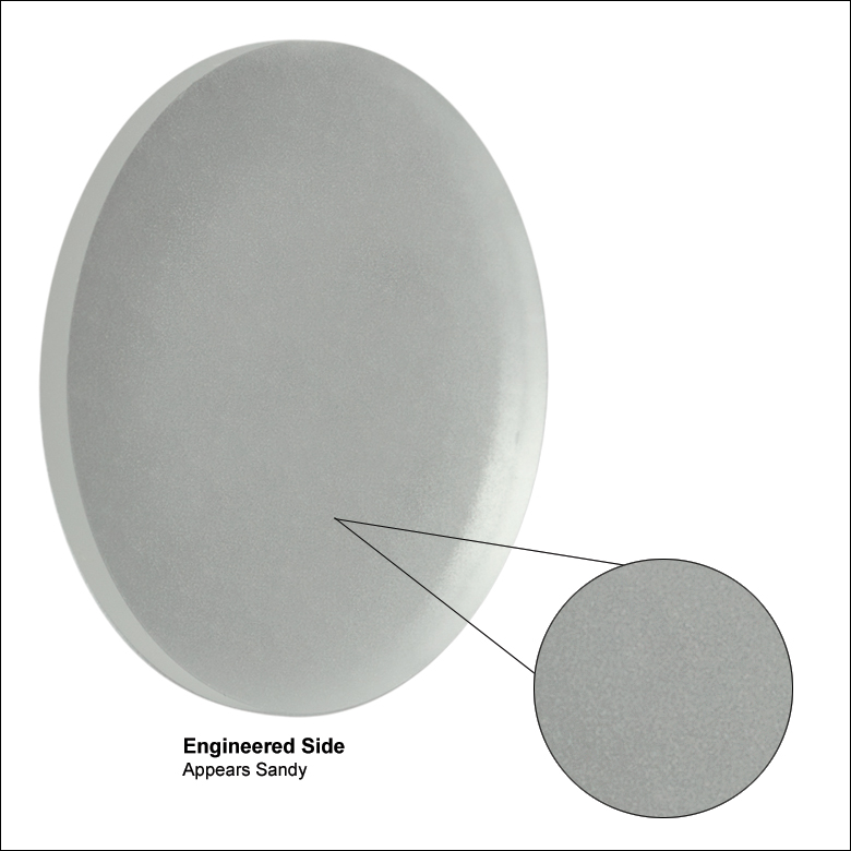
- Ø1" Engineered Diffusers®
- ZEONOR Polymer Substrate
- Circle, Square, or Line Pattern Diffusers
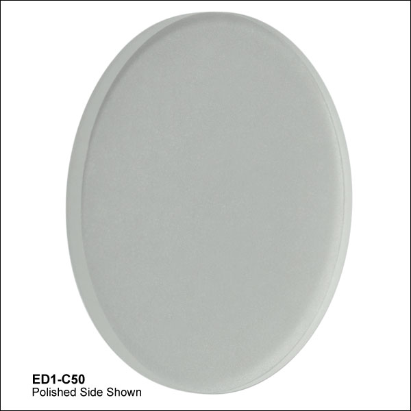
Unmounted optics are ideal for applications that are tight on space or that need added mounting flexibility. These Ø1" Unmounted Polymer Engineered Diffusers are commonly used in SM1-threaded (1.035"-40) lens tubes. The optic should be oriented so that incident light hits the engineered surface first.

 Zoom
Zoom
- Ø1" Engineered Diffusers® in SM1-Threaded Mounts
- ZEONOR Polymer Substrate
- Circle, Square, or Line Pattern Diffusers
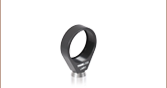
These Mounted Engineered Diffusers are the same as their unmounted counterparts, but are set in an engraved mount with internal SM1-threading (1.035"-40). Mounted optics have the advantage that they are easy to identify and the optics are recessed in the mount so that they are better protected from contamination than unmounted optics. The optic should be oriented so that incident light hits the engineered surface first; when the optic is placed in its mount, this surface will face the retaining ring.

 Zoom
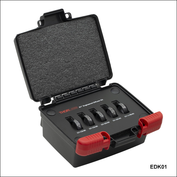
Zoom| Table G3.1 EDK01 Contents | |
|---|---|
| Item # | Description |
| ED1-C20-MD | Ø1" SM1-Mounted Polymer Engineered Diffuser, 20° Circle Pattern |
| ED1-C50-MD | Ø1" SM1-Mounted Polymer Engineered Diffuser, 50° Circle Pattern |
| ED1-S20-MD | Ø1" SM1-Mounted Polymer Engineered Diffuser, 20° Square Pattern |
| ED1-S50-MD | Ø1" SM1-Mounted Polymer Engineered Diffuser, 50° Square Pattern |
| ED1-L4100-MD | Ø1" SM1-Mounted Polymer Engineered Diffuser, 0.4° x 100° Line Pattern |
| - | Labeled Storage Box |
- Ø1" Engineered Diffusers® in SM1-Threaded Mounts
- ZEONOR Polymer Substrate
- Kit Includes Five Diffusers and a Storage Box
The EDK01 Polymer Engineered Diffuser® Kit includes five Ø1" mounted diffusers and a labeled storage box. These SM1-threaded mounts are engraved with the item number and a brief item description. Please see Table G3.1 for the contents of this diffuser kit.