 Products Home
Transverse Pockels Cell
- Transverse Pockels Cell for 700 - 1100 nm
- KD*P Electro-Optic Crystal
- Ideal as an Optical Shutter and Amplitude Modulator
PCT900
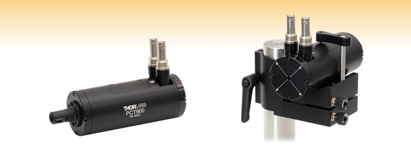
Transverse Pockels Cell
Application Idea
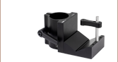
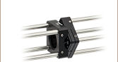
The PCT900 Pockels cell mounted on the C1513 Ø1.5" post kinematic V-Clamp mount.


Please Wait
| General Specifications | |
|---|---|
| Wavelength Range | 700 - 1100 nm |
| Clear Aperture | >Ø3 mm |
| Transmission | >90%a |
| Half-Wave Voltageb | 325 V @ 780 nm |
| Extinction Ratioc | >500:1 |
| Rise Time | <1 μs |
Features
- Wavelength Range of 700 - 1100 nm
- Transverse Pockels Cell
- Designed for Use as an Optical Shutter for Frequencies up to 250 kHz
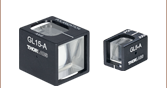
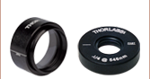
- Includes Glan-Laser Calcite Polarizer at Output
- Compatible Pockels Cell Driver Available Separately
Thorlabs' Transverse Pockels Cell offers fast, precise control of the output light's polarization direction as a function of applied voltage. It can be thought of as a voltage-controlled wave plate. This Pockels cell uses a potassium dideuterium phosphate (KD*P) crystal with the electric field applied in the transverse direction, that is perpendicular to the optical axis. Using the transverse orientation allows for lower voltages to be used than for longitudinal cells. Since the response is much faster than standard acousto-optic or liquid crystal devices, this Pockels cell is ideal for applications like fluorescence microscopy or other applications requiring rapid optical switching. This also allows the Pockels cell to be used as an optical shutter for frequencies from DC up to 250 kHz. A Glan-laser calcite polarizer is integrated into the Pockels cell at the output to facilitate the use of the cell as an amplitude modulator.
Click to Enlarge
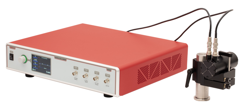
The PCD1K Pockels cell driver connected to the PCT900 Pockels cell, which has been mounted using the C1513 kinematic V-clamp mount.
The Pockels cell is an electro-optic device consisting of an electro-optic crystal through which light is transmitted. The polarization direction of the light is controlled by the voltage applied to the crystal. The Pockels effect explains the behavior of the Pockels cell: an applied constant or variable voltage (electric field) to the crystal produces linear changes in the birefringence of the crystal (in contrast to the Kerr Effect, which is quadratic with E). Applying a constant voltage allows the Pockels cell to operate as a voltage-controlled wave plate. This Pockels cell utilizes clamping to reduce the effects of piezoelectric ringing, allowing usage at high frequencies up to 250 kHz. For more information, see the Pockels Effect tab.
To download test data on a purchased Pockels cell, click on the red Docs icon ( ) below and enter its serial number in the "Download Serial Item Data" box; click here for a sample data sheet. Relevant data, such as the half-wave voltage, rise time, and how the extinction ratio varies with beam size can be found in the Graphs tab.
The PCT900 Pockels cell is not intended for use in laser cavities or as a Q-switch due to the approximately 6" device length and 3 mm clear aperture.
Mounting and Alignment
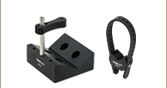
Aligning the Pockels cell will require x and y translation, as well as control of the rotational axes of roll, pitch, and yaw. This can be accomplished using a mount with six degrees of freedom, or via steering mirrors in kinematic mounts to adjust the beam and a mount for the Pockels cell that allows it to be rolled, like our V-mounts. The Pockels cell should be rotated to align the polarization of the input light with the desired axis of the calcite polarizer at the output end; white alignment lines on the input face near the SHV connectors can be used for this purpose. Reflected light escapes through the side window of the polarizer that is angled downwards when the Pockels cell is mounted with the SHV connectors oriented vertically. Detailed operation and alignment instructions can be found in the manual.
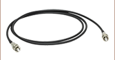
The end faces of the Pockels cell include tapped 4-40 holes for use in 30 mm cage systems. Rotating cage plates are available for integration into cage systems while allowing for rotational freedom in alignment of the Pockels cell. Thorlabs recommends using our Pockels cell driver with the PCT900 Pockels cell, which can be connected using SHV cables.
Handling Note
Thorlabs' Pockels cells should not be disassembled under any circumstances. The PCT900 is a "wet" cell that is filled with fluid to counteract the sensitivity to humidity of the KD*P crystal. The only approved cleaning method is the use of dry nitrogen to blow off external dust. Please contact Tech Support if you suspect the cell is damaged or contaminated.
Click to Enlarge
Click for Raw Data
The plot above shows the theoretical half-wave voltage of the PCT900 Pockels cell as a function of wavelength.
Click to Enlarge
Click for Raw Data
The typical extinction ratio of a PCT900 Pockels cell at 780 nm in relation to the beam diameter is shown in the plot above. The beam diameter is measured between points that are 1% of the peak power, which is 50% larger than the 1/e2 point for a Gaussian beam.
Click to Enlarge
Click for Raw Data
The measured rise time of the light through the PCT900 Pockels cell at a 1 kHz rep rate is shown in the plot above.
Pockels Effect
The Pockels effect is a linear electro-optic effect, where an electric field applied to a medium induces a change in the refractive index of the medium that is proportional to the strength of the applied electric field. This effect can only occur in crystals that are noncentrosymmetric, i.e. crystals that lack inversion symmetry. It is distinct from the Kerr effect, which is a nonlinear quadratic electro-optic effect that occurs in most materials and is proportional to the square of the electric field. A Pockels cell is an electro-optic device that is designed to make use of the Pockels effect for modulation purposes.
Some materials exhibit changes in their index of refraction dependent on the polarization of incident light, which is known as birefringence. These materials will split light into two orthogonal polarizations which experience different indices of refraction, known as ordinary and extraordinary rays. The changes that an applied electrical field will have on the refractive index of a crystal can be described using the electro-optic tensor, the form of which is determined by the symmetry of the crystal. Crystals with larger electro-optic coefficients in this tensor will more easily change the index of refraction due to the linear relationship with the applied electric field. This change in the refractive index will induce a phase shift, which will change the output polarization of incident light and can be used for amplitude modulation.
An important feature of a Pockels cell used for amplitude modulation is the half-wave voltage, which is the voltage required to produce a half-wave phase retardance corresponding to an amplitude change from minimum to maximum amplitude. This half-wave voltage is dependent on the wavelength of incident light and the orientation of the applied electric field. For longitudinal Pockels cells, which apply voltage parallel to the path of incident light, the length of the crystal is unrelated to the half-wave voltage; for transverse Pockels cells, which apply voltage perpendicular to the path of incident light, the half-wave voltage is proportional to the ratio of the electrode spacing to the length of the crystal. This means that for transverse Pockels cells, longer crystals can be used to lower the voltage needed for operation.
Potassium Dideuterium Phosphate (KD*P)
The electro-optic material used in the PCT900 Pockels cell is potassium dideuterium phosphate, also known as KD*P or DKDP. KD*P crystals belong to the 42m symmetry group, possessing the highest electro-optic coefficient of this group. Additionally, the transmission spectrum of KD*P extends further into the near infrared than its potassium dihydrogen phosphate (KDP) counterpart, due to the lower energy of oxygen-deuterium bond than KDP's oxygen-hydrogen bond. Clamping the crystal, which helps prevent piezoelectric ringing, results in a much smaller change in electro-optic coefficient as well. The disadvantage of using KD*P is that the crystal is hygroscopic and water soluble, so it is extremely sensitive to humidity and absorbs water vapor from the ambient environment. To combat this, the PCT900 Pockels cell is filled with insulating fluid and should not be disassembled under any circumstances.
| Posted Comments: | |
| No Comments Posted |