 Products Home / Active Optical Devices / Electro-Optic Modulators / Lithium Niobate Electro-Optic Modulators, Fiber-Coupled (765 nm - 1090 nm)
Lithium Niobate Electro-Optic Modulators, Fiber-Coupled (765 nm - 1090 nm)
- Up to 40 GHz Lithium Niobate (LiNbO3) Modulators
- 785 nm, 850 nm, or 1060 nm Wavelength Operation
- Annealed Proton-Exchange Waveguides
- Fiber-Coupled, High-Speed Modulation
LNY1010F
1060 nm 10 GHz Phase Modulator, FC/PC Connectors
LNY85D2A
850 nm 200 MHz Phase Modulator, FC/APC Connectors
LNX7840A
785 nm 40 GHz Intensity Modulator, FC/APC Connectors


Please Wait
Click to Enlarge
Figure 1.2 This operational diagram of an intensity modulator shows the waveguide (blue lines) splitting into two paths embedded in the surface of the LiNbO3 (green). The input light is first affected by the modulating RF drive voltage and then the DC bias voltage, as shown by the boxed yellow regions.
Click to Enlarge
Figure 1.1 The cross-section of an X-Cut LiNbO3 intensity modulator with annealed proton-exchange waveguide technology. The transverse electric (TE)-polarized mode is shown in the upper right.
Click to Enlarge
Figure 1.3 This operational diagram of a phase modulator shows the waveguide (blue line) as one through optical path embedded in the surface of the LiNbO3 (green). The input light is affected only by the modulating RF drive voltage, as shown by the boxed yellow region.
APE Waveguide Technology
APE waveguides are formed by exchanging lithium ions with a proton source such as H+. This is accomplished by submerging LiNbO3 in an acid melt rich in H+ ions, resulting in a change in the material's refractive index. Following this, the waveguides are annealed at high temperature to remove excess hydrogen from the exchanged region, leading to a stable waveguide. This annealing stage also transforms the step-index waveguides to gradient-index waveguides with greatly reduced single-mode propagation loss.
The APE process causes an increase in the extraordinary refractive index, but a decrease in the ordinary refractive index, meaning only the transverse electric (TE)-polarized mode is allowed to propagate. APE waveguides have significantly reduced photorefractive sensitivity compared to titanium-indiffused waveguides, enabling high-speed modulation at shorter wavelengths.
Features
- Intensity (LNX Series) or Phase (LNY Series) Modulators Available
- 785 nm, 850 nm, or 1060 nm Wavelength Operation
- Annealed Proton-Exchange Waveguides
- X-Cut Lithium Niobate (LiNbO3)
- Low Optical Insertion Loss: ≤5 dB (LNX Series) or ≤4 dB (LNY Series)
- Long-Term Bias Stability
- Reduced Photorefractive Sensitivity Compared to Titanium-Indiffused Waveguides
- Polarization-Maintaining (PM) Input and Output Fiber Pigtails
- FC/PC or FC/APC Fiber Connectors
Common Applications
- Quantum Optics
- High-Speed Telecommunications
- Test and Measurement
Thorlabs offers lithium niobate (LiNbO3) modulators for 785 nm, 850 nm, or 1060 nm wavelength applications. These high-performance devices are based on annealed proton-exchange (APE) waveguide technology, offer low optical insertion loss of ≤5 dB for intensity modulators or ≤4 dB for phase modulators, and are ideal for developing high-speed modulation systems.
The modulators on this page are fabricated from X-cut LiNbO3 (see Figure 1.1). For intensity modulators, which are denoted with the LNX prefix, a symmetrical design is employed to minimize frequency-chirp in the modulated signal. A Mach-Zehnder interferometer structure is used to allow modulation of the optical output power of the LiNbO3 optical intensity modulators, as shown by Figure 1.2. These devices include electrical connections for the modulation driving signal and for biasing the modulator. For phase modulators, items that are denoted with the LNY prefix, the X-cut waveguide structure allows for phase modulation of light while retaining a high polarization extinction ratio. An operational diagram of a phase modulator is shown in Figure 1.3. Since the phase modulators do not require biasing, these devices only include an electrical connection for the modulation driving signal. Please see the Pin Diagrams tab for more details.
The input and output fiber pigtails of the modulators are made from polarization-maintaining (PM) fiber and are terminated with FC/PC or FC/APC connectors. The narrow key of the fiber connector is aligned to the slow axis of the modulator. Please note that mixed FC/PC and FC/APC connectors can be provided upon request. For more information on custom configurations (e.g., connectors, wavelengths) and quotes, please contact Tech Support.
The performance of each modulator is factory tested, and a test result summary is included with each device. The test results and tabular data can be downloaded by clicking on the red Docs icon ( ) next to the Item # and entering your modulator's serial number under "Download Serial Item Data".
Our MX40G-850 fiber-optic, calibrated electrical-to-optical converter incorporates the LNX8540x modulators. For more information on custom integrated solutions and quotes for configurations that combine modulators with lasers, bias controllers, and amplifiers, please contact us.
785 nm Modulator Pin Diagram
Click to Enlarge
LNX7840F and LNX7840A 40 GHz Intensity Modulators Pin Diagram
Click to Enlarge
LNY7810F and LNY7810A 10 GHz Phase Modulators Pin Diagram
850 nm Modulator Pin Diagrams
Click to Enlarge
LNX8540F and LNX8540A 40 GHz Intensity Modulators Pin Diagram
Click to Enlarge
LNY8510F and LNY8510A 10 GHz Phase Modulators Pin Diagram
Click to Enlarge
LNY85D2F and LNY85D2A 200 MHz Phase Modulators Pin Diagram
1060 nm Modulator Pin Diagrams
Click to Enlarge
LNX1020F and LNX1020A 20 GHz Intensity Modulators Pin Diagram
Click to Enlarge
LNX1040F and LNX1040A 40 GHz Intensity Modulators Pin Diagram
Click to Enlarge
LNY10D2F and LNY10D2A 200 MHz Phase Modulators Pin Diagram
 Click to Enlarge
LNY1010F and LNY1010A 10 GHz Phase Modulators Pin Diagram
| Posted Comments: | |
Zeyan Zhang
(posted 2025-05-29 02:45:57.83) I'd like to use the LNY8510 at 918 nm. I know the spec says a max wavelength of 870 nm.Is their any negative effects? Thanks! tdevkota
(posted 2025-06-06 01:40:09.0) Thank you for contacting Thorlabs. We have successfully operated the LNX8540 at 940 nm, so based on that the LNY8510A should work at 918 nm as well. However, please note that we cannot guarantee all of the specs at that wavelength; the RF and DC Vπ scale with wavelength, so they will be higher at 918 nm. Ivan Ulyanov
(posted 2025-05-20 09:30:18.05) Hello,
I am interested in your LNX1020A phase modulator, but I have a question regarding its wavelength limitations. The specified operating range is 1030-1090 nm, but my application requires operation in the 1000-1050 nm range. Could you please clarify what limits the lower end of the wavelength range? Is the waveguide not guaranteed to be single-mode below 1030 nm, or is it simply that the Vπ voltage will be out of spec in that region?
Thank you in advance for your response. tdevkota
(posted 2025-05-21 04:19:27.0) Thank you for contacting Thorlabs. The LNX1020A is spec'd down to 1030 nm, so it may operate at 1000 nm, though with a few caveats. These are single-mode devices, but at shorter wavelengths there's a greater risk of exciting multiple modes, which could impact performance. The RF and DC Vπ scale with wavelength and would be lower at 1000 nm, meaning a larger modulation depth can be achieved (again, assuming no multi-mode behavior). That said, we haven’t tested the device outside of its specified wavelength range, so we can’t guarantee performance at 1000 nm. I have reached out to you directly to discuss this further. user
(posted 2025-03-28 03:31:56.403) Same question as Ozan Ari. ksosnowski
(posted 2025-03-28 06:08:00.0) Hello, thanks for reaching out to us. Unfortunately, it is not straightforward to use the fiber modulators as a polarization modulator. The PM fiber's axis is not aligned at 45degrees to the crystal, and the polarizers in our phase modulators could make this difficult even if the input axis were controllable. The fiber amplitude modulators also use Mach Zender configuration, so they cannot be readily applied as a polarization rotator like the freespace amplitude modulators can. Ozan ARI
(posted 2025-03-13 02:46:18.98) Greetings, can we use fiber-coupled LN electro-optic modulators to modulate the polarization similar to free-space electro-optic modulators? ksosnowski
(posted 2025-03-28 06:06:17.0) Hello Ozan, thanks for reaching out to us. Unfortunately, it is not straightforward to use the fiber modulators as a polarization modulator. The PM fiber's axis is not aligned at 45degrees to the crystal, and the polarizers in our phase modulators could make this difficult even if the input axis were controllable. The fiber amplitude modulators also use Mach Zender configuration, so they cannot be readily applied as a polarization rotator like the freespace amplitude modulators can. Menachem Polak
(posted 2025-03-12 01:10:00.083) Hello,
I want to operate the LNY7810A in with a DC value for a sort of Phase look element in a bigger optical system.
My question is in terms of power dissipation, if i give it a constant DC input where will all the power go to? will the LNY7810A burn? is it compatible to this kind of work? cdolbashian
(posted 2025-03-14 03:34:33.0) Thank you for reaching out to us with this inquiry! This type of application is potentially feasible, though I would like to hear more about your intended operating parameters. I have contacted you directly to discuss your application further. user
(posted 2024-05-21 19:13:14.483) Can you suggest suitable instrument/s for spectral characterization (observation of side bands & power in each side band; half wave voltage from drop in carrier amplitude etc.,) of phase modulator LNY1010A ? Is SA210-8B suitable for modulation frequencies of 2-3GHz? Please contact me by email srikanth@rrcat.gov.in. jpolaris
(posted 2024-06-03 07:44:44.0) Thank you for contacting Thorlabs. If the sideband spacing is greater than 67 MHz and less than 10 GHz, which are the resolution and free spectral range of SA210-8B, respectively, then the sidebands should be observable with that particular Fabry-Pérot interferometer. This assumes that the power transferred into these sidebands is appreciable enough to be detected by the photodiode in the interferometer. I have reached out to you directly to discuss further. Also, we have a page that goes into some detail about sideband measurement with a Fabry-Pérot interferometer located here: https://www.thorlabs.com/newgrouppage9.cfm?objectgroup_ID=3918&tabname=lab%20facts Paul Hamilton
(posted 2023-12-14 09:44:02.023) I'd like to use the LNY8510 at 894 nm. I know the spec says a max wavelength of 870 nm. Do you have any data for operation at 894 nm? Thanks! ksosnowski
(posted 2023-12-29 08:48:21.0) Hello Paul, thanks for reaching out to Thorlabs. We have successfully operated the LNX8540 at 940 nm. Based on this, we expect the LNY8510A should work at 894 nm. The caveat is that we cannot guarantee all of the specs (e.g., Vpi will be higher). 艾 传韡
(posted 2023-10-19 16:26:54.75) 您好,想咨询一下目前铌酸锂强度调制器为何在可见光波段无法实现呢 jpolaris
(posted 2023-10-23 12:29:47.0) Thank you for contacting Thorlabs. English translation: "Why does Thorlabs not offer any Lithium Niobate Intensity Modulators that work in the visible wavelength band?" We have plans to release a Lithium Niobate Intensity Modulator that will operate down to 775 nm in the near future. 775 nm is at the edge of what the current process used to make these particular Lithium Niobate Intensity Modulators is capable of producing. Below 775 nm, the Lithium Niobate begins to act strange, partially due to photorefractive damage, and partially due to nonlinear effects which begin to occur quickly as the wavelength gets shorter. |

 Zoom
ZoomApplications
- Analog Modulation Up to 40 GHz
- Quantum Optics
- Pulse Generation
- Test and Measurement
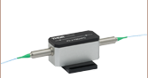
The LNX7840F and LNX7840A high-speed intensity modulators have FC/PC or FC/APC connectors, respectively, and provide up to 40 GHz of modulation over the 775 nm to 830 nm operating range. The RF port input connector is an Anritsu (V) female spark plug (1.85 mm compatible) connector.
| Item # | Info | Operating Wavelength |
Operating Frequency Rangea |
Optical Insertion Lossb |
Optical Return Loss |
Optical Extinction Ratio (@ DC)c |
Optical Input Powerd |
RF Vπe | Crystal Orientation |
Connector Type |
|---|---|---|---|---|---|---|---|---|---|---|
| LNX7840F | 775 nm - 830 nm | DC to 40 GHz (Min) | ≤5 dB (4.5 dB Typ.) |
≥30 dB | ≥20 dB | ≤20 mW | ≤4.8 V (4.0 V Typ.) |
X-Cut | FC/PC | |
| LNX7840A | FC/APC |

 Zoom
ZoomApplications
- Quantum Optics
- Frequency Modulation
- Spectrum Broadening
- Laser Stabilization
- Coherent Communications
- Test and Measurement
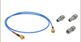
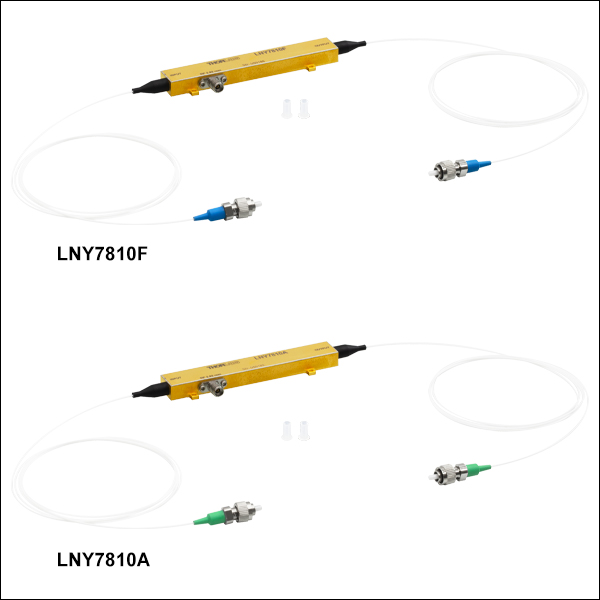
The LNY7810F and LNY7810A high-speed phase modulators have FC/PC or FC/APC connectors, respectively, and provide up to 10 GHz of modulation over the 765 nm to 805 nm operating range. The RF port input connector is a field-replaceable 2.92 mm female connector.
| Item # | Info | Operating Wavelength |
Operating Frequency Rangea |
Optical Insertion Lossb |
Optical Return Loss |
Polarization Extinction Ratio (@ DC)c |
Optical Input Powerd |
RF Vπe | Crystal Orientation |
Connector Type |
|---|---|---|---|---|---|---|---|---|---|---|
| LNY7810F | 765 nm - 805 nm | DC to 10 GHz (Min) | ≤4 dB (3 dB Typ.) |
≥30 dB | ≥20 dB | ≤25 mW | ≤5.2 V (4.2 V Typ.) |
X-Cut | FC/PC | |
| LNY7810A | FC/APC |

 Zoom
ZoomApplications
- Analog Modulation Up to 40 GHz
- WDM Transmission
- Quantum Optics
- High-Speed Telecommunications
- Test and Measurement
The LNX8540F and LNX8540A high-speed intensity modulators have FC/PC or FC/APC connectors, respectively, and provide up to 40 GHz of modulation over the 830 nm to 870 nm operating range. The RF port input connector is a 1.85 mm female connector.
| Item # | Info | Operating Wavelength |
Operating Frequency Range |
Optical Insertion Lossa |
Optical Return Loss |
Optical Extinction Ratio (@ DC)b |
Optical Input Powerc |
RF Vπd | Crystal Orientation |
Connector Type |
|---|---|---|---|---|---|---|---|---|---|---|
| LNX8540F | 830 nm - 870 nm | DC to 40 GHz (Min) | ≤5 dB (4.5 dB Typ.) |
≥30 dB | ≥20 dB | ≤25 mW | ≤5.3 V (4.8 V Typ.) |
X-Cut | FC/PC | |
| LNX8540A | FC/APC |

 Zoom
Zoom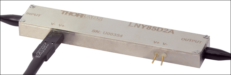
Click to Enlarge
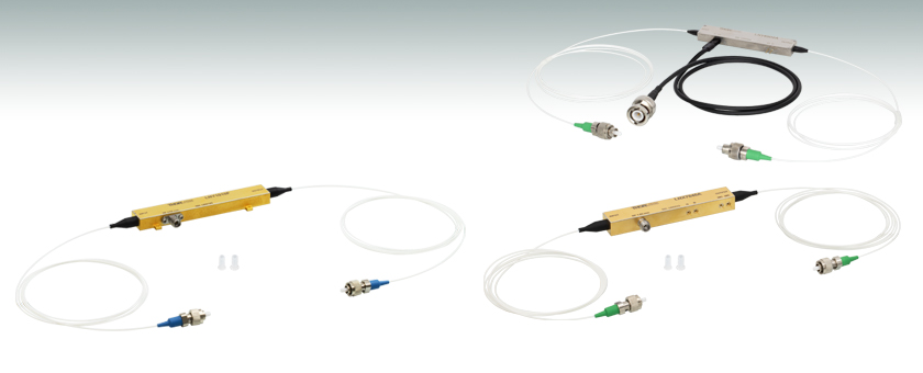
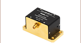
Figure G4.1 The LNY85D2x series modulator shown here is connected for single-ended operation with the included RF modulator cable. When connecting the cable, make sure to align the side of the 2-pin receptacle marked with the arrow and "-" to "V-" on the modulator.
Applications
- Quantum Optics
- Frequency Modulation
- Spectrum Broadening
- Laser Stabilization
- Coherent Communications
- Test and Measurement
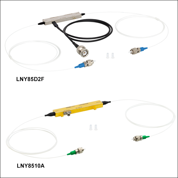
The LNY85D2x and LNY8510x Phase Modulators provide up to either 200 MHz or 10 GHz of modulation for wavelengths from 830 to 870 nm, respectively. Both the 200 MHz and 10 GHz modulators are available with either FC/PC or FC/APC connectors. The RF port input connector pins on the LNY85D2x modulators can be driven single-ended (connecting to one set of pins) or differentially (connecting both pin sets); a separate 20" BNC female to 2-pin receptacle cable is included with these modulators. For the LNY8510x modulators, the RF port input connector is a field-replaceable 2.92 mm female connector.
| Item # | Info | Operating Wavelength |
Operating Frequency Range |
Optical Insertion Lossa |
Optical Return Loss |
Polarization Extinction Ratio (@ DC)b |
Optical Input Powerc |
RF Vπ | Crystal Orientation |
Connector Type |
|---|---|---|---|---|---|---|---|---|---|---|
| LNY85D2F | 830 nm - 870 nm | DC to 200 MHz (Min) | ≤4 dB (3 dB Typ.) |
≥30 dB | ≥20 dB | ≤25 mW | ≤1.5 V (1.3 V Typ.)d |
X-Cut | FC/PC | |
| LNY85D2A | FC/APC | |||||||||
| LNY8510F | DC to 10 GHz (Min) | ≤4 dB (3 dB Typ.) |
≥30 dB | ≥20 dB | ≤25 mW | ≤5.2 V (4.8 V Typ.)e |
X-Cut | FC/PC | ||
| LNY8510A | FC/APC |

 Zoom
ZoomApplications
- Analog Modulation Up to 40 GHz
- RF-Over-Fiber (RFOF) and Microwave Photonics
- Pulse Generation for Ytterbium-Doped Fiber Amplifiers (YDFA)
- Quantum Optics
- High-Speed Telecommunications
- Test and Measurement
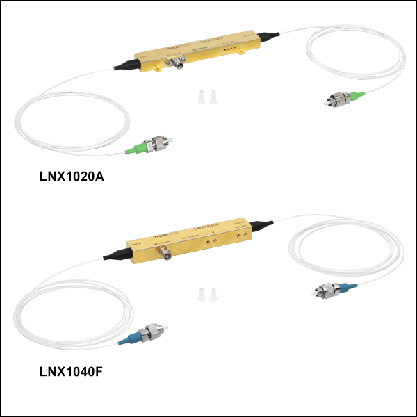
The LNX1020x and LNX1040x high-speed intensity modulators provide up to 20 GHz or 40 GHz, respectively, of modulation over the 1030 nm to 1090 nm operating range. Both the 20 GHz and 40 GHz modulators are available with either FC/PC or FC/APC connectors. The RF port input connector is a field-replaceable 2.92 mm female connector for the LNX1020x or an Anritsu (V) female spark plug (1.85 mm compatible) connector for the LNX1040x.
| Item # | Info | Operating Wavelength |
Operating Frequency Rangea | Optical Insertion Lossb |
Optical Return Loss |
Optical Extinction Ratio (@ DC)c |
Optical Input Powerd |
RF Vπe | Crystal Orientation |
Connector Type |
|---|---|---|---|---|---|---|---|---|---|---|
| LNX1020F | 1030 nm - 1090 nm | DC to 20 GHz (Min) | ≤5 dB (4.5 dB Typ.) |
≥30 dB | ≥20 dB | ≤350 mW | ≤4.5 V (4.0 V Typ.) |
X-Cut | FC/PC | |
| LNX1020A | FC/APC | |||||||||
| LNX1040F | DC to 40 GHz (Min) | ≤4.2 V (3.9 V Typ.) |
FC/PC | |||||||
| LNX1040A | FC/APC |

 Zoom
ZoomApplications
- Quantum Optics
- Frequency Modulation
- Spectrum Broadening
- Laser Stabilization
- Coherent Communications
- Test and Measurement
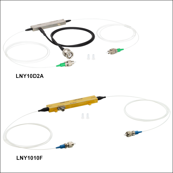
The LNY10D2x and LNY1010x Phase Modulators provide up to either 200 MHz or 10 GHz of modulation for wavelengths from 1030 nm to 1070 nm or 1030 nm to 1090 nm, respectively. Both the 200 MHz and 10 GHz modulators are available with either FC/PC or FC/APC connectors. The RF port input connector pins on the LNY10D2x modulators can be driven single-ended (unterminated) or differentially; a separate 20" BNC female to 2-pin receptacle cable is included with these modulators. For the LNY1010x modulators, the RF port input connector is a field-replaceable 2.92 mm female connector.
| Item # | Info | Operating Wavelength |
Operating Frequency Range |
Optical Insertion Lossa |
Optical Return Loss |
Polarization Extinction Ratio (@ DC)b |
Optical Input Powerc |
RF Vπ | Crystal Orientation |
Connector Type |
|---|---|---|---|---|---|---|---|---|---|---|
| LNY10D2F | 1030 nm - 1070 nm | DC to 200 MHz (Min) | ≤3.5 dB (3 dB Typ.) |
≥30 dB | ≥20 dB | ≤500 mW | ≤1.5 V (1.3 V Typ.)d |
X-Cut | FC/PC | |
| LNY10D2A | FC/APC | |||||||||
| LNY1010F | 1030 nm - 1090 nm | DC to 10 GHz (Min) | ≤3.5 dB (3 dB Typ.) |
≥30 dB | ≥20 dB | ≤100 mW | ≤6.8 V (6.2 V Typ.)e |
X-Cut | FC/PC | |
| LNY1010A | FC/APC |