 Products Home / Optical Elements / Optical Windows / Flat Windows / UV Fused Silica Textured Broadband Antireflective Windows
UV Fused Silica Textured Broadband Antireflective Windows

- Antireflective Performance Provided by Subwavelength
Surface Structures - 230 - 450 nm or 400 - 1100 nm Wavelength Range
- <0.25% Average Reflectance Over Wavelength Range
- Ideal for Applications Requiring Long-Term Beam Stability
Lower Reflectance Over a Broad Wavelength Range*
Higher Laser Damage Threshold*
Lower Angular Sensitivity*
*When Compared to Thorlabs' -UV, -A, -AB, and -B
Broadband Antireflective (BBAR) Coatings
W4101TUM
Ø1", 1.0 mm Thick,
2 AR Textured Sides,
230 - 450 nm,
Mounted
For a detailed comparison between the TU and T1 surfaces and Thorlabs' AR coatings, see the Comparison tab.
W40530T1
Ø1/2", 3.0 mm Thick,
2 AR Textured Sides, 400 - 1100 nm
W4105FT1
Ø1", 5.0 mm Thick,
1 AR Textured Side,
400 - 1100 nm
W40530T1M
Ø1/2", 3.0 mm Thick,
2 AR Textured Sides,
400 - 1100 nm,
Mounted


Please Wait
| Key Specificationsa | ||
|---|---|---|
| Item # Suffix | TU | T1 |
| Wavelength Range | 230 - 450 nm | 400 - 1100 nm |
| Damage Thresholdb | >30 J/cm2 at 355 nm, 10 ns, 10 Hz, Ø0.22 mm |
>30 J/cm2 at 532 nm, 10 ns, 10 Hz, Ø0.4 mm |
| Reflectance Over Wavelength Rangec |
Ravg < 0.25% | |
| Transmission Over Wavelength Ranged |
Tabs ≥ 98% | |
| Reflectance Data (Click for Graph) |
 Raw Data |
 Raw Data |
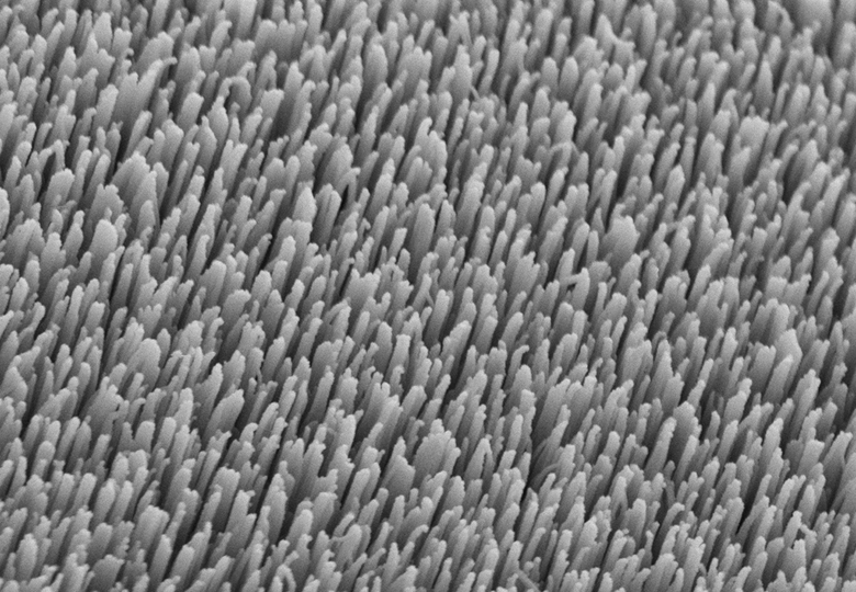
Click to Enlarge
Figure 1.1 SEM image showing a top-view of one of our UVFS nanostructured window surfaces.

Features
- Ø1/2", Ø1", and Ø1.5" Versions Available
- Antireflective (AR) Textured Surface on One or Both Sides
- AR Surfaces Designed for Wavelengths from 230 to 450 nm or 400 to 1100 nm
- <0.25% Average Reflectance per Antireflective Surface
- ≥98% Absolute Transmission for Windows with Two Textured Surfaces
- Unmounted and Mounted Options Available
- Ideal for UV, Visible, or NIR Applications Requiring Long-Term Beam Stability
- High Resistance to Laser-Induced Damage
Thorlabs' Textured Antireflective (AR) Windows are high-performance UV fused silica (UVFS) windows with nanostructured surfaces, resulting in ≥98% transmission over the specified wavelength range. These textured windows are available in two wavelength ranges: 230 - 450 nm for the UV regime and 400 - 1100 nm for the visible through the NIR. In contrast to AR coatings where thin layers are deposited on the substrate surface, these textured windows are created by removing material from the bulk substrate using our proprietary process, which has been optimized to fabricate subwavelength structures. Texturing the window surface results in an effective refractive index layer that suppresses reflected light over a broad wavelength range. An SEM image of the structured window surface is shown in Figure 1.1.
By including structured surfaces, these textured windows offer lower reflectance (<0.25% per surface) over a broader range of wavelengths and angles of incidence than is possible with thin-film coatings. Additionally, because the structured surfaces are part of the bulk optic, they have significantly higher laser damage thresholds (>30 J/cm2) compared to broadband antireflection (BBAR) coatings. As a result, these textured windows are less susceptible to damage during operation, providing more stable performance over time and making them ideal for applications that require long-term beam stability. Please see the Comparison tab for a detailed comparison of our TU and T1 textured surfaces to our BBAR coatings, and the App Highlight for more details on the technology and performance of our textured windows.
Windows designed for 230 - 450 nm are available with 1.0 mm thickness and 1/2" or 1" diameters. For the 400 - 1100 nm range, we offer 1.0 mm or 3.0 mm thick Ø1/2" windows, 1.0 mm or 5.0 mm thick Ø1" windows, and a 4.0 mm thick Ø1.5" vacuum window. Windows with two textured surfaces are available mounted or unmounted while windows with a single textured surface are only available unmounted. Please click the "Contact Me" button to discuss custom requests.
| Flat Window Selection Guide | |
|---|---|
| Wavelength Range | Substrate Material |
| 180 nm - 8.0 μm | Calcium Fluoride (CaF2) |
| 185 nm - 2.1 μm | UV Fused Silica |
| 200 nm - 5.0 μm | Sapphire |
| 200 nm - 6.0 μm | Magnesium Fluoride (MgF2) |
| 220 nm to >50 µm | CVD Diamond Windows |
| 230 nm - 1.1 µm | UV Fused Silica, Textured Antireflective Surface |
| 250 nm - 1.6 µm | UV Fused Silica, for 45° AOI |
| 250 nm - 26 µm | Potassium Bromide (KBr) |
| 300 nm - 3.0 µm | Infrasil® |
| 350 nm - 2.0 μm | N-BK7 |
| 600 nm - 16 µm | Zinc Selenide (ZnSe) |
| 1.0 - 1.7 µm | Infrasil®, Textured Antireflective Surface |
| 1.2 - 8.0 μm | Silicon (Si) |
| 1.9 - 16 μm | Germanium (Ge) |
| 2.0 - 5.0 μm | Barium Fluoride (BaF2) |
| V-Coated Laser Windows | |
Thorlabs also offers Infrasil®† textured windows with similar performance over the 1000 to 1700 nm wavelength range. We have a selection of High Precision Windows fabricated from various substrate materials for use in a large variety of laser and industrial applications. We also offer laser windows and wedged laser windows, which have AR V-coatings centered around commonly used laser wavelengths, and Brewster windows, which are used to eliminate p-polarized reflections.
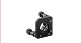
Mounting
The nanostructures providing the AR surface may be adversely affected by contact with mounting surfaces or retaining rings, causing localized performance degradation. To minimize the impacted areas, we recommend mounting these windows in an SM05- or SM1-threaded mount, such as the LMR05(/M) or LMR1(/M) Fixed Lens Mount, with an SM05LTRR or SM1LTRR Stress-Free Retaining Ring, respectively. Alternatively, options for Ø1/2" and Ø1" windows with texturing on both sides are available pre-mounted in either an SM05- (0.535"-40) or SM1-threaded (1.035"-40) housing, respectively. Please click the "Contact Me" button to discuss custom requests.
Got Questions?
Our engineers and expertise are here for you!

Jason Williamson
Director of Business Development
Thorlabs Spectral Works
If you are not sure whether our catalog textured windows meet your needs, we invite you to contact us to discuss your specific application, including custom or OEM requirements you may have.
Just press the button, and we'll get back to you within the next business day.

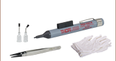
Handling Precautions and Cleaning
Thorlabs' Textured Windows could be contaminated or damaged by moisture, fingerprints, aerosols, or contact with any abrasive material. Latex gloves or a similar protective covering should be worn when handling the windows to prevent oil from fingers from reaching the structured surface. The unmounted windows should only be handled when necessary and always held by the sides using our TZ2 or TZ3 tweezers.
If the surface is contaminated, the windows may be cleaned by:
- Blowing off dust with clean air or nitrogen
- Rinsing with solvents, such as isopropyl alcohol, followed by clean air or nitrogen blow-drying
- Immersing in a basic solution (a mix of ammonium hydroxide and hydrogen peroxide) and/or an acidic solution (a mix of hydrochloric acid and hydrogen peroxide) followed by rinsing with isopropyl alcohol, and clean air or nitrogen blow-drying (unmounted windows only)
Standard cleaning methods will result in further contamination and thus should be avoided. Chemical cleaning methods are dangerous and should be performed with the proper equipment and safety practices.
†Infrasil is a registered trademark of Heraeus Quarzglas.
UV Fused Silica Textured Broadband Antireflective Windows
| Unmounted Item # | W4051TU | W4101TU | W40510T1 | W40530T1 | W41010T1 | W41050T1 | VPW42T1 |
|---|---|---|---|---|---|---|---|
| Mounted Item # | W4051TUM | W4101TUM | W40510T1M | W40530T1M | W41010T1M | W41050T1M | - |
| Wavelength Range | 230 nm - 450 nm | 400 nm - 1100 nm | |||||
| Diametera | 1/2" (12.7 mm) | 1" (25.4 mm) | 1/2" (12.7 mm) | 1" (25.4 mm) | 1.5" (38.1 mm) | ||
| Diameter Tolerancea | +0.0 / -0.2 mm | ||||||
| Thicknessa | 1.0 mm | 3.0 mm | 1.0 mm | 5.0 mm | 4.0 mm | ||
| Thickness Tolerancea | ±0.1 mm | ±0.3 mm | ±0.1 mm | ±0.3 mm | ±0.2 mm | ||
| Clear Aperture | ≥Ø10.16 mm | ≥Ø21.59 mm | ≥Ø10.16 mm | ≥Ø21.59 mm | ≥Ø32.0 mm | ||
| Parallelism | <3 arcmin | <5 arcsec | |||||
| Surface Quality | 10-5 Scratch-Dig | 20-10 Scratch-Dig | |||||
| Transmitted Wavefront Error | <λ/10 at 633 nm | <λ/8 at 633 nm |
|||||
| Substrate Material | UV Fused Silicab | ||||||
| Damage Threshold | >30 J/cm2 at 355 nm, 10 ns, 10 Hz, Ø0.22 mm | >30 J/cm2 at 532 nm, 10 ns, 10 Hz, Ø0.4 mm | |||||
| Reflectance Over Wavelength Rangec (Click for Plot) |
Ravg < 0.25% | Ravg < 0.25% | |||||
| Transmission Over Wavelength Ranged | Tabs ≥ 98% over Wavelength Range | ||||||
| Transmission Data (Click for Plot) |
Raw Data |
Raw Data |
Raw Data |
Raw Data |
Raw Data |
Raw Data |
|
Single-Sided UV Fused Silica Textured Broadband Antireflective Windows
| Item # | W4051FT1 | W4053FT1 | W4101FT1 | W4105FT1 |
|---|---|---|---|---|
| Wavelength Range | 400 - 1100 nm | |||
| Diameter | 1/2" (12.7 mm) | 1" (25.4 mm) | ||
| Diameter Tolerance | +0.0 / -0.2 mm | |||
| Thickness | 1.0 mm | 3.0 mm | 1.0 mm | 5.0 mm |
| Thickness Tolerance | ±0.1 mm | ±0.3 mm | ±0.1 mm | ±0.3 mm |
| Clear Aperture | ≥Ø10.16 mm | ≥Ø21.59 mm | ||
| Parallelism | <3 arcmin | |||
| Surface Quality | 10-5 Scratch-Dig | |||
| Transmitted Wavefont Error | <λ/10 at 633 nm | |||
| Substrate Material | UV Fused Silicaa | |||
| Damage Threshold | >30 J/cm2 at 532 nm, 10 ns, 10 Hz, Ø0.4 mm | |||
| Reflectance Over Wavelength Rangeb (Click for Plot) |
Ravg < 0.25% | |||
| Transmission Data (Click for Plot) |
Raw Data |
Raw Data |
Raw Data |
Raw Data |
Click to Enlarge
Figure 3.2 The TU and T1 surfaces' superior antireflective performance can be observed by eye. In this image, four 1.0 mm thick, UVFS windows were exposed to fluorescent ceiling lights, and reflections from the surfaces of the uncoated and A-coated windows can be seen in this photo of the four optics. A B-coated window was not included here since this coating is not intended to be used at visible wavelengths below 650 nm.
| Table 3.1 Specifications | ||
|---|---|---|
| Coating or Surface Designation (Item # Suffix) |
Wavelength Range |
Reflectance (Average)a |
| TU | 230 - 450 nm | <0.25% |
| -UV | 245 - 400 nm | <0.5% |
| -A | 350 - 700 nm | <0.5% |
| T1 | 400 - 1100 nm | <0.25% |
| -AB | 400 - 1100 nm | <1.0% |
| -B | 650 - 1050 nm | <0.5% |
Thorlabs' UV Fused Silica Windows with TU and T1 Textured Surfaces offer antireflective performance over a broad wavelength range, from 230 nm to 450 nm and 400 nm to 1100 nm, respectively. Figures 3.3 through 3.6 compare the performance of the TU and T1 textured surfaces to each of the following broadband antireflective (BBAR) coatings: 245 - 400 nm (designated as -UV), 350 - 700 nm (designated as -A), 400 - 1100 nm (designated as -AB), and 650 - 1050 nm (designated as -B).
The average reflectance of the TU surface, T1 surface, and BBAR coatings are listed in Table 3.1. Each provides good performance for angles of incidence (AOI) between 0° and 30° and a numerical aperture (NA) of 0.5.
Reflectance
Each performance plot shows the reflectance of the TU or T1 textured surface and one Thorlabs BBAR coating.
 Click to Enlarge
Figure 3.4 Comparison of Thorlabs' -A BBAR coating and the T1 textured surface reflectances. The blue arrow indicates the specified 350 - 700 nm wavelength range for the -A BBAR coating. The T1 surface wavelength range is indicated by the red arrow.
 Click to Enlarge
Figure 3.3 Comparison of Thorlabs' -UV BBAR coating and the TU textured surface reflectances. The blue arrow indicates the specified 245 - 400 nm wavelength range for the -UV BBAR coating. The TU surface wavelength range is indicated by the red arrow.
 Click to Enlarge
Figure 3.6 Comparison of Thorlabs' -B BBAR coating and the T1 textured surface reflectances. The blue arrow indicates the specified 650 - 1050 nm wavelength range for the -B BBAR coating. The T1 surface wavelength range is indicated by the red arrow.
 Click to Enlarge
Figure 3.5 Comparison of Thorlabs' -AB broadband BBAR coating and the T1 textured surface reflectances. The -AB coating and T1 surface both have a 400 - 1100 nm wavelength range, which is indicated by the black arrow.
Angle of Incidence (AOI) and Polarization
Each performance plot shows the s- and p-polarized reflectance at several AOI for the TU textured surface, -UV coating, T1 textured surface, -A coating, or -B coating when applied to a 1.0 mm thick UVFS window (Item #'s W4101TU, WG41010-UV, W41010T1, WG41010-A, and WG41010-B, respectively). With their low angular sensitivities, the TU and T1 surface reflectances are expected to stay relatively low over a large range of angles for both s- and p-polarized light. In contrast, the s-polarized reflectance values for the -UV, -A, and -B coatings are expected to rapidly rise with increasing AOI, while the p-polarized reflectance should show a slight decrease before increasing. The blue-shaded region indicates the specified wavelength range of each surface or coating.
| Surface or Coating Designation |
S-Polarized Reflectance (Click Here for an Excel Sheet with S-Polarized AOI Data) |
P-Polarized Reflectance (Click Here for an Excel Sheet with P-Polarized AOI Data) |
|---|---|---|
| TU |  Click to Enlarge |
 Click to Enlarge |
| -UV |  Click to Enlarge |
 Click to Enlarge |
| T1 |  Click to Enlarge |
 Click to Enlarge |
| -A |  Click to Enlarge |
 Click to Enlarge |
| -B |  Click to Enlarge |
 Click to Enlarge |
| Table 4.1 Damage Threshold Specifications | |
|---|---|
| Item # Suffix | Damage Threshold |
| TU | >30 J/cm2 at 355 nm, 10 ns, 10 Hz, Ø0.22 mm |
| T1 | >30 J/cm2 at 532 nm, 10 ns, 10 Hz, Ø0.4 mm |
Damage Threshold Data for Thorlabs' Textured Antireflective Windows
The specifications in Table 4.1 are measured data for Thorlabs' UV Fused Silica Windows with TU and T1 Textured Surfaces.
To demonstrate improved resistance to laser-induced damage, LIDT testing was performed on the W4101TU and W41010T1 textured windows at 355 nm and 532 nm, respectively, and for fluences up to 54 J/cm2 and 50 J/cm2, respectively. Damage sites, which appear red in the exposure histograms shown in Figures 4.2 and 4.3, are not observed on the TU textured window until exposure to a fluence of 38 J/cm2, and on the T1 textured window, 48 J/cm2. For a detailed description of the LIDT testing method, please see the Testing Method section of the Laser Induced Damage Threshold Tutorial below.
Click to Enlarge
Figure 4.2 Exposure Histogram for LIDT Testing on the W4101TU Textured Window
Measurement Beam Parameters: 355 nm, 10 ns, 10 Hz, Ø0.22 mm

Click to Enlarge
Figure 4.3 Exposure Histogram for LIDT Testing on the W41010T1 Textured Window Measurement Beam Parameters: 532 nm, 10 ns, 10 Hz, Ø0.4 mm
| Table 4.4 Laser Induced Damage Threshold Data | |||||||
|---|---|---|---|---|---|---|---|
| W4101TU LIDT Testing Dataa | W41010T1 LIDT Testing Datab | ||||||
| Fluence | # of Tested Locations |
Locations with Damage |
Locations Without Damage |
Fluence | # of Tested Locations |
Locations with Damage |
Locations Without Damage |
| 1 J/cm2 | 10 | 0 | 10 | 10 J/cm2 | 10 | 0 | 10 |
| 11 J/cm2 | 10 | 0 | 10 | 20 J/cm2 | 10 | 0 | 10 |
| 22 J/cm2 | 10 | 0 | 10 | 30 J/cm2 | 10 | 0 | 10 |
| 30 J/cm2 | 10 | 0 | 10 | 40 J/cm2 | 10 | 0 | 10 |
| 38 J/cm2 | 10 | 1 | 9 | 44 J/cm2 | 10 | 0 | 10 |
| 44 J/cm2 | 10 | 3 | 7 | 46 J/cm2 | 10 | 0 | 10 |
| 49 J/cm2 | 10 | 5 | 5 | 48 J/cm2 | 10 | 1 | 9 |
| 54 J/cm2 | 10 | 10 | 0 | 50 J/cm2 | 10 | 3 | 7 |
Laser Induced Damage Threshold Tutorial
The following is a general overview of how laser induced damage thresholds are measured and how the values may be utilized in determining the appropriateness of an optic for a given application. When choosing optics, it is important to understand the Laser Induced Damage Threshold (LIDT) of the optics being used. The LIDT for an optic greatly depends on the type of laser you are using. Continuous wave (CW) lasers typically cause damage from thermal effects (absorption either in the coating or in the substrate). Pulsed lasers, on the other hand, often strip electrons from the lattice structure of an optic before causing thermal damage. Note that the guideline presented here assumes room temperature operation and optics in new condition (i.e., within scratch-dig spec, surface free of contamination, etc.). Because dust or other particles on the surface of an optic can cause damage at lower thresholds, we recommend keeping surfaces clean and free of debris. For more information on cleaning optics, please see our Optics Cleaning tutorial.
Testing Method
Thorlabs' LIDT testing is done in compliance with ISO/DIS 11254 and ISO 21254 specifications.
First, a low-power/energy beam is directed to the optic under test. The optic is exposed in 10 locations to this laser beam for 30 seconds (CW) or for a number of pulses (pulse repetition frequency specified). After exposure, the optic is examined by a microscope (~100X magnification) for any visible damage. The number of locations that are damaged at a particular power/energy level is recorded. Next, the power/energy is either increased or decreased and the optic is exposed at 10 new locations. This process is repeated until damage is observed. The damage threshold is then assigned to be the highest power/energy that the optic can withstand without causing damage. A histogram such as that below represents the testing of one BB1-E02 mirror.
The photograph above is a protected aluminum-coated mirror after LIDT testing. In this particular test, it handled 0.43 J/cm2 (1064 nm, 10 ns pulse, 10 Hz, Ø1.000 mm) before damage.
| Example Test Data | |||
|---|---|---|---|
| Fluence | # of Tested Locations | Locations with Damage | Locations Without Damage |
| 1.50 J/cm2 | 10 | 0 | 10 |
| 1.75 J/cm2 | 10 | 0 | 10 |
| 2.00 J/cm2 | 10 | 0 | 10 |
| 2.25 J/cm2 | 10 | 1 | 9 |
| 3.00 J/cm2 | 10 | 1 | 9 |
| 5.00 J/cm2 | 10 | 9 | 1 |
According to the test, the damage threshold of the mirror was 2.00 J/cm2 (532 nm, 10 ns pulse, 10 Hz, Ø0.803 mm). Please keep in mind that these tests are performed on clean optics, as dirt and contamination can significantly lower the damage threshold of a component. While the test results are only representative of one coating run, Thorlabs specifies damage threshold values that account for coating variances.
Continuous Wave and Long-Pulse Lasers
When an optic is damaged by a continuous wave (CW) laser, it is usually due to the melting of the surface as a result of absorbing the laser's energy or damage to the optical coating (antireflection) [1]. Pulsed lasers with pulse lengths longer than 1 µs can be treated as CW lasers for LIDT discussions.
When pulse lengths are between 1 ns and 1 µs, laser-induced damage can occur either because of absorption or a dielectric breakdown (therefore, a user must check both CW and pulsed LIDT). Absorption is either due to an intrinsic property of the optic or due to surface irregularities; thus LIDT values are only valid for optics meeting or exceeding the surface quality specifications given by a manufacturer. While many optics can handle high power CW lasers, cemented (e.g., achromatic doublets) or highly absorptive (e.g., ND filters) optics tend to have lower CW damage thresholds. These lower thresholds are due to absorption or scattering in the cement or metal coating.
LIDT in linear power density vs. pulse length and spot size. For long pulses to CW, linear power density becomes a constant with spot size. This graph was obtained from [1].
Pulsed lasers with high pulse repetition frequencies (PRF) may behave similarly to CW beams. Unfortunately, this is highly dependent on factors such as absorption and thermal diffusivity, so there is no reliable method for determining when a high PRF laser will damage an optic due to thermal effects. For beams with a high PRF both the average and peak powers must be compared to the equivalent CW power. Additionally, for highly transparent materials, there is little to no drop in the LIDT with increasing PRF.
In order to use the specified CW damage threshold of an optic, it is necessary to know the following:
- Wavelength of your laser
- Beam diameter of your beam (1/e2)
- Approximate intensity profile of your beam (e.g., Gaussian)
- Linear power density of your beam (total power divided by 1/e2 beam diameter)
Thorlabs expresses LIDT for CW lasers as a linear power density measured in W/cm. In this regime, the LIDT given as a linear power density can be applied to any beam diameter; one does not need to compute an adjusted LIDT to adjust for changes in spot size, as demonstrated by the graph to the right. Average linear power density can be calculated using the equation below.

The calculation above assumes a uniform beam intensity profile. You must now consider hotspots in the beam or other non-uniform intensity profiles and roughly calculate a maximum power density. For reference, a Gaussian beam typically has a maximum power density that is twice that of the uniform beam (see lower right).
Now compare the maximum power density to that which is specified as the LIDT for the optic. If the optic was tested at a wavelength other than your operating wavelength, the damage threshold must be scaled appropriately. A good rule of thumb is that the damage threshold has a linear relationship with wavelength such that as you move to shorter wavelengths, the damage threshold decreases (i.e., a LIDT of 10 W/cm at 1310 nm scales to 5 W/cm at 655 nm):

While this rule of thumb provides a general trend, it is not a quantitative analysis of LIDT vs wavelength. In CW applications, for instance, damage scales more strongly with absorption in the coating and substrate, which does not necessarily scale well with wavelength. While the above procedure provides a good rule of thumb for LIDT values, please contact Tech Support if your wavelength is different from the specified LIDT wavelength. If your power density is less than the adjusted LIDT of the optic, then the optic should work for your application.
Please note that we have a buffer built in between the specified damage thresholds online and the tests which we have done, which accommodates variation between batches. Upon request, we can provide individual test information and a testing certificate. The damage analysis will be carried out on a similar optic (customer's optic will not be damaged). Testing may result in additional costs or lead times. Contact Tech Support for more information.
Pulsed Lasers
As previously stated, pulsed lasers typically induce a different type of damage to the optic than CW lasers. Pulsed lasers often do not heat the optic enough to damage it; instead, pulsed lasers produce strong electric fields capable of inducing dielectric breakdown in the material. Unfortunately, it can be very difficult to compare the LIDT specification of an optic to your laser. There are multiple regimes in which a pulsed laser can damage an optic and this is based on the laser's pulse length. The highlighted columns in the table below outline the relevant pulse lengths for our specified LIDT values.
Pulses shorter than 10-9 s cannot be compared to our specified LIDT values with much reliability. In this ultra-short-pulse regime various mechanics, such as multiphoton-avalanche ionization, take over as the predominate damage mechanism [2]. In contrast, pulses between 10-7 s and 10-4 s may cause damage to an optic either because of dielectric breakdown or thermal effects. This means that both CW and pulsed damage thresholds must be compared to the laser beam to determine whether the optic is suitable for your application.
| Pulse Duration | t < 10-9 s | 10-9 < t < 10-7 s | 10-7 < t < 10-4 s | t > 10-4 s |
|---|---|---|---|---|
| Damage Mechanism | Avalanche Ionization | Dielectric Breakdown | Dielectric Breakdown or Thermal | Thermal |
| Relevant Damage Specification | No Comparison (See Above) | Pulsed | Pulsed and CW | CW |
When comparing an LIDT specified for a pulsed laser to your laser, it is essential to know the following:
LIDT in energy density vs. pulse length and spot size. For short pulses, energy density becomes a constant with spot size. This graph was obtained from [1].
- Wavelength of your laser
- Energy density of your beam (total energy divided by 1/e2 area)
- Pulse length of your laser
- Pulse repetition frequency (prf) of your laser
- Beam diameter of your laser (1/e2 )
- Approximate intensity profile of your beam (e.g., Gaussian)
The energy density of your beam should be calculated in terms of J/cm2. The graph to the right shows why expressing the LIDT as an energy density provides the best metric for short pulse sources. In this regime, the LIDT given as an energy density can be applied to any beam diameter; one does not need to compute an adjusted LIDT to adjust for changes in spot size. This calculation assumes a uniform beam intensity profile. You must now adjust this energy density to account for hotspots or other nonuniform intensity profiles and roughly calculate a maximum energy density. For reference a Gaussian beam typically has a maximum energy density that is twice that of the 1/e2 beam.
Now compare the maximum energy density to that which is specified as the LIDT for the optic. If the optic was tested at a wavelength other than your operating wavelength, the damage threshold must be scaled appropriately [3]. A good rule of thumb is that the damage threshold has an inverse square root relationship with wavelength such that as you move to shorter wavelengths, the damage threshold decreases (i.e., a LIDT of 1 J/cm2 at 1064 nm scales to 0.7 J/cm2 at 532 nm):

You now have a wavelength-adjusted energy density, which you will use in the following step.
Beam diameter is also important to know when comparing damage thresholds. While the LIDT, when expressed in units of J/cm², scales independently of spot size; large beam sizes are more likely to illuminate a larger number of defects which can lead to greater variances in the LIDT [4]. For data presented here, a <1 mm beam size was used to measure the LIDT. For beams sizes greater than 5 mm, the LIDT (J/cm2) will not scale independently of beam diameter due to the larger size beam exposing more defects.
The pulse length must now be compensated for. The longer the pulse duration, the more energy the optic can handle. For pulse widths between 1 - 100 ns, an approximation is as follows:

Use this formula to calculate the Adjusted LIDT for an optic based on your pulse length. If your maximum energy density is less than this adjusted LIDT maximum energy density, then the optic should be suitable for your application. Keep in mind that this calculation is only used for pulses between 10-9 s and 10-7 s. For pulses between 10-7 s and 10-4 s, the CW LIDT must also be checked before deeming the optic appropriate for your application.
Please note that we have a buffer built in between the specified damage thresholds online and the tests which we have done, which accommodates variation between batches. Upon request, we can provide individual test information and a testing certificate. Contact Tech Support for more information.
[1] R. M. Wood, Optics and Laser Tech. 29, 517 (1998).
[2] Roger M. Wood, Laser-Induced Damage of Optical Materials (Institute of Physics Publishing, Philadelphia, PA, 2003).
[3] C. W. Carr et al., Phys. Rev. Lett. 91, 127402 (2003).
[4] N. Bloembergen, Appl. Opt. 12, 661 (1973).
| Posted Comments: | |
Ryan Thalman
(posted 2024-08-15 11:15:41.307) We would very much like to be able to buy a 2" diameter version of this.
Thanks!
Ryan cdolbashian
(posted 2024-08-26 09:34:16.0) Thank you for reaching out to us with this inquiry. A 2" version is something we are looking to add to our catalogue in the near future, though we do not have a specific date. For the time being though, I have contacted you directly to discuss a custom option. |

 Zoom
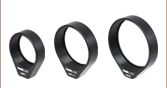
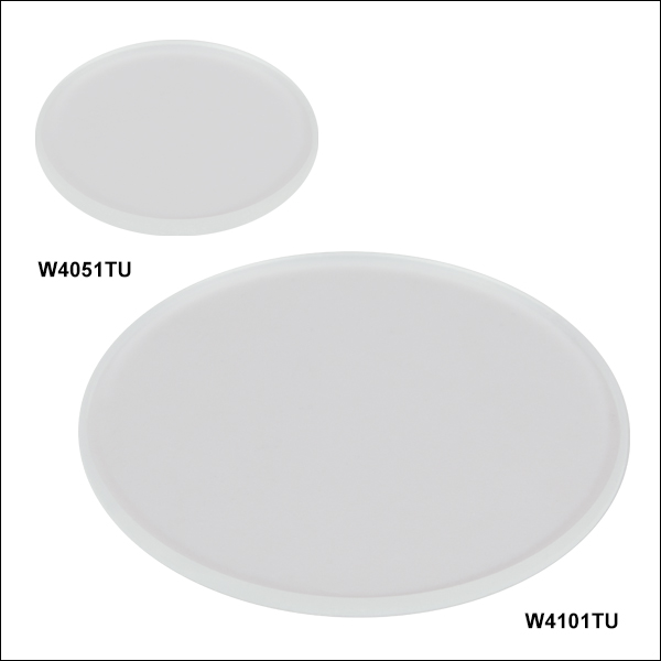
Zoom- UVFS Windows with Two Textured UV Antireflective Surfaces for 230 - 450 nm
- Ø1/2" and Ø1" Windows Available
- <0.25% Average Reflectance per Antireflective Surface
- ≥98% Absolute Transmission over Wavelength Range
These Ø1/2" and Ø1" unmounted windows feature two textured antireflective surfaces and are designed for use over the 230 - 450 nm wavelength range. The nanostructured surface of the window provides low reflectance (<0.25% per AR surface) and a high resistance to laser-induced damage. The absolute transmission for these windows is ≥98% over the entire design wavelength range. Please see the Specs tab for more information.

 Zoom
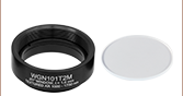
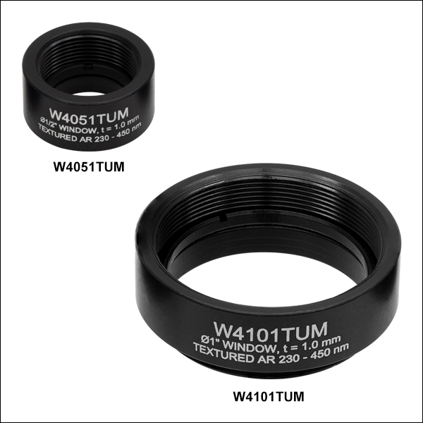
Zoom- Mounted UVFS Windows with Two Textured UV Antireflective Surfaces for 230 - 450 nm
- Ø1/2" and Ø1" Windows Available
- <0.25% Average Reflectance per Antireflective Surface
- ≥98% Absolute Transmission over Wavelength Range
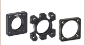
- SM05- (0.535"-40) or SM1- (1.035"-40) Threaded Housing
These Ø1/2" and Ø1" mounted windows are the same as their unmounted counterparts but are set in engraved housings with internal and external SM05 (0.535"-40) or SM1 (1.035"-40) threading. Mounted optics have the advantage that they are easy to identify and the optics are recessed in the mount so that they are better protected from contamination. The SM-threaded mounts are compatible with our line of SM-threaded lens tubes and enable easy integration with Thorlabs' optomechanics. Each Ø1/2" and Ø1" textured window comes with two SM05- or SM1-threaded end caps, respectively, to protect the textured surface. If replacement end caps are needed, we recommend using Item #s SM05CP1 and SM05CP2 for the W4051TUM window, and Item #s SM1CP1 and SM1CP2 for the W4101TUM window.

 Zoom
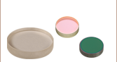
Zoom- UVFS Windows with Two Textured Broadband Antireflective Surfaces for 400 - 1100 nm
- Ø1/2", Ø1", and Ø1.5" Windows Available
- Vacuum-Compatible Version Available
- <0.25% Average Reflectance per Antireflective Surface
- ≥98% Absolute Transmission over Wavelength Range
These Ø1/2", Ø1", and Ø1.5" unmounted windows feature two textured antireflective surfaces and are designed for use over the 400 - 1100 nm wavelength range. The nanostructured surface of the window provides low reflectance (<0.25% per AR surface) and a high resistance to laser-induced damage. The absolute transmission for these windows is ≥98% over the entire design wavelength range. Please see the Specs tab for more information.
The Ø1.5" window is specifically designed to be compatible with our High-Vacuum CF Flange Viewports for Ø1.5" Optics, and is also compatible with the VC23FL empty vacuum flange. An untextured annulus on this optic enables the vacuum seal. The textured surface has a 1.26" diameter.

 Zoom
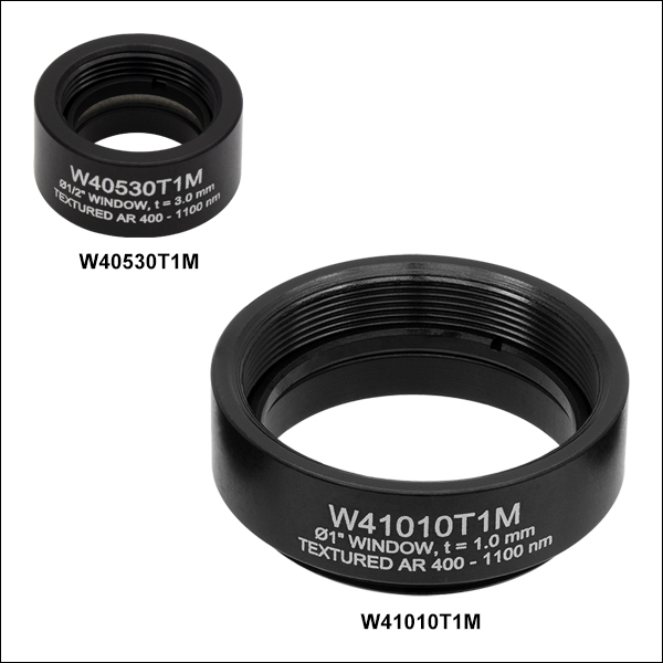
Zoom- Mounted UVFS Windows with Two Textured Broadband Antireflective Surfaces for 400 - 1100 nm
- Ø1/2" and Ø1" Windows Available
- <0.25% Average Reflectance per Antireflective Surface
- ≥98% Absolute Transmission over Wavelength Range
- SM05- (0.535"-40) or SM1- (1.035"-40) Threaded Housing
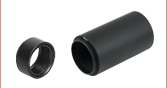
These Ø1/2" and Ø1" mounted windows are the same as their unmounted counterparts but are set in engraved housings with internal and external SM05 (0.535"-40) or SM1 (1.035"-40) threading. Mounted optics have the advantage that they are easy to identify and the optics are recessed in the mount so that they are better protected from contamination. The SM-threaded mounts are compatible with our line of SM-threaded lens tubes and enable easy integration with Thorlabs' optomechanics. Each Ø1/2" and Ø1" textured window comes with two SM05- or SM1-threaded end caps, respectively, to protect the textured surface. If replacement end caps are needed, we recommend using Item #s SM05CP1 and SM05CP2 for the Ø1/2" windows, and Item #s SM1CP1 and SM1CP2 for the Ø1" windows.

 Zoom
Zoom- UVFS Windows with One Textured Broadband Antireflective for 400 - 1100 nm
- Second Side of Window is Untextured and Uncoated
- Ø1/2" and Ø1" Windows Available
- Antireflective Surface: <0.25% Average Reflectance
These Ø1/2" and Ø1" unmounted windows feature a single textured antireflective surface and are designed for use over the 400 - 1100 nm wavelength range. The nanostructured surface of the window provides low reflectance (<0.25% per AR surface) and a high resistance to laser-induced damage while the other side of the window is left untreated for applications where the window may be exposed to non-ideal environmental conditions or conditions that may require frequent, traditional cleaning. An arrow on the edge of the window points toward the textured AR surface. Please see the Specs tab for more information.