 Products Home / Imaging Components / Optics for Microscopy / Microscopy Filter Cubes with Pre-Installed Fluorescence Filters
Microscopy Filter Cubes with Pre-Installed Fluorescence Filters
- Pre-Installed Filters Minimize Handling of Bare Optics
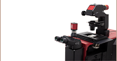
- Drop-In Compatibility with Select Olympus and Nikon Microscopes
- Matched Filter Sets Designed for Wavelength Ranges of Common Fluorophores
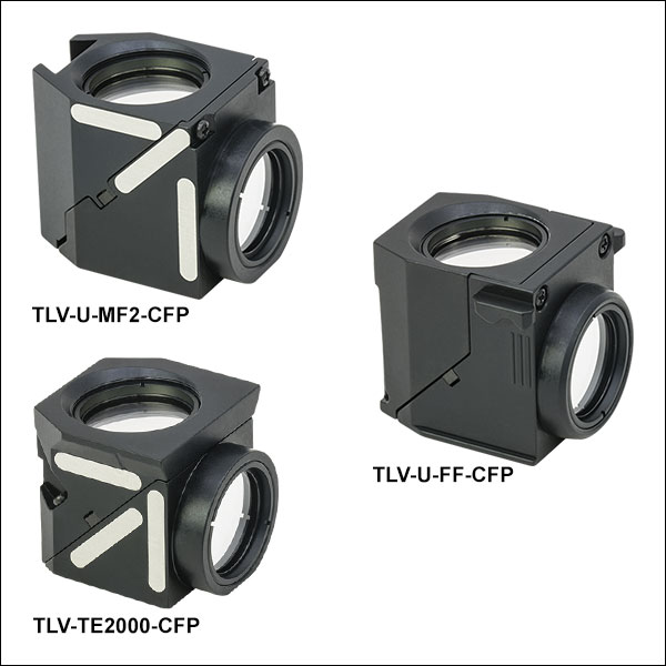
TLV-U-MF2-CFP
CFP Filter Cube for Olympus AX, BX2, and IX2 Microscopes
TLV-U-FF-GFP2
Alexa Fluor® 488 Filter Cube for Olympus BX3 and IX3 Microscopes
TLV-TE2000-TOM
tdTomato Filter Cube for Nikon TE2000 and Eclipse Ti


Please Wait
| Quick Links | |
|---|---|
| Fluorophorea | Excitation / Emission Wavelength |
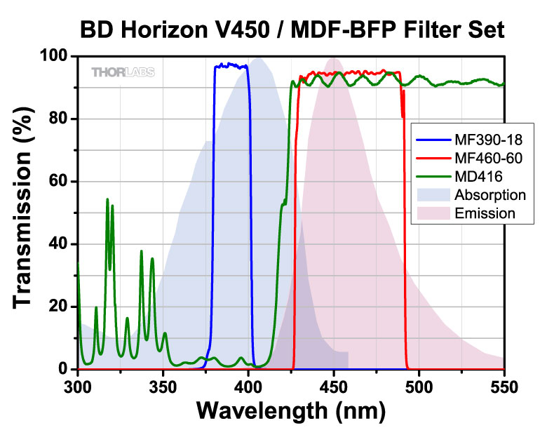
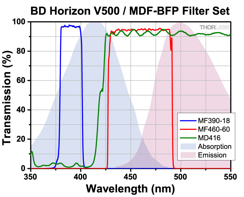
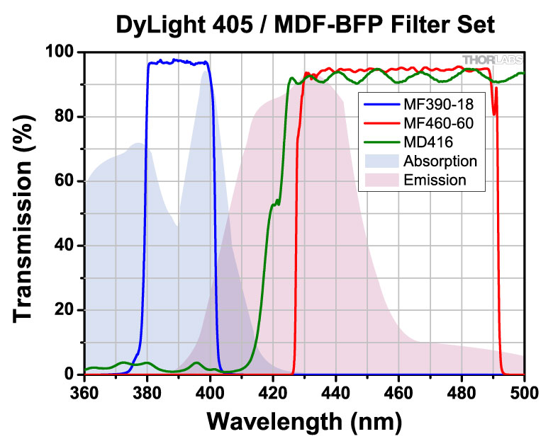
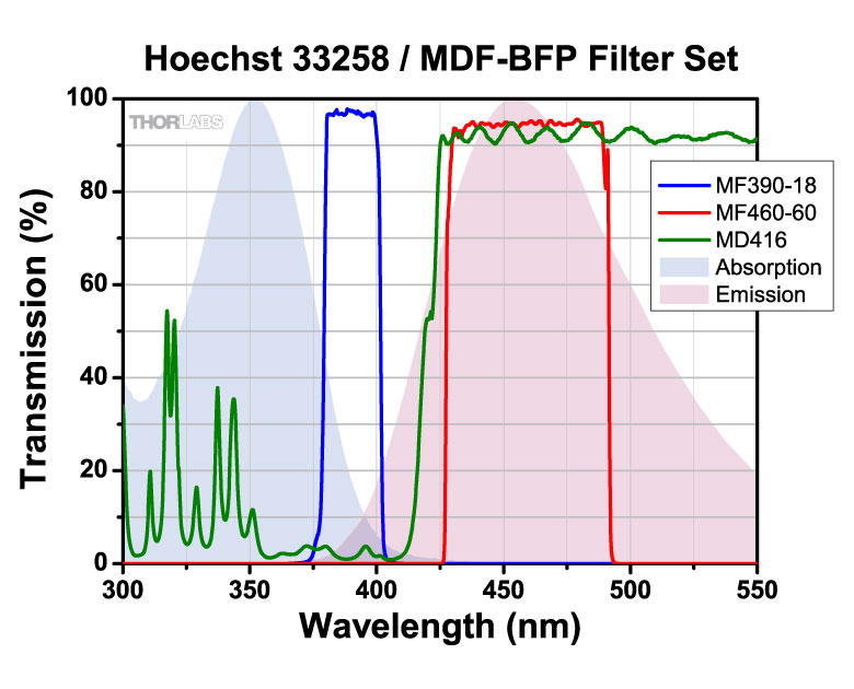
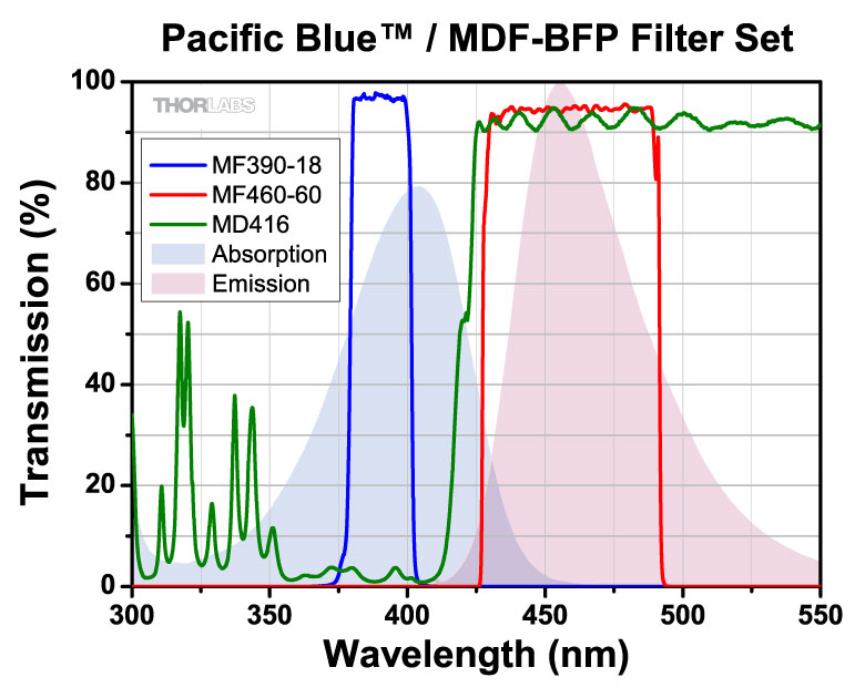
| BFP | 390 nm / 460 nm |
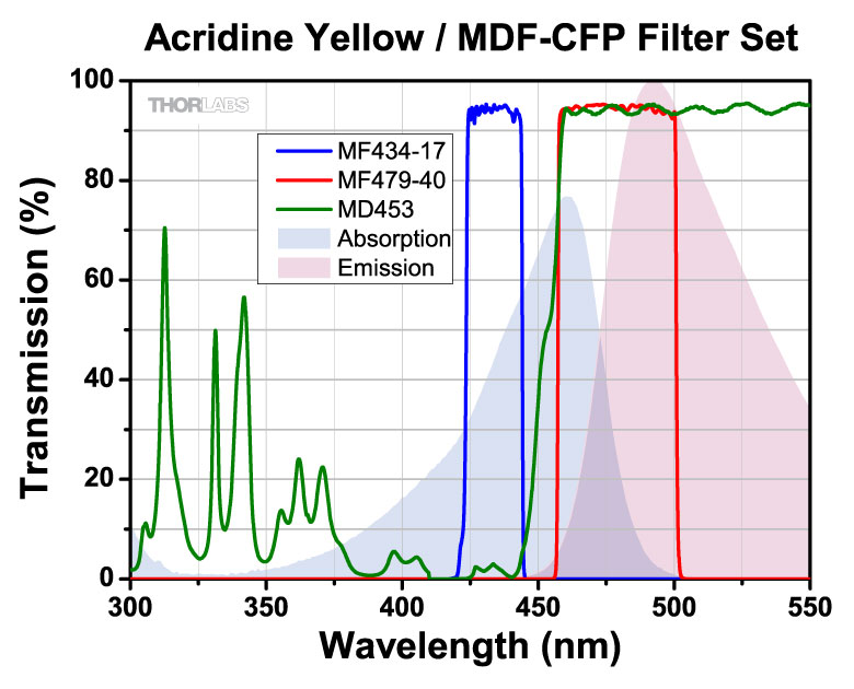
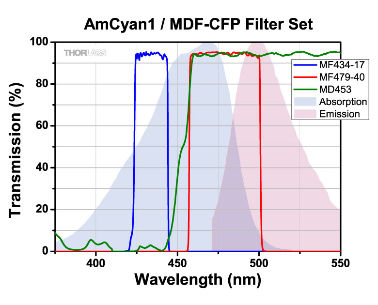
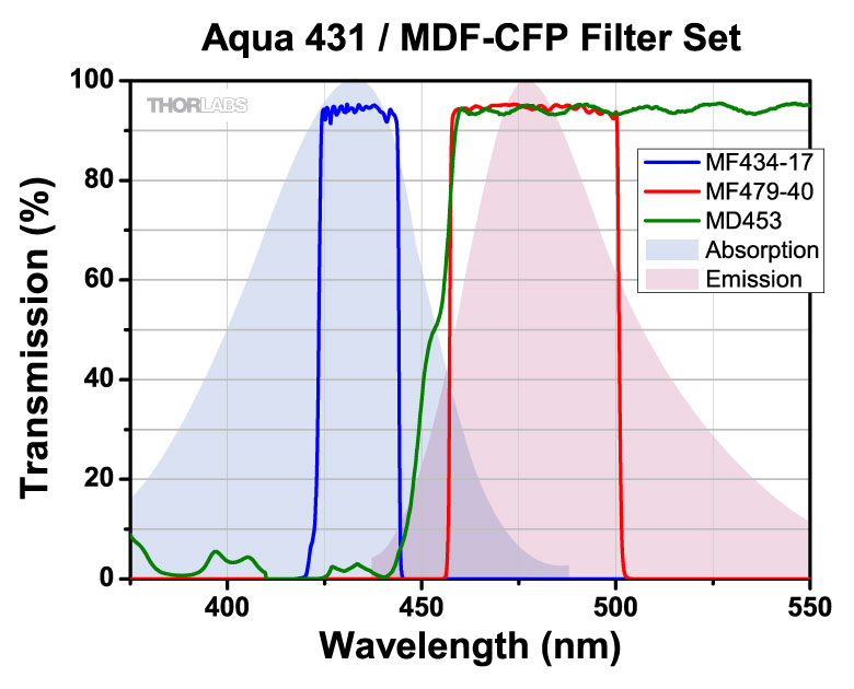
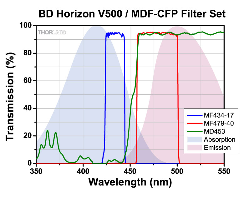
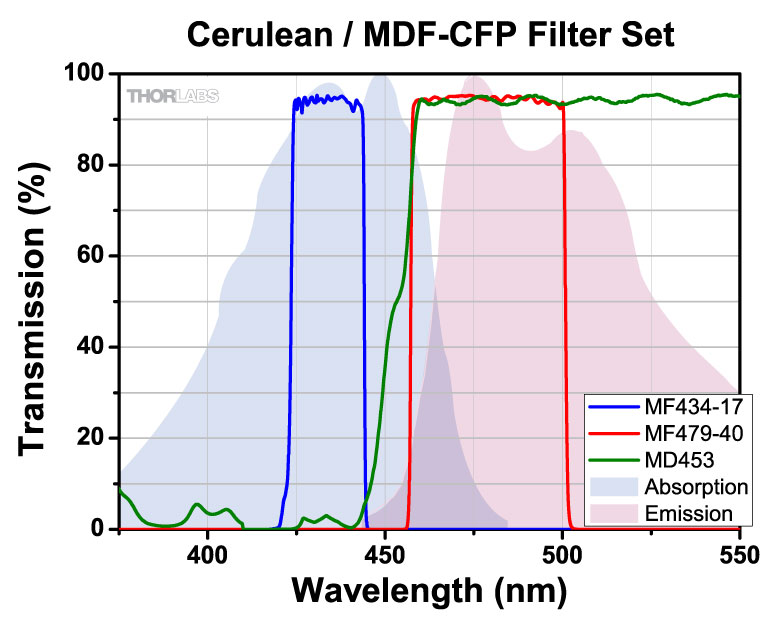
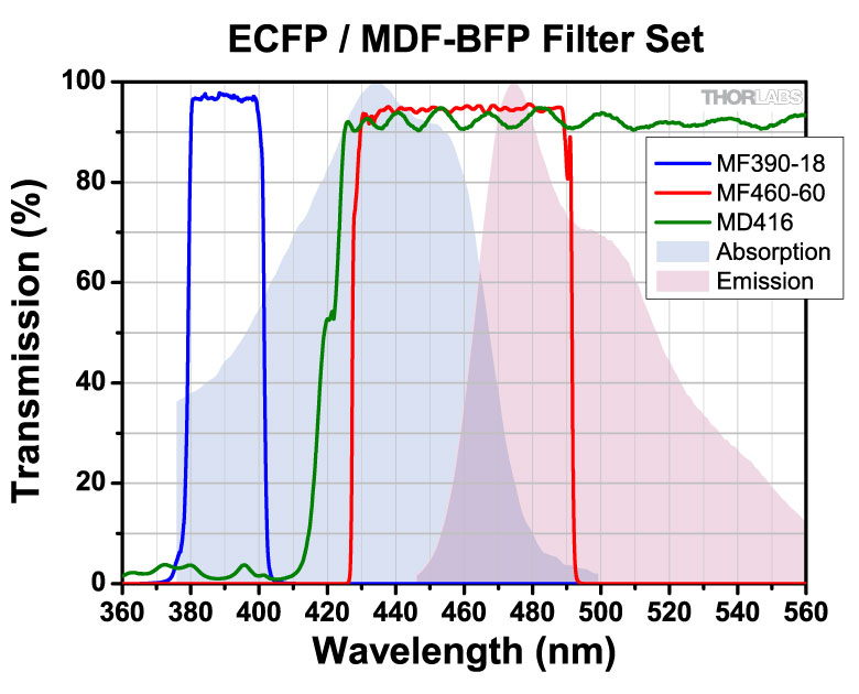
| CFP | 434 nm / 479 nm |
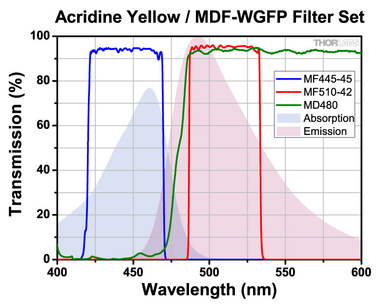
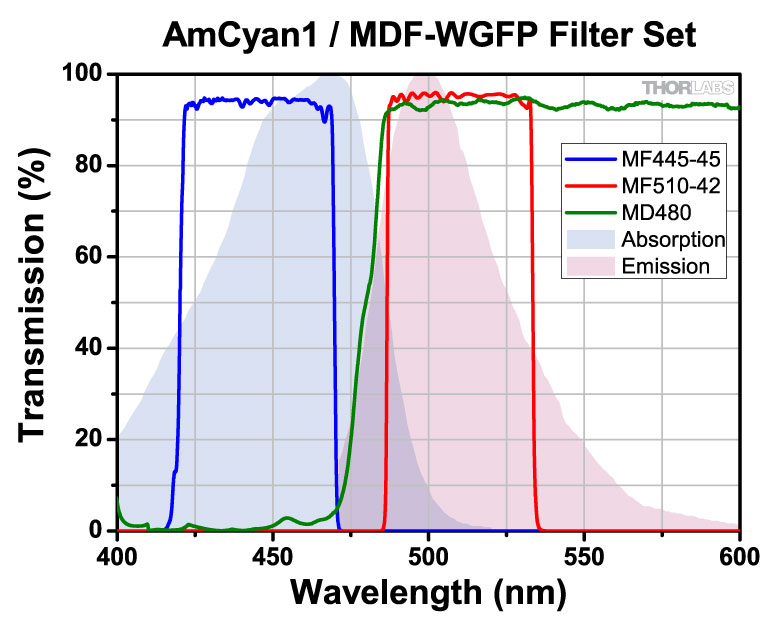
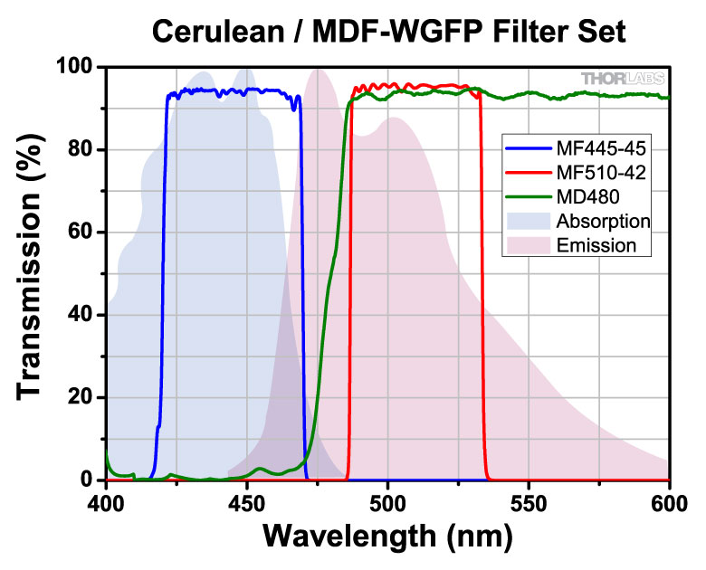
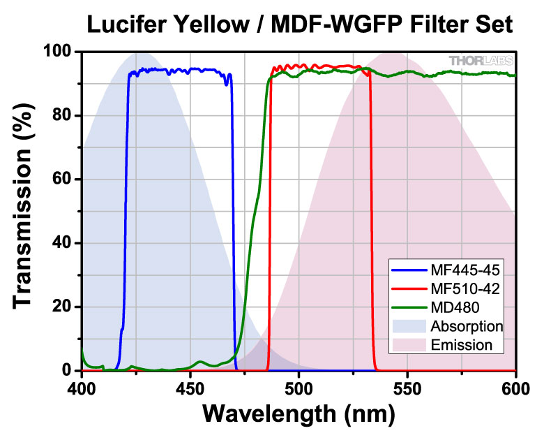
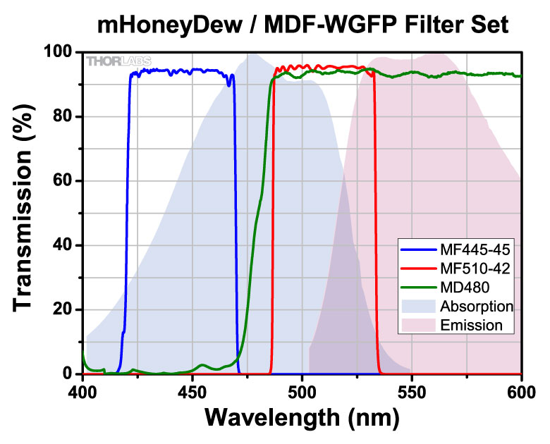
| Wild Type GFP | 445 nm / 510 nm |
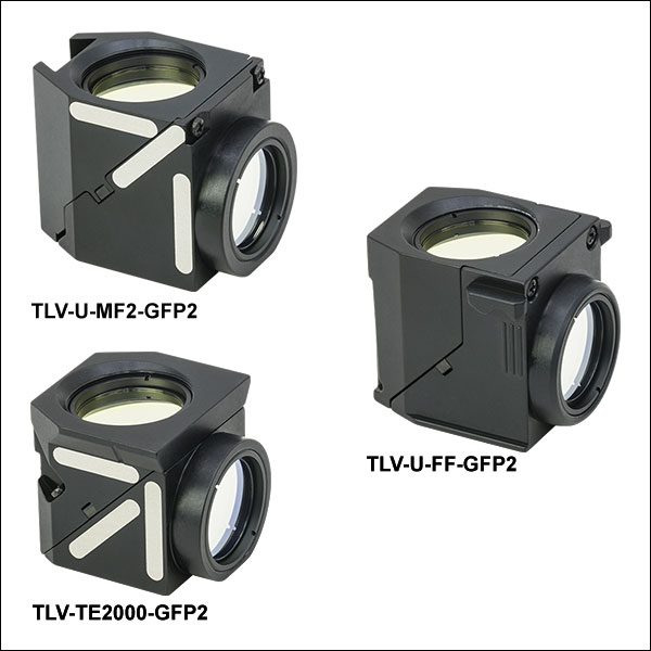
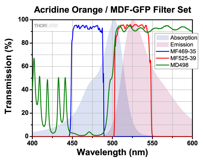
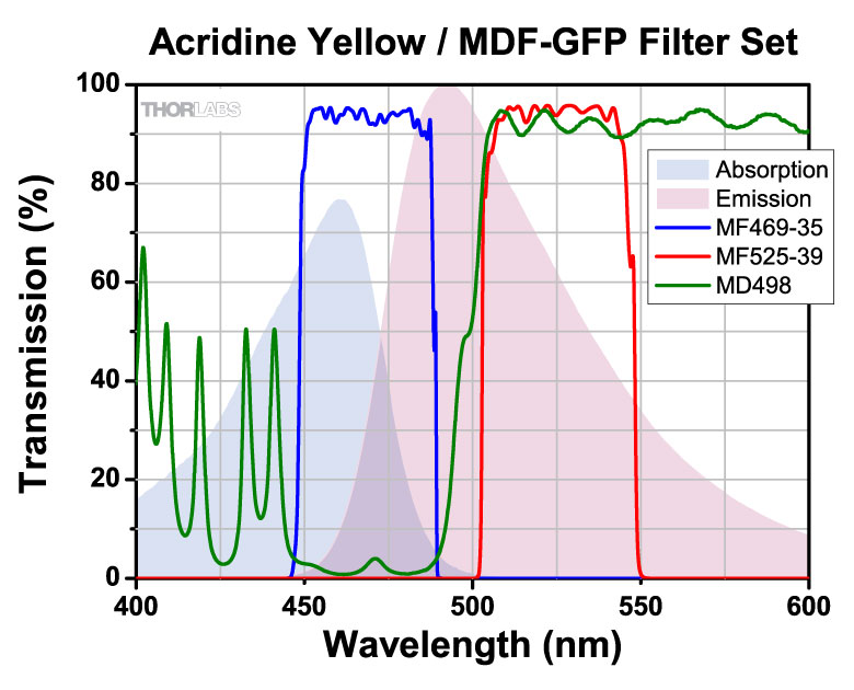
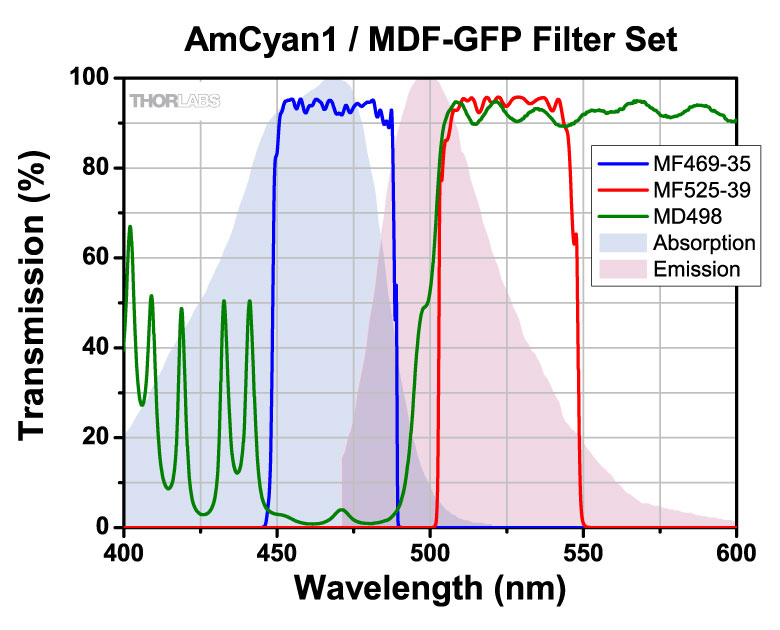
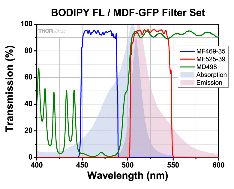
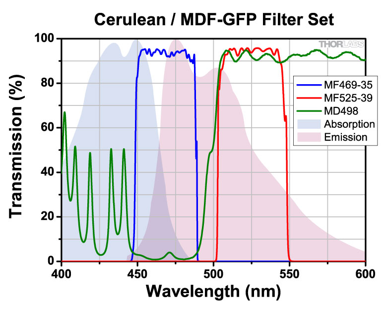
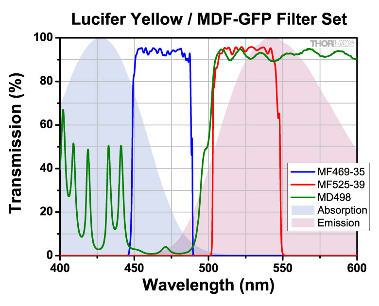
| GFP | 469 nm / 525 nm |
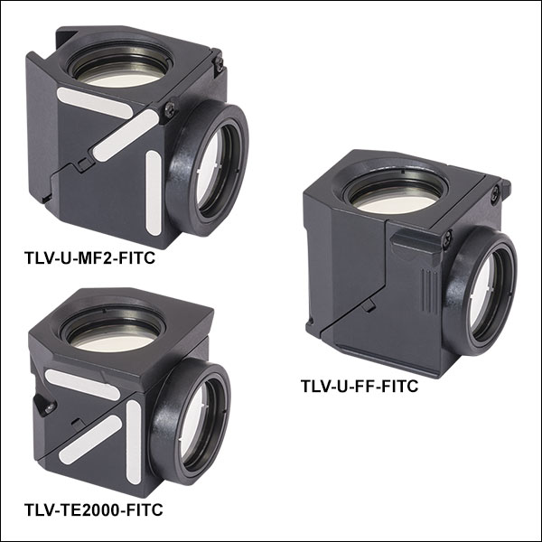
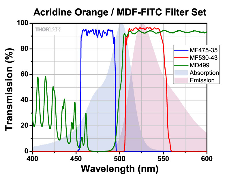
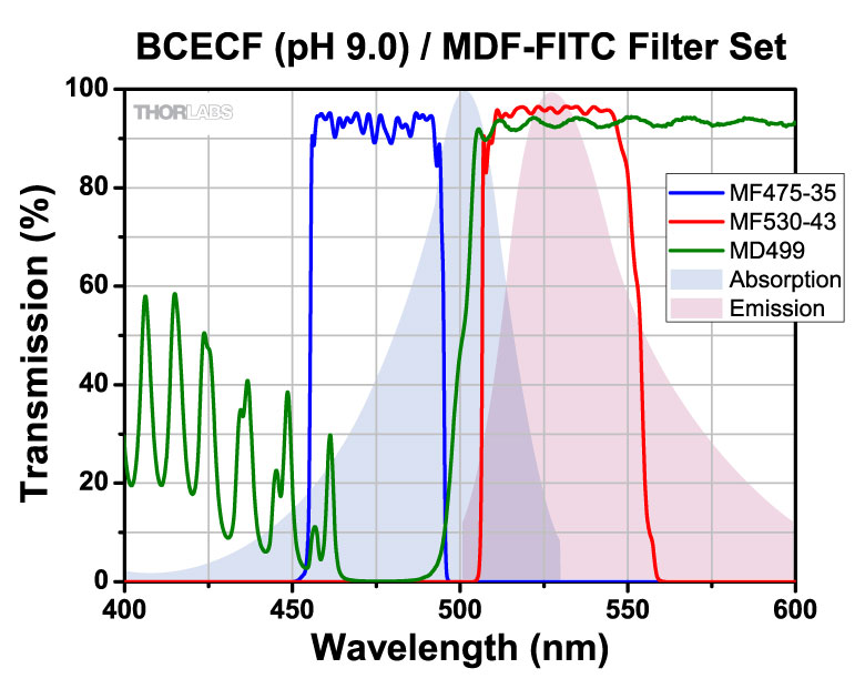
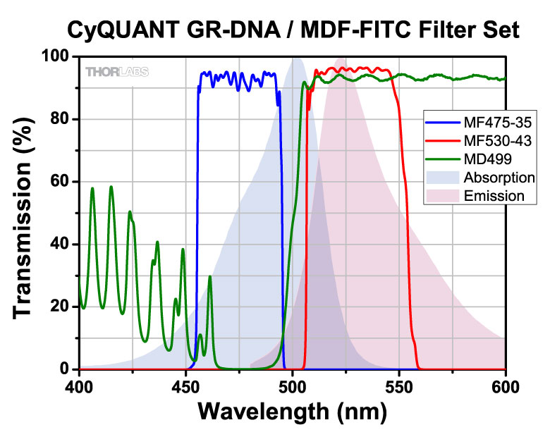
| FITC | 475 nm / 530 nm |
| Alexa Fluor® 488 | 482 nm / 520 nm |
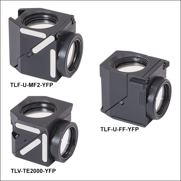
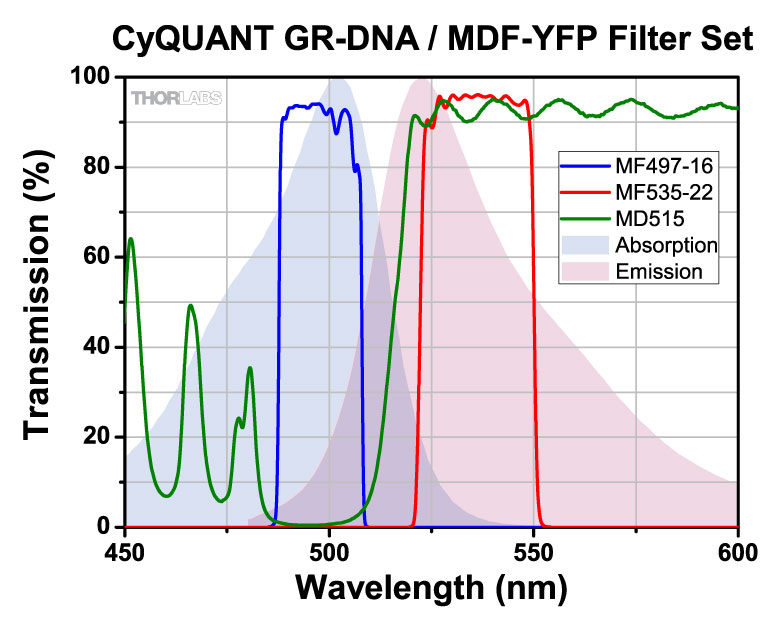
| YFP | 497 nm / 535 nm |
| tdTomato | 531 nm / 593 nm |
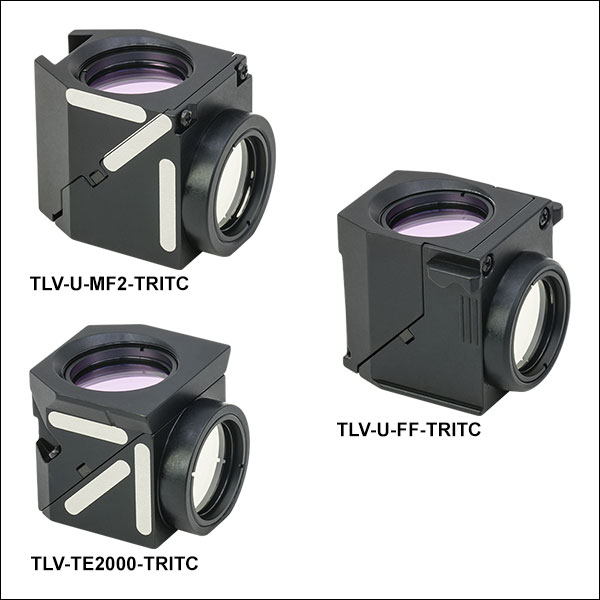
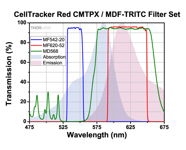
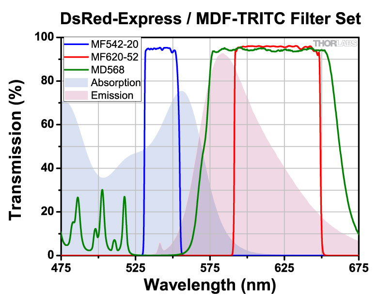
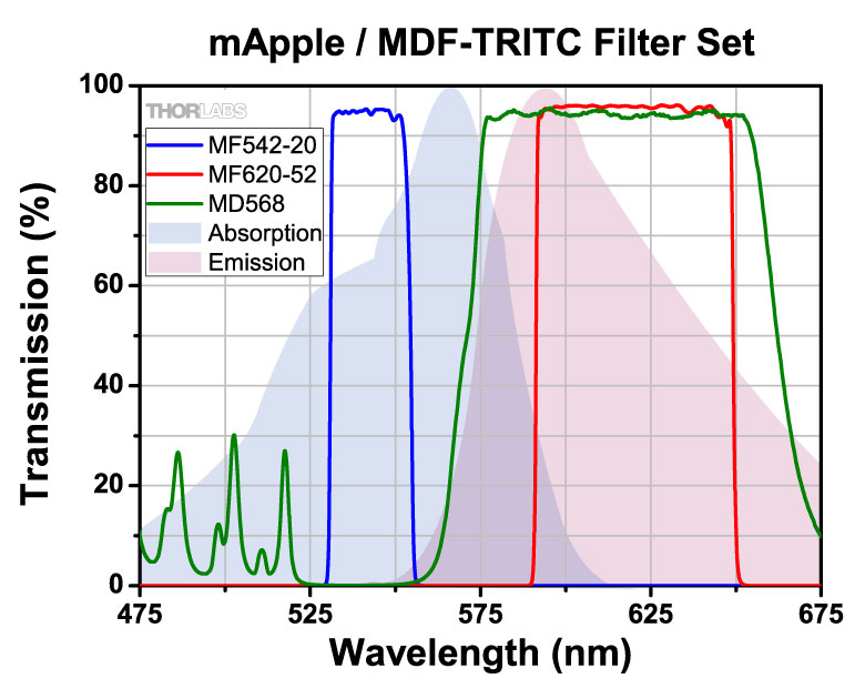
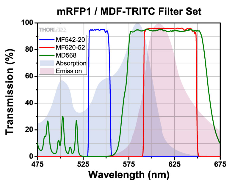
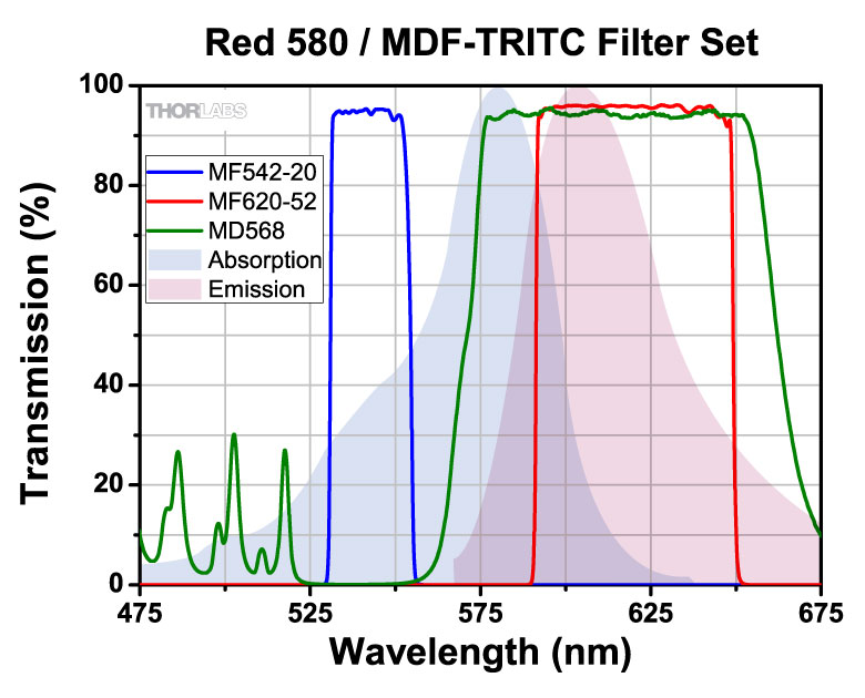
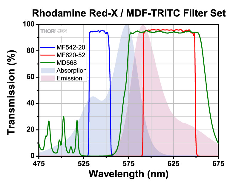
| TRITC | 542 nm / 620 nm |
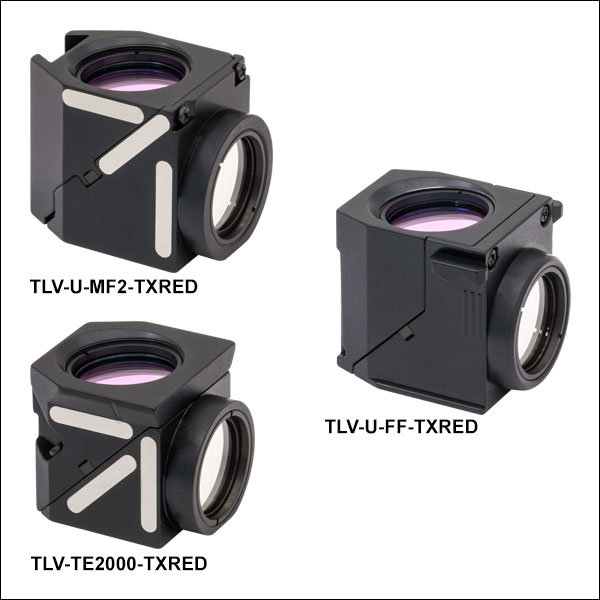
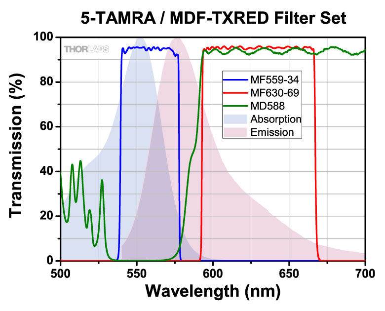
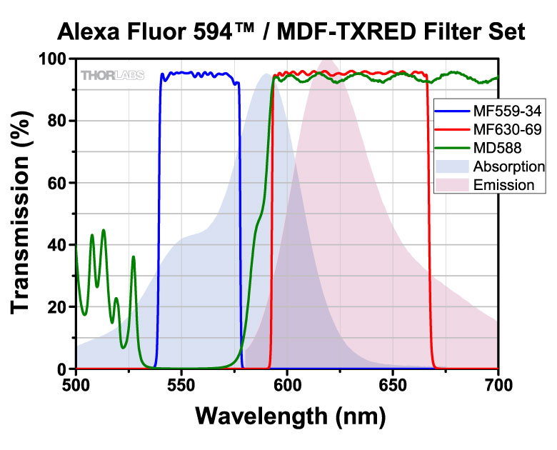
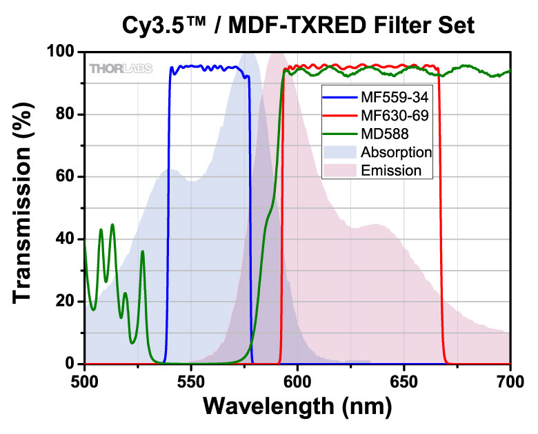
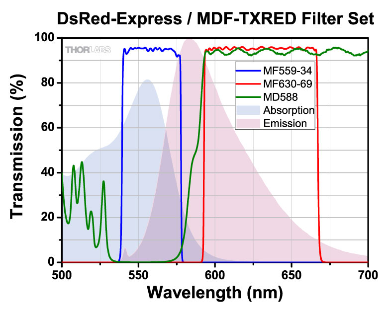
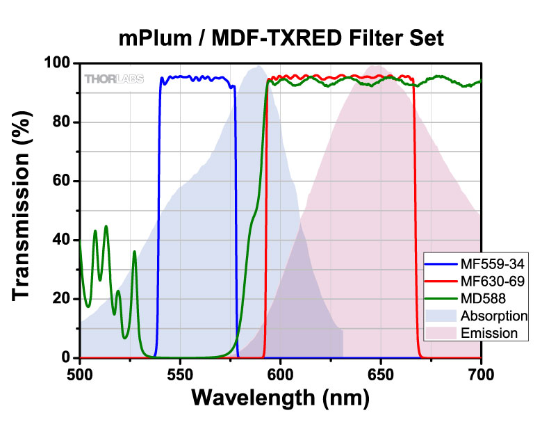
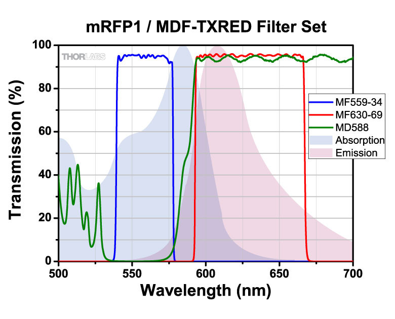
| Texas Red | 559 nm / 630 nm |
| mCherry | 562 nm / 641 nm |
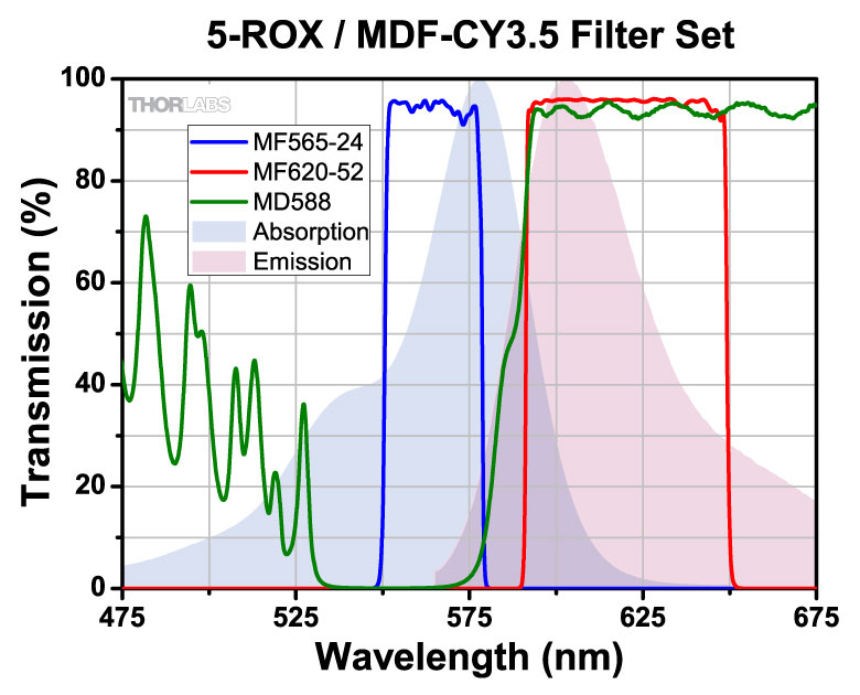
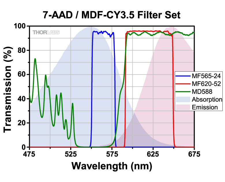
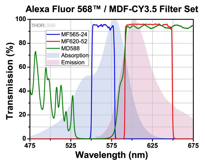
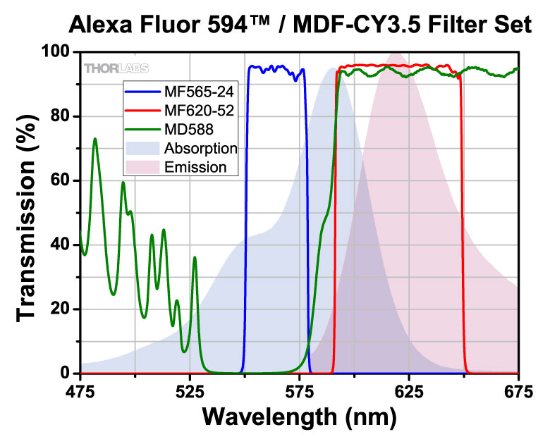
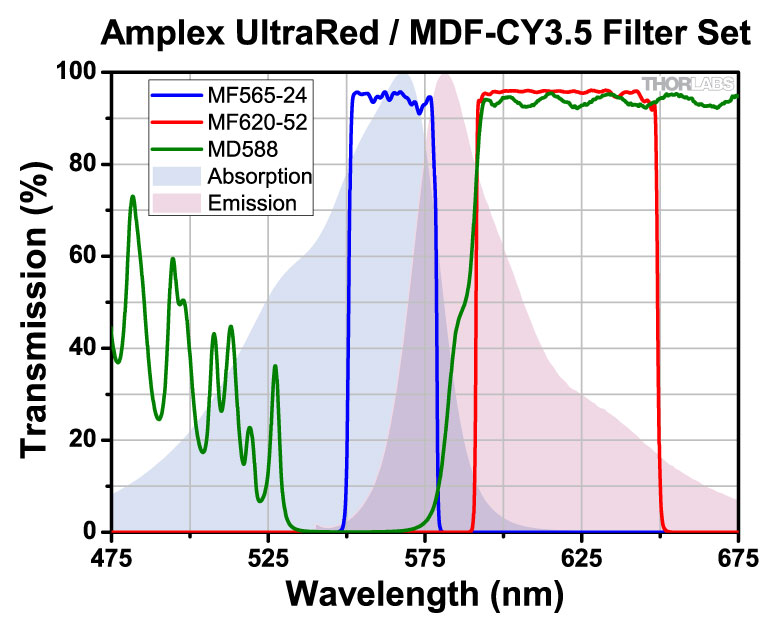
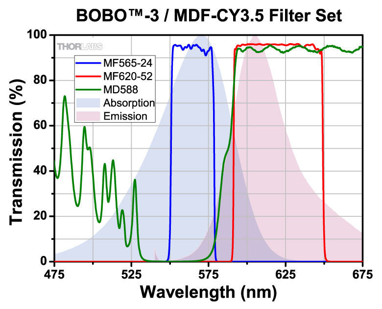
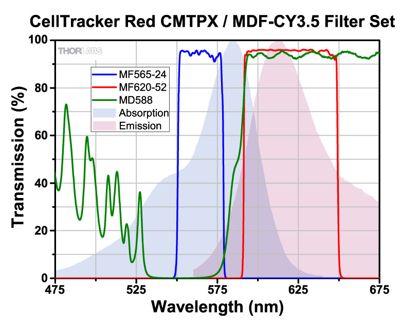
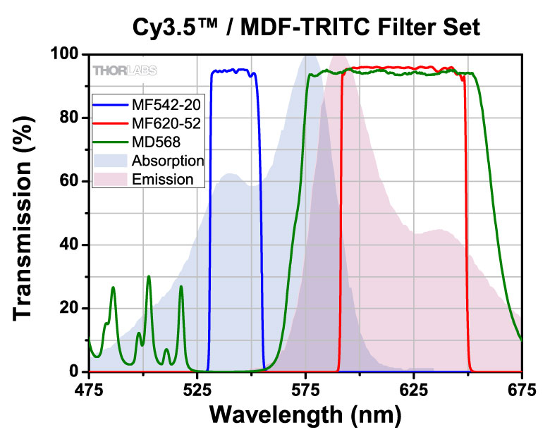
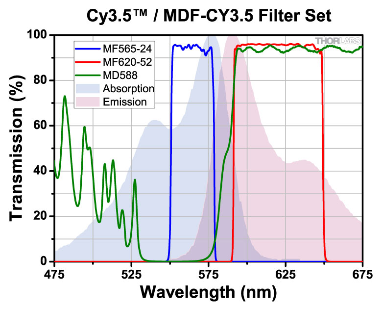
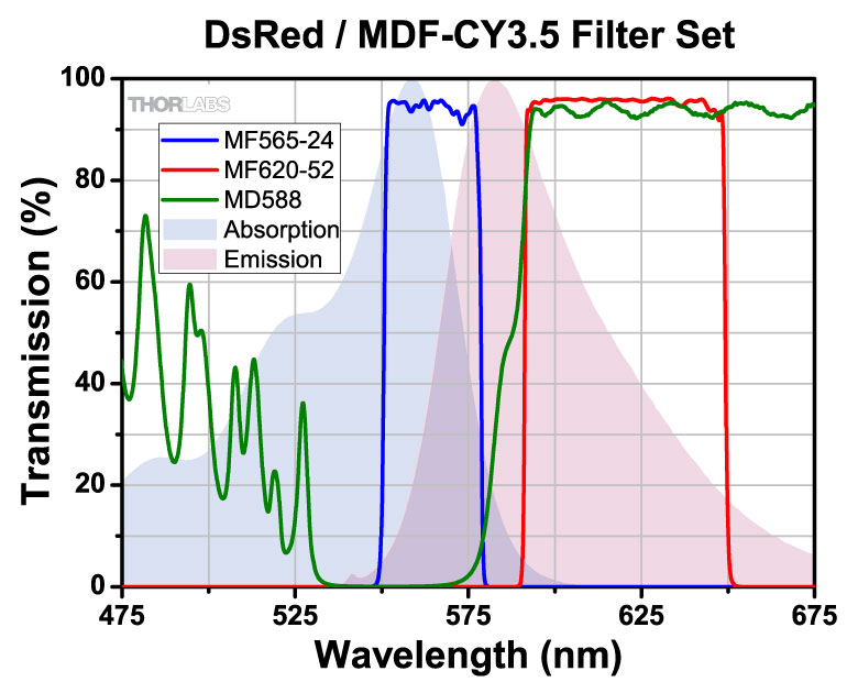
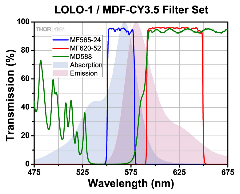
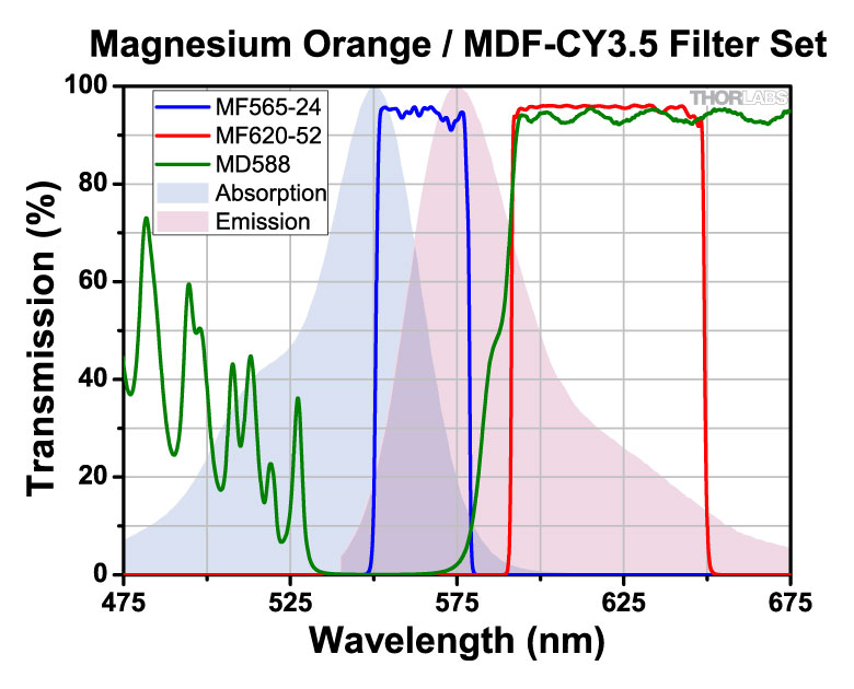
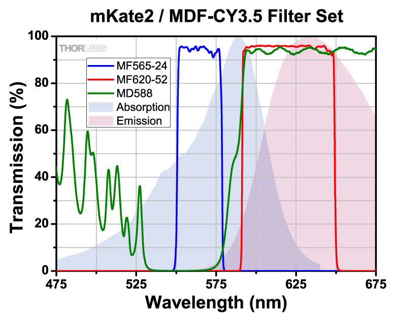
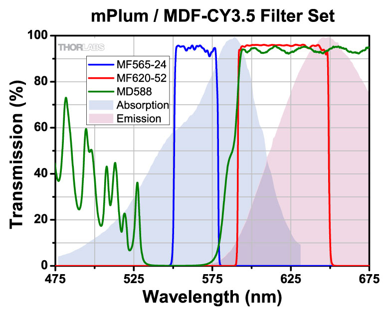
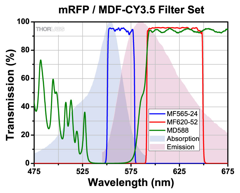
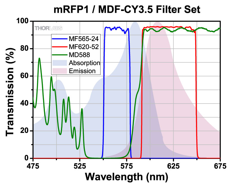
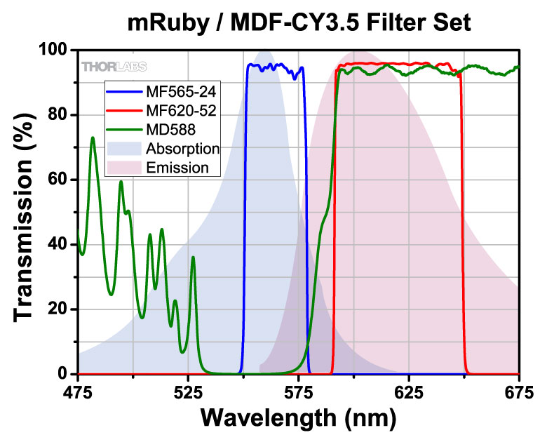
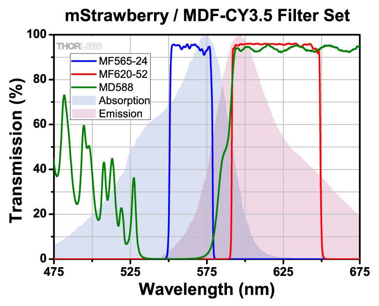
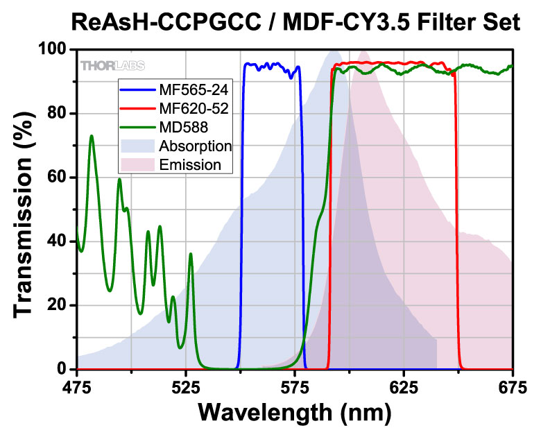
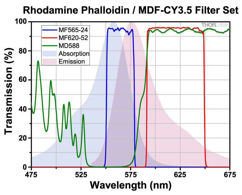
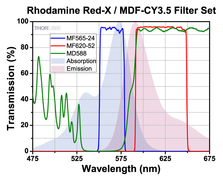
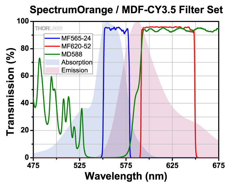
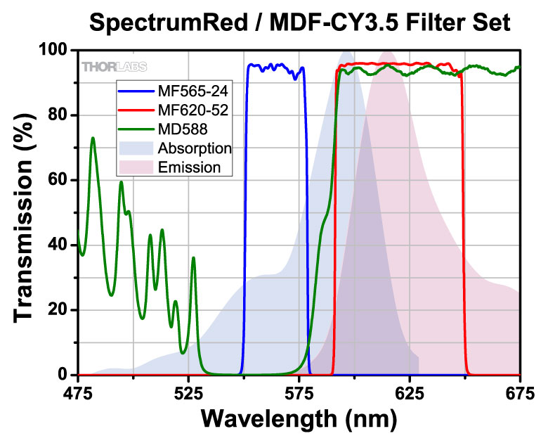
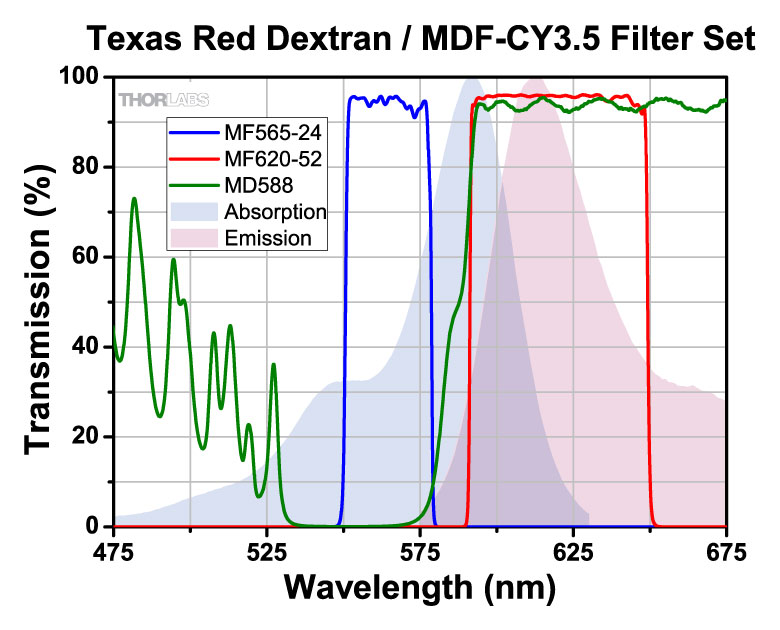
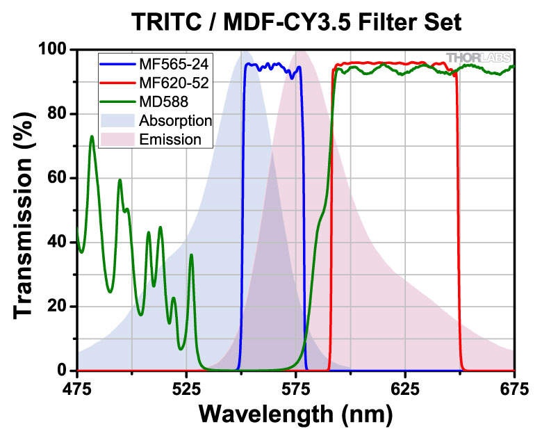
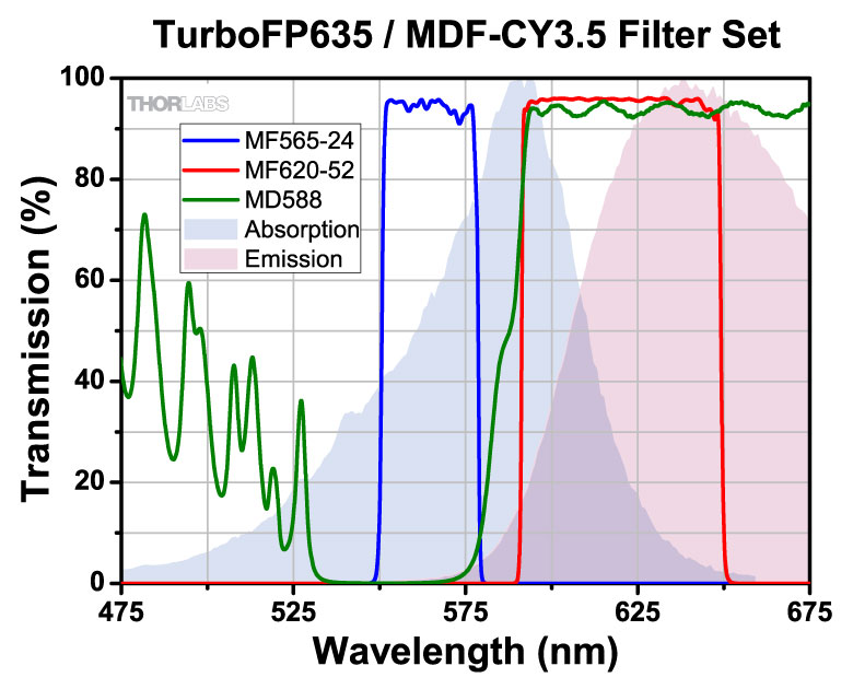
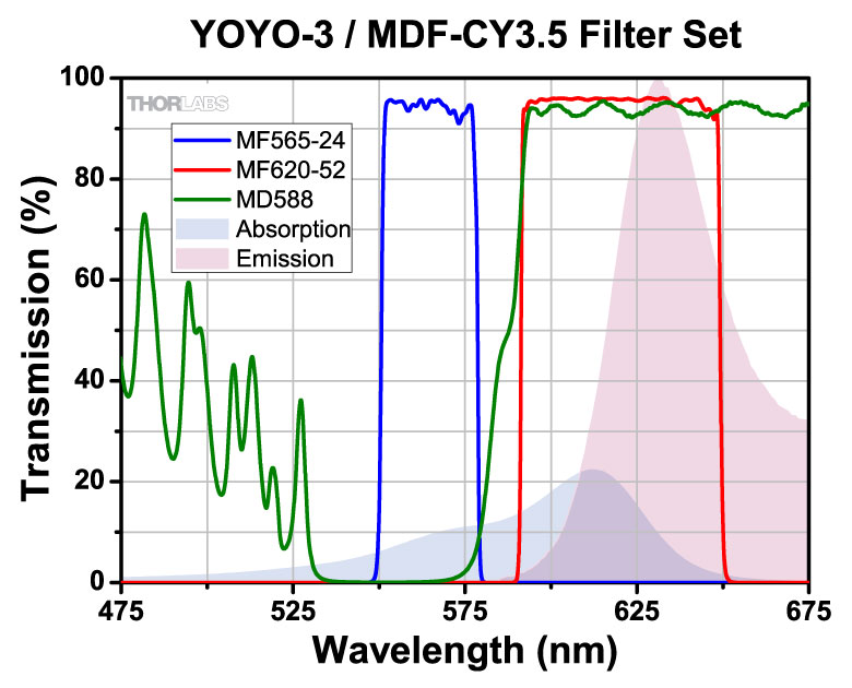
| Cyanine (Cy3.5) | 565 nm / 620 nm |
| mCherry | 578 nm / 641 nm |
Click to Enlarge
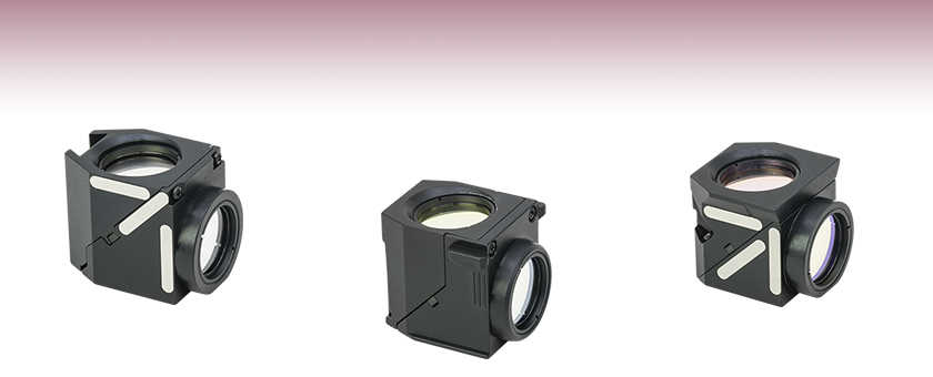
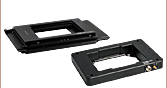
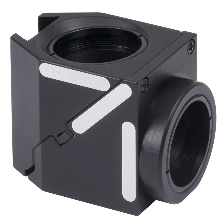
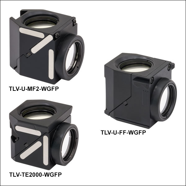
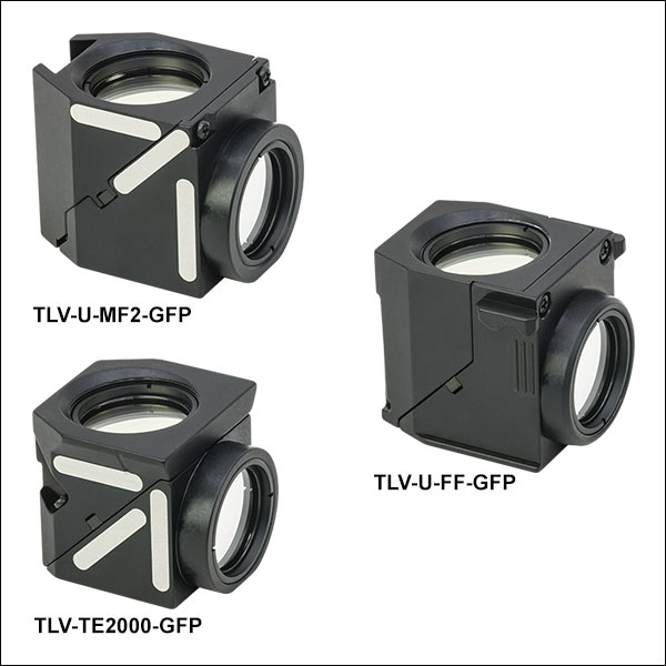
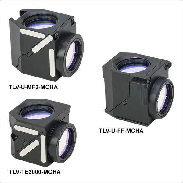
Thorlabs' filter cubes feature labels for identifying installed filters.
Features
- Drop-in Filter Cubes with Pre-Installed Fluorescence Filter Sets for Select Nikon and Olympus Microscopes (See Table Below)
- Filters Optimized for Common Fluorophores (See Table to the Right)
- Pre-Installed Filters Minimize Handling of Bare Optics
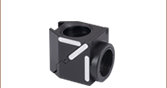
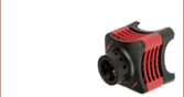
- Durable Aluminum Filter Cube Body
- Side Labels for Marking Installed Filters
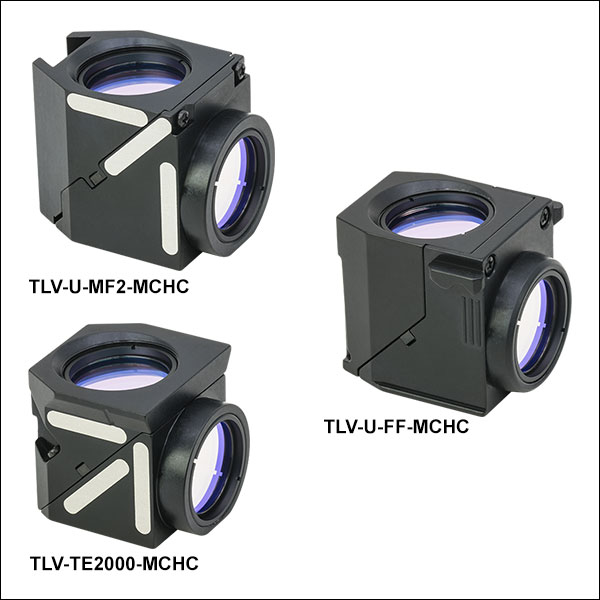
This page offers Thorlabs' microscope filter cubes with pre-installed fluorescence filter sets. Choose from 13 available imaging filter sets; each is optimized for a specific fluorophore (see table to the right for options). These filter sets can also be used with other fluorophores (see the Fluorophores tab for more information). Four filter cube body options are available for each filter set; they are compatible with select Olympus and Nikon fluorescence microscopes (see the table below for microscope compatibility).
Thorlabs also sells additional filters and imaging filter sets that are compatible with the cubes sold on this page. For users who already have imaging filter sets, we also provide empty microscope filter cube bodies. Pre-mounted filter cubes using any of our stock filters can be requested by contacting techsupport@thorlabs.com.
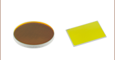
Filter Design
Our filters are manufactured to high-performance optical specifications and designed for durability. They are produced via multiple dielectric layers deposited on a high-precision, fused silica substrate. The substrate is ground and polished to ensure that the highest possible image quality is maintained. The resulting hard-coated optics consist of filter layers that are denser than those obtained from electron beam deposition techniques, and which reduce water absorption while greatly enhancing durability, stability, and performance of the filter. Each filter layer is monitored during growth to ensure minimal deviation from design specification thickness, ensuring overall high-quality filter performance.
Installation of Filters into the TLV-U-MF2 Cube
Microscopy Filter Cubes
These cubes feature a spring plate retention mechanism for the dichroic mirror that results in lower optic stress for improved imaging. Our design also offers an all-aluminum cube body, simplified optic mounting, and three labels for writing information about installed filters. Each cube is also engraved with the empty cube item number. Refer to the table below to view which filter cubes are compatible with which microscope.
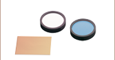
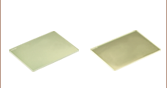
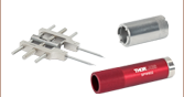
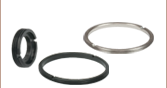
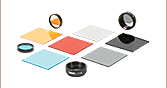
Although one filter set is pre-installed into each filter cube, users can easily swap the installed filters. The cubes are compatible with the following filters: one excitation filter (Ø25 mm, up to 5 mm thick), one emission filter (Ø25 mm, up to 3.5 mm thick), and one dichroic mirror (up to 25.2 mm x 36.0 mm x 1.1 mm). Optics can be mounted, aligned, and swapped out easily as illustrated in the video to the right. For detailed assembly instructions, please refer to the assembly manuals in the table below.
When these cubes are placed in a filter cube turret, it is important to balance the weight. To ensure longevity of a motorized filter cube turret and prevent unnecessary wear, please place filter cubes opposing each other to maintain balance.
| Microscope Compatibility of Filter Cubesa | |||
|---|---|---|---|
| Item # Prefix (Empty Cube Item #) | Microscope Manufacturer | Compatible Microscopes | Assembly Manual |
| TLV-U-MF2 | Olympus | AX, BX2, and IX2 Series | TLV-U-MF2 Manual |
| TLV-U-FF | Olympus | BX3 and IX3 Series | TLV-U-FF Manual |
| TLV-TE2000 | Nikon | TE2000, 50i, 55i, 80i, 90i, Eclipse Ti, and Epi-Fluor Illuminator Scopes | TLV-TE2000 Manual |
| Specification | Excitation Filters | Emission Filters | Dichroic Filters | |||
|---|---|---|---|---|---|---|
| MDF-GFP2, MDF-TOM, MDF-MCHC, & MDF-MCHA Sets |
All Other Excitation Filters |
MDF-GFP2, MDF-TOM, MDF-MCHC, & MDF-MCHA Sets |
All Other Excitation Filters |
Dichroics in MDF-GFP2, MDF-MCHA, MDF-MCHC, & MDF-TOM Sets |
All Other Dichroics | |
| Size | Ø25 +0.0/-0.1 mm | Ø25 ± 0.1 mm | Ø25 +0.0/-0.1 mm | Ø25 ± 0.1 mm | 25.2 mm x 35.6 mm | 25.0 mm x 36.0 mm |
| Clear Aperture | >Ø21 mm | >Ø22 mm | >Ø21 mm | 80% of Area | >(22.5 mm x 32.4 mm) | |
| Angle of Incidence | 0° ± 5° | 45° ± 1.5° | ||||
| Thickness | 5.0 ± 0.1 mm | 3.5 ± 0.1 mm | 1.05 ± 0.05 mm | 1.0 ± 0.1 mm | ||
| Surface Quality | 60-40 Scratch-Dig | |||||
| Substrate | Fused Silica | |||||
| Filter Set Item # | Fluorophore | Filter Type | Center Wavelength | FWHM | Reflection Band | Transmission Band | AR Coatinga | Transmission Datab |
|---|---|---|---|---|---|---|---|---|
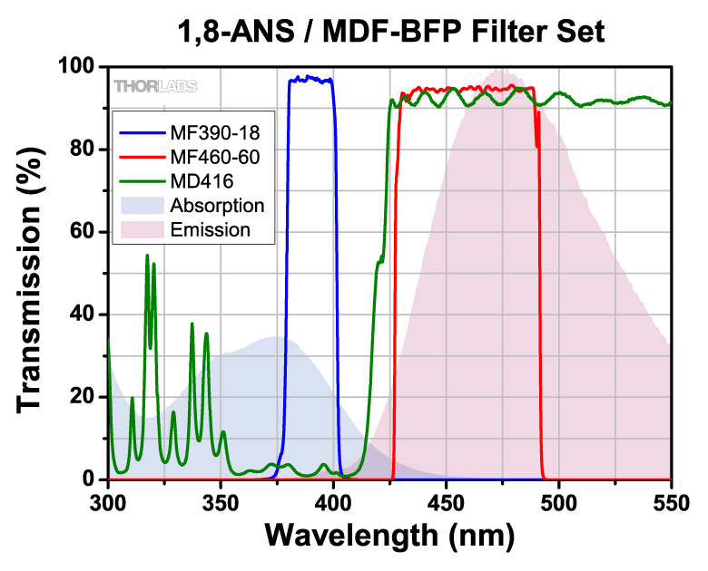
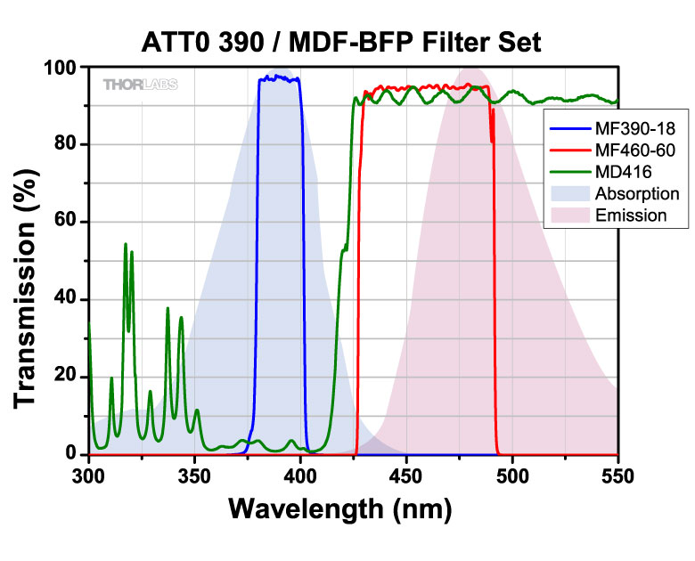
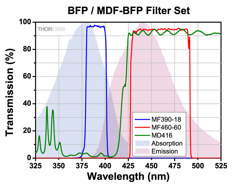
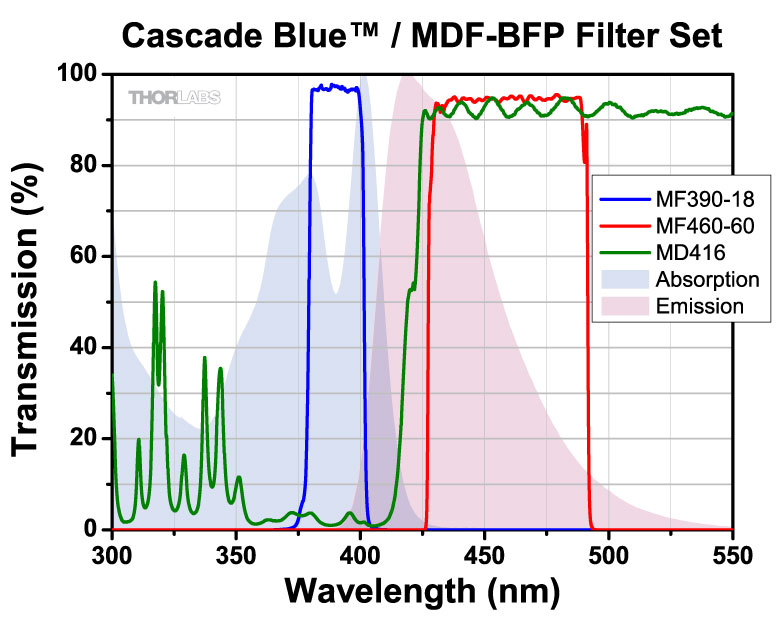
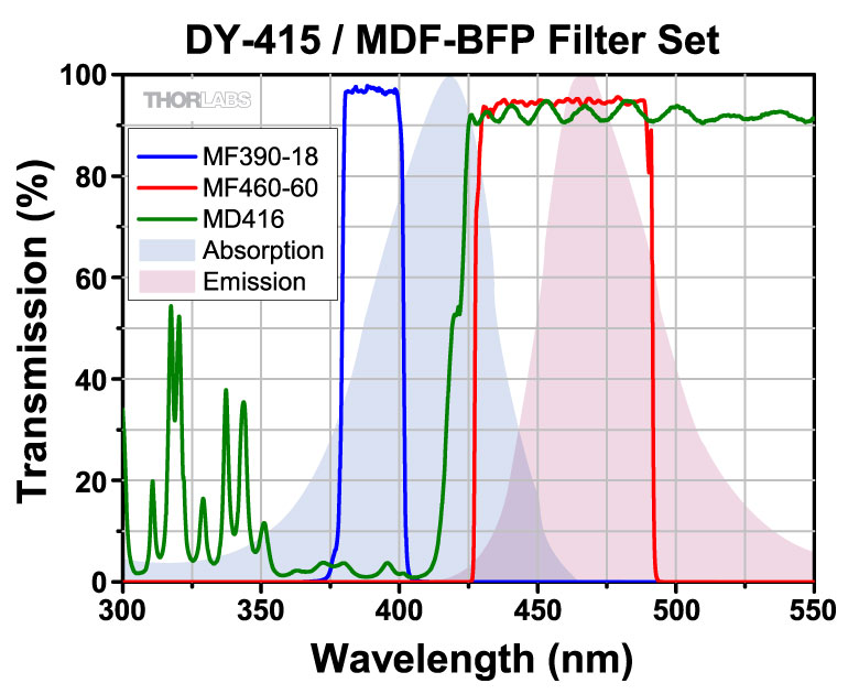
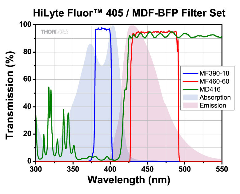
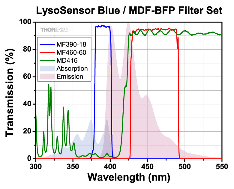
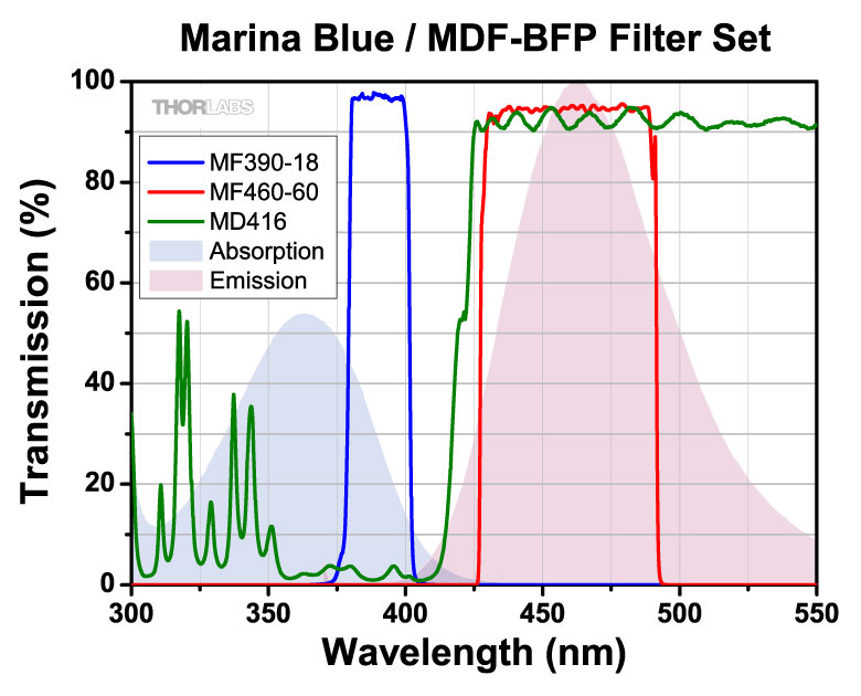
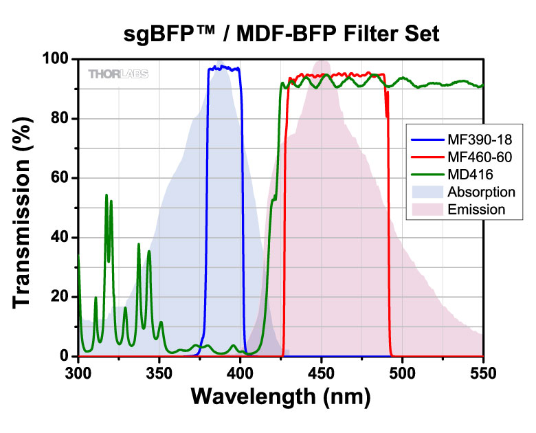
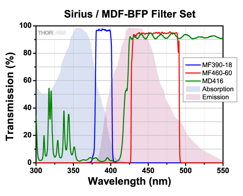
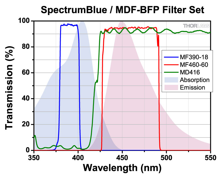
| MDF-BFP | BFP | Excitation | 390 nm | 18 nm | - | - | - | |
| Emission | 460 nm | 60 nm | - | - | - | |||
| Dichroic | - | - | 360 - 407 nm | 425 - 575 nm | Rabs < 2% from 400 to 800 nm |
|||
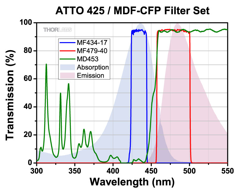
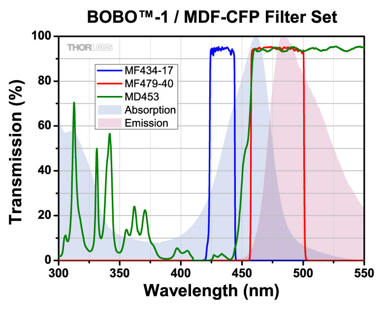
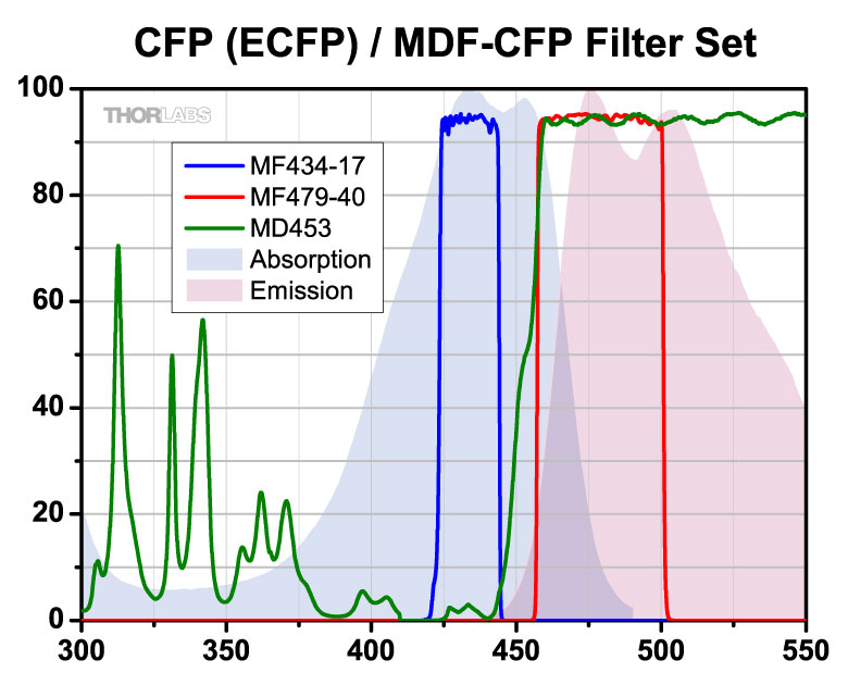
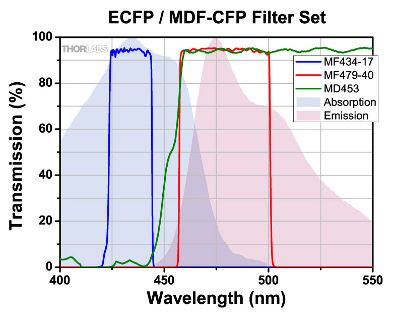
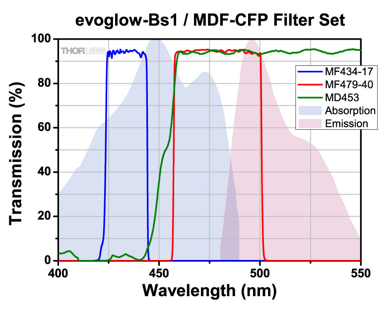
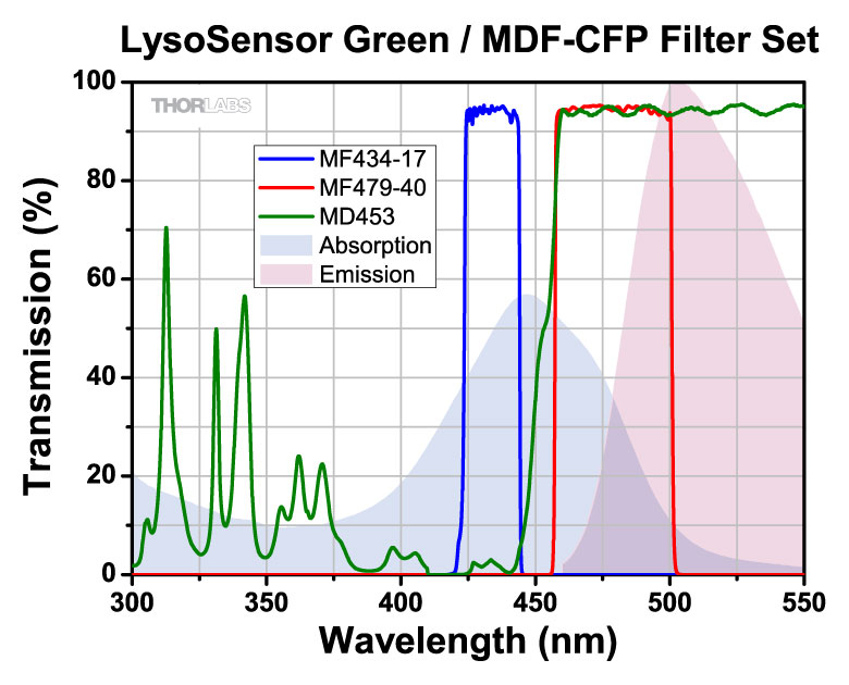
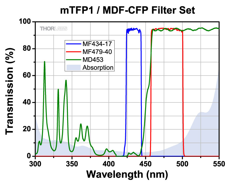
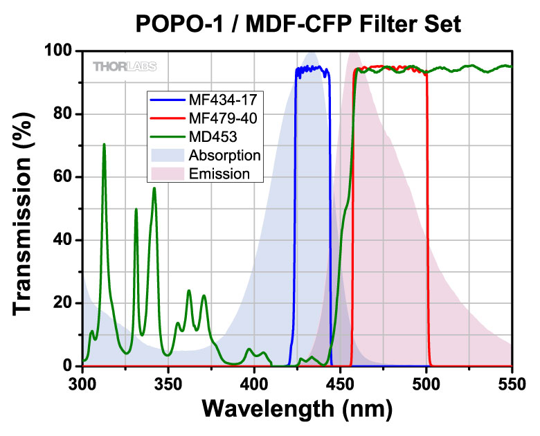
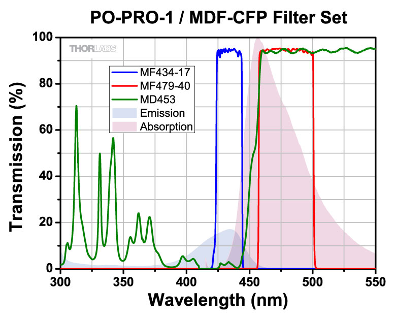
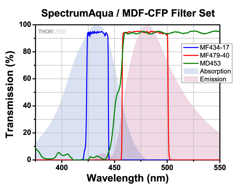
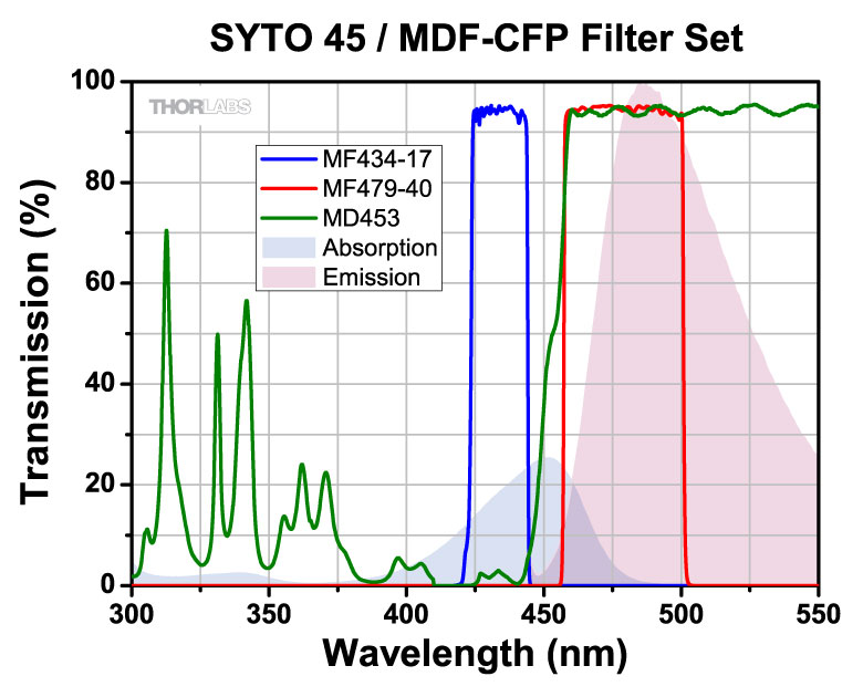
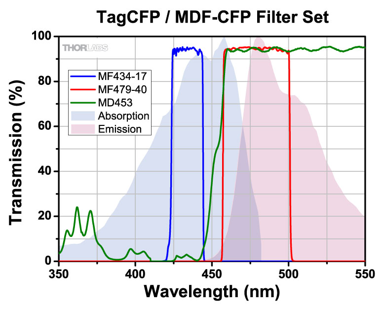
| MDF-CFP | CFP | Excitation | 434 nm | 17 nm | - | - | - | |
| Emission | 479 nm | 40 nm | - | - | - | |||
| Dichroic | - | - | 423 - 445 nm | 460 - 610 nm | Rabs < 2% from 400 to 800 nm |
|||
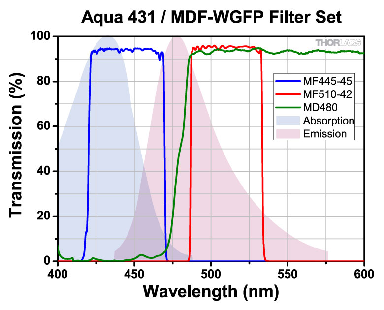
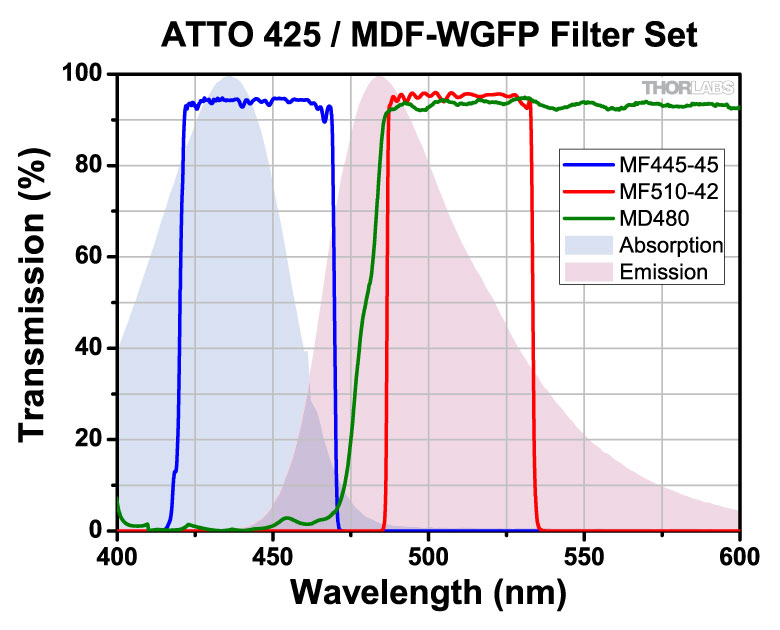
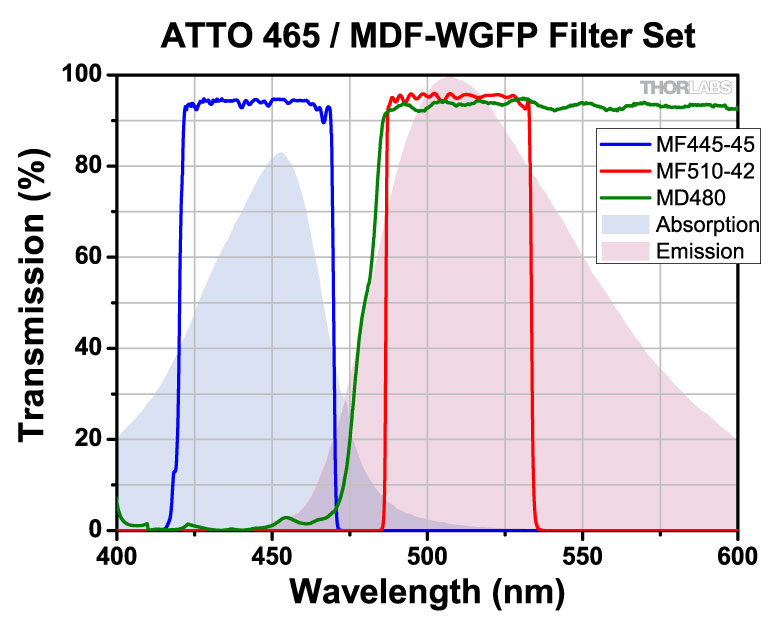
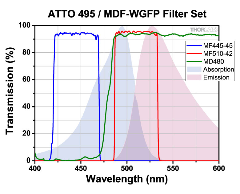
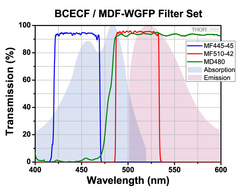
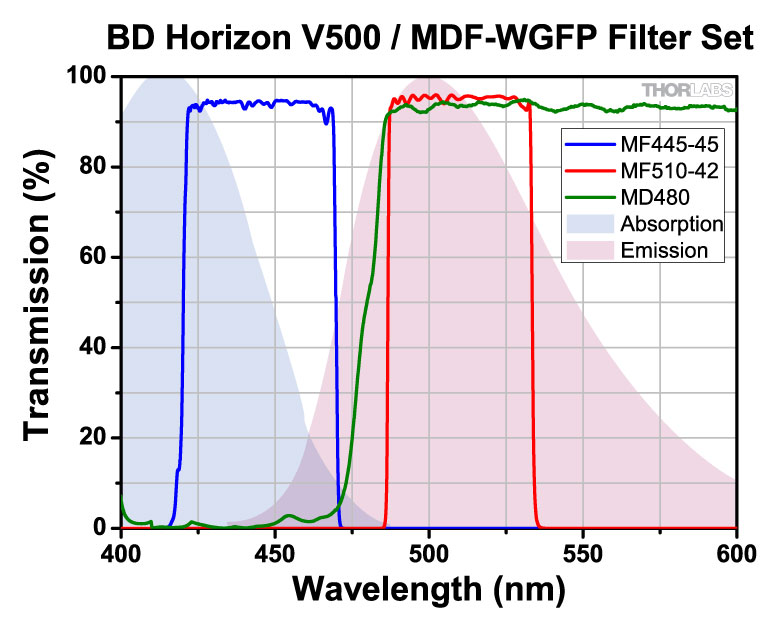
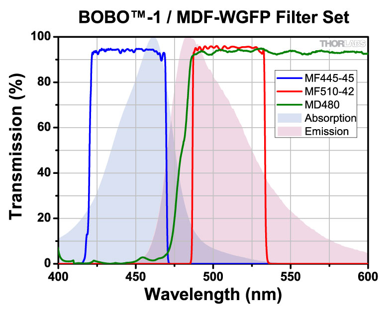
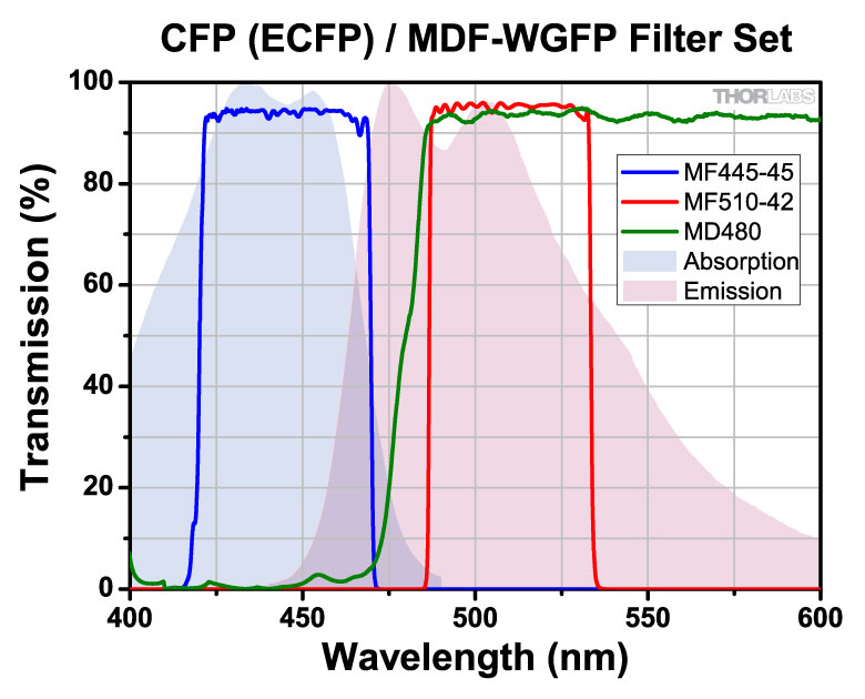
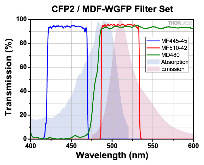
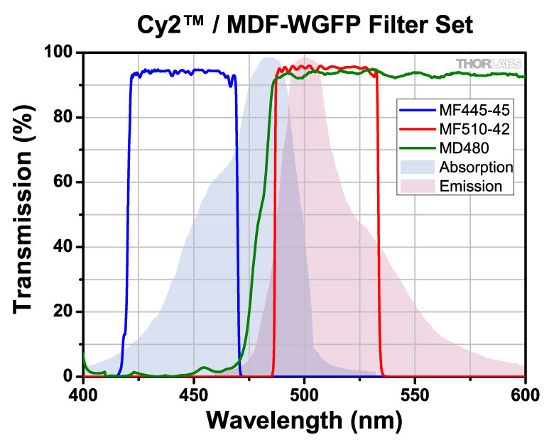
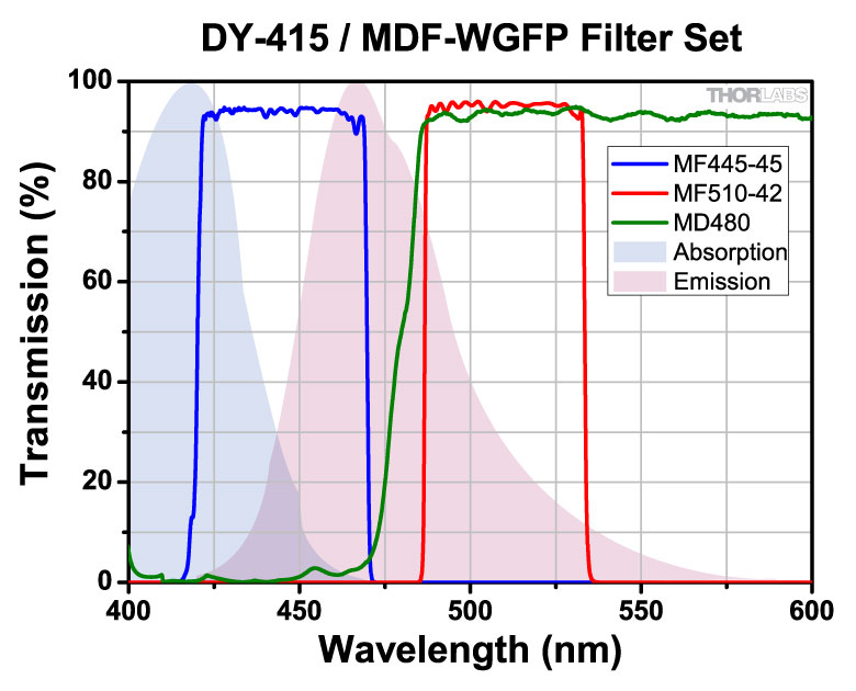
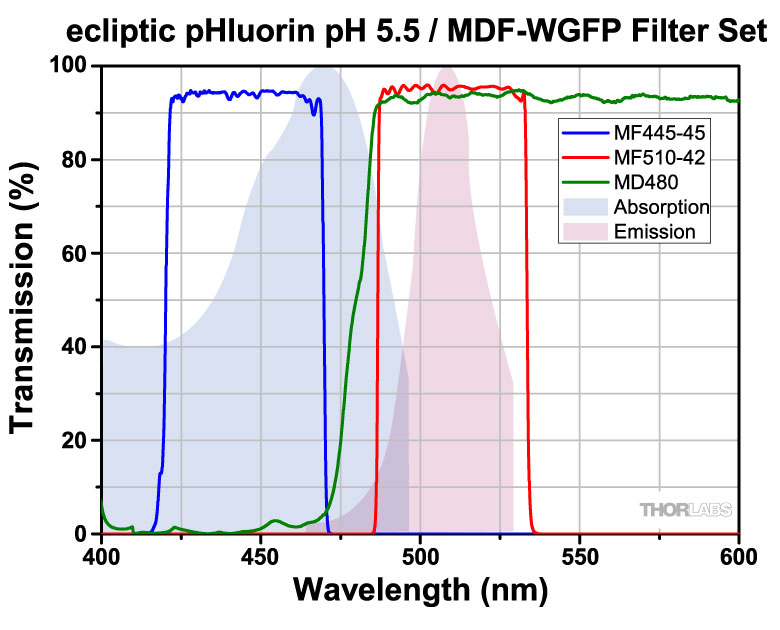
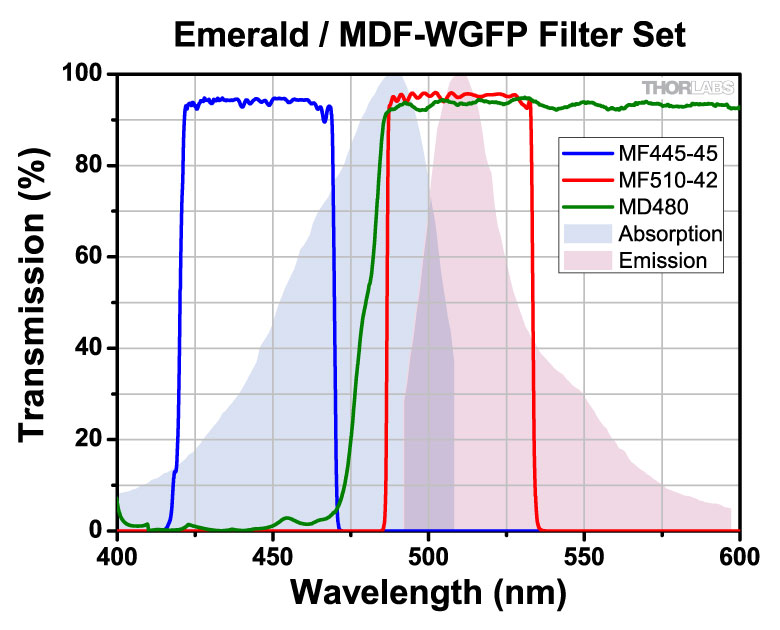
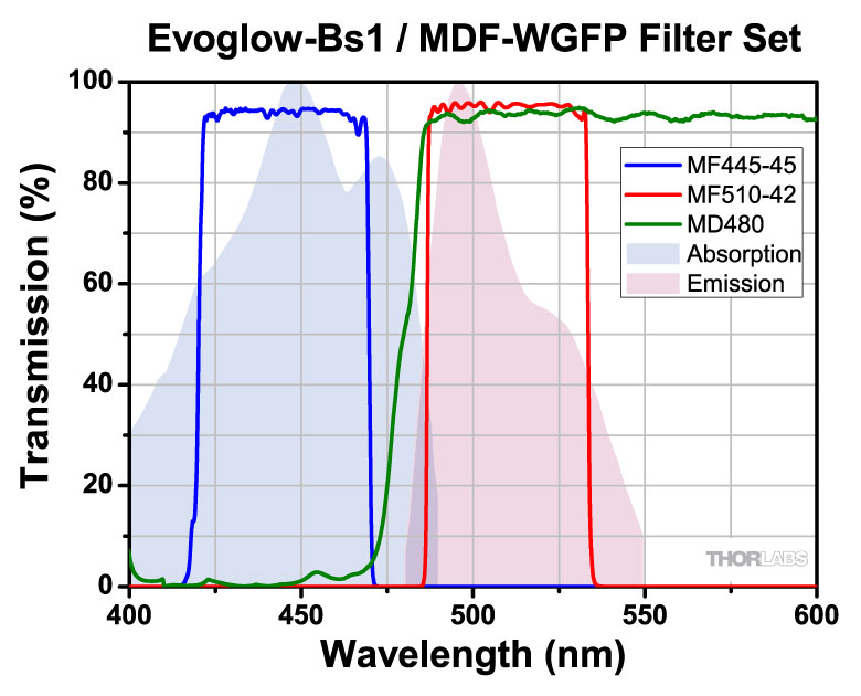
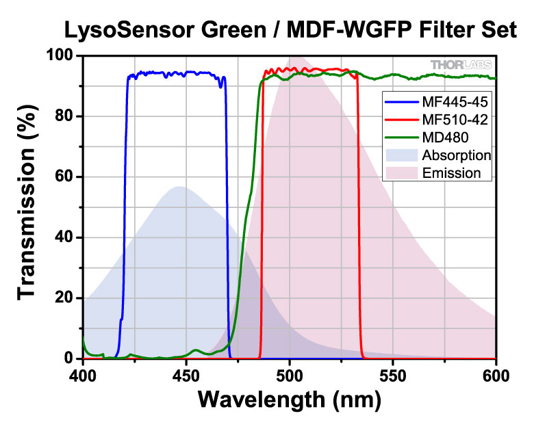
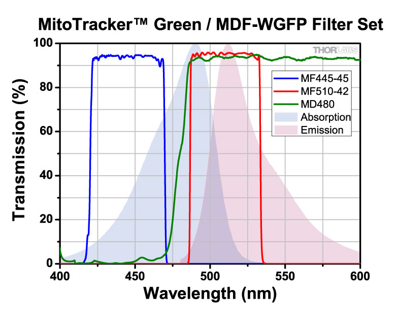
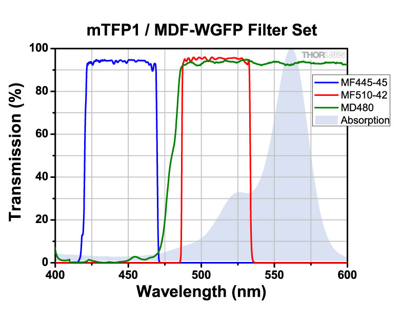
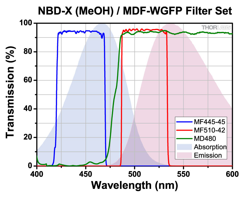
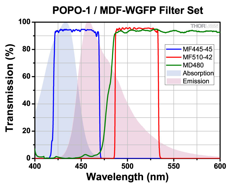
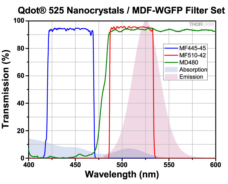
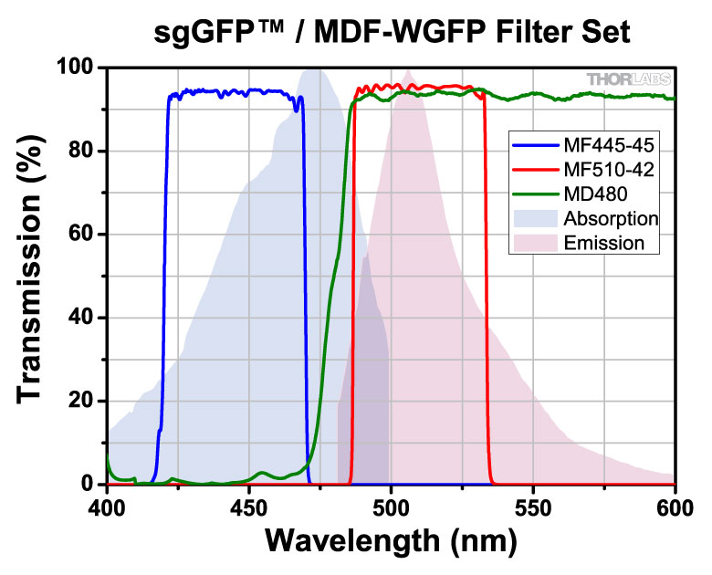
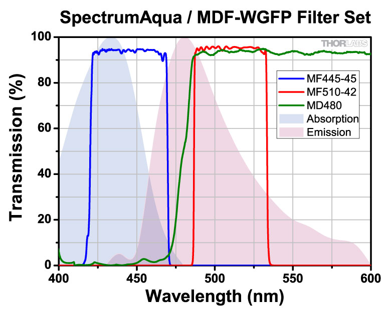
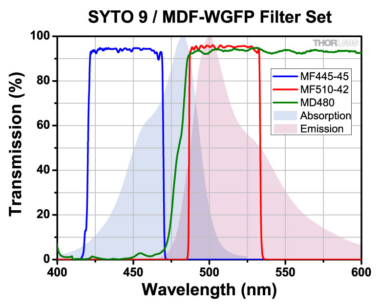
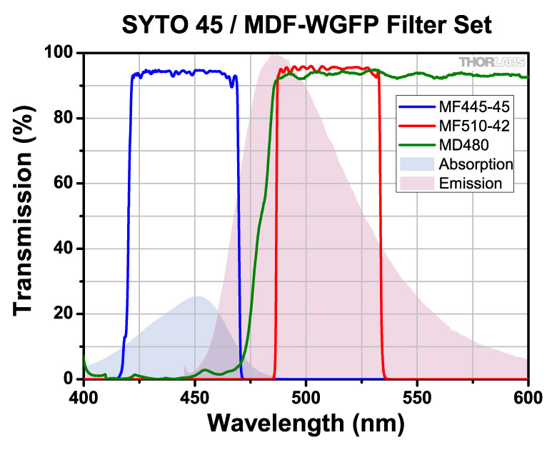
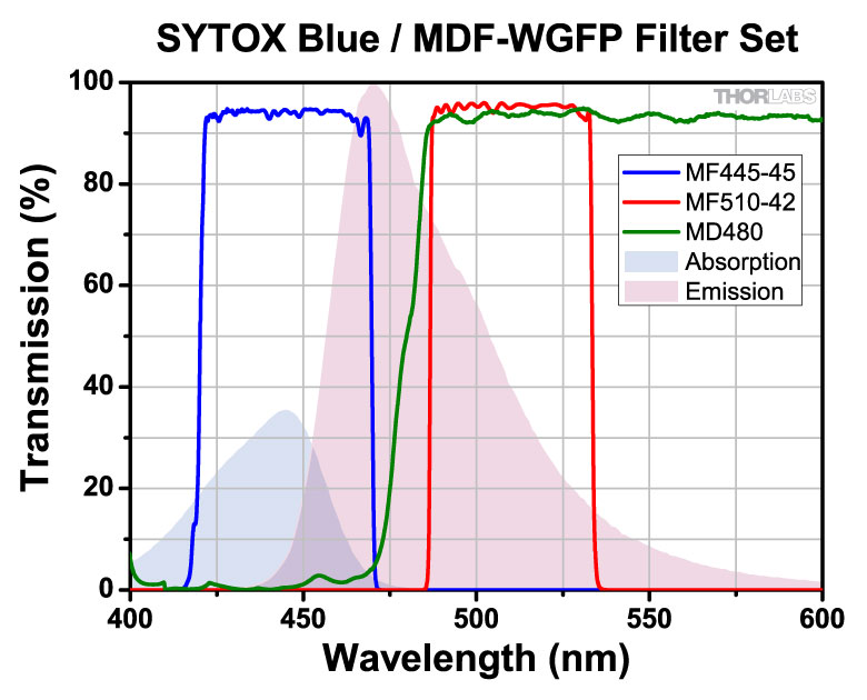
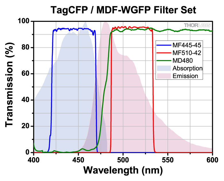
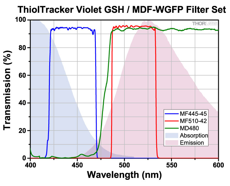
| MDF-WGFP | Wild Type GFP | Excitation | 445 nm | 45 nm | - | - | - | |
| Emission | 510 nm | 42 nm | - | - | - | |||
| Dichroic | - | - | 415 - 470 nm | 490 - 720 nm | Rabs < 2% from 400 to 800 nm |
|||
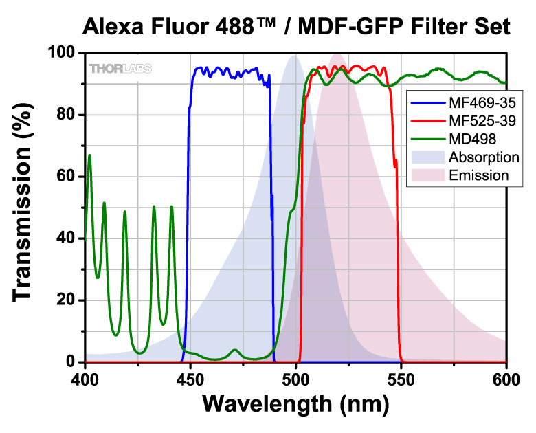
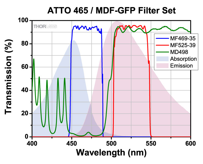
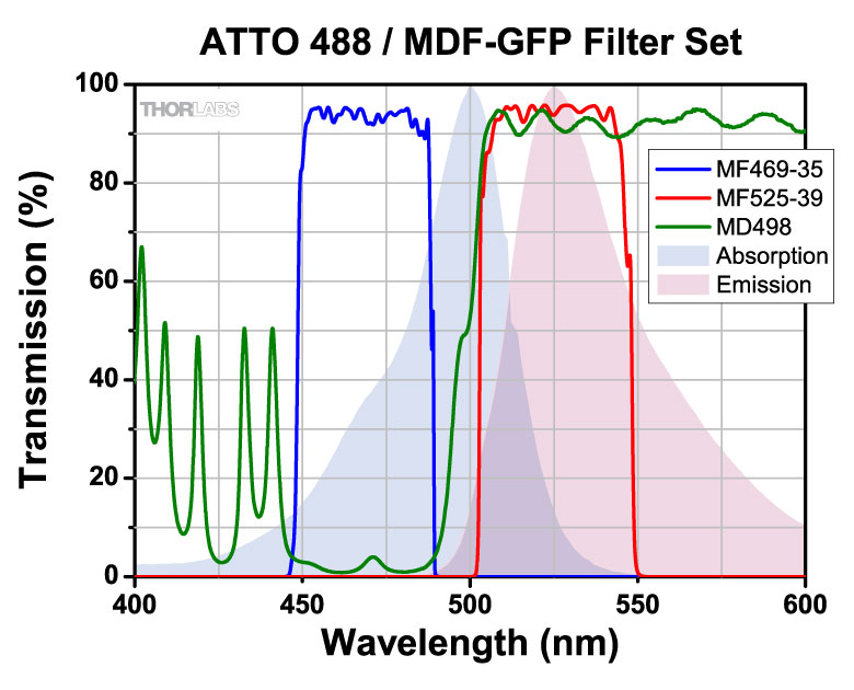
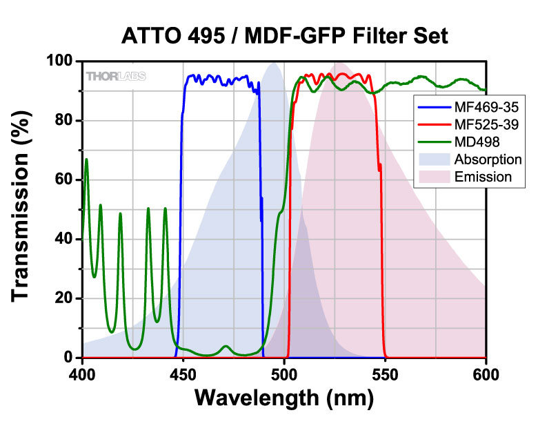
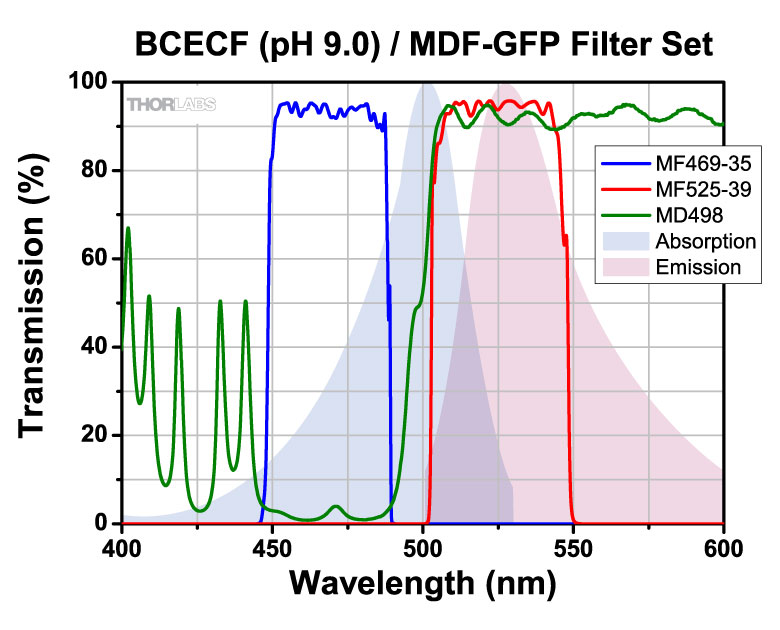
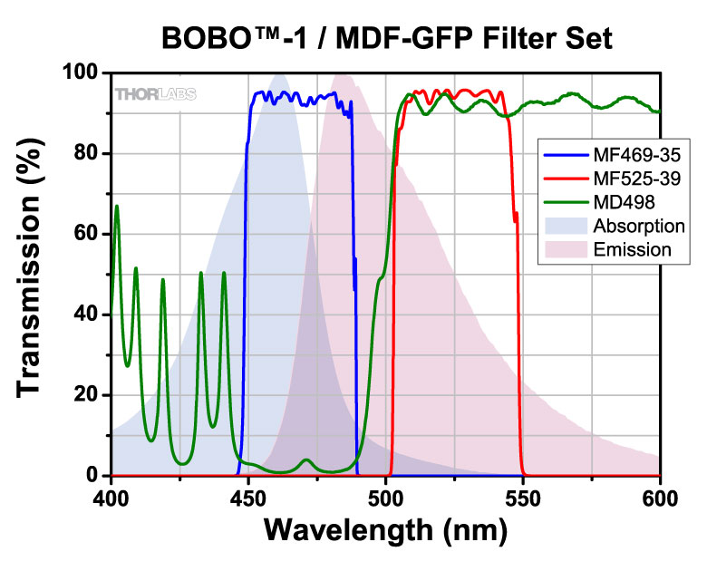
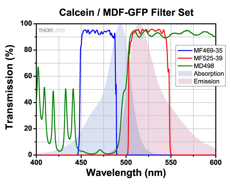
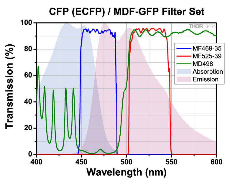
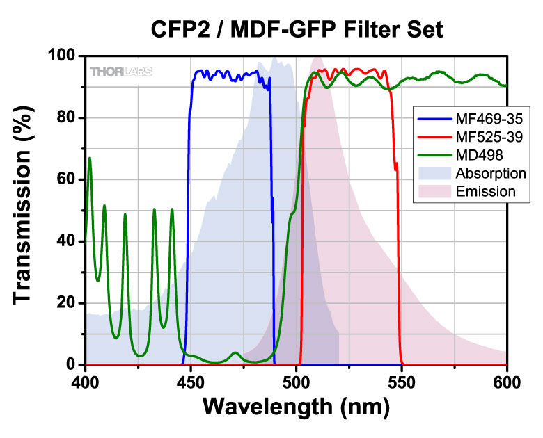
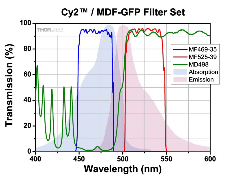
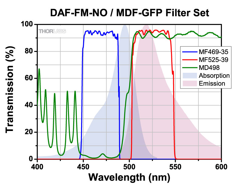
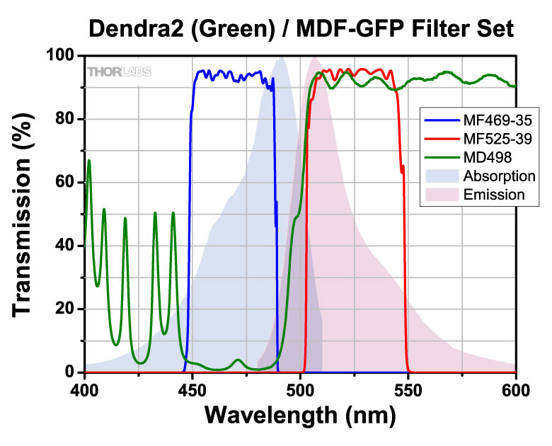
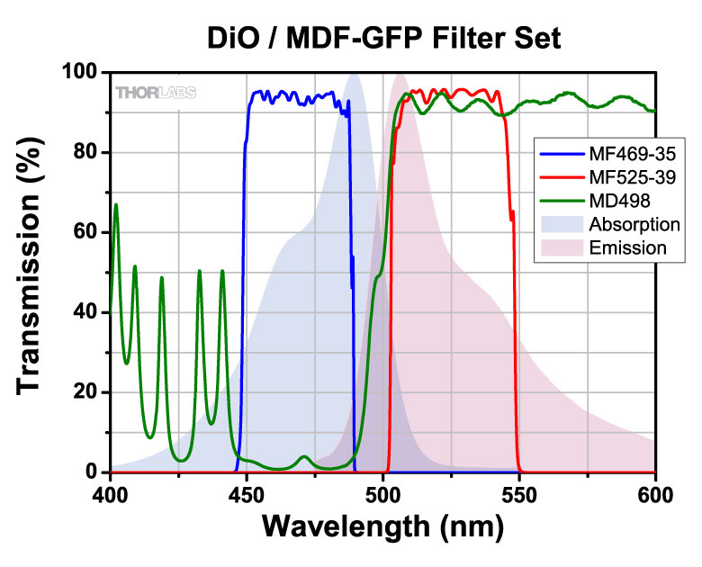
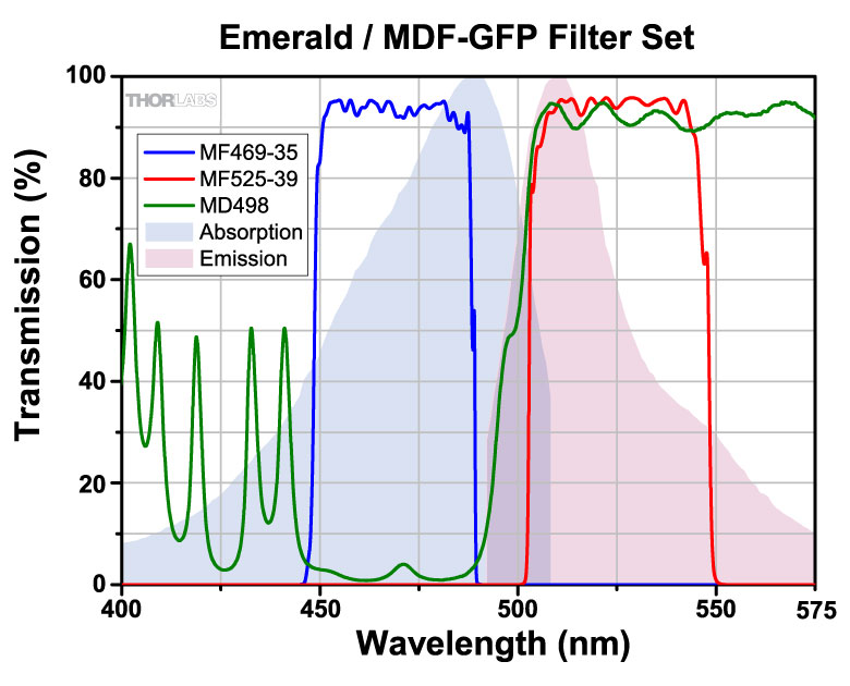
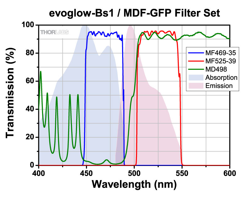
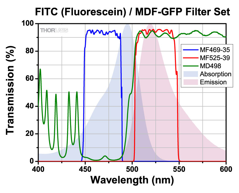
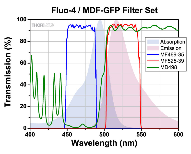
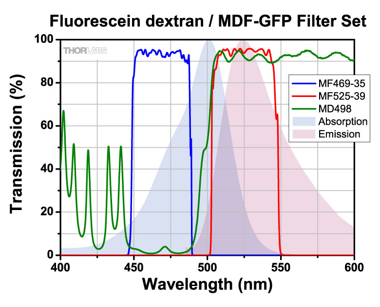
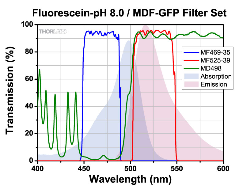
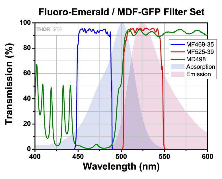
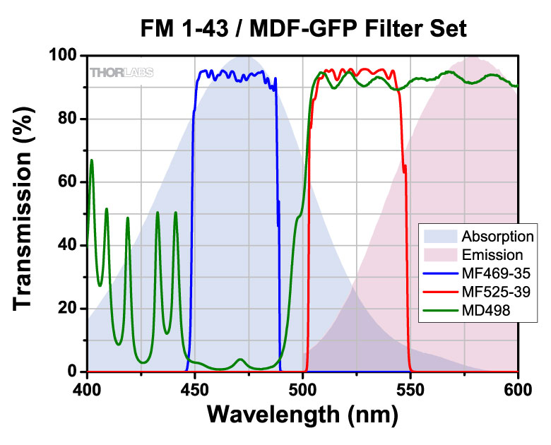
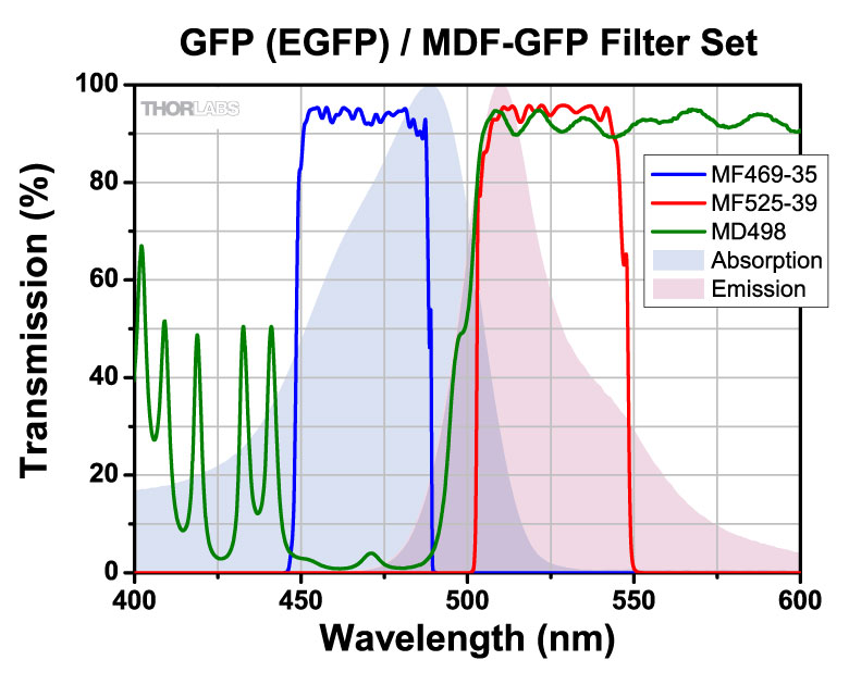
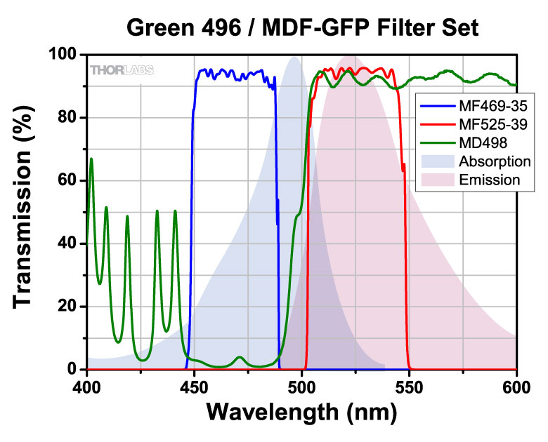
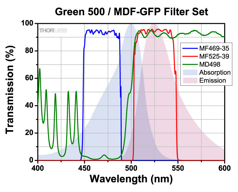
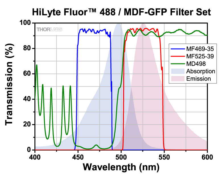
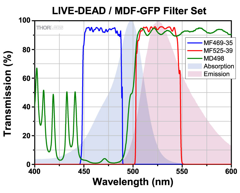
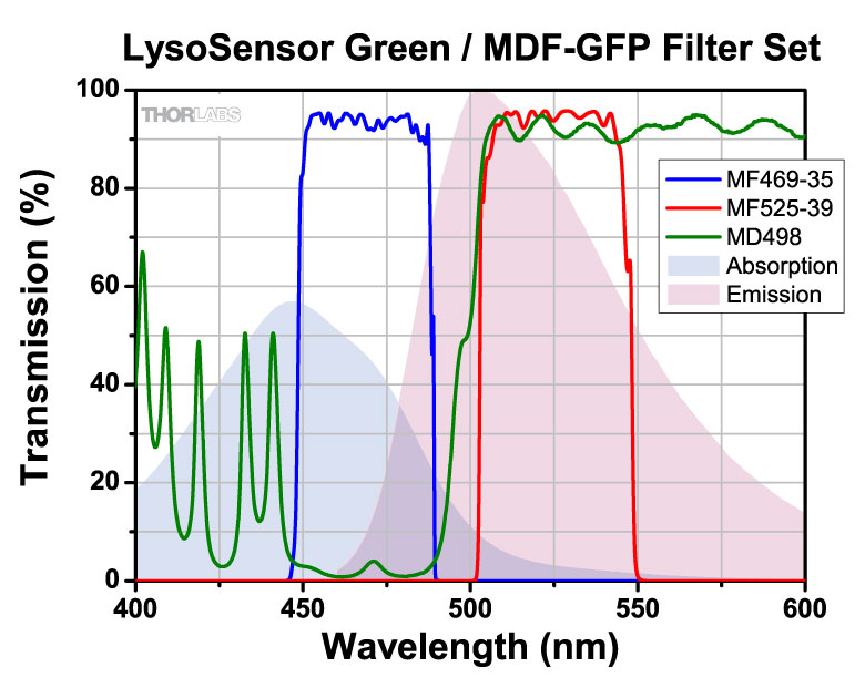
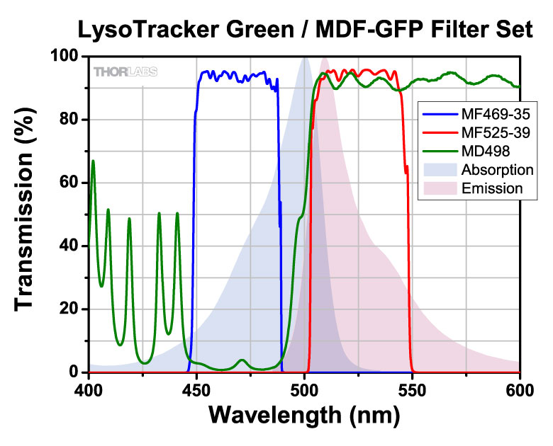
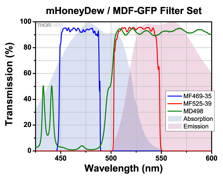
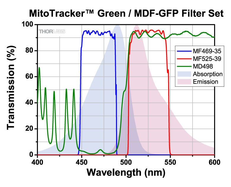
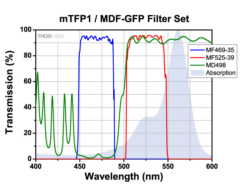
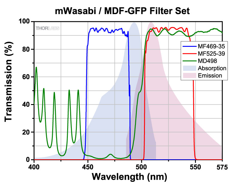
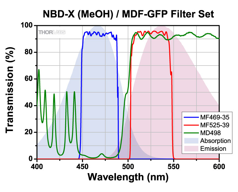
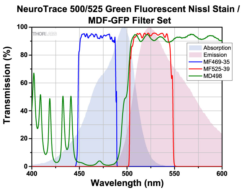
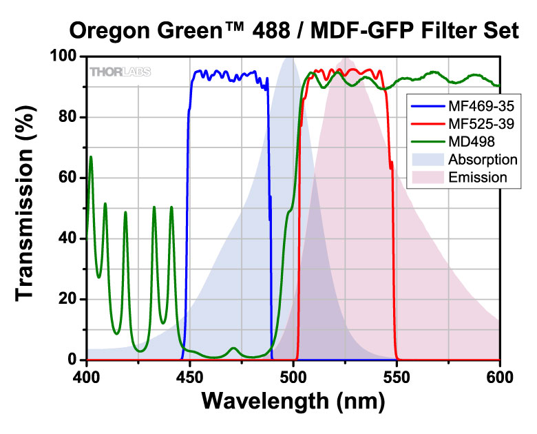
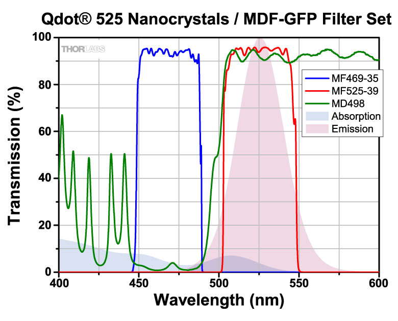
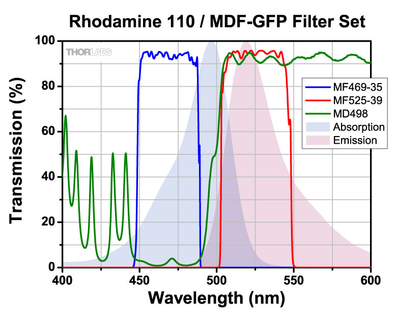
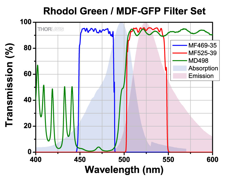
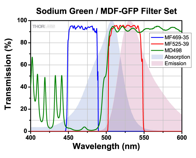
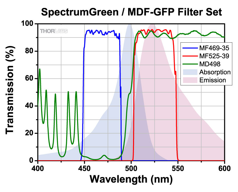
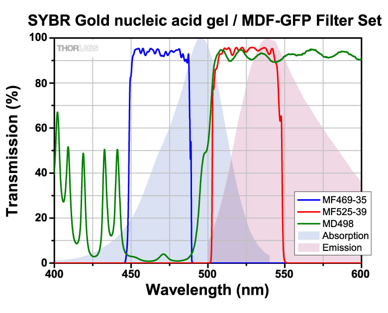
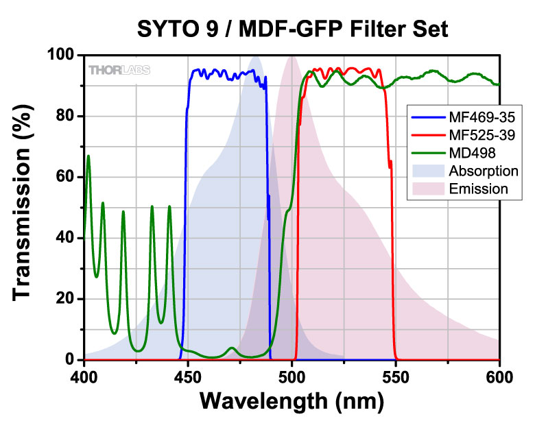
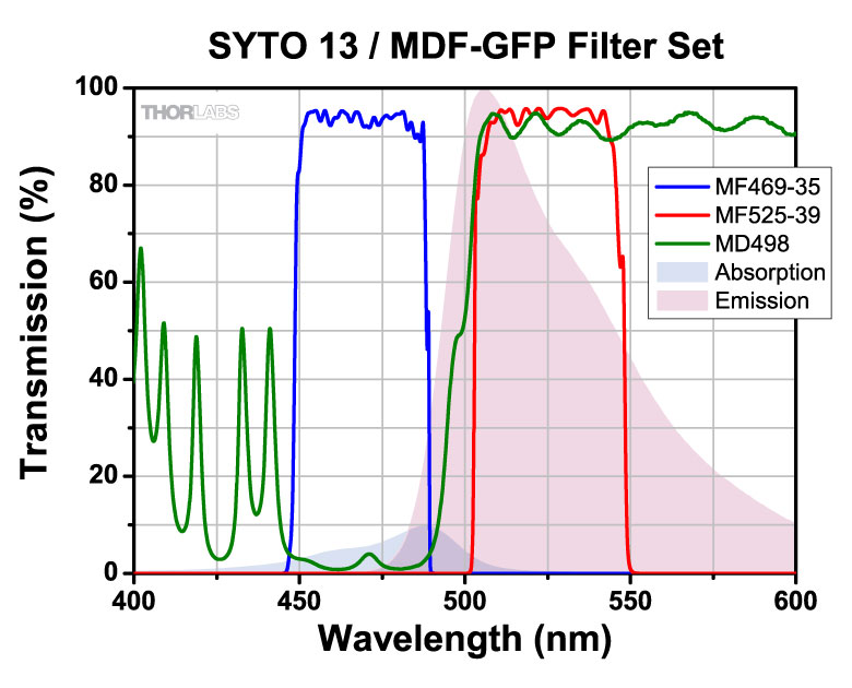
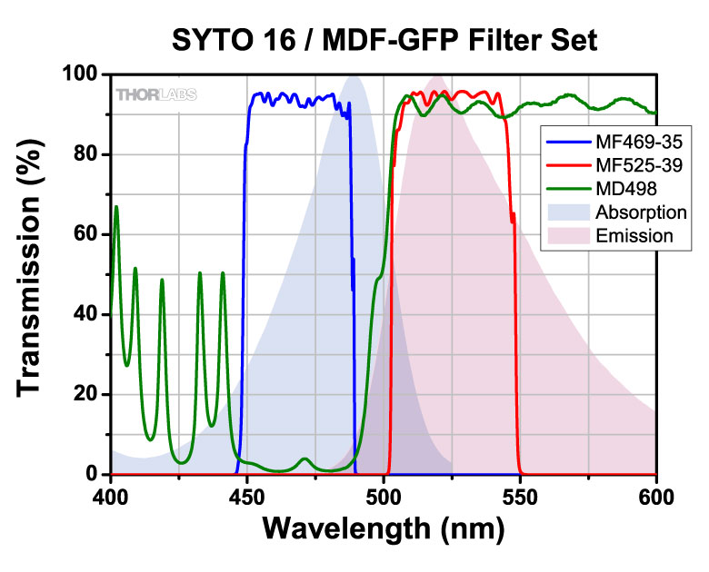
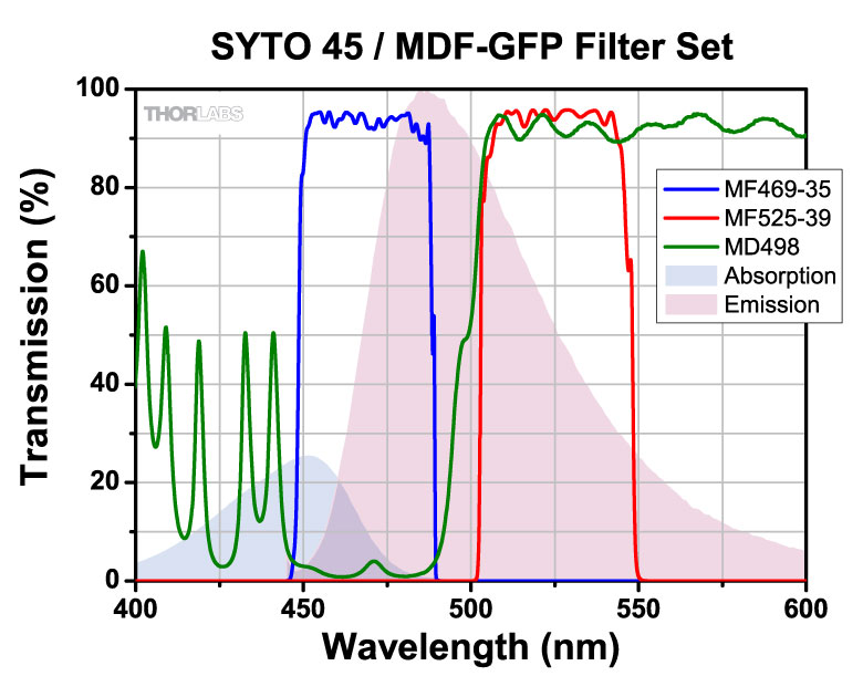
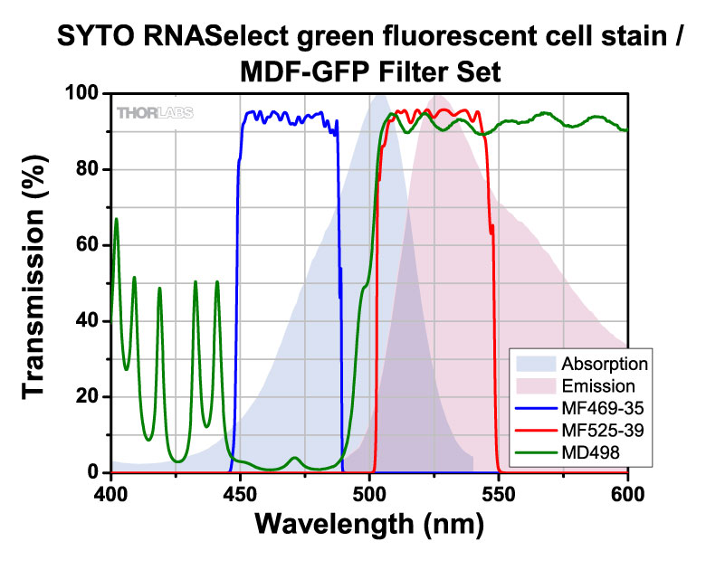
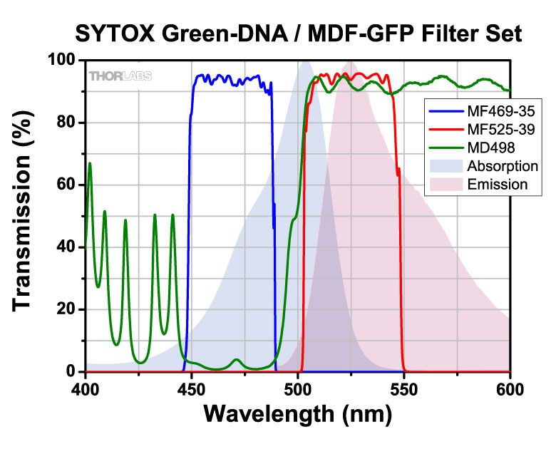
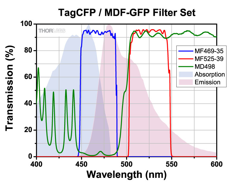
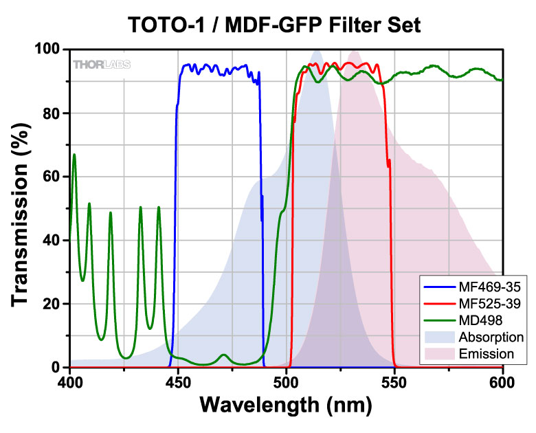
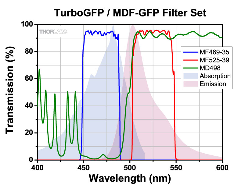
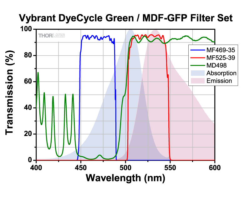
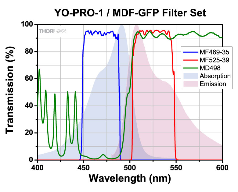
| MDF-GFP | GFP | Excitation | 469 nm | 35 nm | - | - | - | |
| Emission | 525 nm | 39 nm | - | - | - | |||
| Dichroic | - | - | 452 - 490 nm | 505 - 800 nm | Rabs < 2% from 400 to 800 nm |
|||
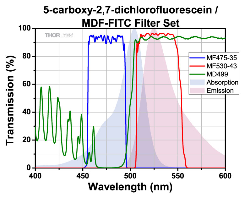
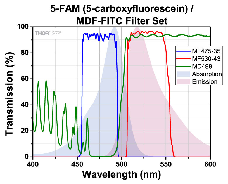
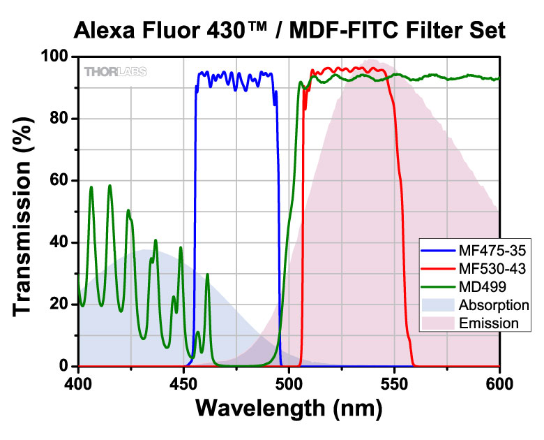
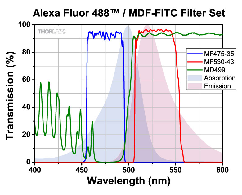
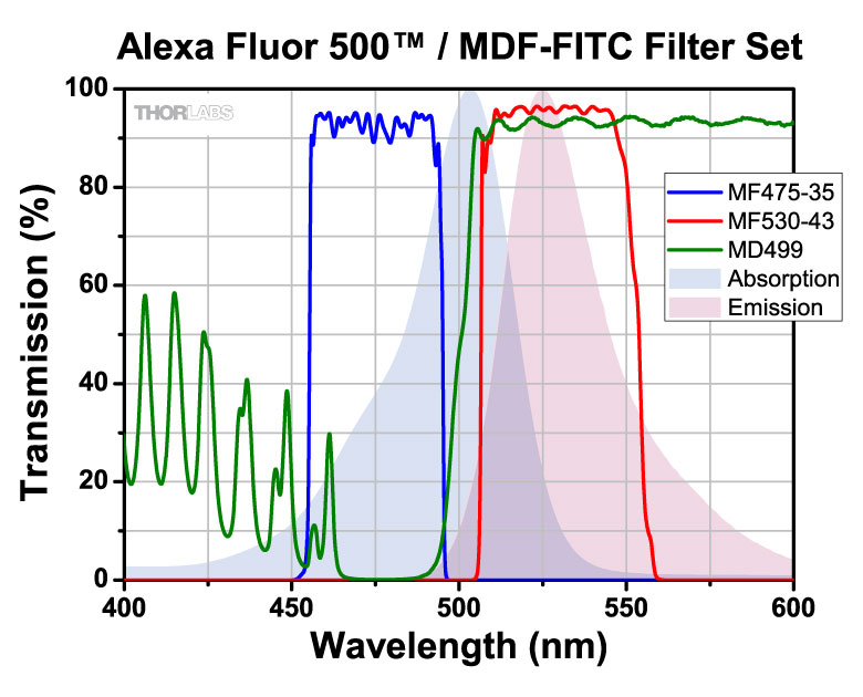
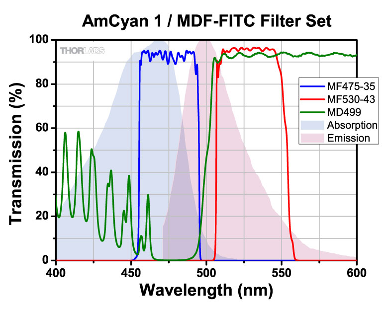
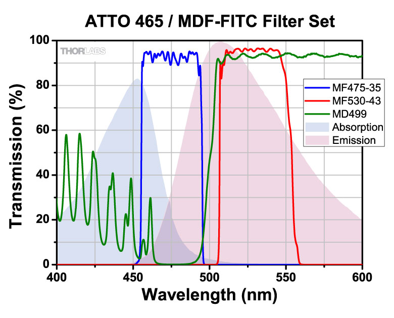
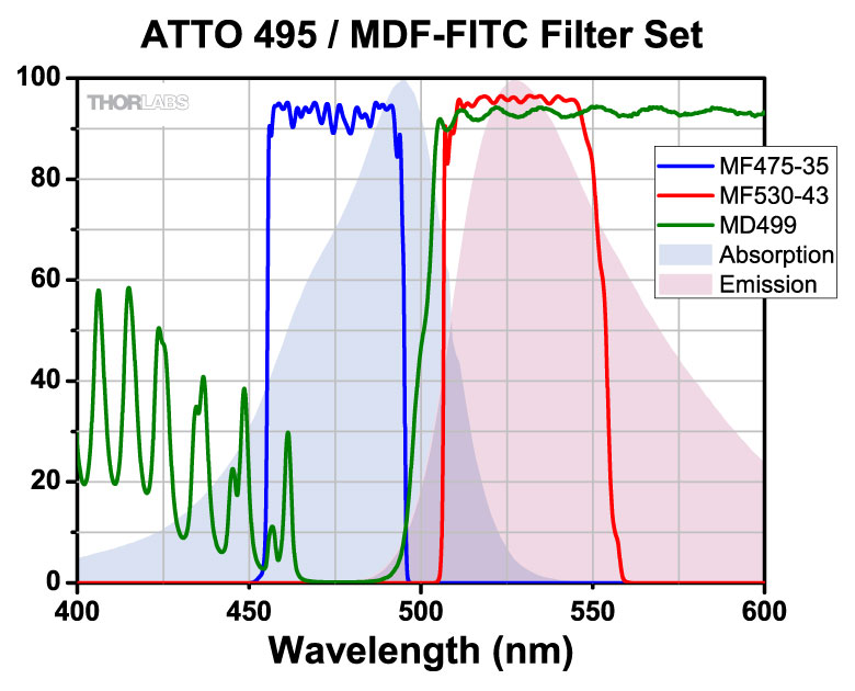
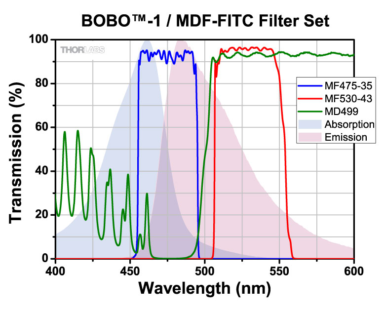
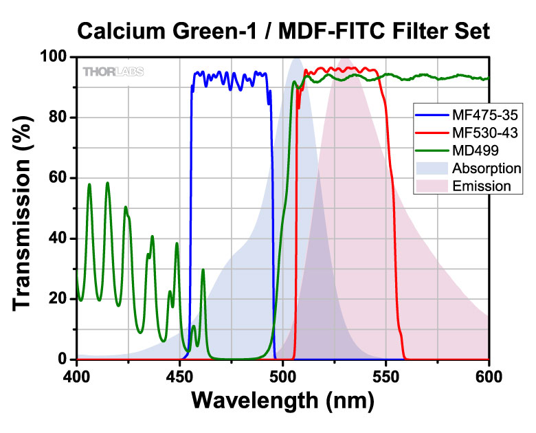
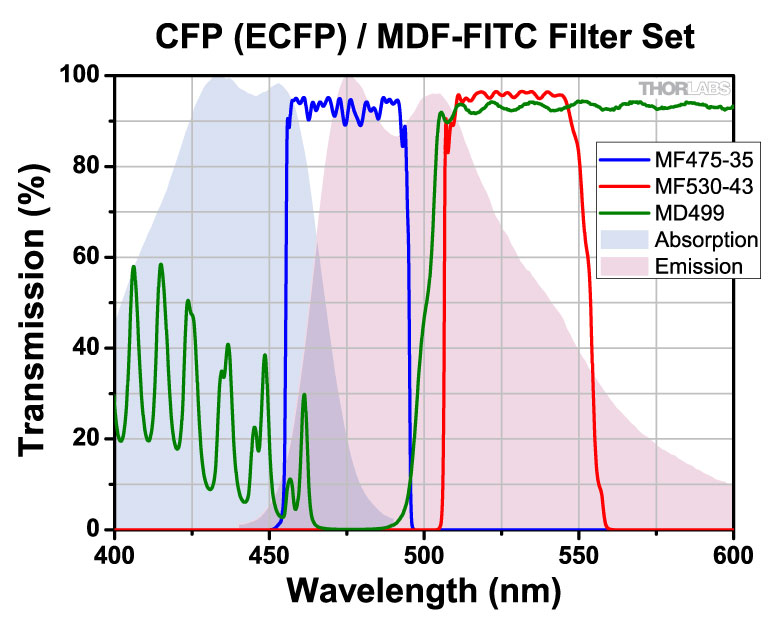
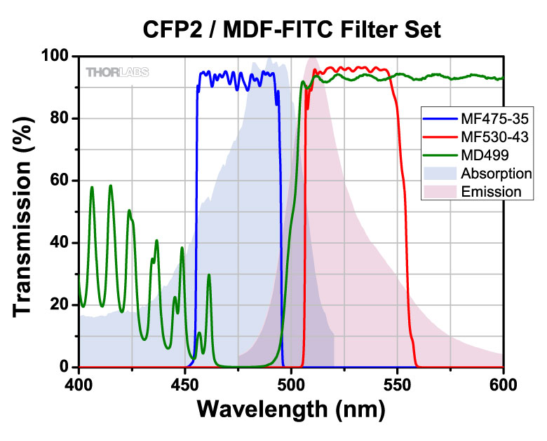
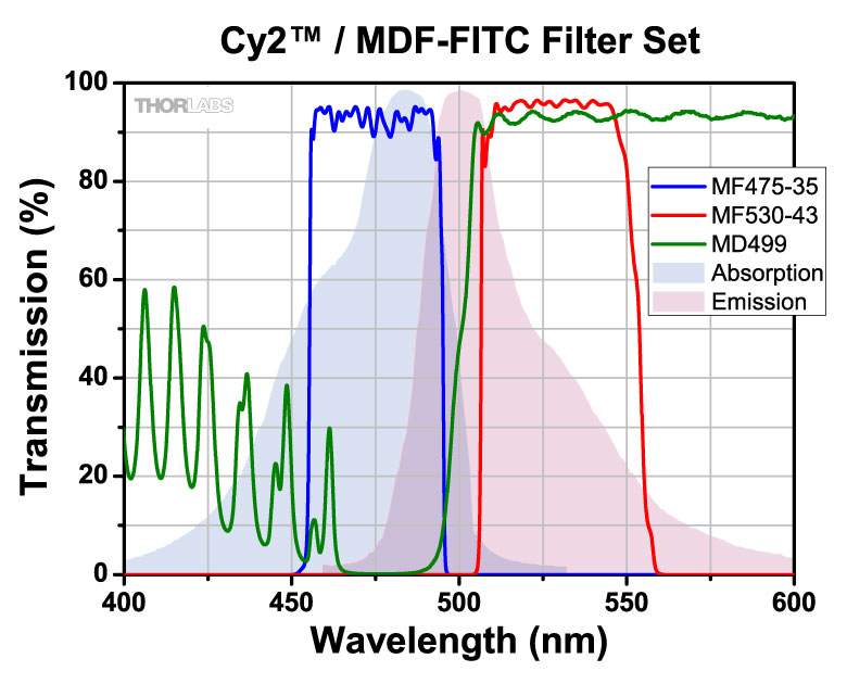
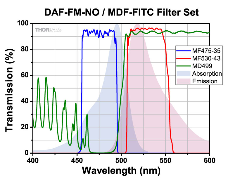
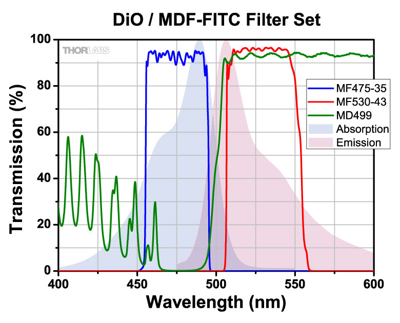
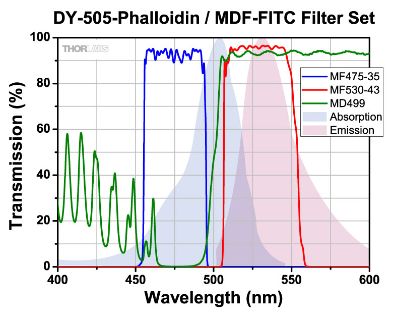
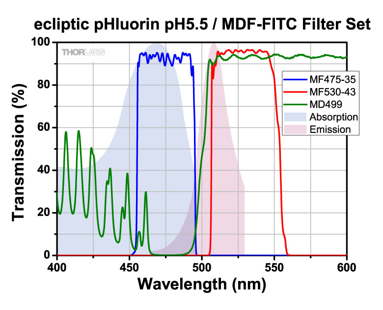
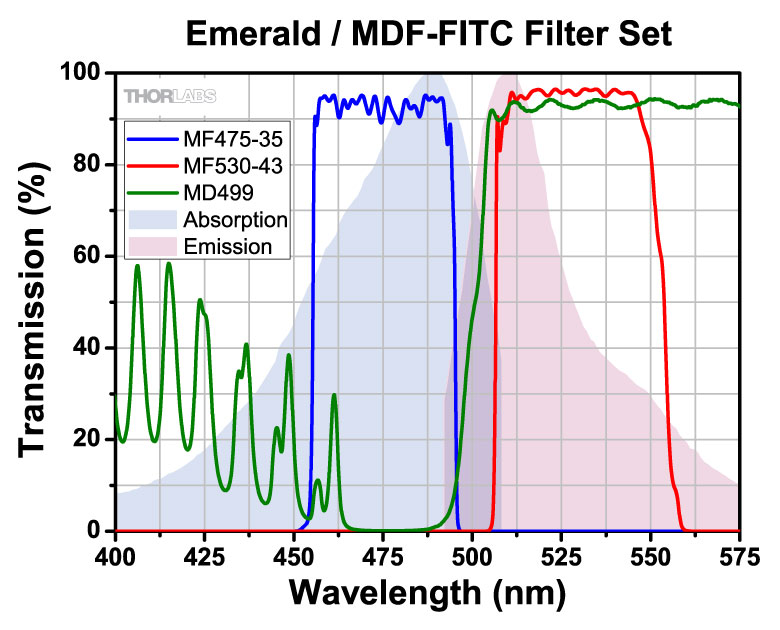
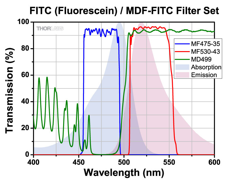
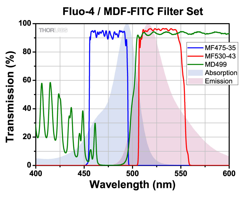
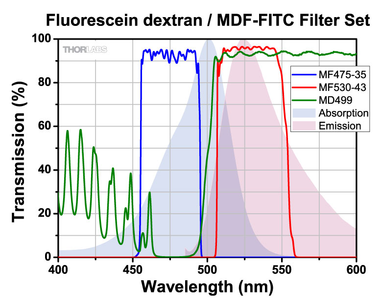
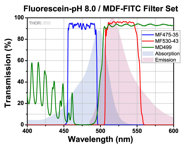
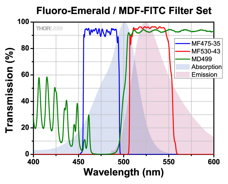
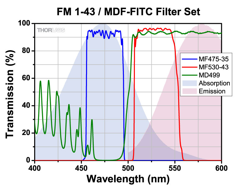
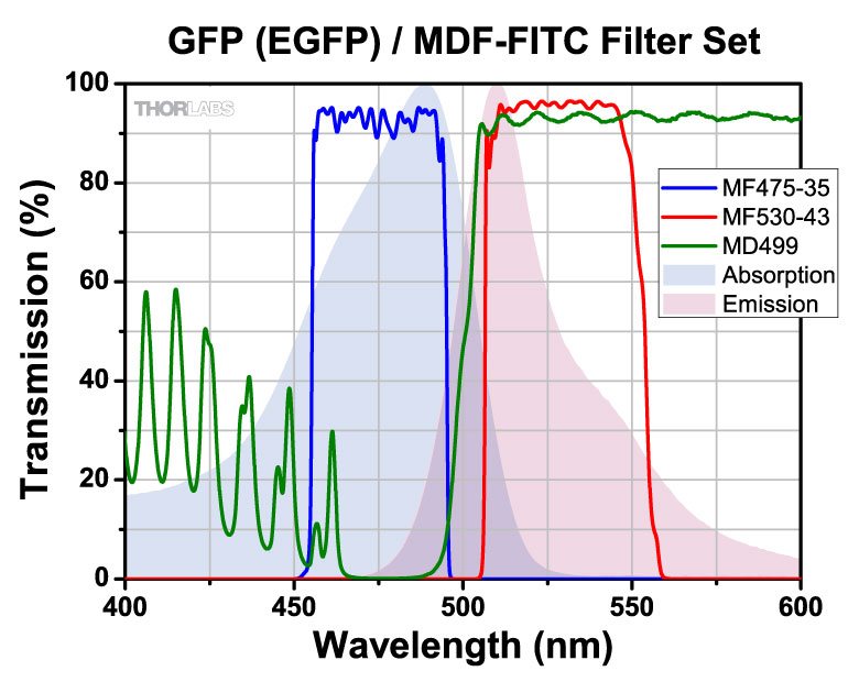
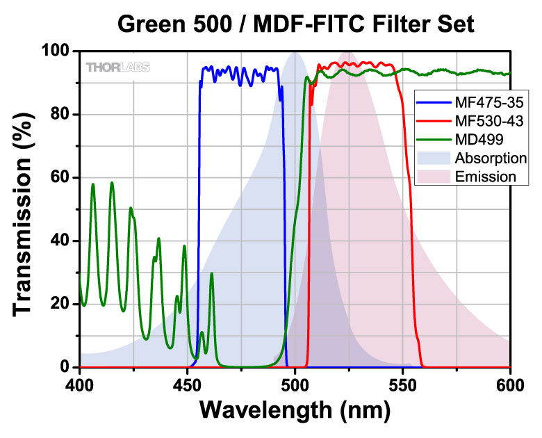
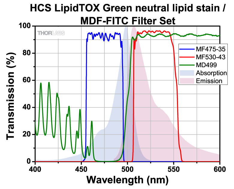
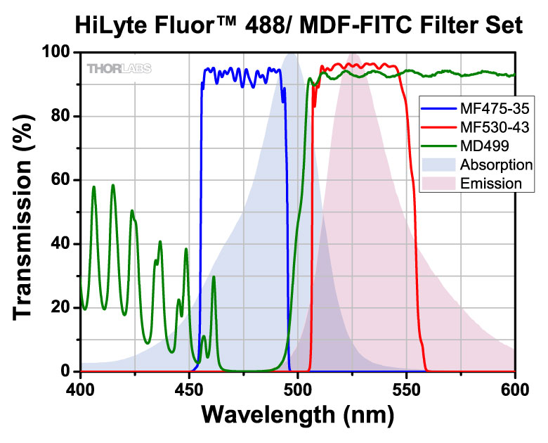
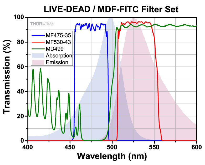
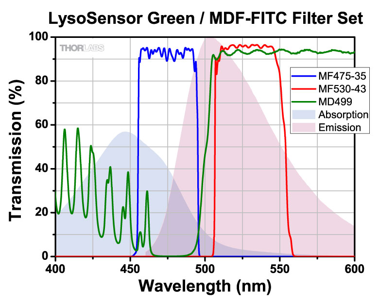
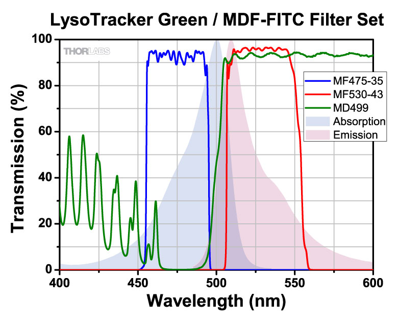
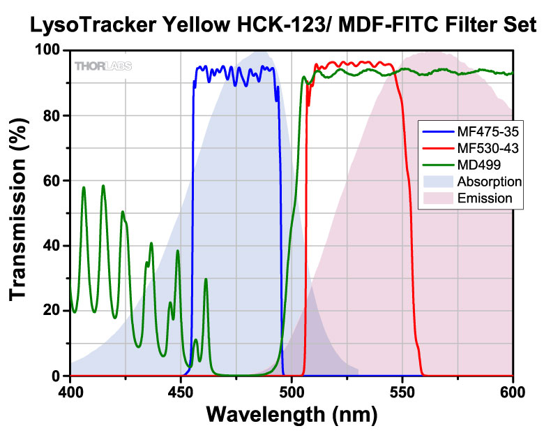
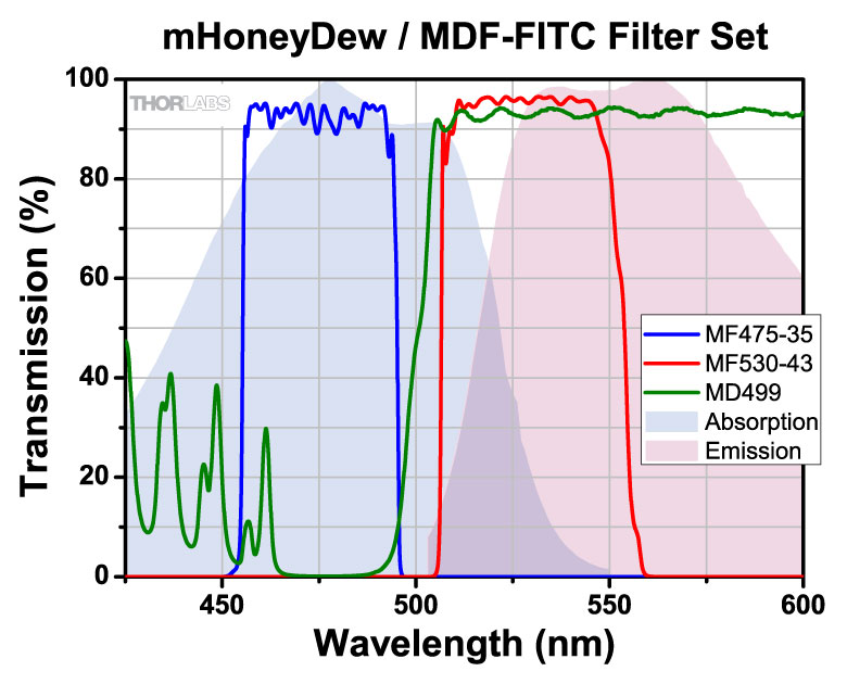
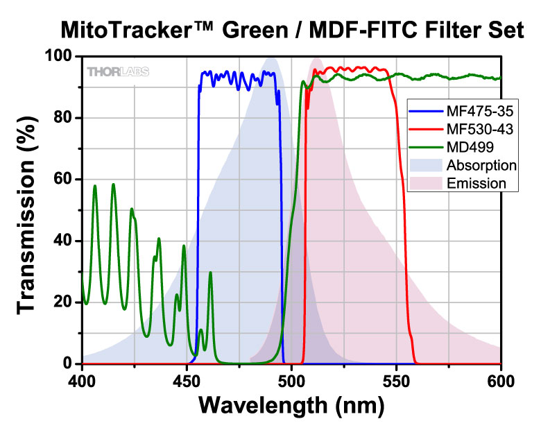
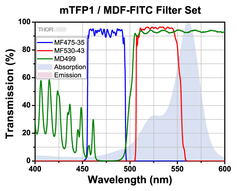
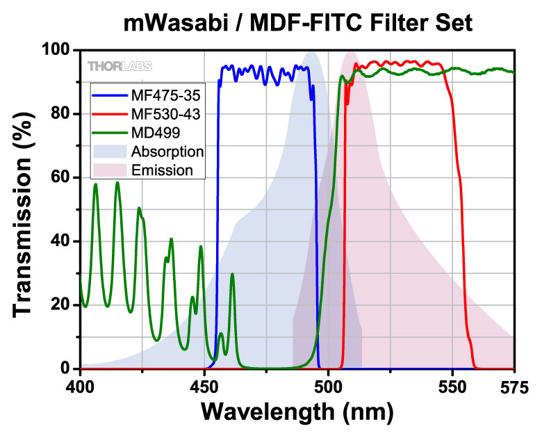
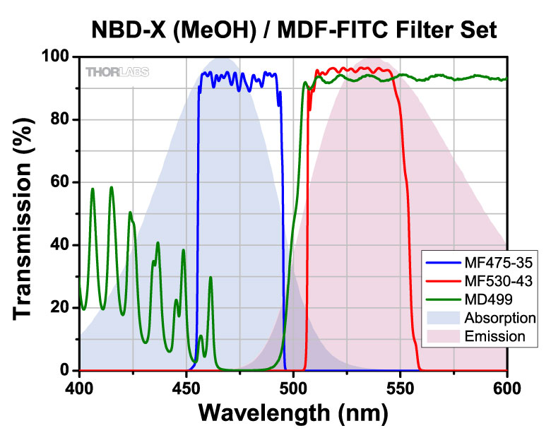
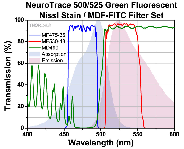
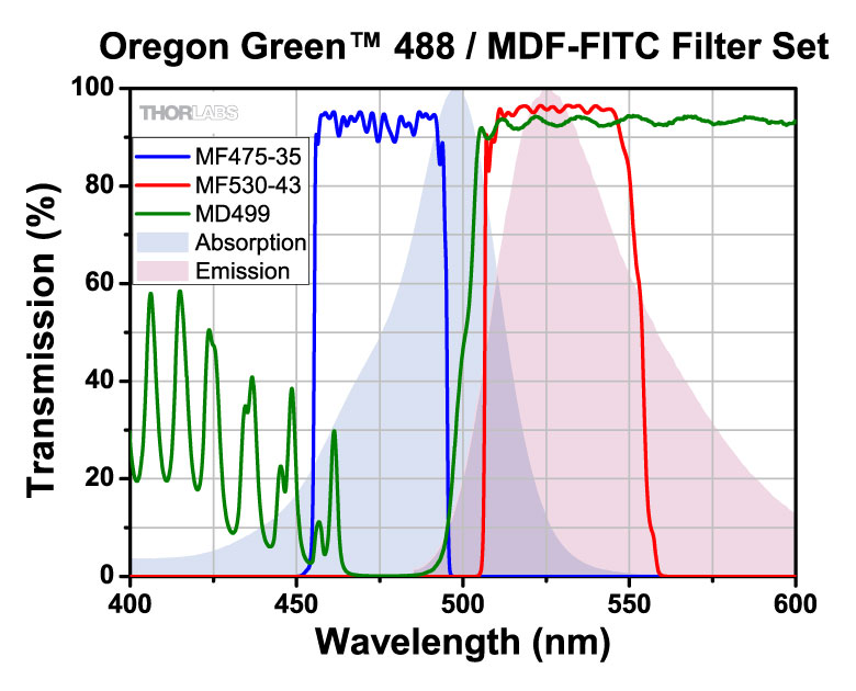
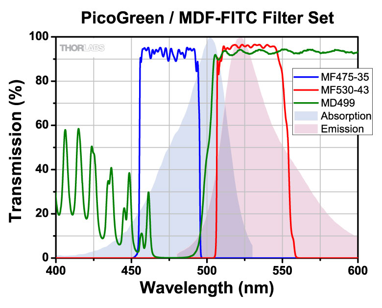
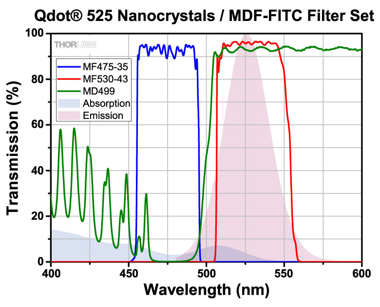
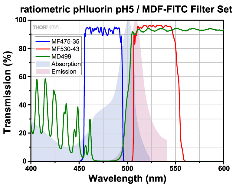
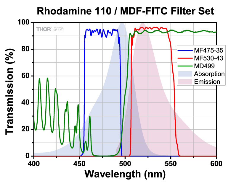
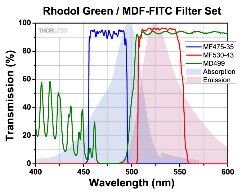
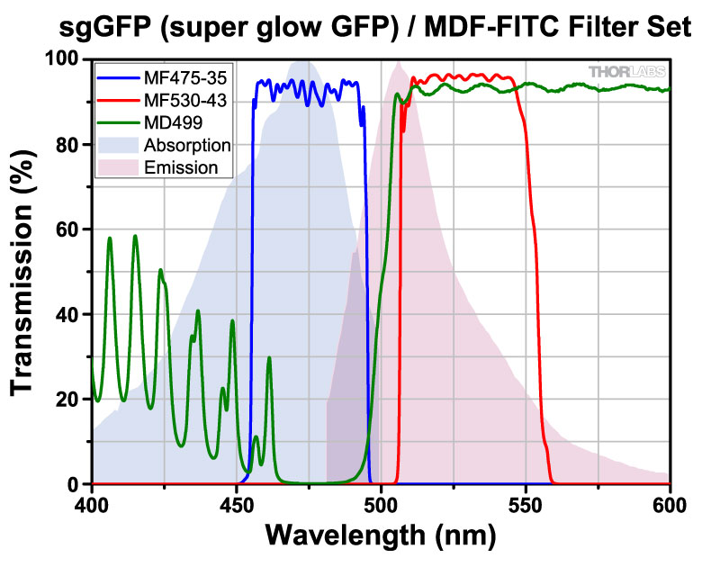
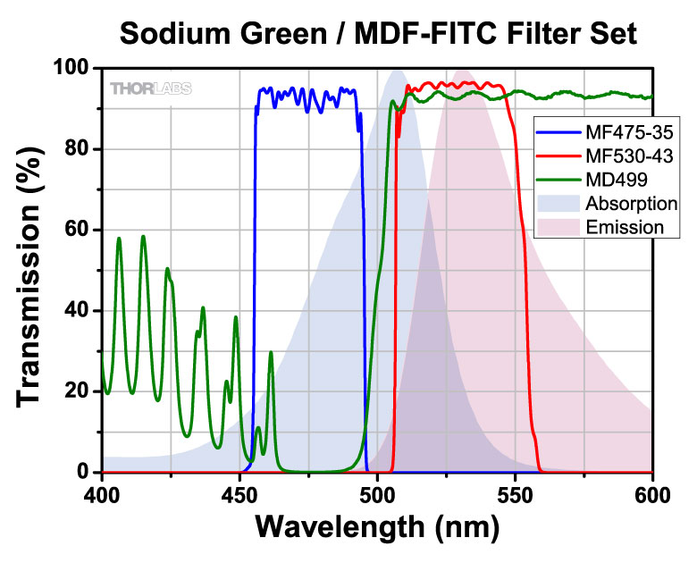
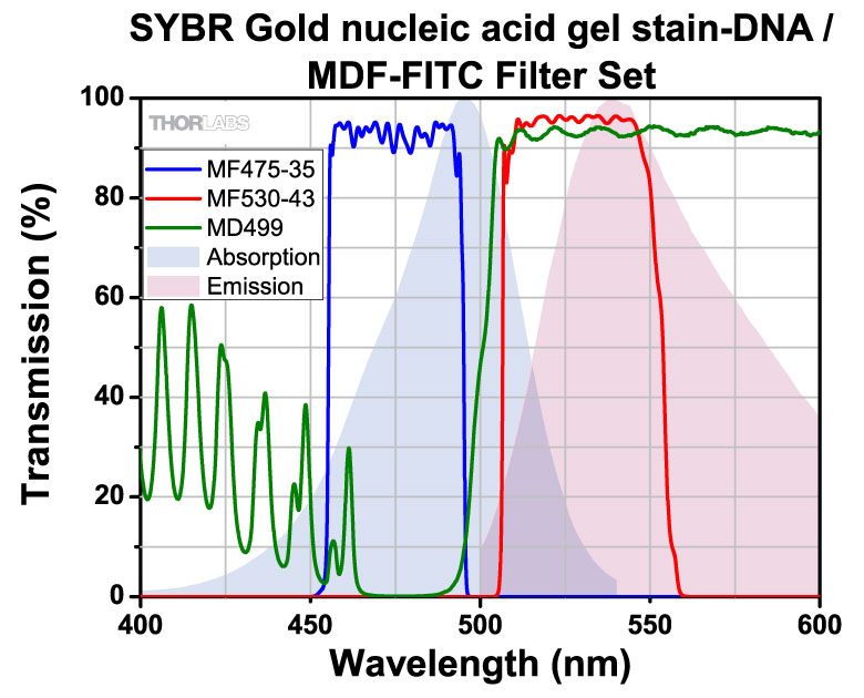
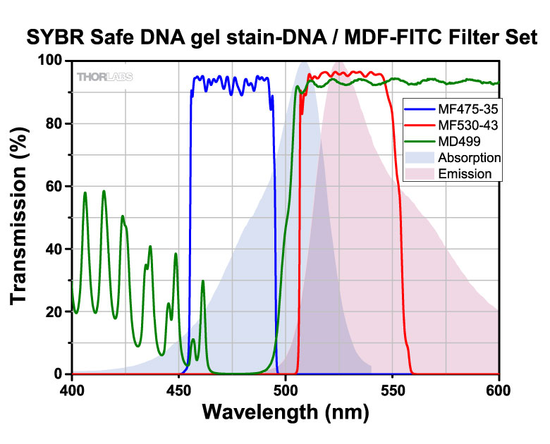
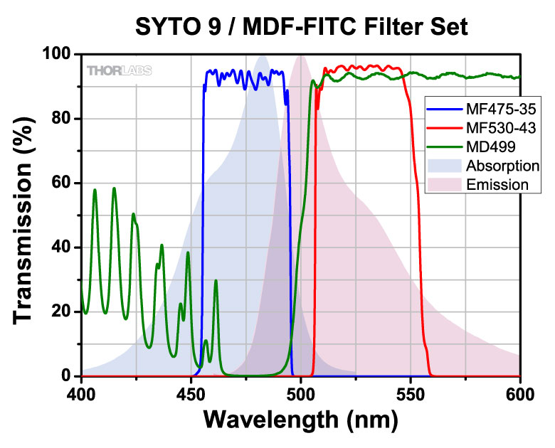
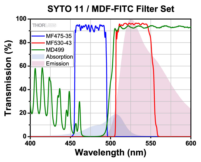
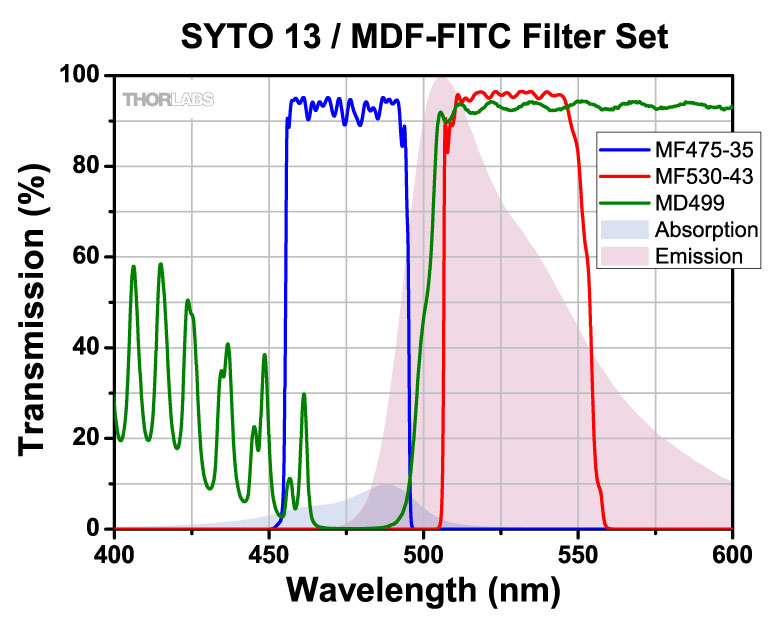
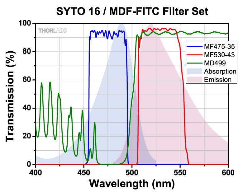
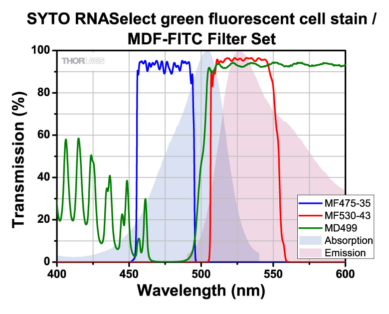
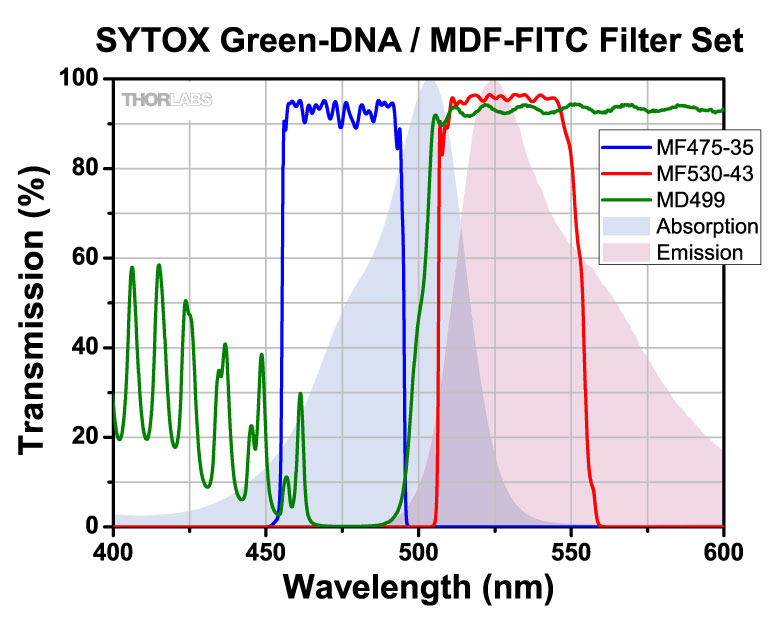
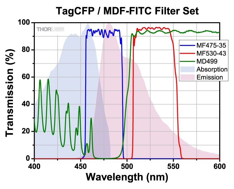
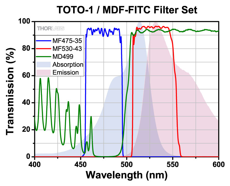
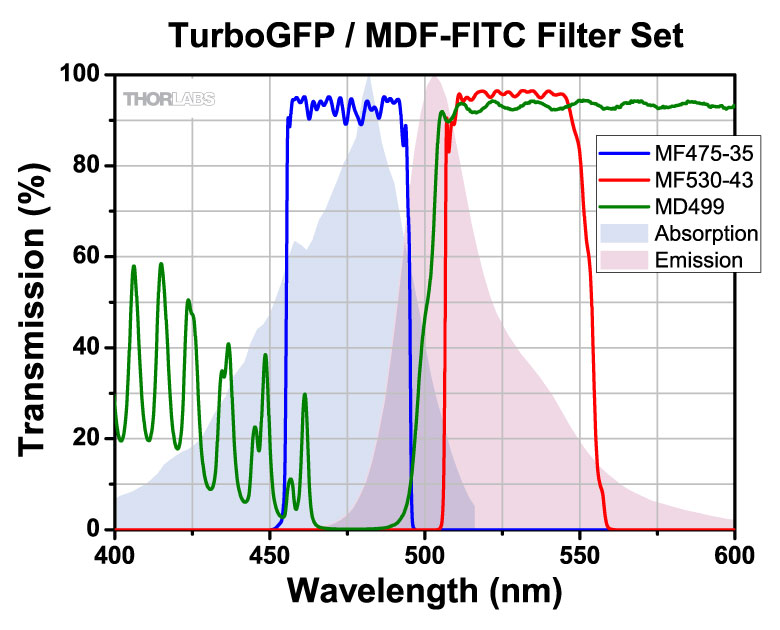
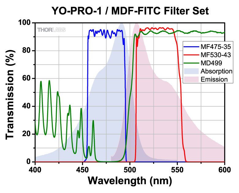
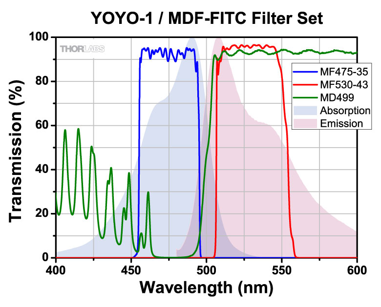
| MDF-FITC | FITC |
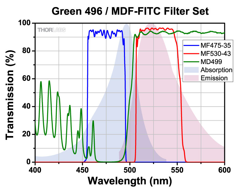
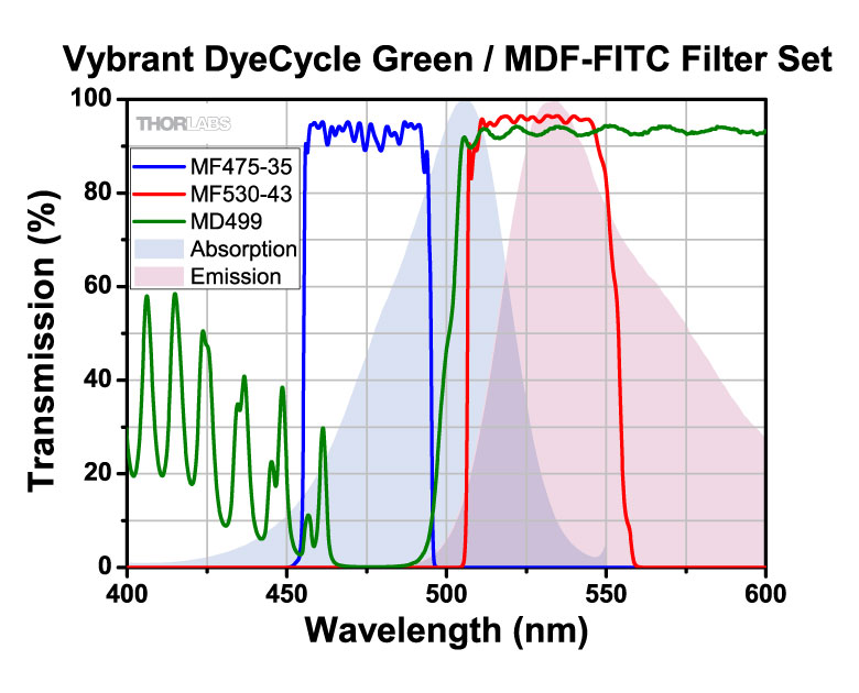
Excitation | 475 nm | 35 nm | - | - | - | |
| Emission | 530 nm | 43 nm | - | - | - | |||
| Dichroic | - | - | 470 - 490 nm | 508 - 675 nm | Rabs < 2% from 400 to 800 nm |
|||
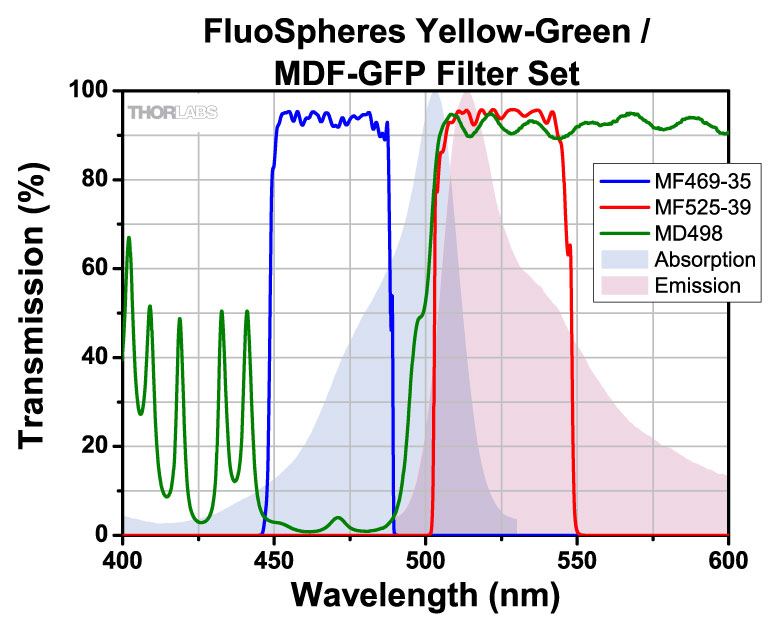
| MDF-GFP2 | GFP Alexa Fluor® 488 |
Excitation | 482 nm | 18 nm | - | - | - | |
| Emission | 520 nm | 28 nm | - | - | - | |||
| Dichroic | - | - | 350 - 488 nm | 502 - 950 nm | - | |||
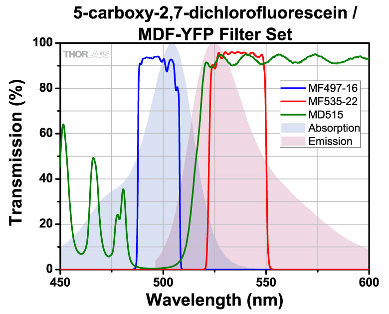
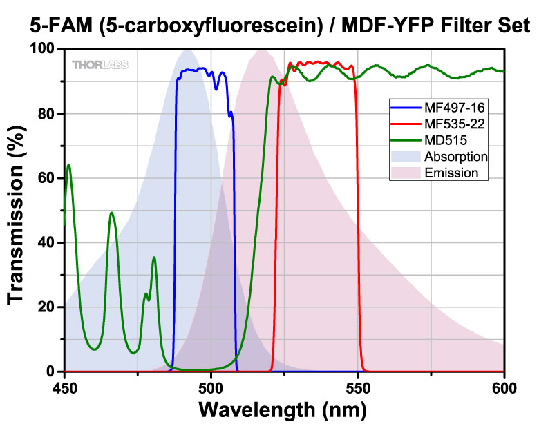
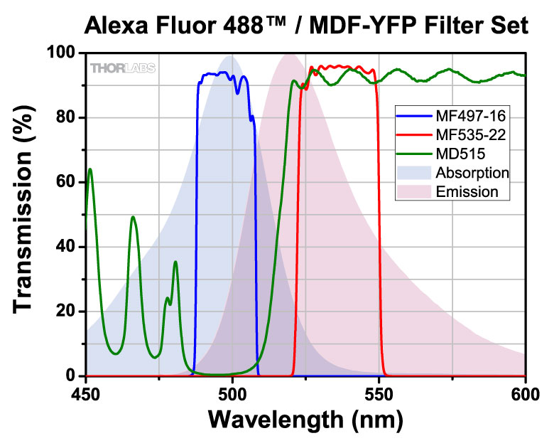
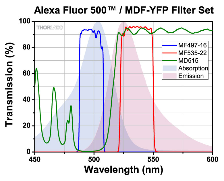
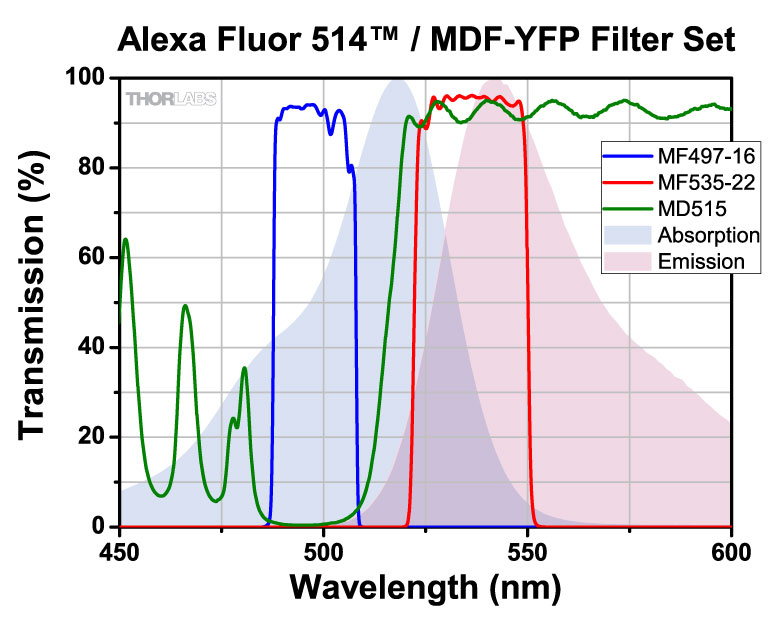
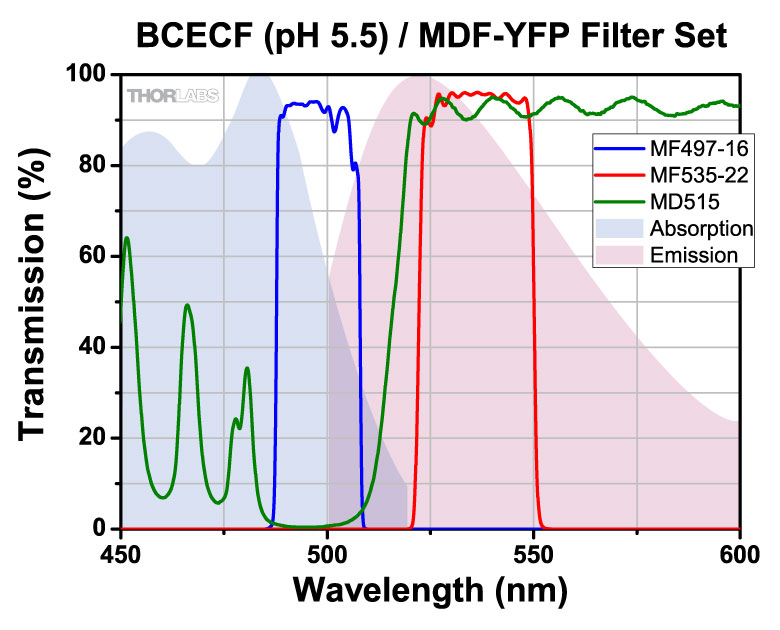
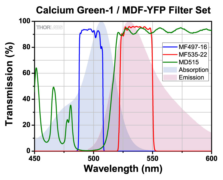
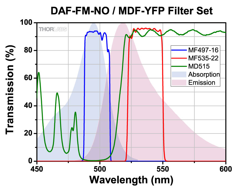
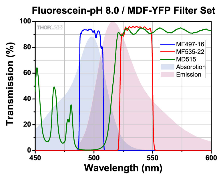
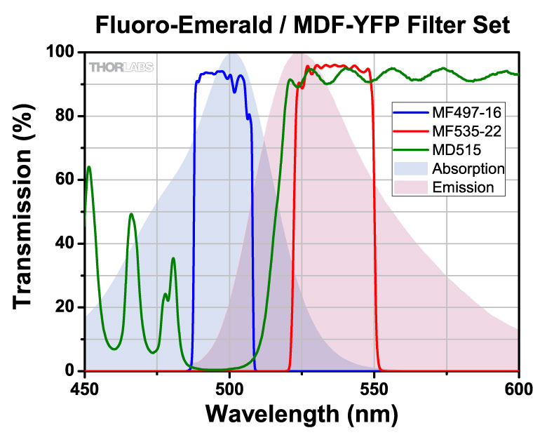
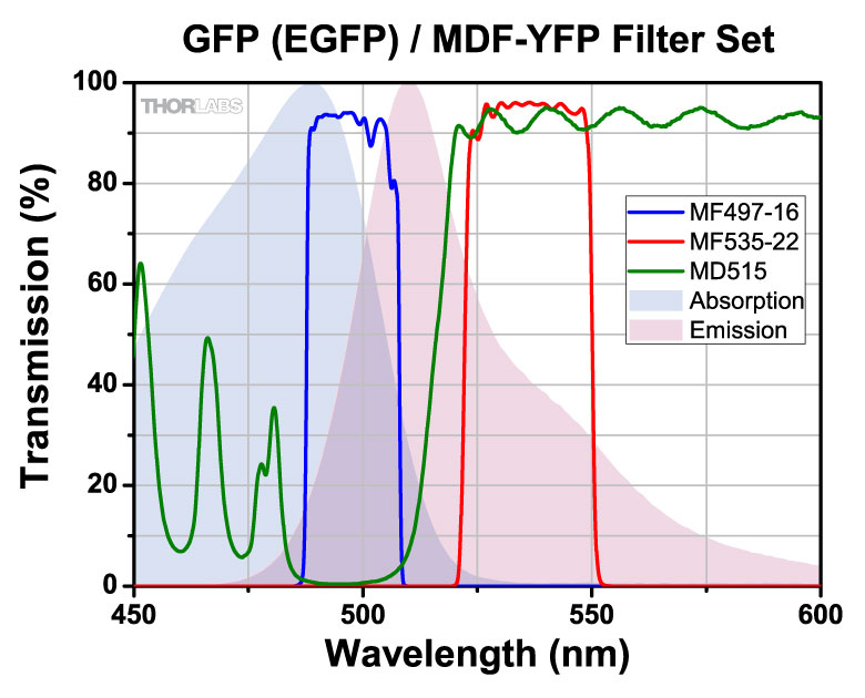
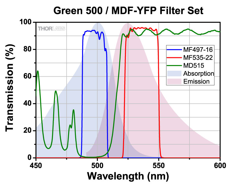
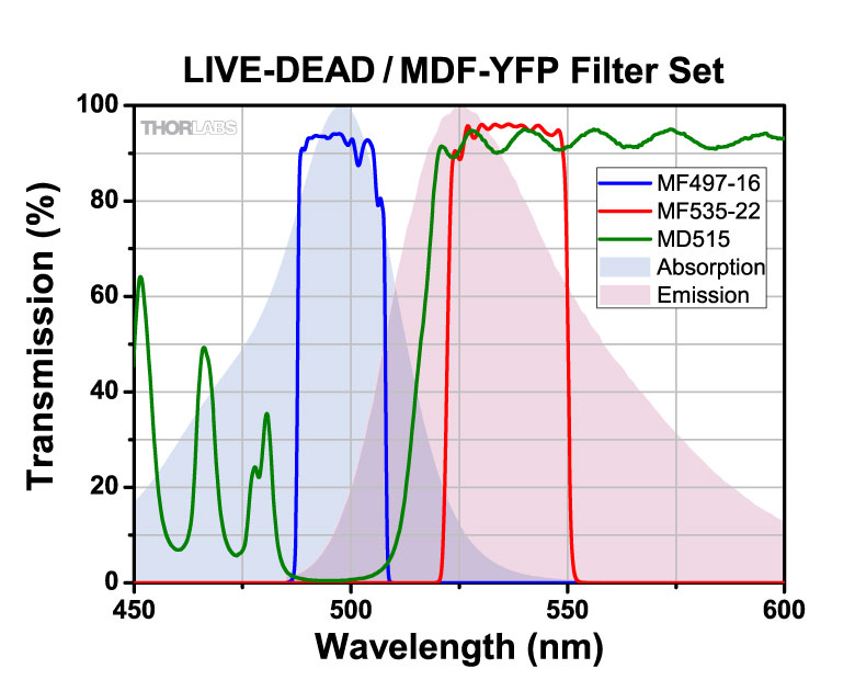
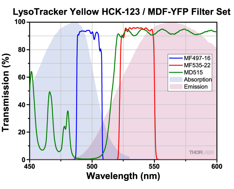
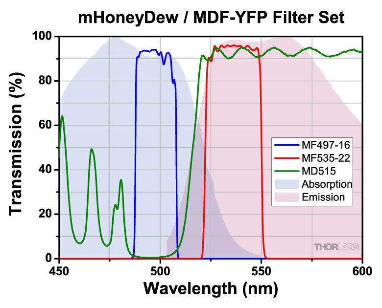
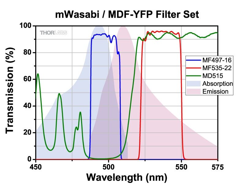
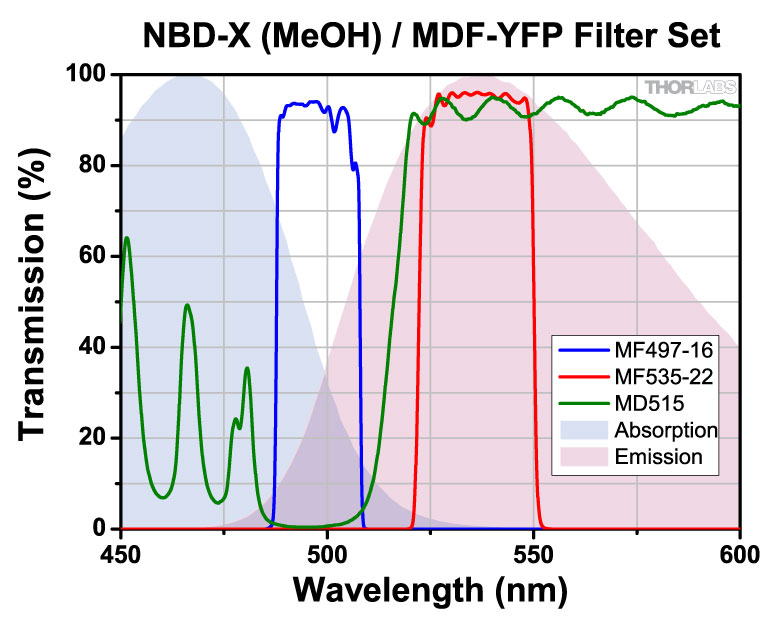
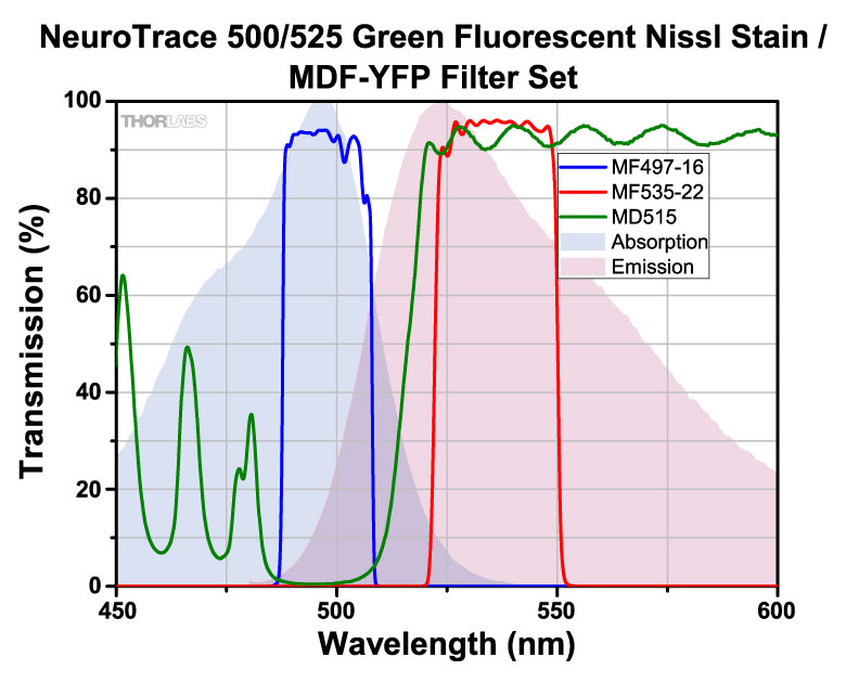
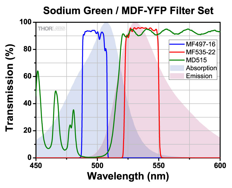
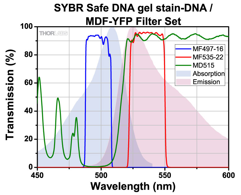
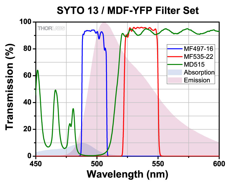
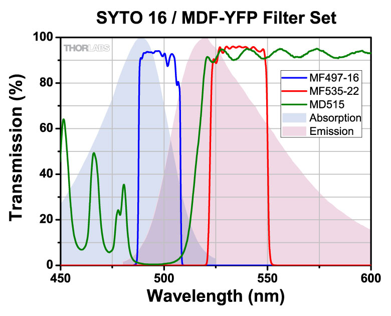
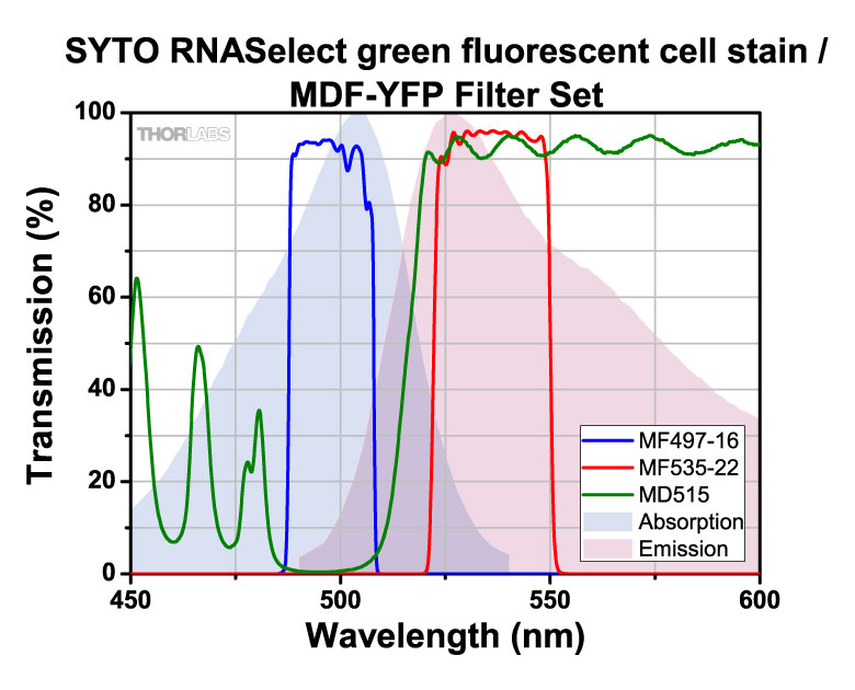
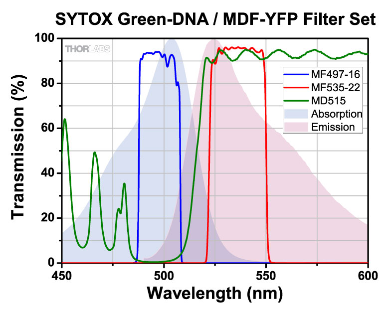
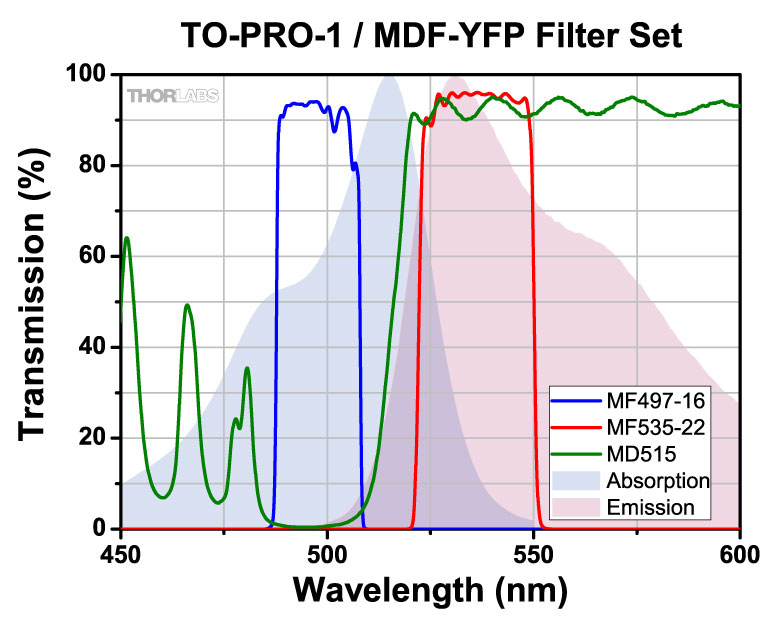
| MDF-YFP | YFP |
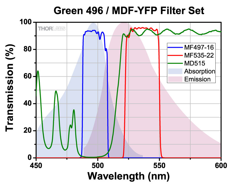
Excitation | 497 nm | 16 nm | - | - | - | |
| Emission | 535 nm | 22 nm | - | - | - | |||
| Dichroic | - | - | 490 - 510 nm | 520 - 700 nm | - | |||
| MDF-TOM | tdTomato | Excitation | 531 nm | 40 nm | - | - | - | |
| Emission | 593 nm | 40 nm | - | - | - | |||
| Dichroic | - | - | 350 - 555 nm | 569 - 950 nm | - | |||
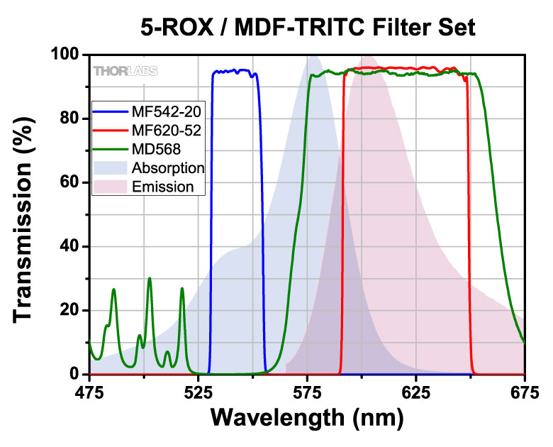
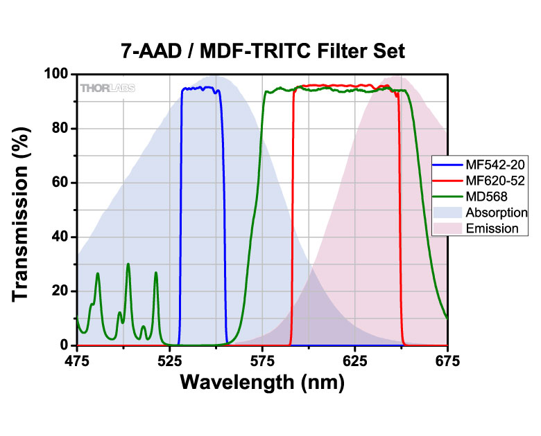
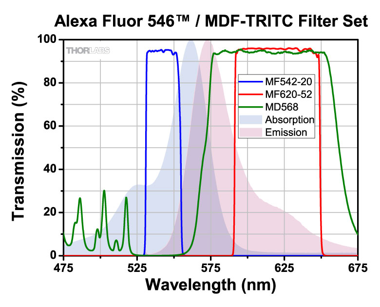
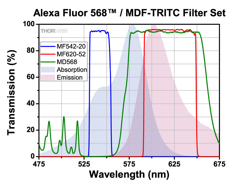
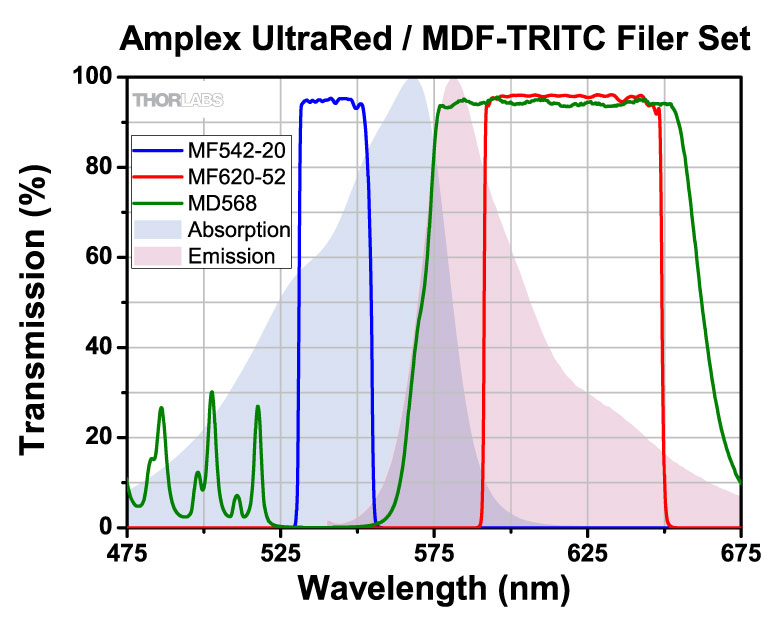
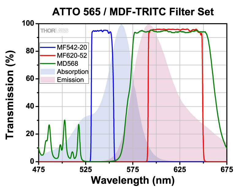
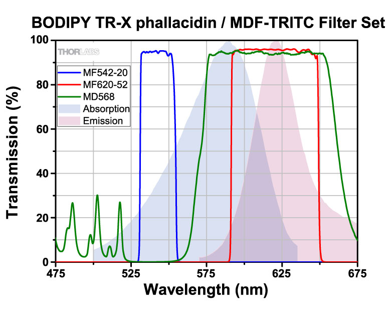
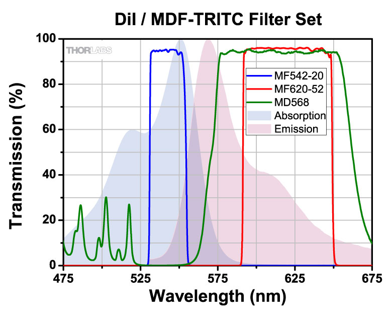
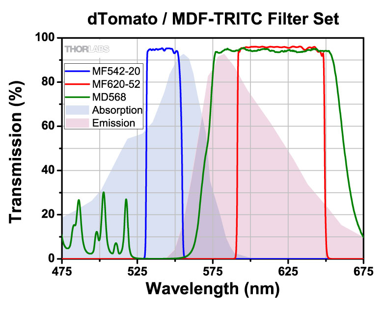
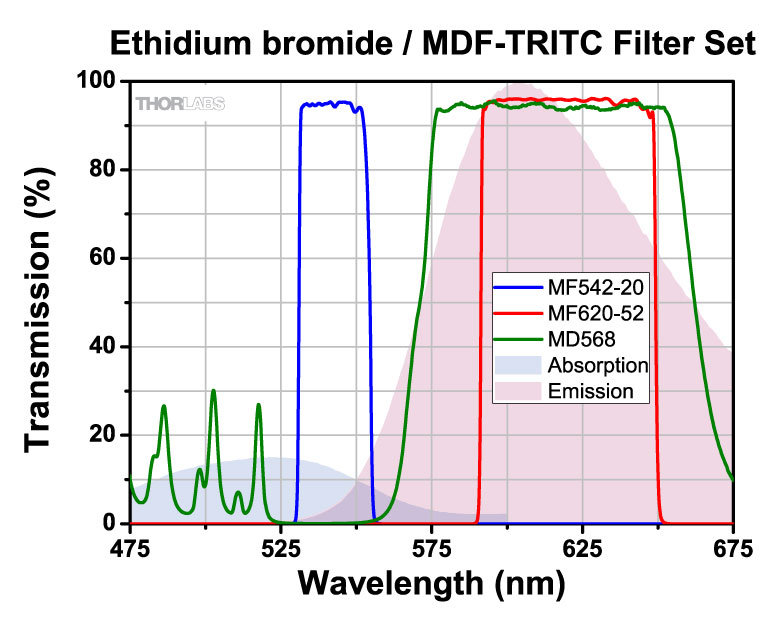
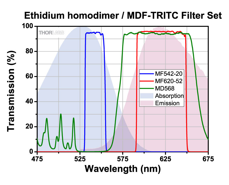
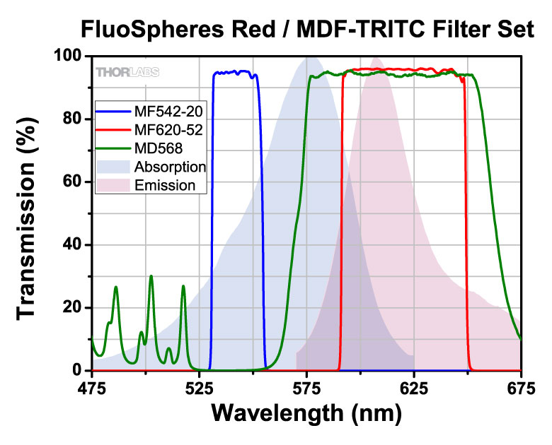
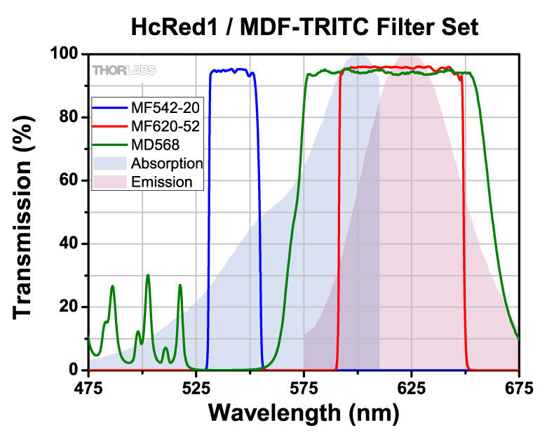
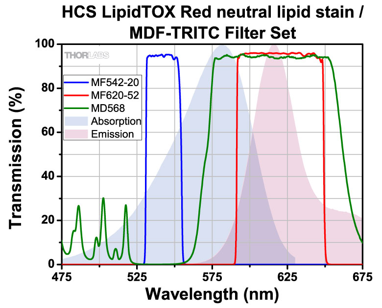
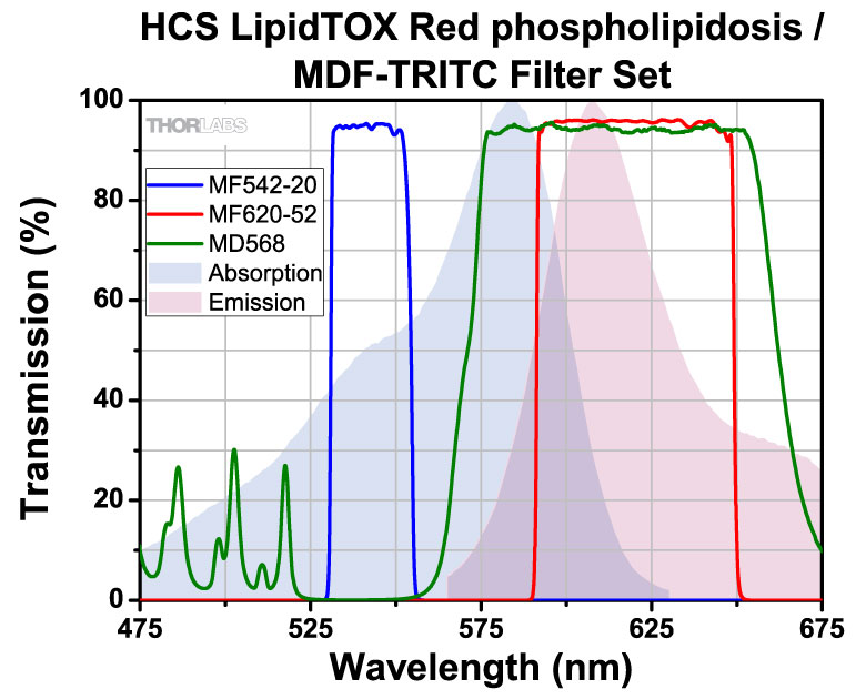
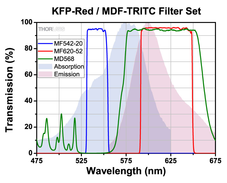
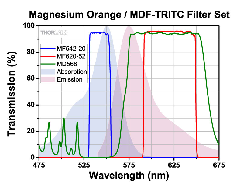
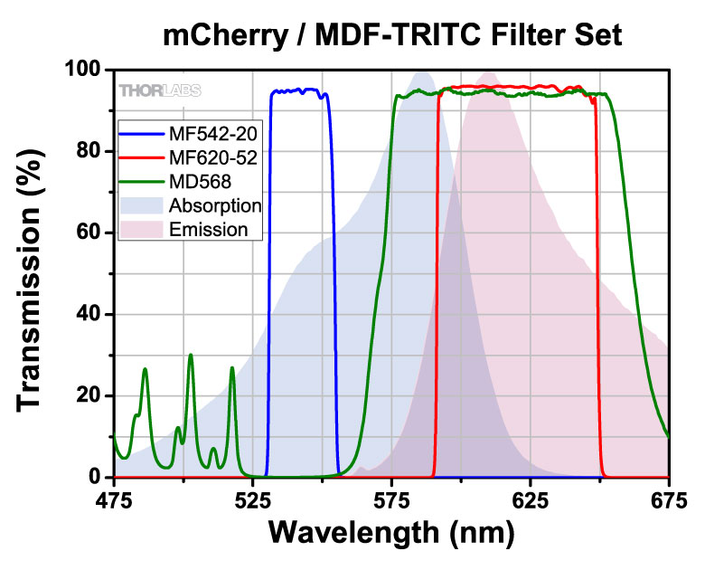
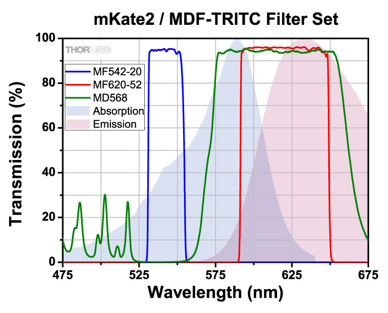
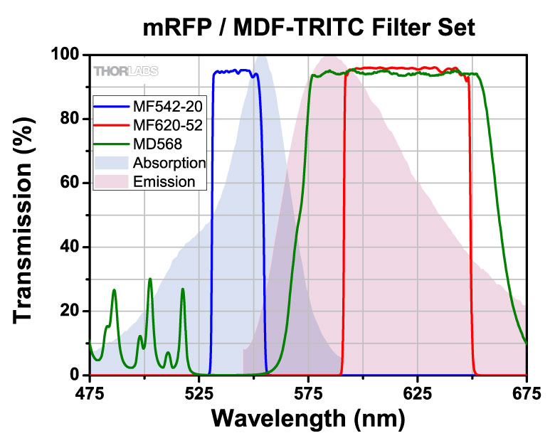
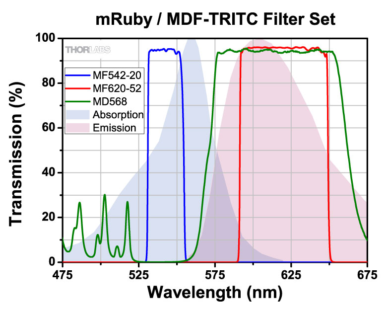
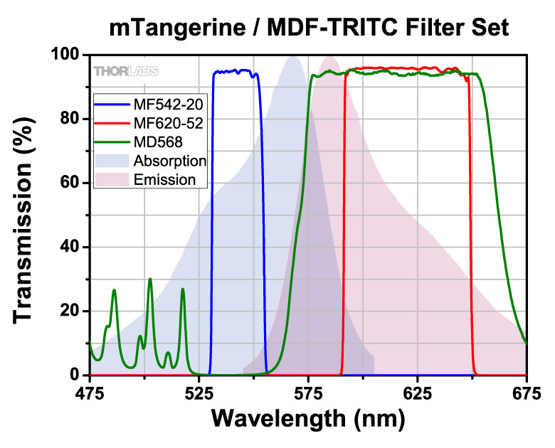
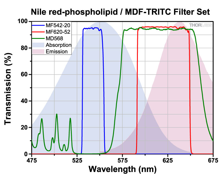
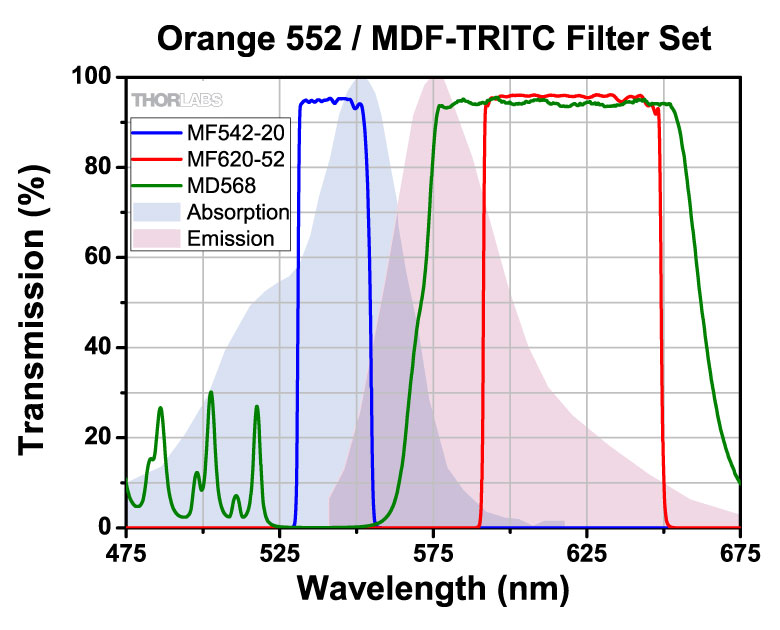
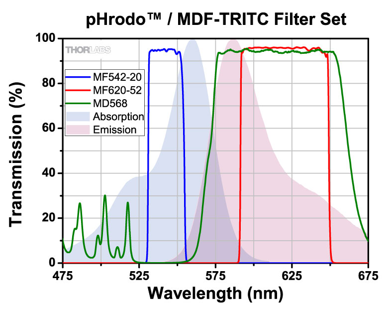
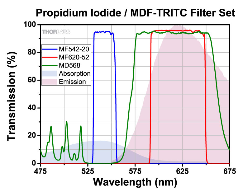
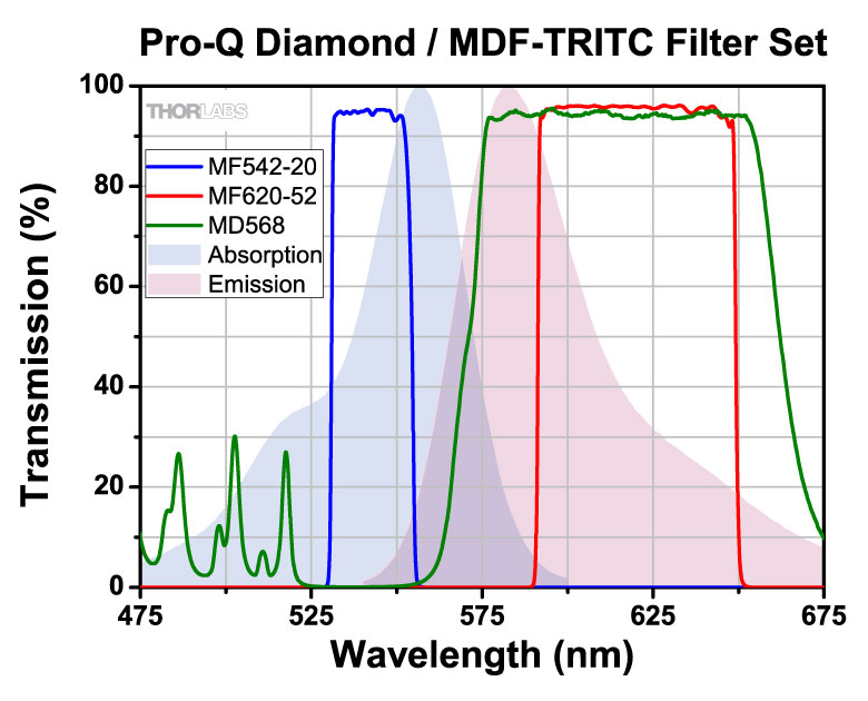
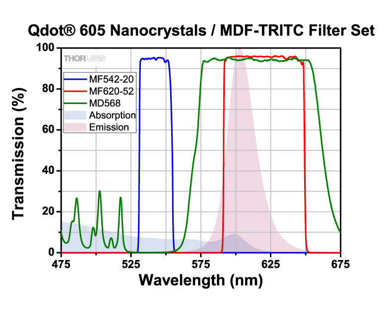
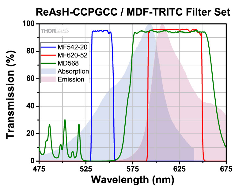
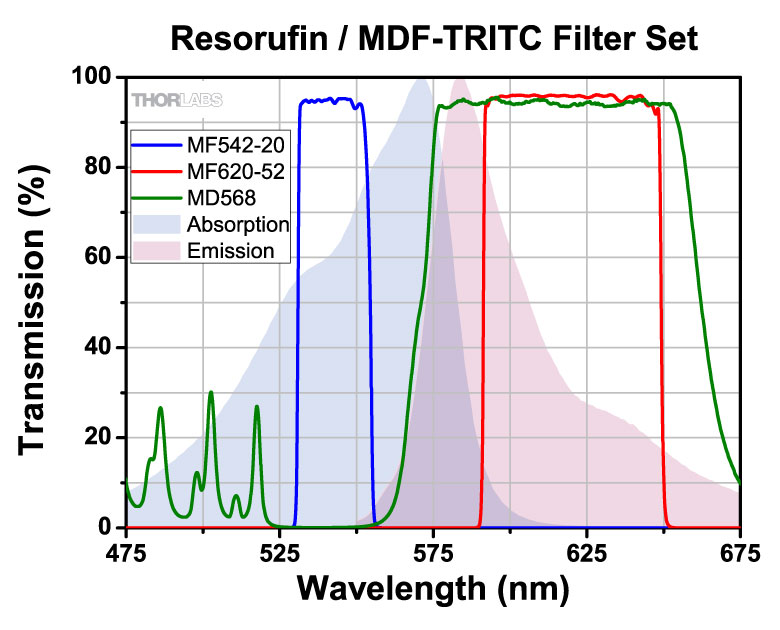
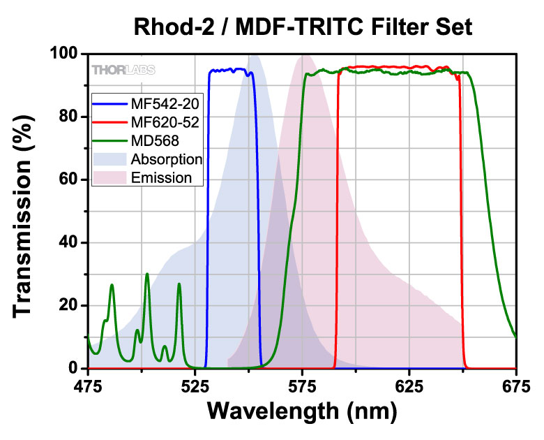
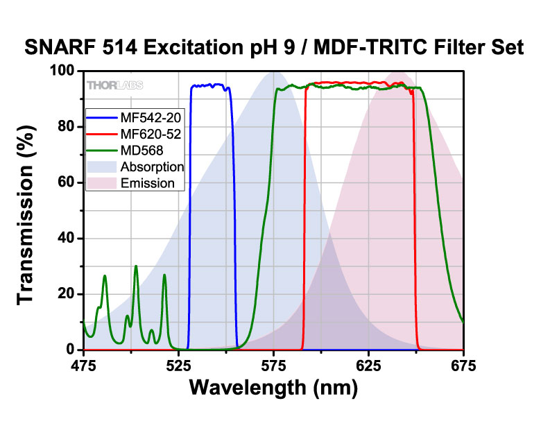
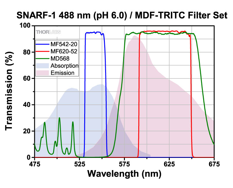
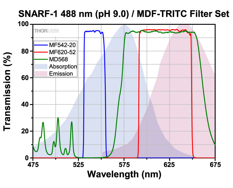
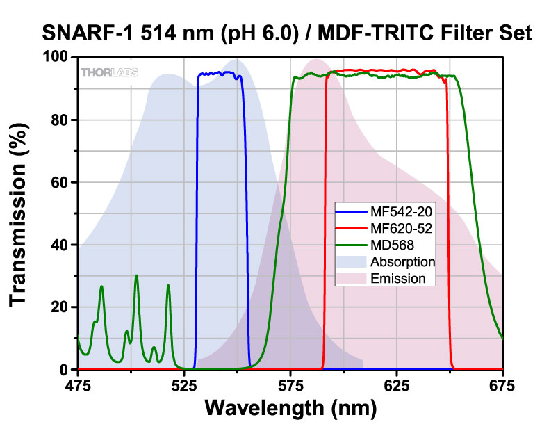
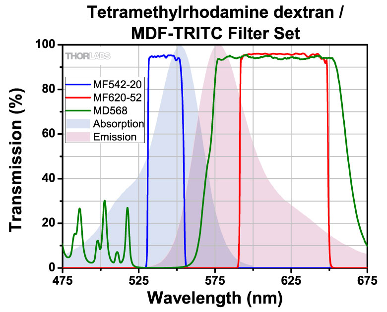
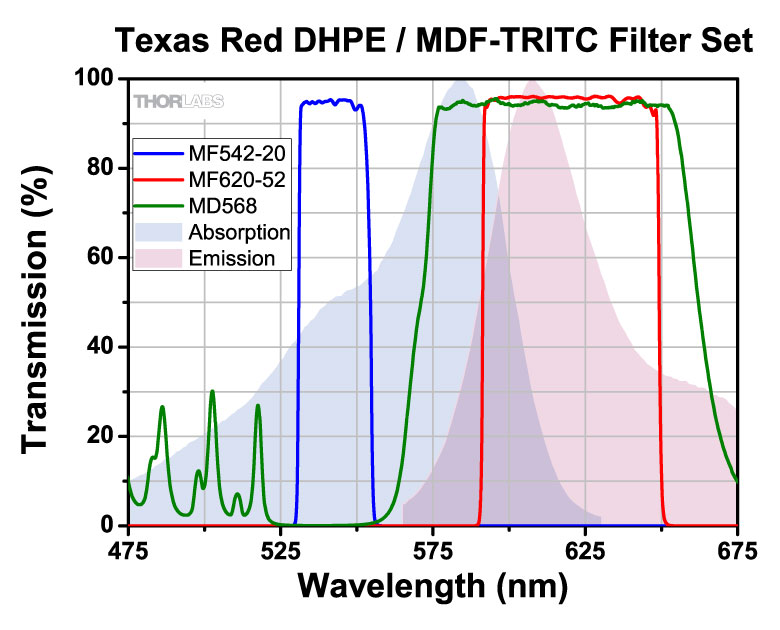
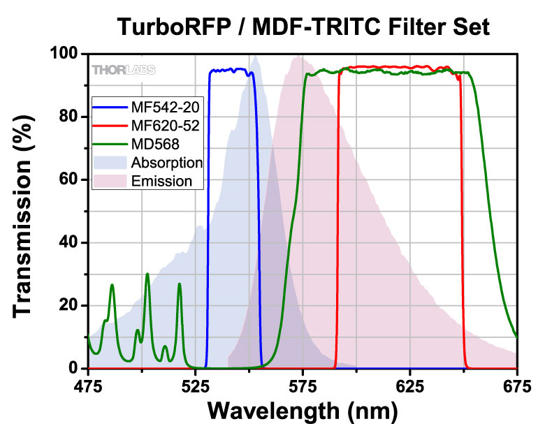
| MDF-TRITC | TRITC | Excitation | 542 nm | 20 nm | - | - | - | |
| Emission | 620 nm | 52 nm | - | - | - | |||
| Dichroic | - | - | 525 - 556 nm | 580 - 650 nm | Rabs < 2% from 400 to 800 nm |
|||
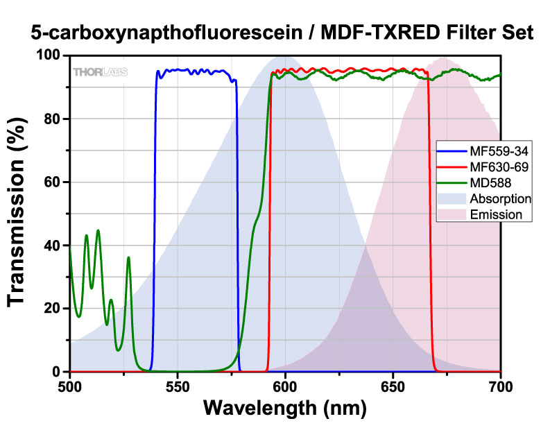
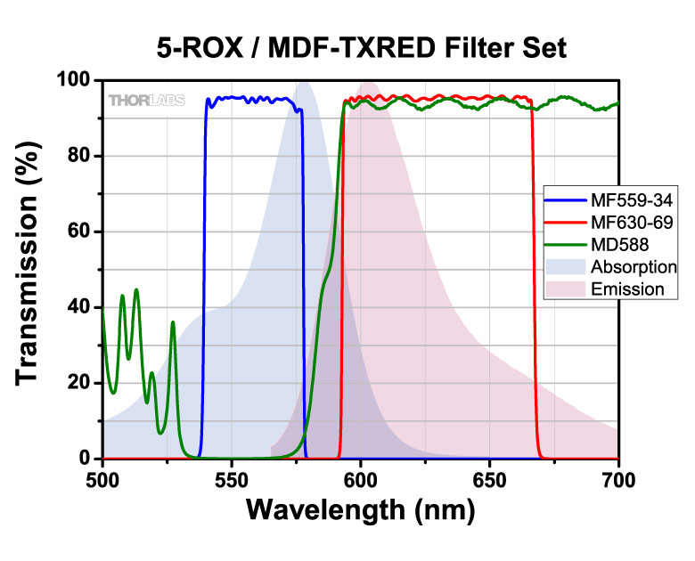
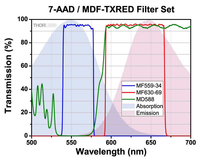
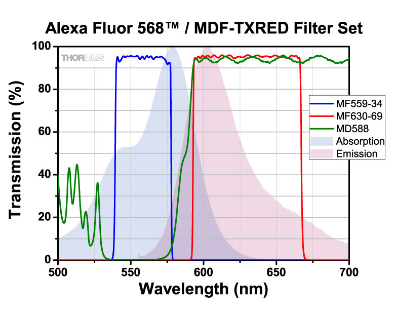
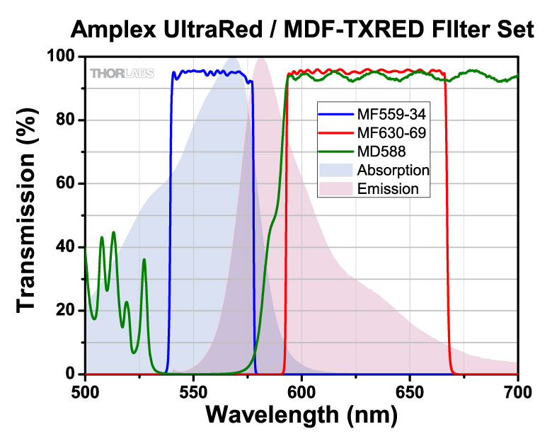
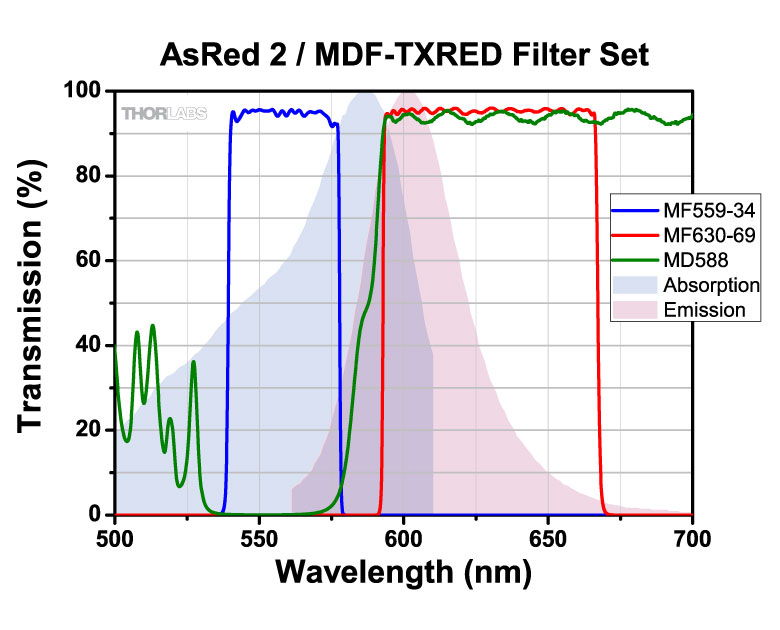
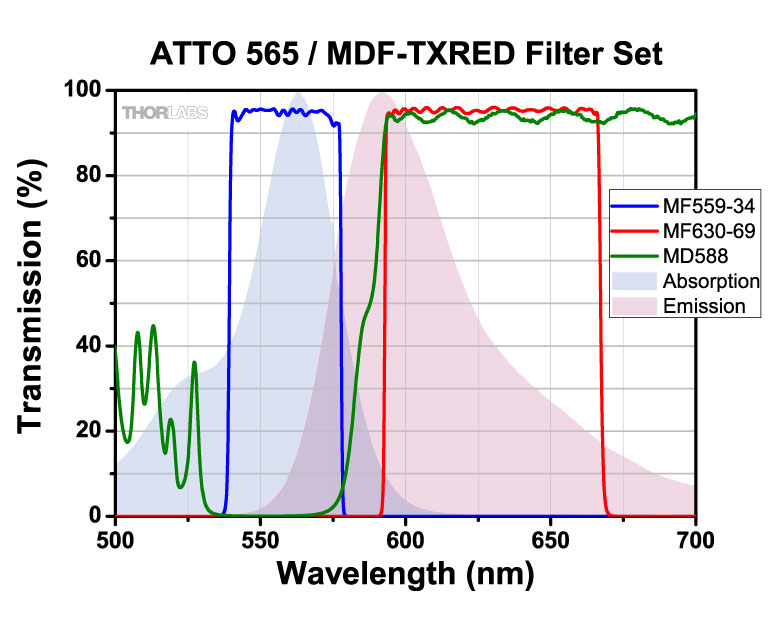
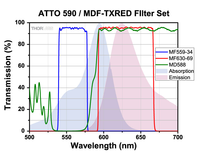
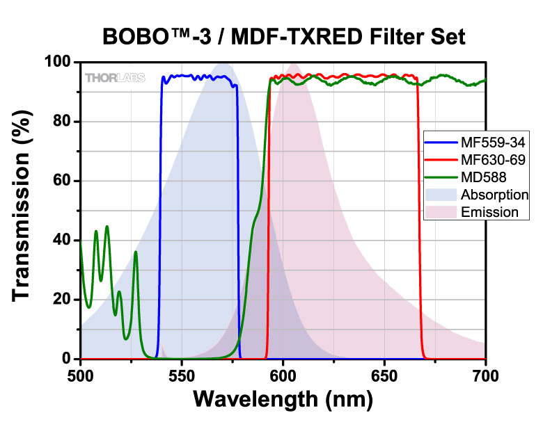
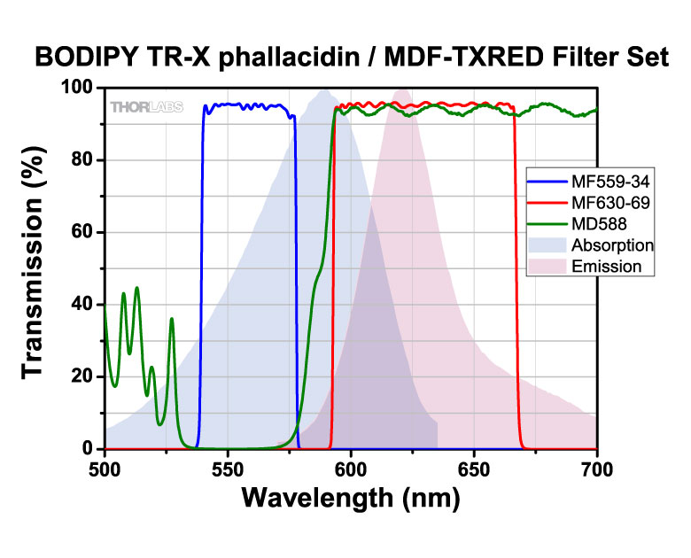
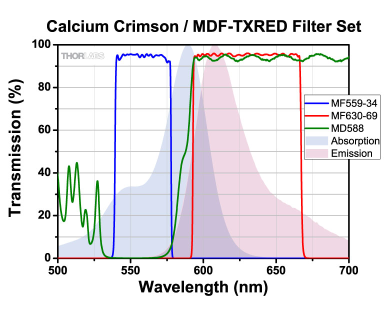
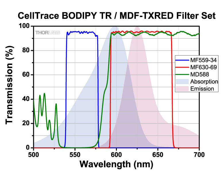
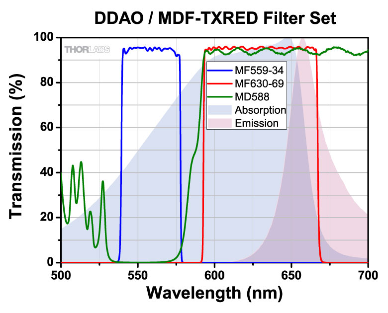
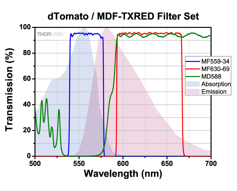
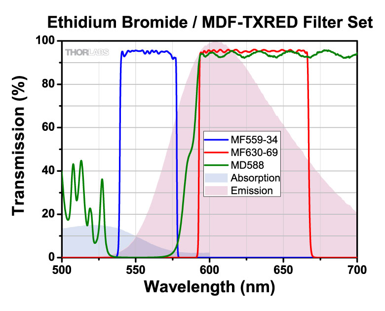
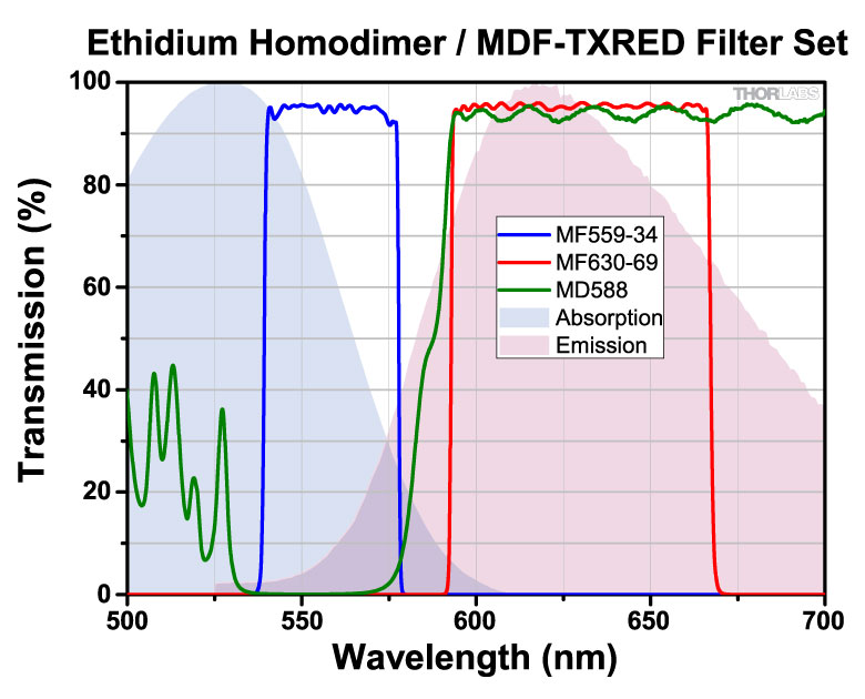
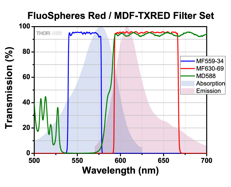
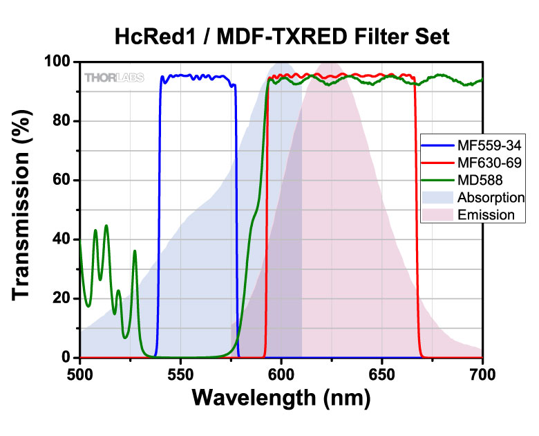
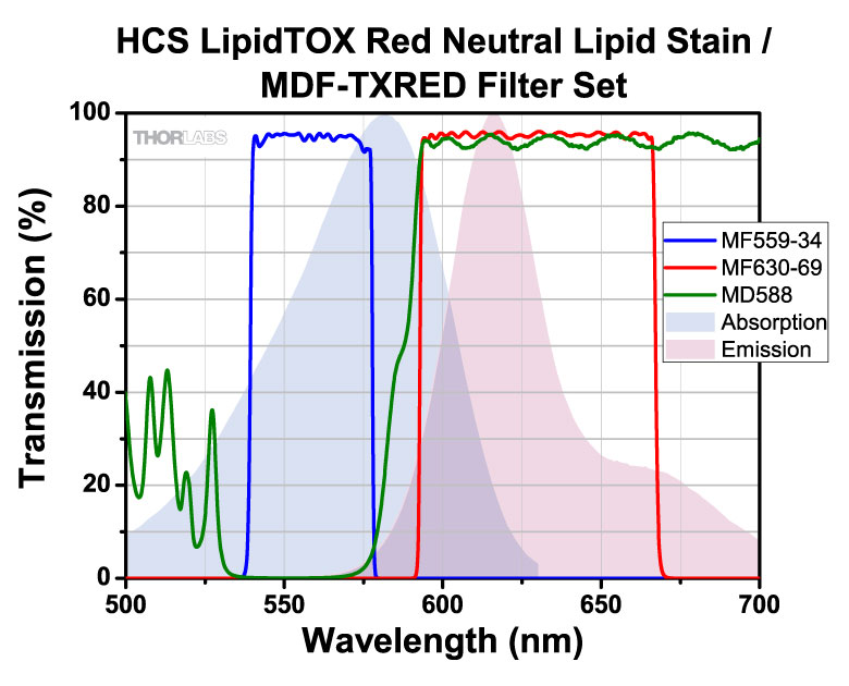
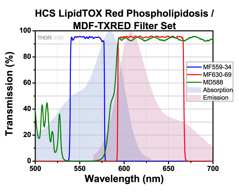
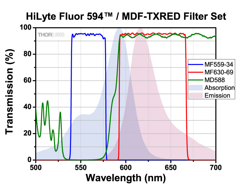
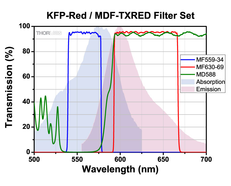
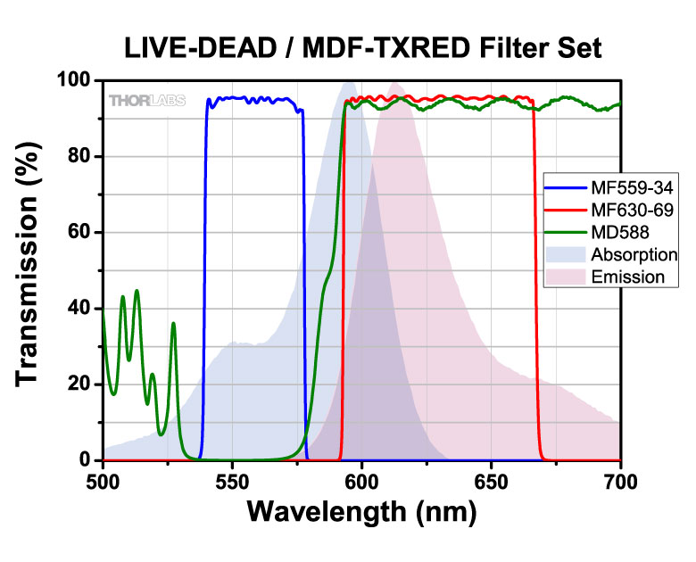
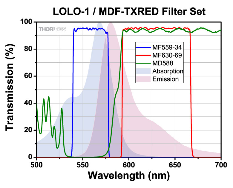
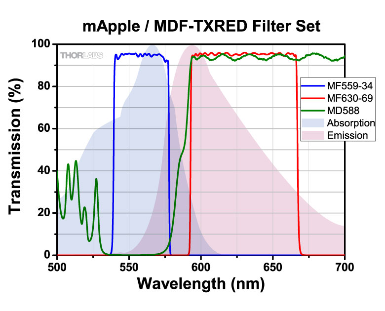
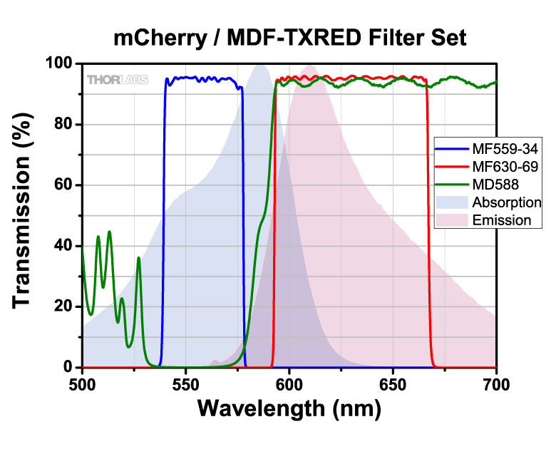
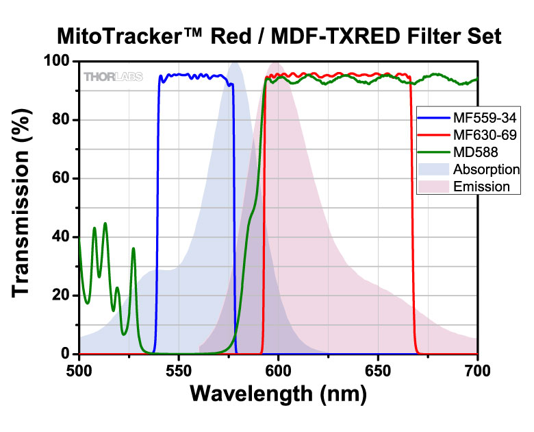
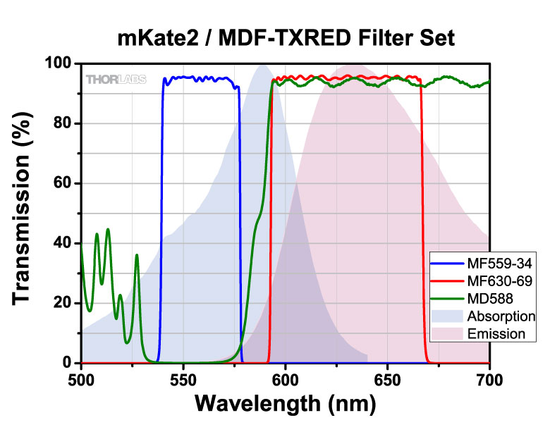
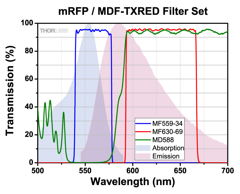
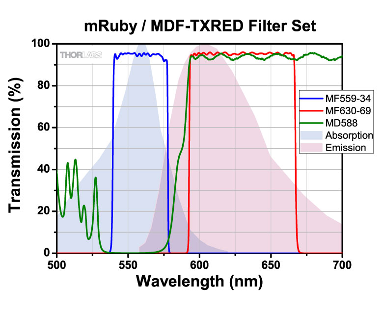
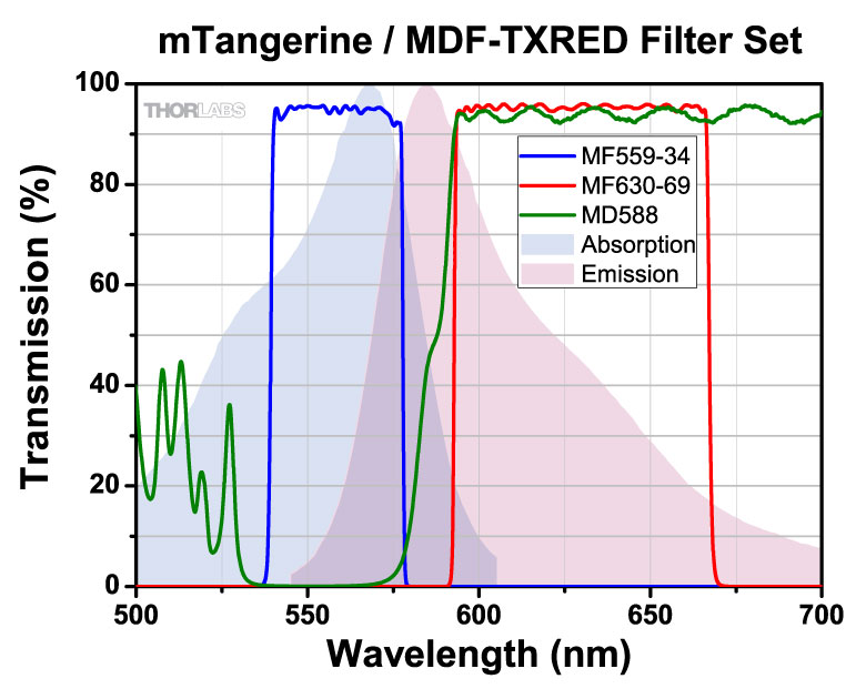
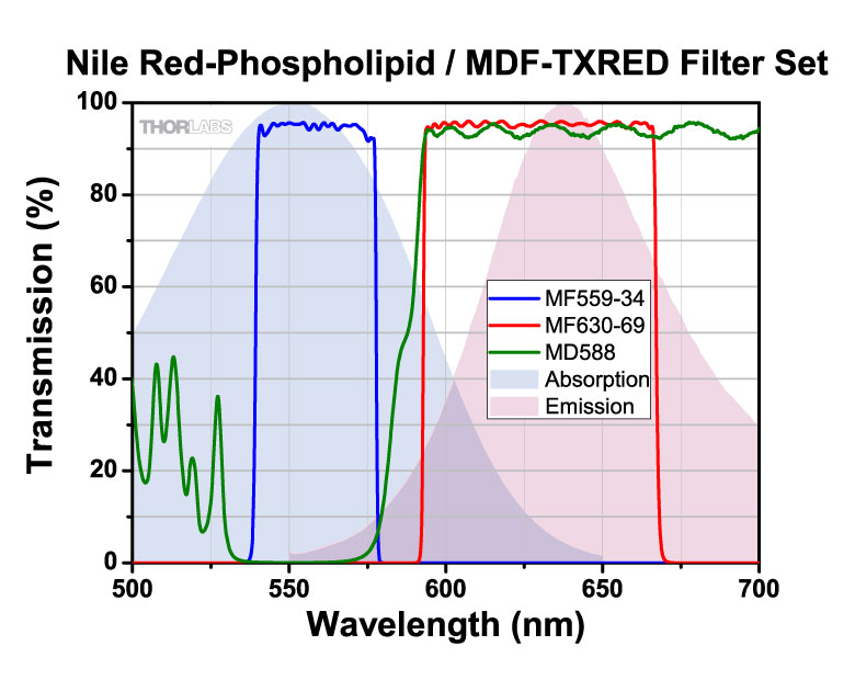
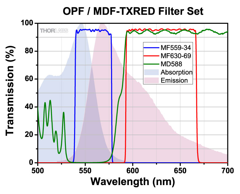
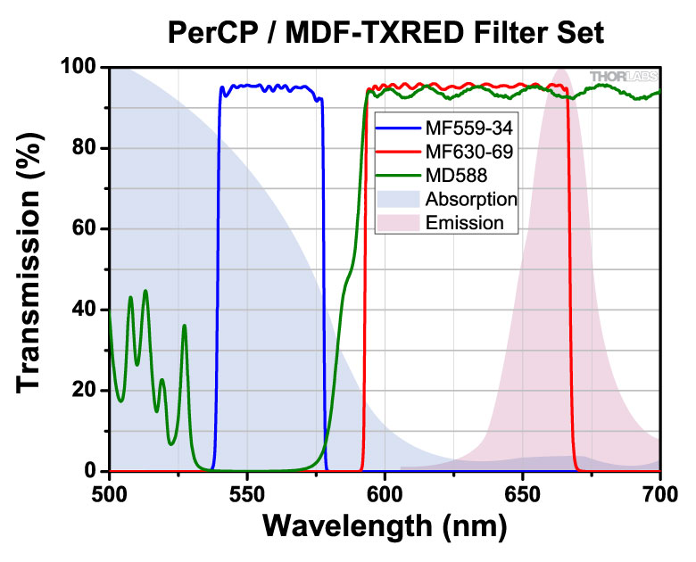
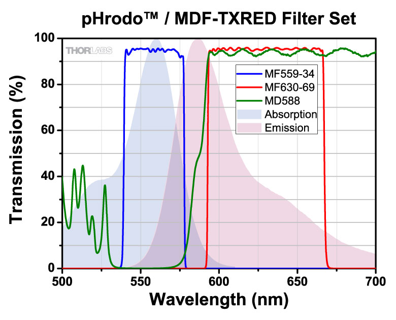
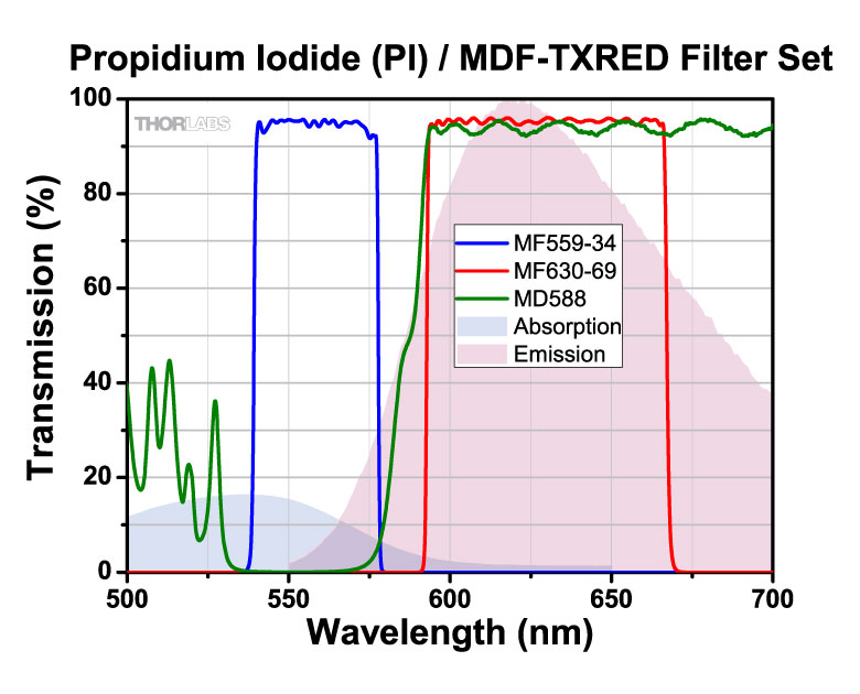
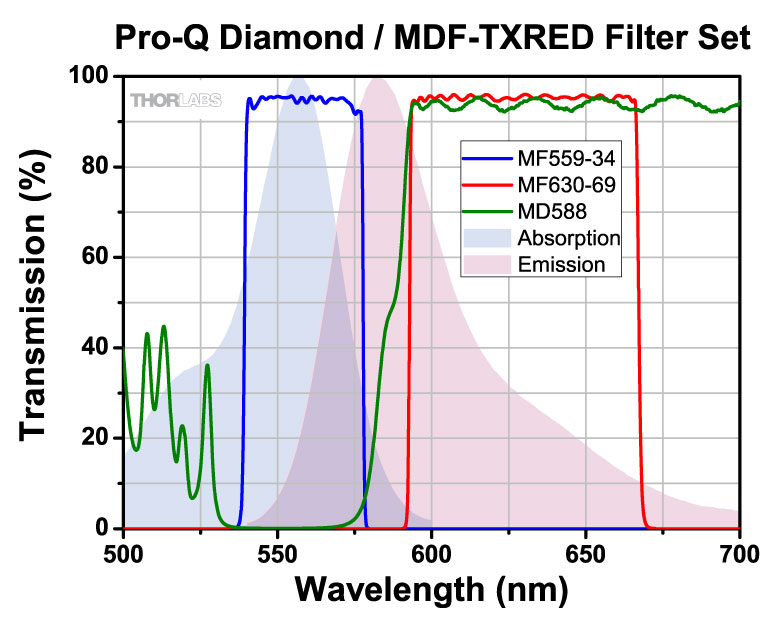
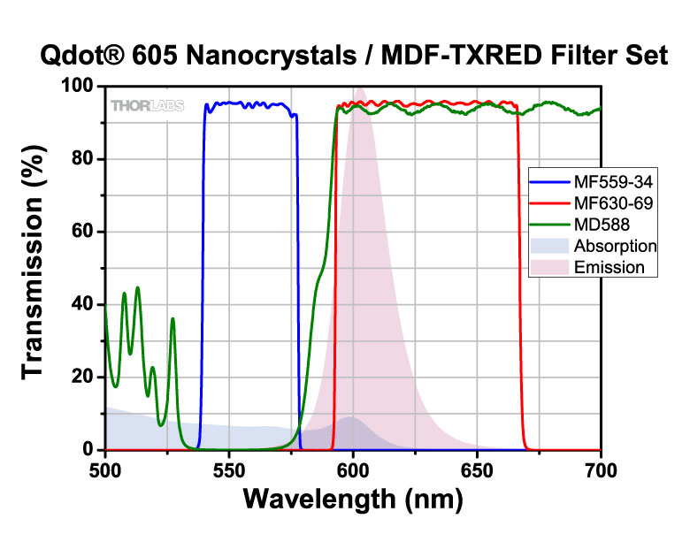
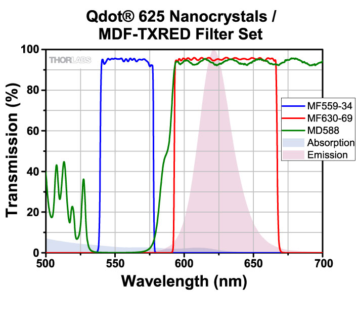
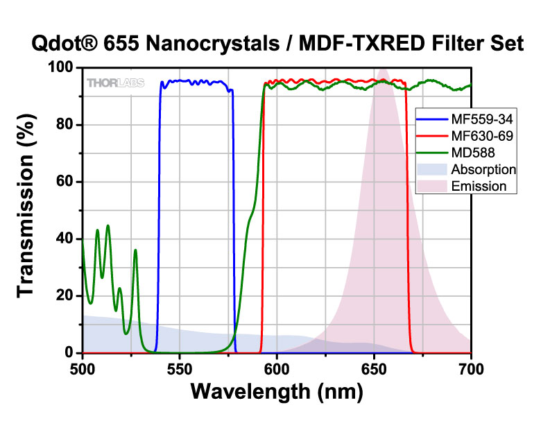
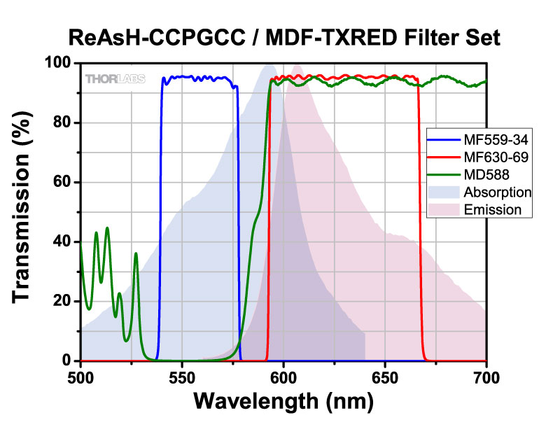
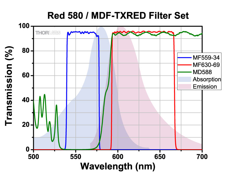
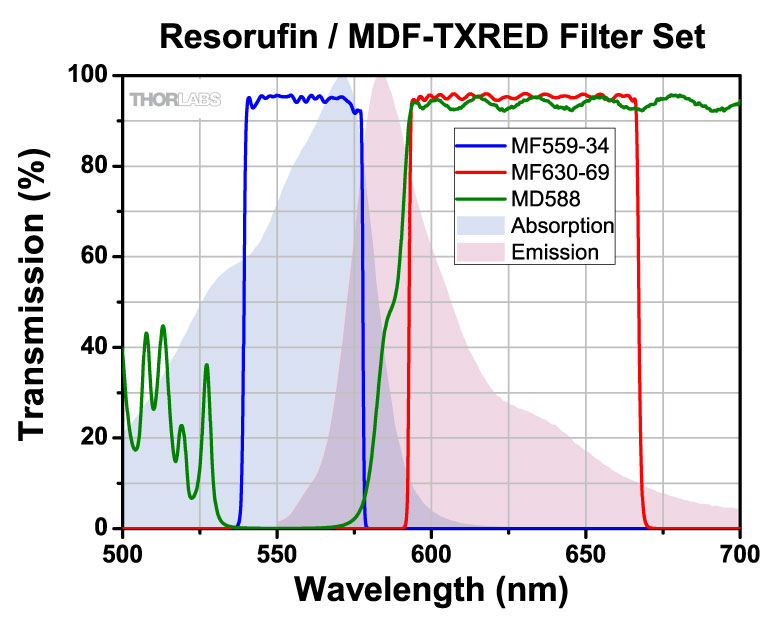
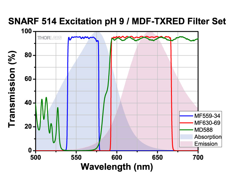
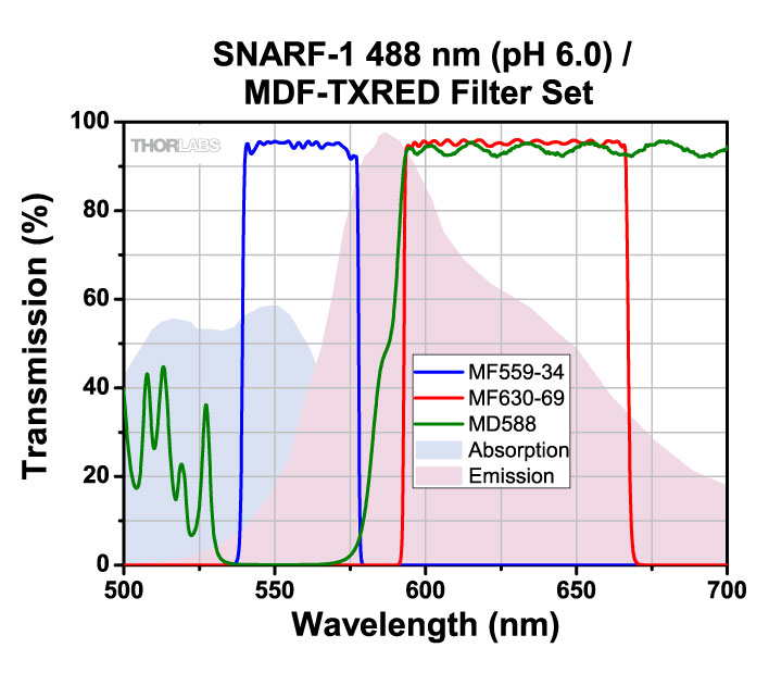
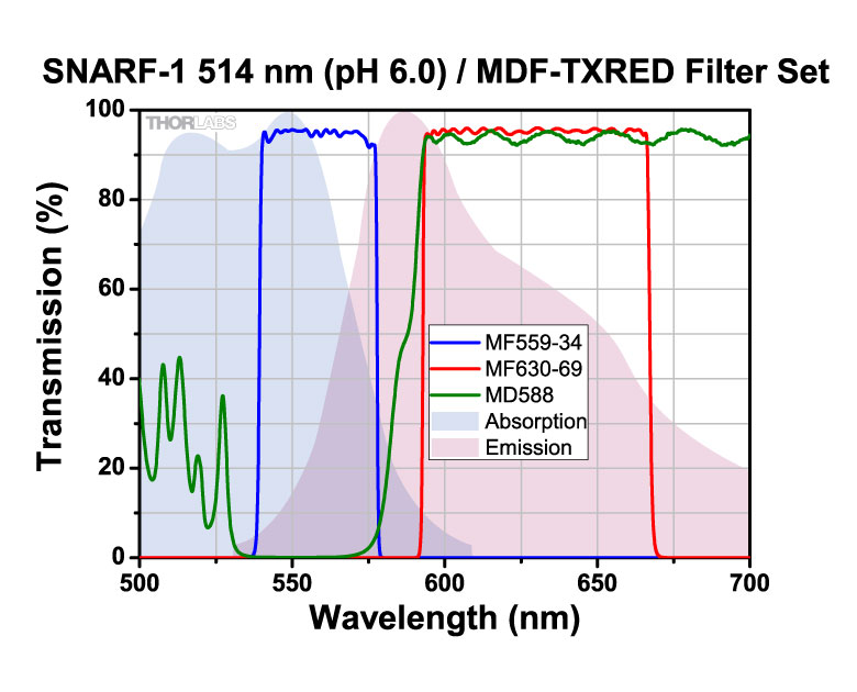
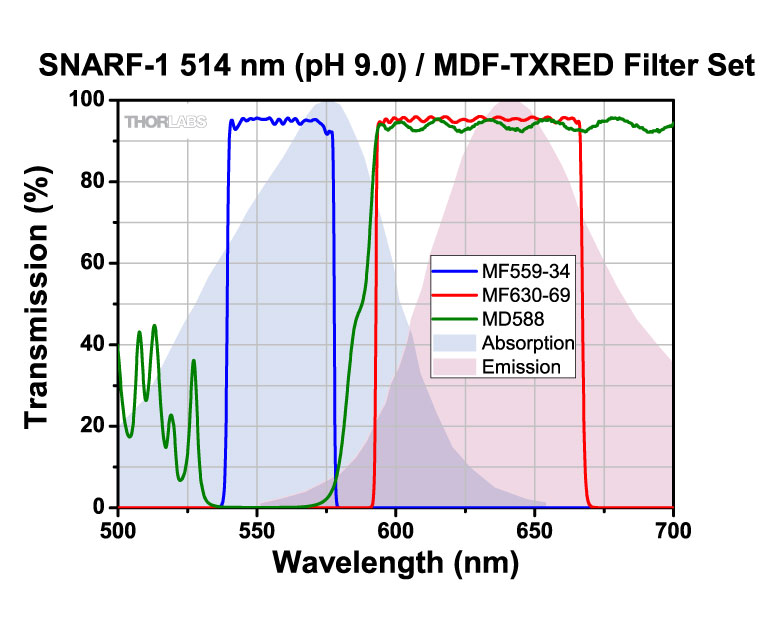
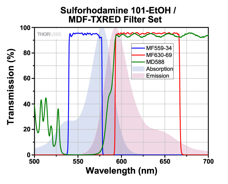
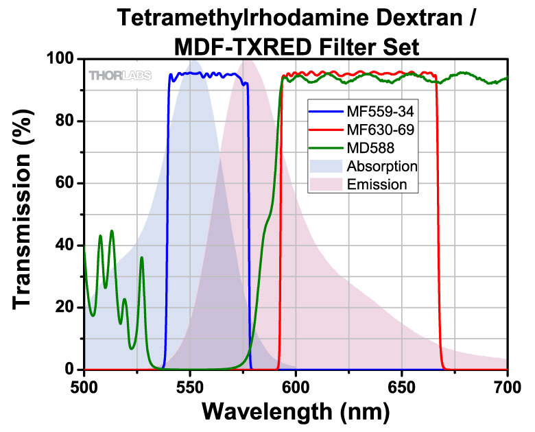
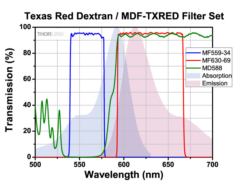
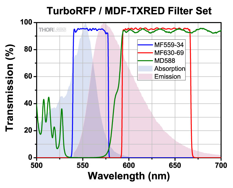
| MDF-TXRED | Texas Red | Excitation | 559 nm | 34 nm | - | - | - | |
| Emission | 630 nm | 69 nm | - | - | - | |||
| Dichroic | - | - | 533 - 580 nm | 595 - 800 nm | Rabs < 2% from 400 to 800 nm |
|||
| MDF-MCHC | mCherry | Excitation | 562 nm | 40 nm | - | - | - | |
| Emission | 641 nm | 75 nm | - | - | - | |||
| Dichroic | - | - | 350 - 585 nm | 601 - 950 nm | - | |||
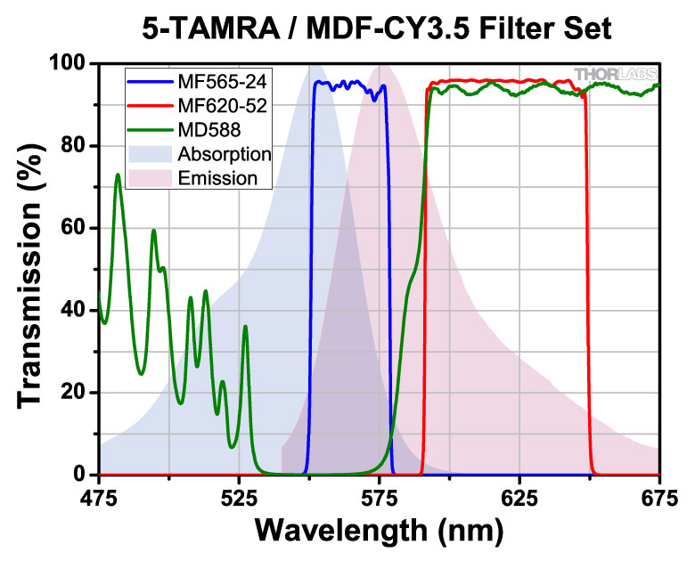
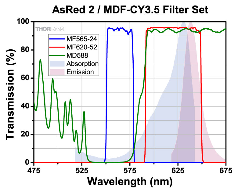
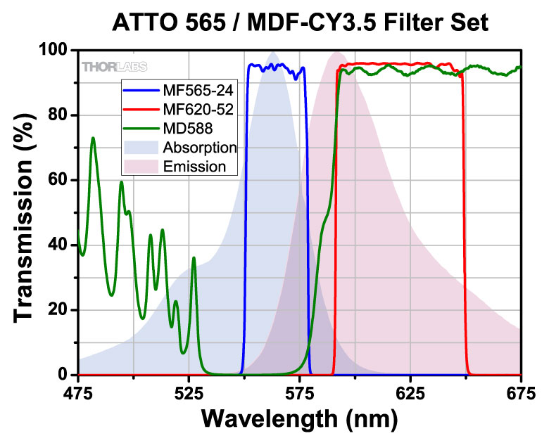
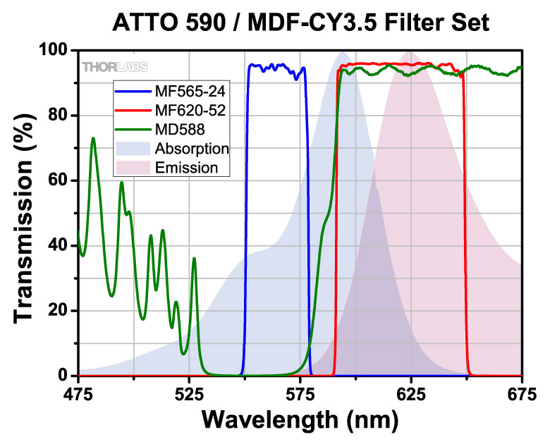
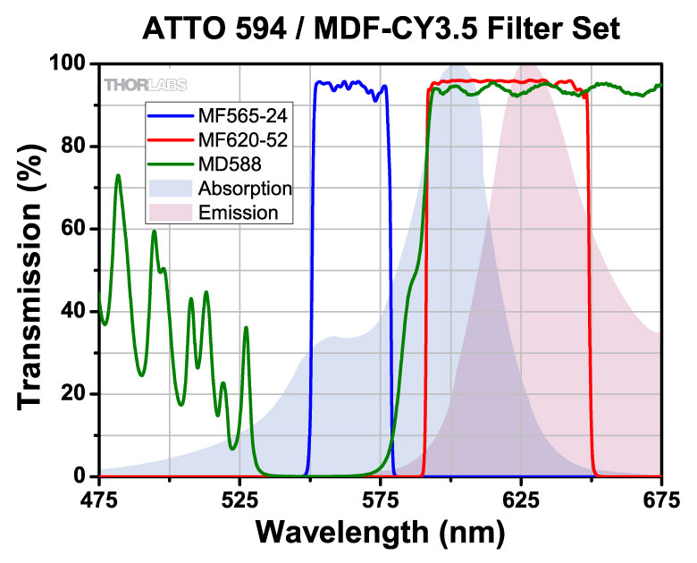
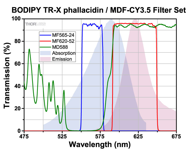
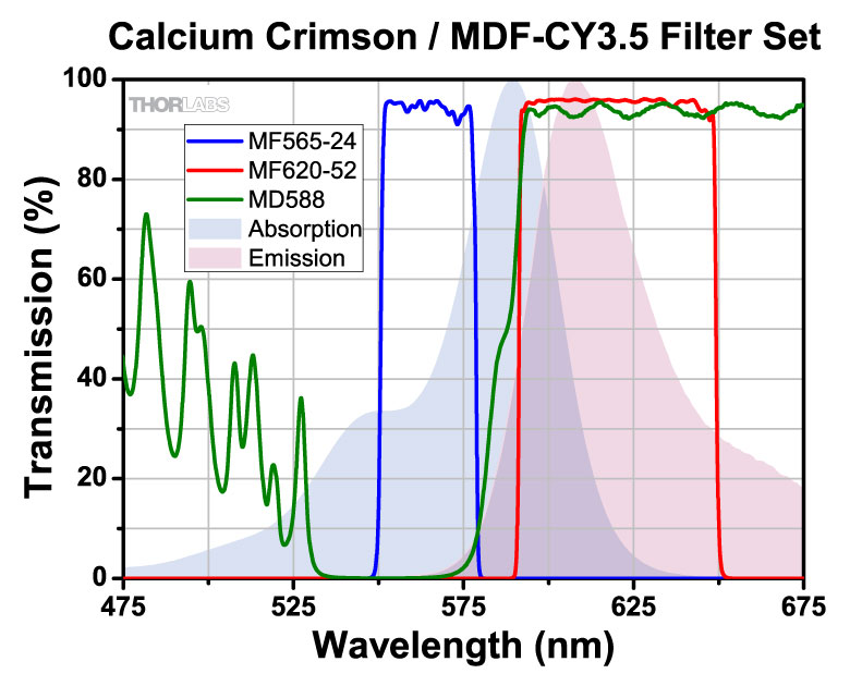
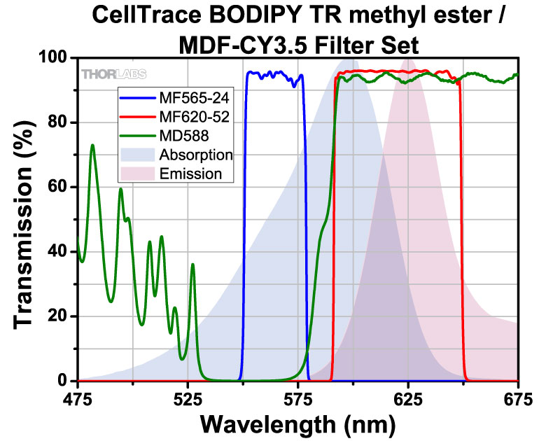
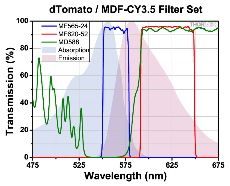
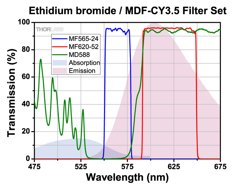
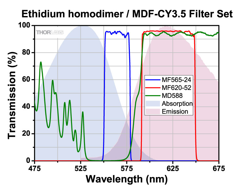
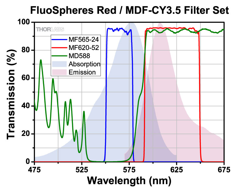
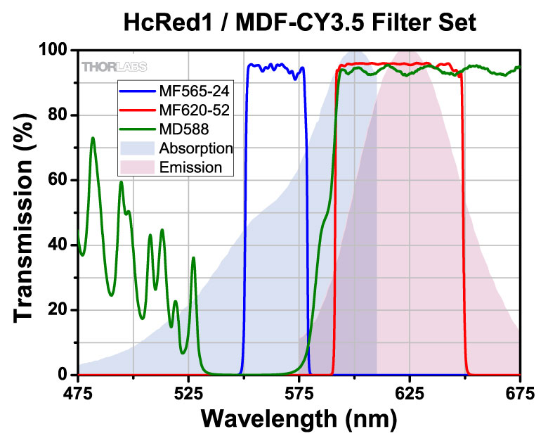
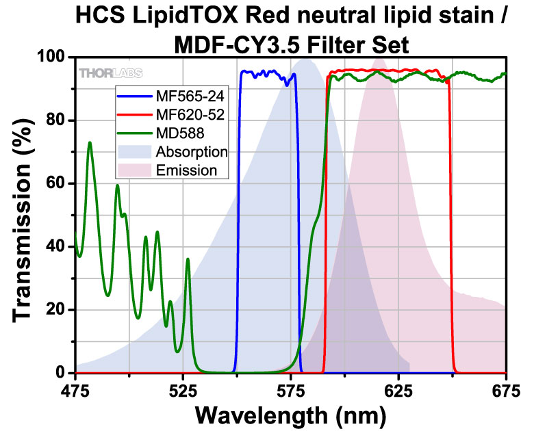
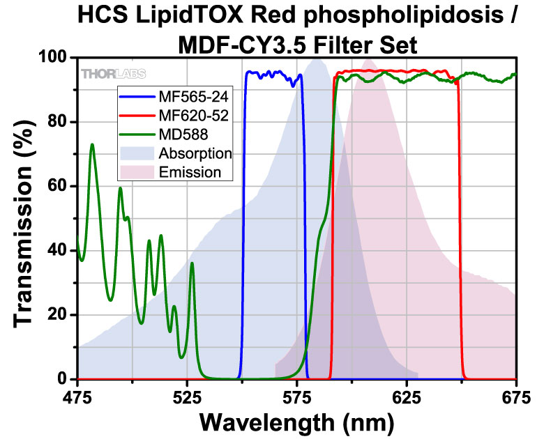
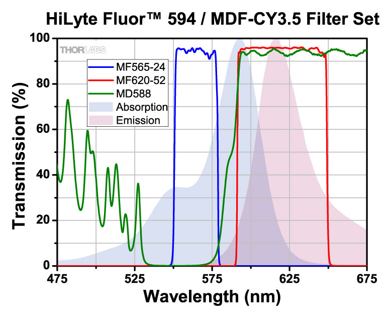
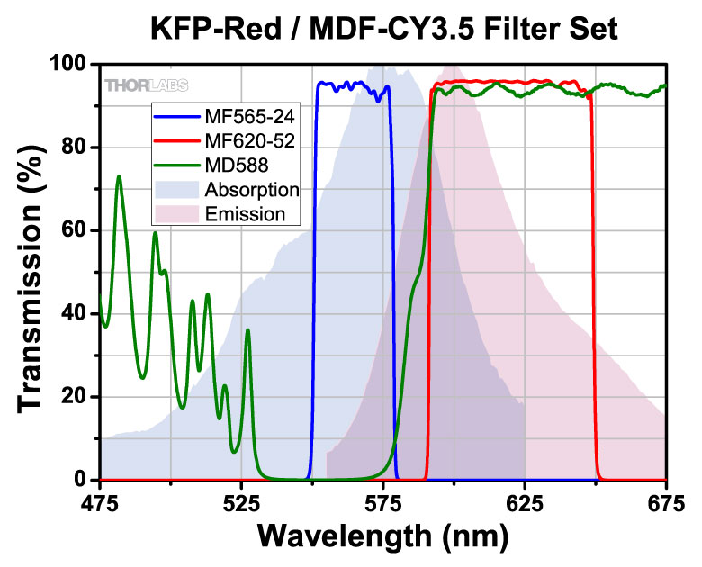
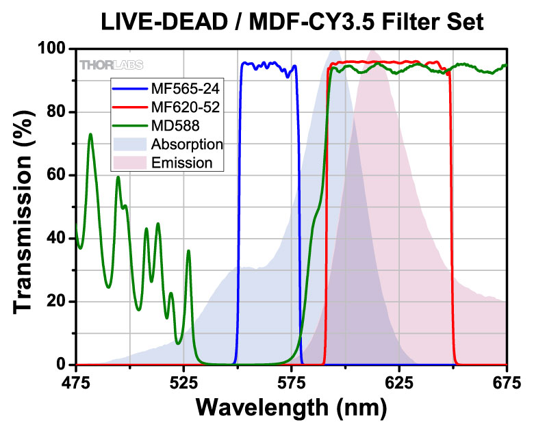
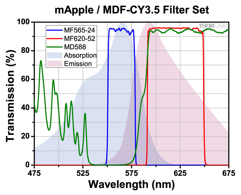
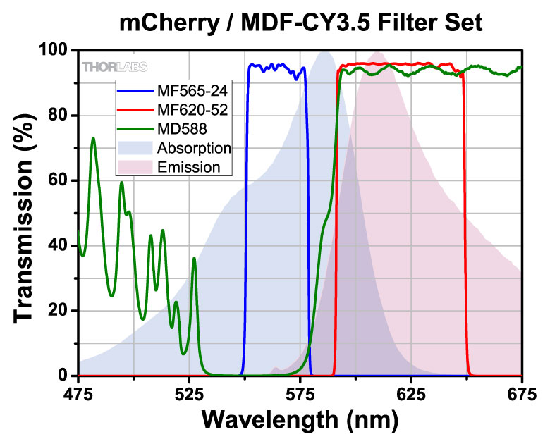
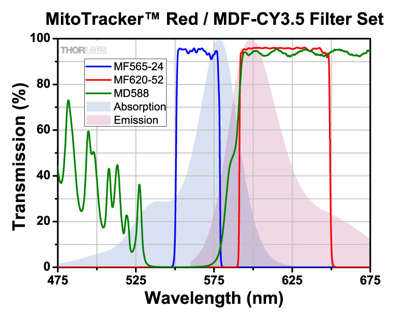
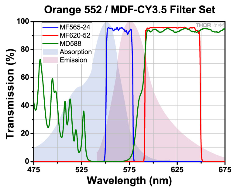
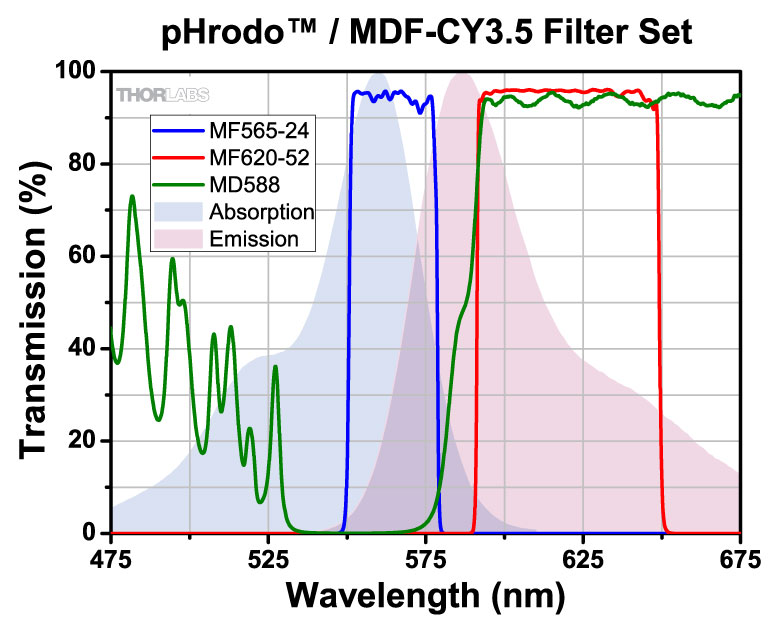
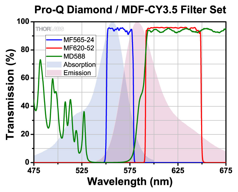
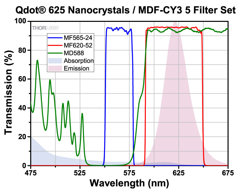
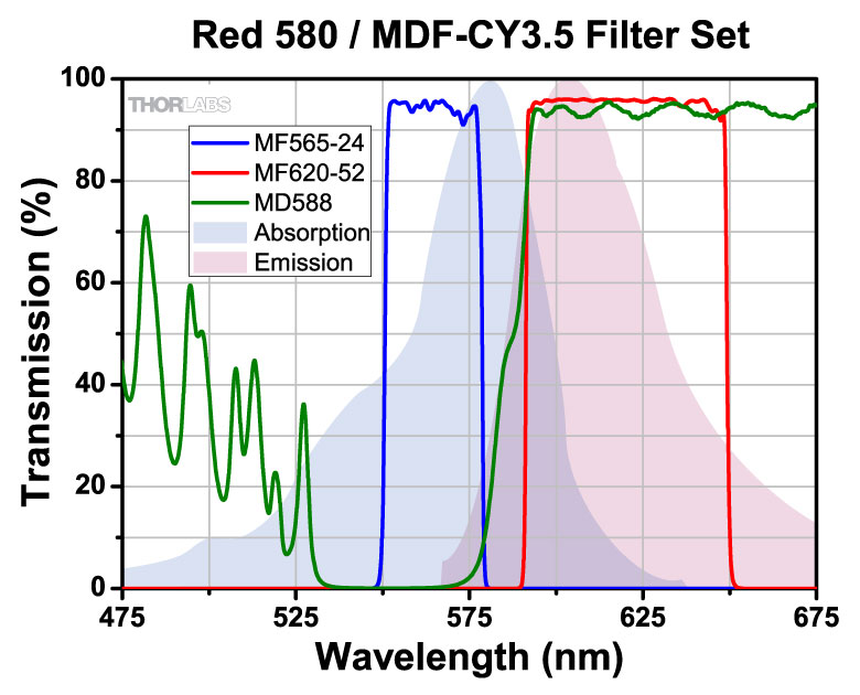
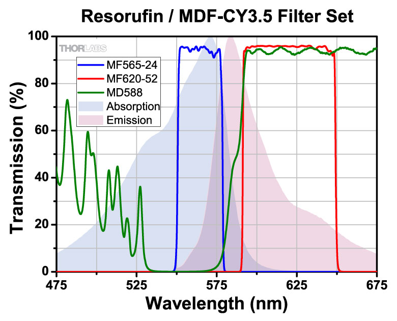
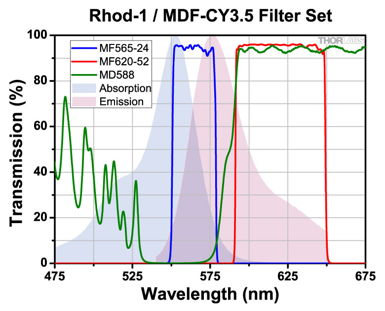
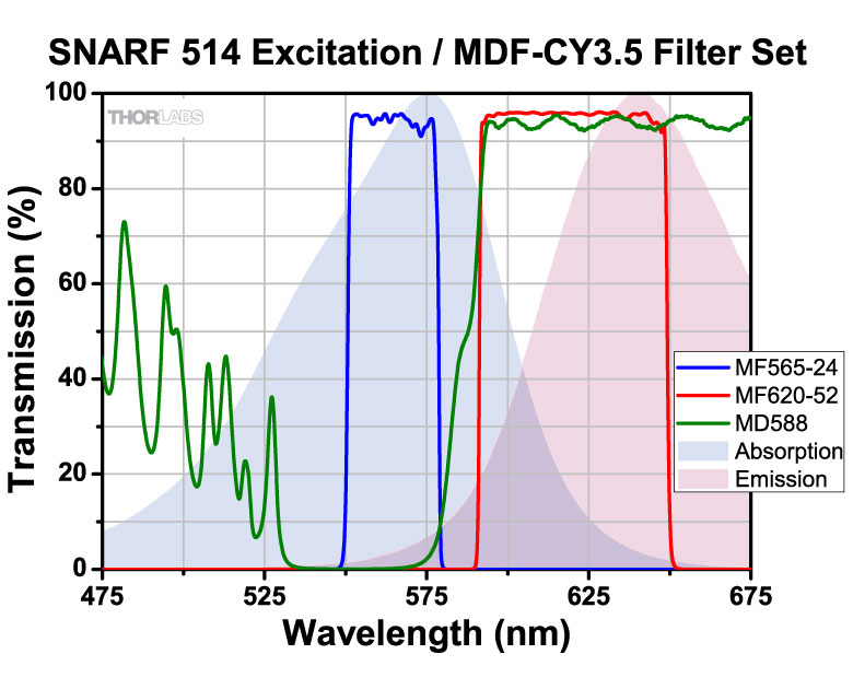
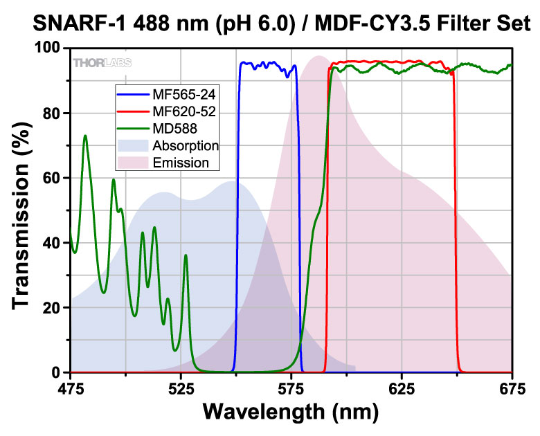
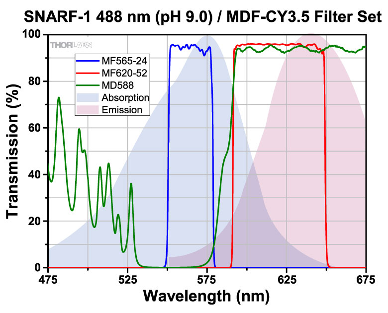
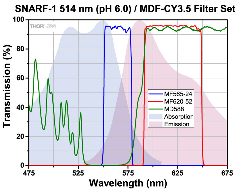
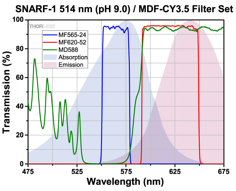
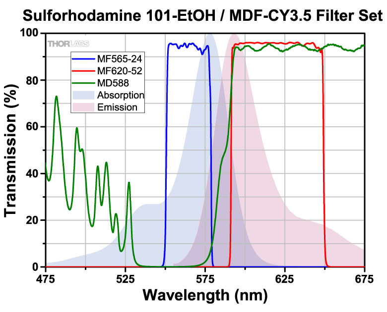
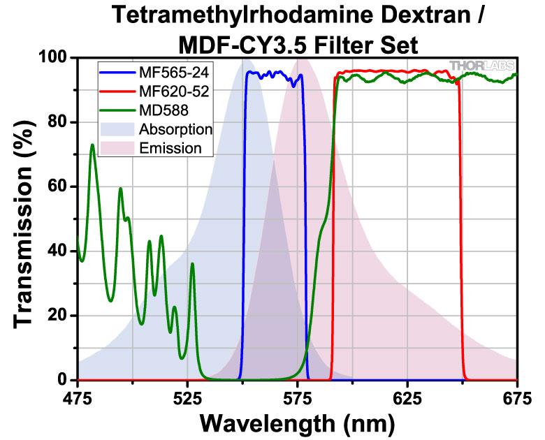
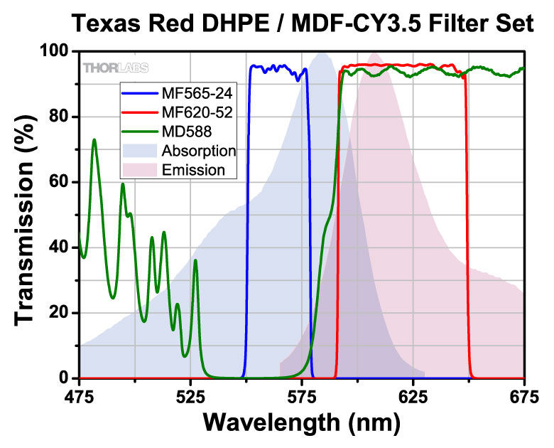
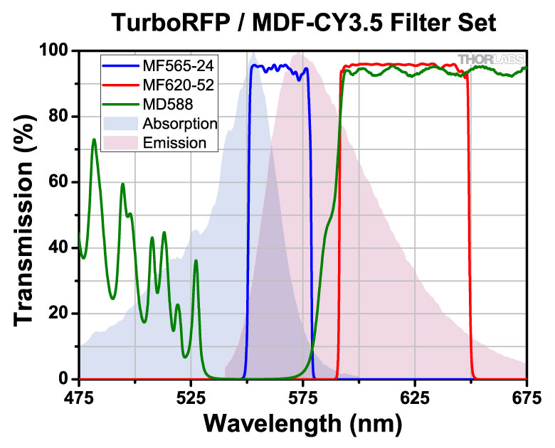
| MDF-CY3.5 | Cyanine (CY3.5) | Excitation | 565 nm | 24 nm | - | - | - | |
| Emission | 620 nm | 52 nm | - | - | - | |||
| Dichroic | - | - | 533 - 580 nm | 595 - 800 nm | Rabs < 2% from 400 to 800 nm |
|||
| MDF-MCHA | mCherry |
Excitation | 578 nm | 21 nm | - | - | - | |
| Emission | 641 nm | 75 nm | - | - | - | |||
| Dichroic | - | - | 350 - 588 nm | 603 - 950 nm | - |
- Select dichroics have an AR coating designed for 45° AOI on the back surface.
- Click on
 for a plot and downloadable data.
 Click to Enlarge
Click to Enlarge
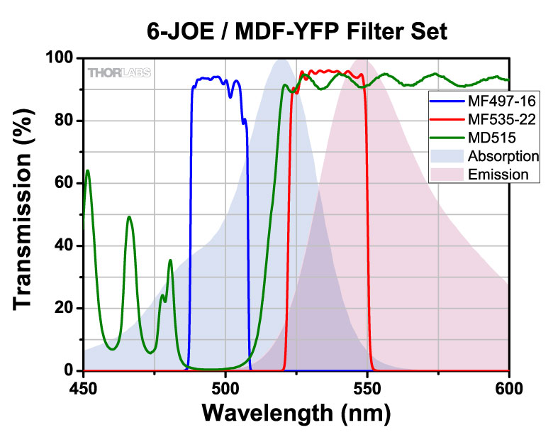
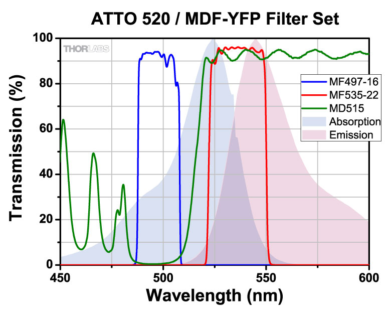
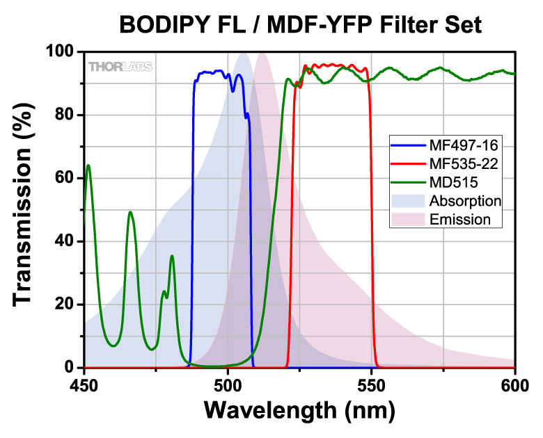
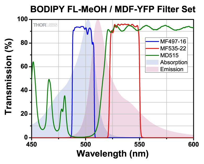
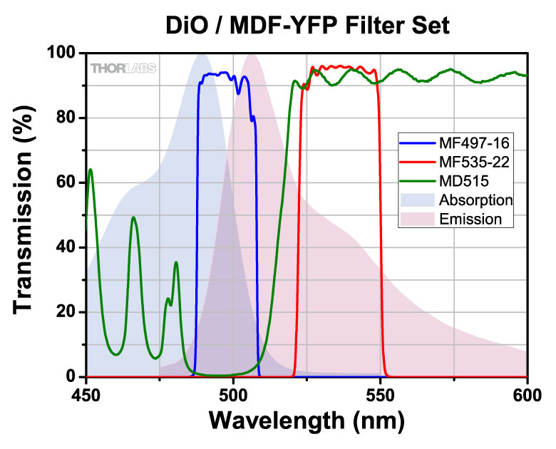
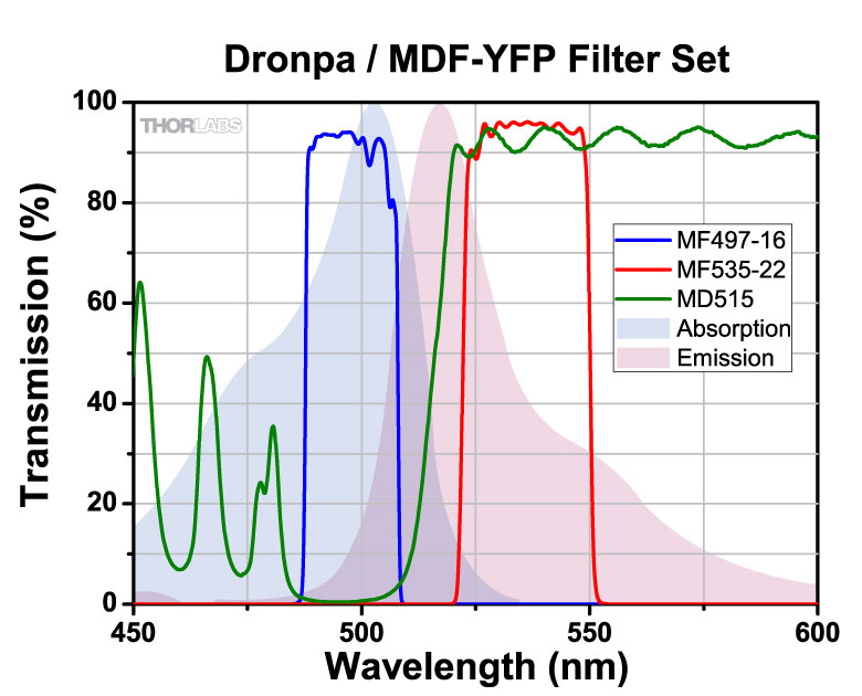
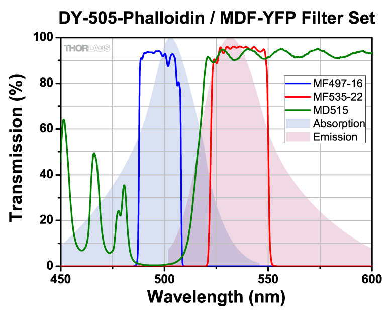
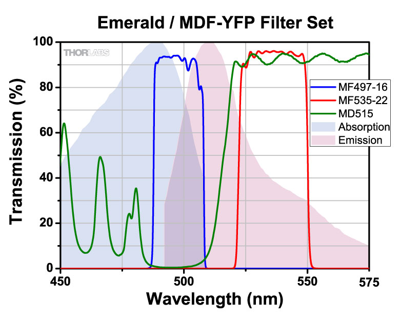
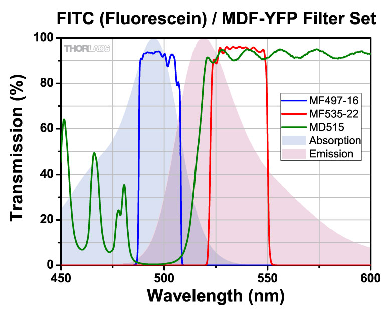
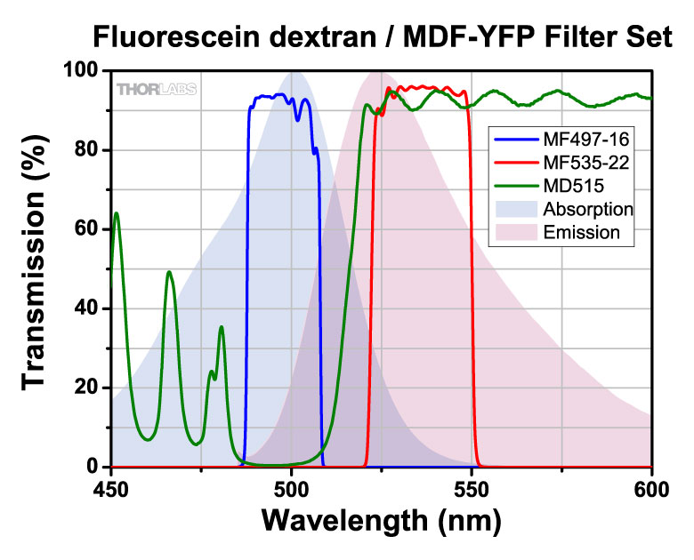
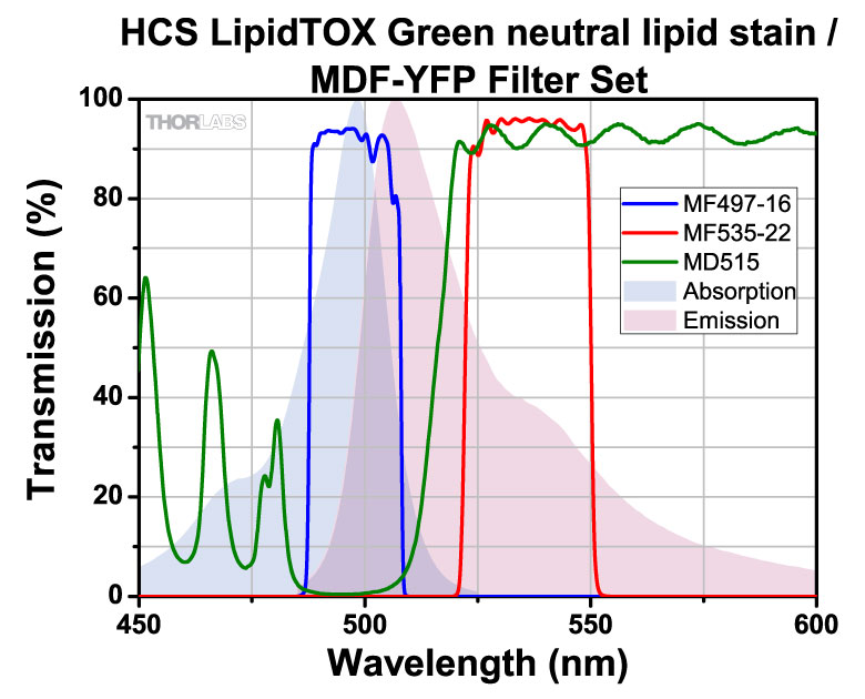
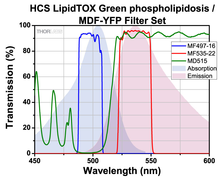
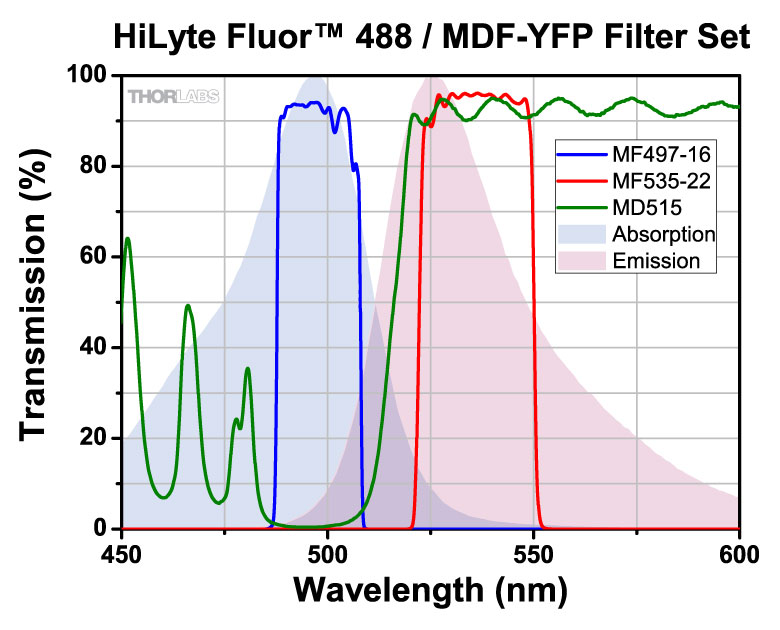
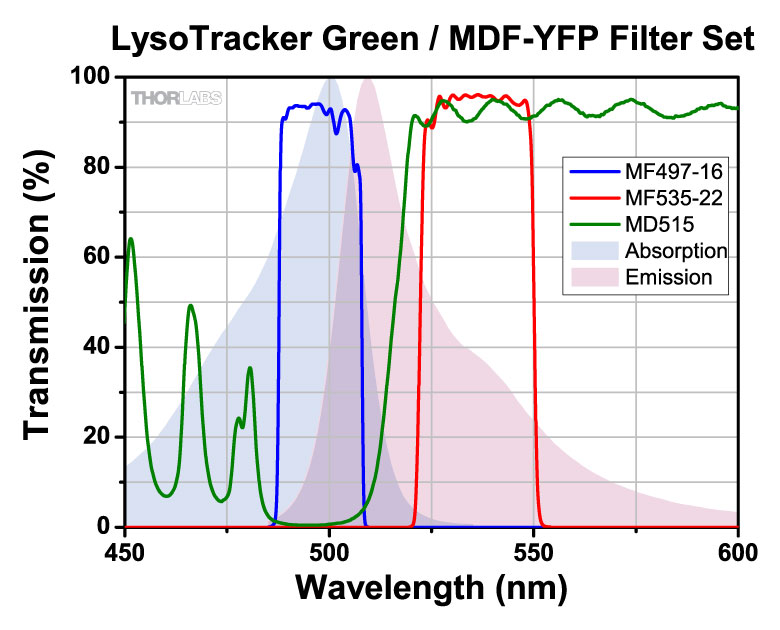
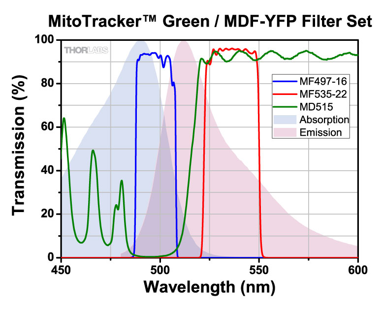
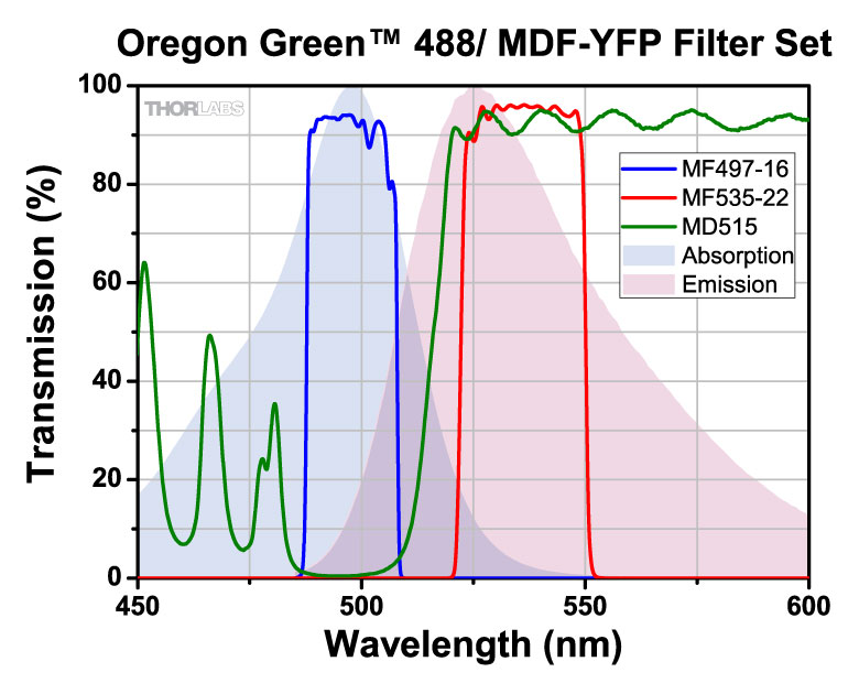
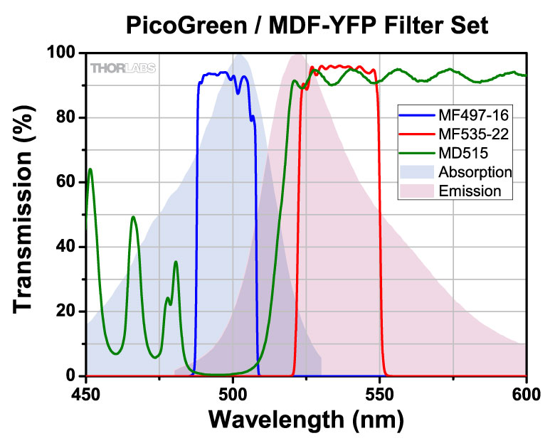
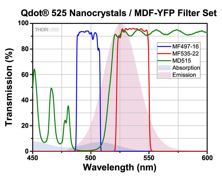
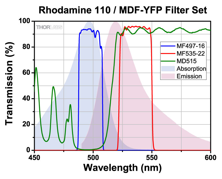
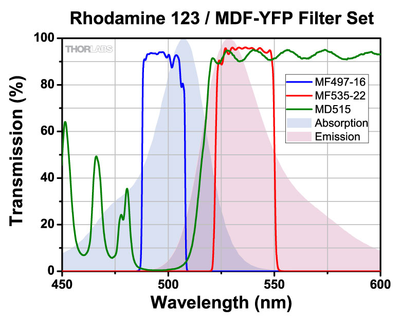
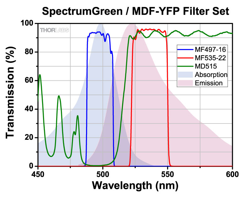
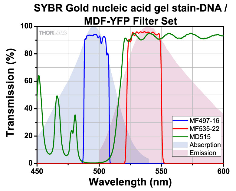
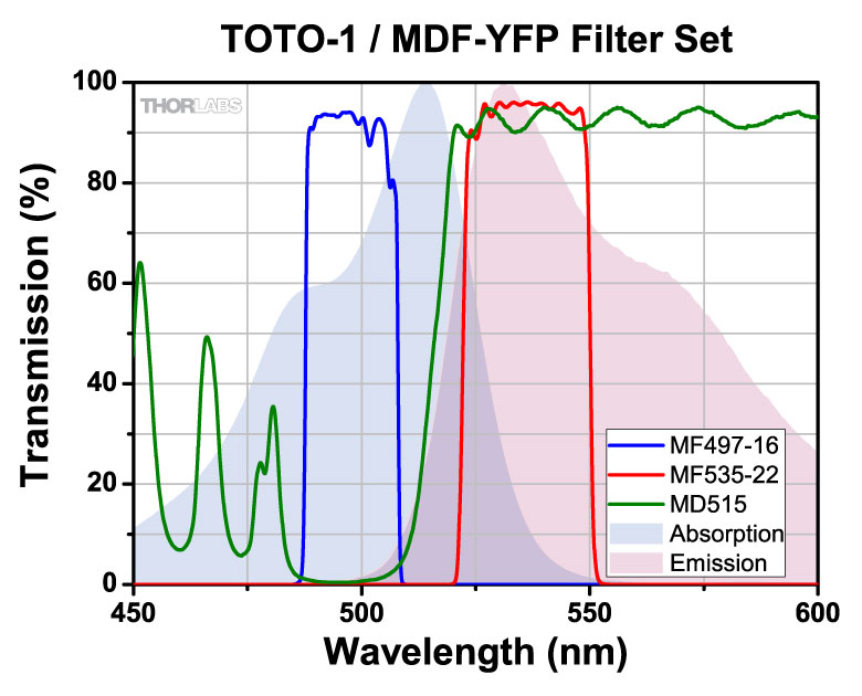
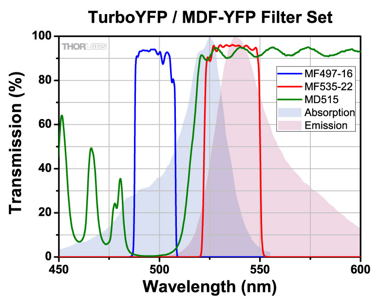
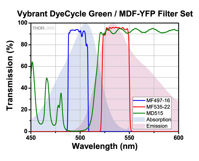
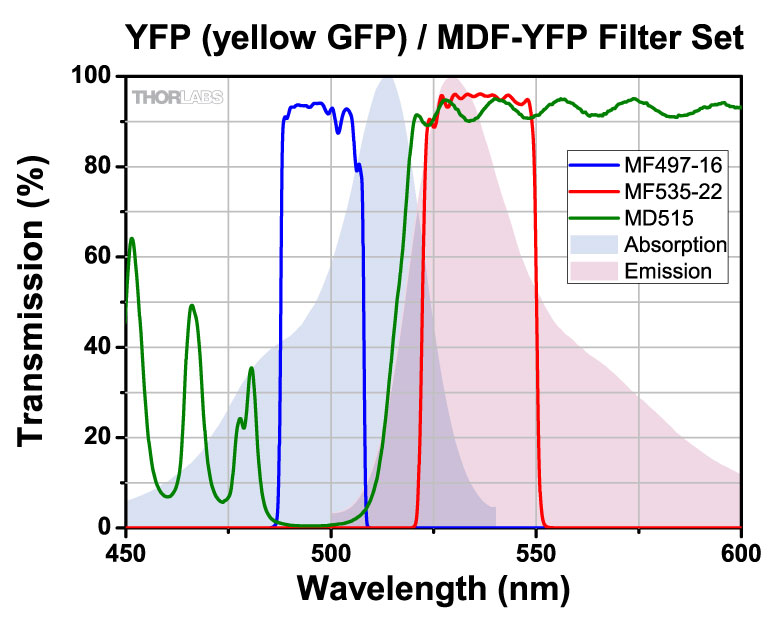
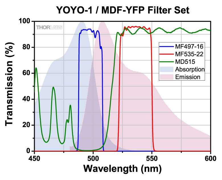
MDF-YFP filter set transmission graph. Note the dichroic mirror (green) reflects light in the excitation wavelength range (blue), and transmits light in the emission wavelength range (green).
Filters for Fluorescence Microscopy
Fluorophores
A fluorophore is a molecule or portion of a molecule that is capable of producing fluorescence. When light of the appropriate frequency necessary to excite a molecule from its ground state to an excited state is present, excitation will occur. However, once in an excited state, the molecule will be unstable. After some short period of time (typically 10-15 to 10-9 s), a photon will be released, thereby enabling the molecule to return to a lower energy state. The emitted radiation will be at a longer wavelength (lower energy) than the absorbed radiation due to the loss of energy through various mechanisms such as vibrations, sound, and thermal energy.
A single fluorophore can be continually excited unless it is destroyed by photobleaching (i.e. the nonreversible destruction of a fluorophore due to photon-induced chemical damage or covalent modification). The average number of excitation and emission cycles that a particular fluorophore can undergo prior to photobleaching depends on its molecular structure and the local environment; some fluorophores bleach quickly after emitting only a few photons while others are far more robust and can undergo thousands or even millions of cycles before bleaching occurs.
Filters for Fluorescence Microscopy
The experimental setup to the right shows the typical filters used for epi-fluorescence microscopy, a form of microscopy in which both the excitation and emission light travel through the microscope objective. By carefully choosing the appropriate filters and mirrors for a given application, the signal-to-noise ratio can be maximized. As shown in the schematic to the right, three types of filters are used to maximize the fluorescence signal while minimizing the unwanted radiation. Each optical element is discussed below.
Excitation Filter
The excitation filter only allows a narrow band of wavelengths to pass through it, around the peak fluorophore excitation wavelength. For example, as shown in the graph to the right, the bandpass region corresponding to greater than 90% transmission for the Yellow Fluorescent Protein (YFP) Excitation Filter (MF497-16) is 489 - 505 nm; incident radiation outside of this range is either partially (for regions near the transmission region) or totally (for regions further from the bandpass region) blocked by the filter.
Dichroic Mirror
Dichroic mirrors are designed to reflect light whose wavelength is below a specific value (i.e. the cutoff wavelength) while permitting all other wavelengths to pass through it unaltered. In a microscope, the dichroic mirror directs the proper wavelength range to the sample as well as to the image plane. The cutoff wavelength value associated with each mirror indicates the wavelength that corresponds to 50% transmission. For example, as shown in the graph to the right, the cutoff wavelength for the Yellow Fluorescent Protein (YFP) Dichroic Mirror (MD515) is ~515 nm. The Specs tab provides information on wavelength ranges corresponding to ≥ 90% average reflectance and transmission for each type of dichroic mirror.
By placing one of these mirrors into the experimental setup at 45° with respect to the incident radiation, the excitation radiation (shown in blue in the above right schematic) is reflected off of the surface of the dichroic mirror and directed towards the sample and microscope objective, while the fluorescence emanating from the sample (shown in red in the above right schematic) passes through the mirror to the detection system.
Although dichroic mirrors play a crucial role in fluorescence microscopy, they are not perfect when it comes to blocking unwanted light; typically, ~90% of the light at wavelengths below the cutoff wavelength value are reflected and ~90% of the light at wavelengths above this value are transmitted by the dichroic mirror. Hence, some of the excitation light can be transmitted through the dichroic mirror along with the longer wavelength fluorescence emitted by the sample. To prevent this unwanted light from reaching the detection system, an emission filter is used in addition to the dichroic mirror.
Emission Filter
An emission filter serves the purpose of allowing the desirable fluorescence from the sample to reach the detector while blocking unwanted traces of excitation light. Like the excitation filter, this filter only allows a narrow band of wavelengths to pass through it, around the peak fluorophore emission wavelength. For example, as shown in the graph to the right, the bandpass region corresponding to greater than 90% transmission for the Yellow Fluorescent Protein (YFP) Emission Filter (MF535-22) is 524 - 546 nm; incident radiation outside of this range is either partially (for regions near the transmission region) or totally (for regions further from the bandpass region) blocked by the filter.
| Keya | |
|---|---|
 |
Acceptable - Actual performance depends on individual experimental conditions. |
|
Compatible - Ideal, or nearly ideal, performance under most experimental conditions. |
 |
Optimized - Optimal performance under all experimental conditions. |
a. Absorption and emission spectra are unavailable if any  is red.
The table below displays all of the fluorophores that are compatible with our filter sets. The filter set item numbers are listed across the top row and the fluorophores are listed down the first column. Scroll through the table to view fluorophore compatibility with our filter sets.
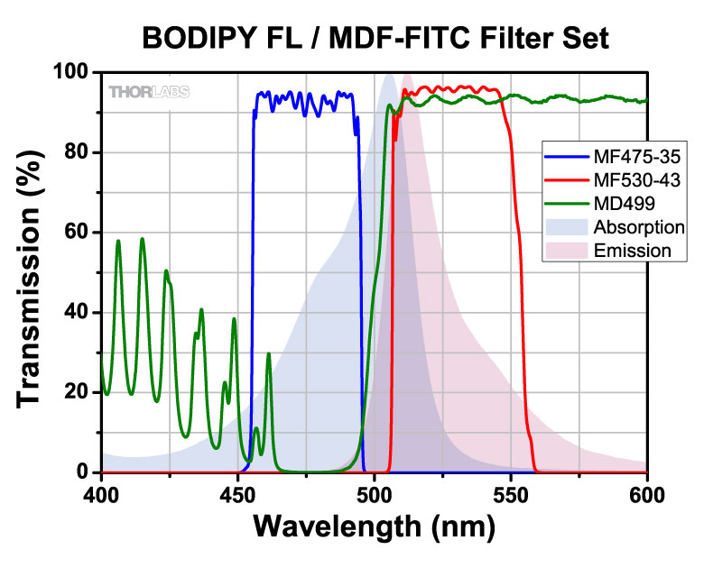
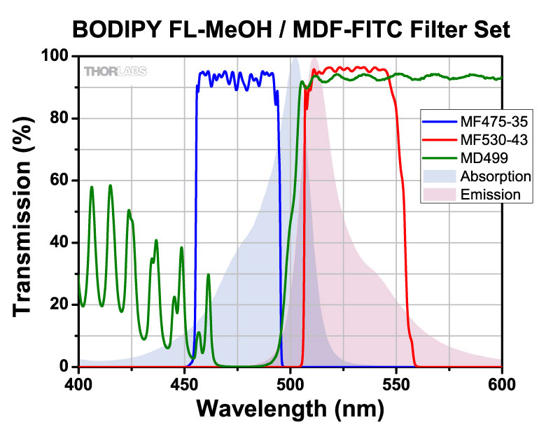
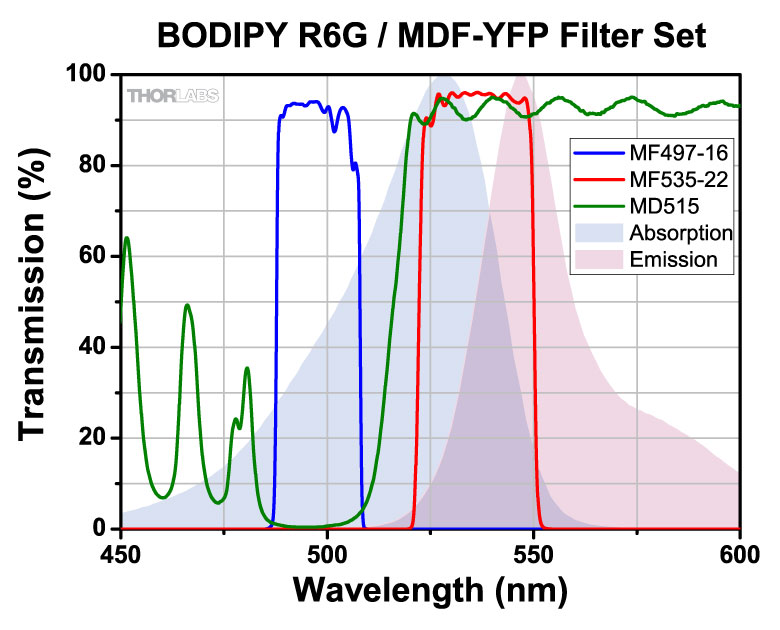
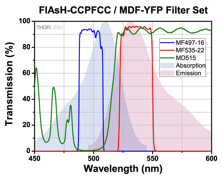
Click on the below to view the filter set transmission with the absorption and emission spectra of the fluorophore. The key to the right details the meaning of all check marks in the table below. Please note that absorption and emission spectra are unavailable if any is red.
| 1,8-ANS (372 nm, 477 nm) | ✓ | ||||||||||||
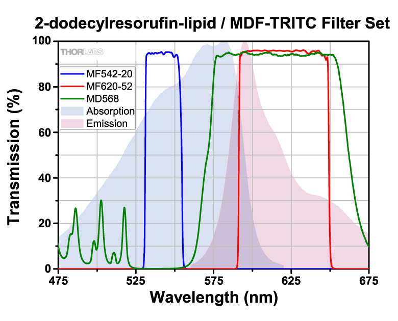
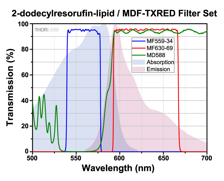
| 2-dodecylresorufin-lipid (582 nm, 595 nm) | ✓ | ✓ | ✓✓ | ✓ | ✓✓ | ✓ | |||||||
| 5-carboxy-2,7-dichlorofluorescein (500 nm, 525 nm) | ✓ | ✓ | ✓✓ | ||||||||||
| 5-carboxynapthofluorescein (pH 10) (555 nm, 615 nm) | ✓ | ✓ | |||||||||||
| 5-FAM (5-carboxyfluorescein) (492 nm, 518 nm) | ✓✓ | ✓✓ | ✓ | ✓✓ | |||||||||
| 5-ROX (carboxy-X-rhodamine) (578 nm, 604 nm) | ✓ | ✓ | ✓✓✓ | ✓✓ | ✓✓ | ✓ | |||||||
| 5-TAMRA (5-carboxytetra- methylrhodamine, pH 7.0) (542 nm, 568 nm) | ✓ | ✓ | ✓ | ✓ | ✓ | ||||||||
| 6-carboxyrhodamine 6G (525 nm, 555 nm) | ✓ | ✓ | |||||||||||
| 6-JOE (520 nm, 548 nm) | ✓ | ✓ | |||||||||||
| 7-AAD (548 nm, 648 nm) | ✓ | ✓ | ✓ | ✓ | ✓ | ✓ | |||||||
| Acridine Orange (502 nm, 526 nm) | ✓ | ✓ | ✓ | ||||||||||
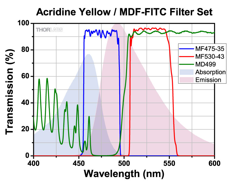
| Acridine Yellow (470 nm , 550 nm) | ✓ | ✓✓ | ✓ | ✓ | |||||||||
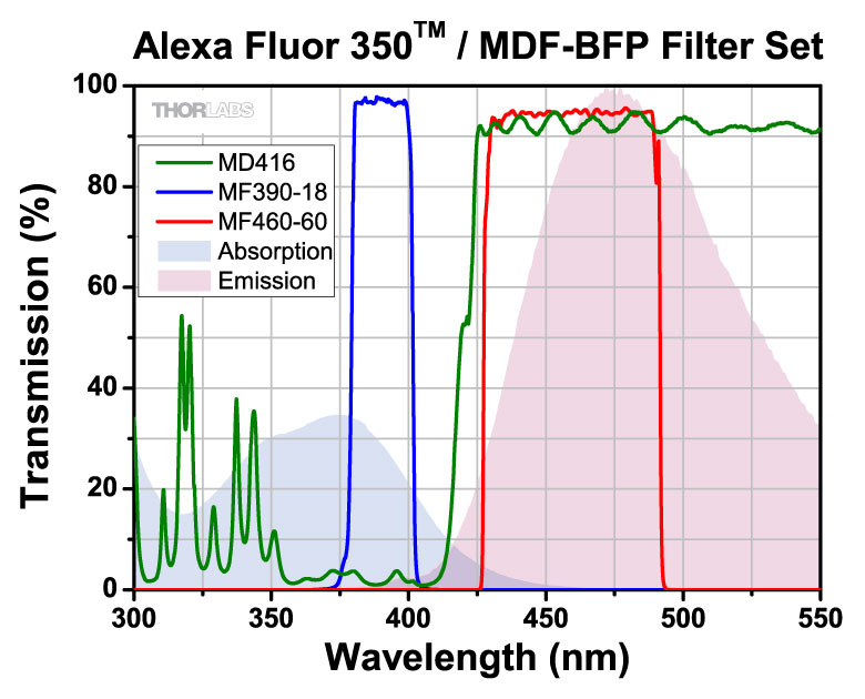
| Alexa Fluor 350™ (343 nm, 441 nm) | ✓✓ | ||||||||||||
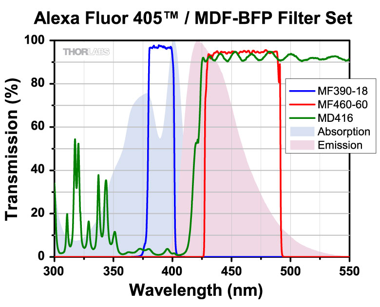
| Alexa Fluor 405™ (401 nm, 422 nm) | ✓ | ||||||||||||
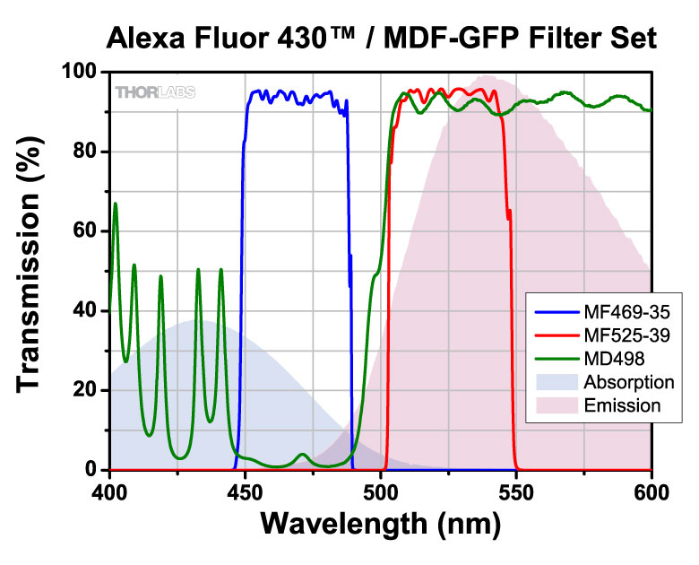
| Alexa Fluor 430™ (431 nm , 541 nm) | ✓ | ✓ | ✓ | ||||||||||
| Alexa Fluor 488™ (499 nm, 520 nm) | ✓ | ✓✓✓ | ✓✓ | ||||||||||
| Alexa Fluor 500™ (503 nm, 525 nm) | ✓ | ✓ | ✓✓ | ||||||||||
| Alexa Fluor 514™ (518 nm, 543 nm) | ✓ | ||||||||||||
| Alexa Fluor 546™ (556 nm, 572 nm) | ✓✓✓ | ✓ | |||||||||||
| Alexa Fluor 568™ (579 nm, 603 nm) | ✓ | ✓ | ✓✓✓ | ✓✓ | ✓✓ | ✓ | |||||||
| Alexa Fluor 594™ (590 nm, 618 nm) | ✓ | ✓ | ✓ | ✓ | |||||||||
| AMCA (Aminomethylcoumarin) (350 nm, 488 nm) | ✓✓ | ||||||||||||
| AmCyan1 (458 nm, 489 nm) | ✓✓✓ | ✓✓ | ✓ | ✓ | |||||||||
| Amplex UltraRed peroxidation product -pH 7.5 (568 nm, 581 nm) | ✓ | ✓ | ✓ | ✓ | ✓ | ✓ | |||||||
| Aqua 431 (430 nm,478 nm) | ✓✓ | ✓ | |||||||||||
| AsRed 2 (576 nm, 592 nm) | ✓ | ✓ | ✓ | ✓ | ✓ | ✓ | |||||||
| ATTO 390 (392 nm, 477 nm) | ✓✓ | ||||||||||||
| ATTO 425 (436 nm, 484 nm) | ✓✓ | ✓✓ | |||||||||||
| ATTO 465 (453 nm, 507 nm) | ✓ | ✓✓ | ✓✓ | ✓✓ | ✓ | ||||||||
| ATTO 488 (500 nm, 525 nm) | ✓ | ✓ | ✓ | ✓✓ | |||||||||
| ATTO 495 (495 nm, 527 nm) | ✓ | ✓ | ✓✓ | ✓ | ✓✓ | ||||||||
| ATTO 520 (516 nm, 538 nm) | ✓ | ✓ | |||||||||||
| ATTO 550 (553 nm, 576 nm) | ✓ | ✓ | ✓ | ✓ | |||||||||
| ATTO 565 (563 nm, 592 nm) | ✓ | ✓ | ✓✓ | ✓ | ✓✓ | ||||||||
| ATTO 590 (594 nm, 624 nm) | ✓ | ✓ | ✓ | ✓ | |||||||||
| ATTO 594 (601 nm, 624 nm) | ✓ | ||||||||||||
| BCECF (pH 5.5) (481 nm, 518 nm) | ✓ | ✓✓ | ✓✓ | ✓ | ✓ | ||||||||
| BCECF (pH 9.0) (502 nm, 528 nm) | ✓ | ✓ | ✓✓ | ||||||||||
| BD Horizon V450 (406 nm, 449 nm) | ✓✓ | ||||||||||||
| BD Horizon V500 (410 nm, 500 nm) | ✓ | ✓ | ✓ | ||||||||||
| BFP (EBFP) (380 nm, 440 nm) | ✓✓ | ||||||||||||
| BOBO™-1 (461 nm, 484 nm) | ✓✓✓ | ✓✓ | ✓ | ✓ | |||||||||
| BOBO™-3 (570 nm, 605 nm) | ✓ | ✓ | ✓✓ | ✓ | ✓✓ | ✓ | |||||||
| BODIPY FL (505 nm, 512 nm) | ✓ | ✓ | ✓ | ✓ | |||||||||
| BODIPY FL-MeOH (502 nm, 511 nm) | ✓ | ✓ | ✓ | ||||||||||
| BODIPY R6G (528 nm, 547 nm) | ✓ | ✓ | |||||||||||
| BODIPY TR-X phallacidin (590 nm, 621 nm) | ✓ | ✓ | ✓ | ✓ | ✓ | ||||||||
| Calcein (494 nm, 514 nm) | ✓ | ✓✓ | ✓ | ✓ | |||||||||
| Calcium Crimson (589 nm, 609 nm) | ✓ | ✓ | |||||||||||
| Calcium Green-1 (507 nm, 529 nm) | ✓ | ✓✓✓ | |||||||||||
| Calcium Orange (589 nm, 609 nm) | ✓ | ✓ | ✓ | ✓ | ✓ | ||||||||
| Carboxynaphthofluorescein (599 nm, 674 nm) | ✓ | ✓ | ✓ | ||||||||||
| Cascade Blue™ (401 nm, 419 nm) | ✓ | ||||||||||||
| CellTrace BODIPY TR methyl ester (598 nm, 625 nm) | ✓ | ✓ | ✓ | ✓ | |||||||||
| CellTrace calcein violet (400 nm, 452 nm) | ✓✓ | ||||||||||||
| CellTracker Red CMTPX (586 nm, 614 nm) | ✓ | ✓ | ✓ | ✓ | ✓ | ||||||||
| CellTracker Violet BMQC+GSH (406 nm, 526 nm) | ✓ | ✓ | |||||||||||
| Cerulean (434 nm, 473 nm) | ✓✓✓ | ✓ | ✓ | ||||||||||
| CFP (ECFP) (433 nm, 475 nm) | ✓✓✓ | ✓ | ✓ | ✓ | |||||||||
| CFP2 (490 nm, 510 nm) | ✓ | ✓✓ | ✓✓ | ✓ | ✓ | ||||||||
| Cy2™ (492 nm, 507 nm) | ✓ | ✓✓✓ | ✓ | ||||||||||
| Cy3.5™ (578 nm, 591 nm) | ✓ | ✓ | ✓✓ | ✓ | ✓✓✓ | ✓✓ | |||||||
| CyQUANT GR-DNA (502 nm, 523 nm) | ✓ | ✓ | ✓ | ✓✓ | |||||||||
| DAF-FM-NO (495 nm, 519 nm) | ✓ | ✓✓ | ✓ | ✓✓ | |||||||||
| DAPI (359 nm, 461 nm) | ✓✓✓ | ||||||||||||
| DDAO (648 nm, 657 nm) | ✓ | ✓ | ✓ | ||||||||||
| DEAC (432 nm, 472 nm) | ✓ | ✓✓ | ✓ | ||||||||||
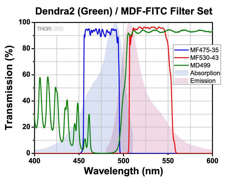
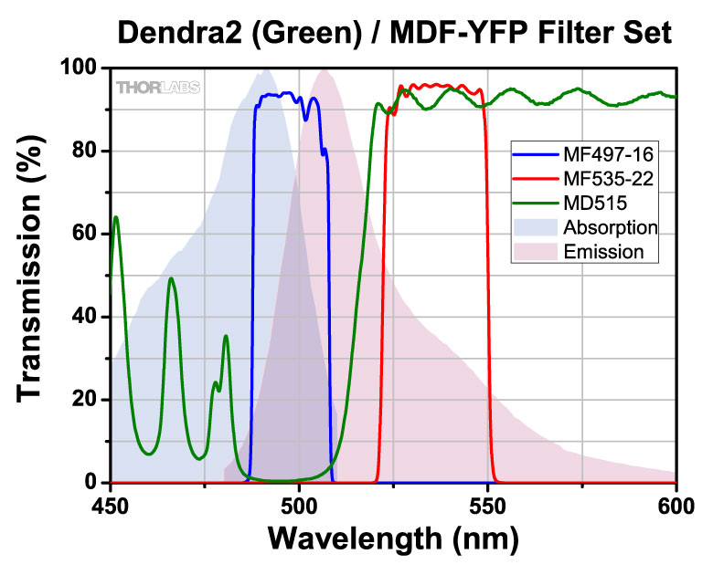
| Dendra2 (Green) (491 nm, 507 nm) | ✓✓ | ✓✓ | ✓ | ||||||||||
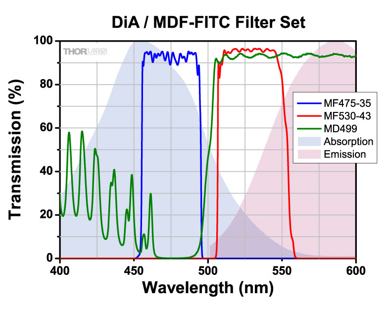
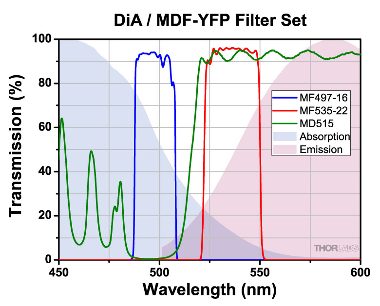
| DiA (457 nm, 586 nm) | ✓ | ✓ | ✓ | ||||||||||
| DiA (457 nm, 586 nm) | ✓ | ✓ | |||||||||||
| DiO (475 nm, 500 nm) | ✓✓✓ | ✓✓ | ✓ | ✓ | |||||||||
| Dronpa (502 nm, 516 nm) | ✓ | ✓ | ✓ | ✓ | |||||||||
| DsRed (559 nm, 583 nm) | ✓ | ✓ | ✓ | ✓ | ✓ | ||||||||
| DsRed-Express (556 nm, 584 nm) | ✓ | ✓ | ✓ | ✓ | ✓ | ||||||||
| dTomato (586 nm, 582 nm) | ✓✓✓ | ✓ | ✓ | ||||||||||
| DY-415 (418 nm, 470 nm) | ✓ | ✓ | ✓ | ||||||||||
| DY-505-Phalloidin (503 nm, 530 nm) | ✓ | ✓ | ✓✓ | ||||||||||
| DY-590 (582 nm, 599 nm) | ✓ | ✓✓ | ✓ | ✓✓ | ✓ | ||||||||
| DyLight 405 (398 nm, 420 nm) | ✓✓ | ||||||||||||
| DyLight 594 (593 nm, 618 nm) | ✓ | ✓ | ✓ | ✓ | |||||||||
| ECFP (435 nm, 475 nm) | ✓ | ✓✓ | ✓ | ||||||||||
| ecliptic pHluorin pH 5.5 (473 nm, 507 nm) | ✓✓ | ✓✓ | ✓✓ | ✓ | |||||||||
| Emerald (491 nm, 511 nm) | ✓ | ✓✓ | ✓✓ | ✓ | ✓ | ||||||||
| Eosin (525 nm, 546 nm) | ✓✓✓ | ✓✓ | |||||||||||
| ER-Tracker™ Blue-White DPX (372 nm, 557 nm) | ✓ | ||||||||||||
| Ethidium bromide (518 nm, 603 nm) | ✓ | ✓ | ✓ | ✓ | |||||||||
| Ethidium homodimer (527 nm, 617 nm) | ✓ | ✓✓ | ✓ | ✓ | ✓ | ✓ | |||||||
| evoglow-Bs1 (449 nm, 496 nm) | ✓ | ✓✓ | ✓ | ||||||||||
| FITC (Fluorescein) (495 nm, 519 nm) | ✓ | ✓✓✓ | ✓✓ | ✓✓ | |||||||||
| FlAsH-CCPFCC (511 nm, 530 nm) | ✓ | ✓✓ | ✓ | ||||||||||
| Fluo-3 (506 nm, 527 nm) | ✓ | ✓✓✓ | |||||||||||
| Fluo-4 (494 nm, 516 nm) | ✓ | ✓✓✓ | ✓✓ | ||||||||||
| Fluorescein dextran (501 nm, 524 nm) | ✓ | ✓ | ✓ | ✓✓ | |||||||||
| Fluorescein-pH 8.0 (489 nm, 517 nm) | ✓ | ✓✓ | ✓ | ✓ | |||||||||
| Fluoro-Emerald (494 nm, 518 nm) | ✓ | ✓ | ✓ | ✓✓ | |||||||||
| FluoSpheres Crimson fluorescent microspheres (620 nm, 646 nm) | ✓ | ✓ | ✓ | ||||||||||
| FluoSpheres Red fluorescent microspheres 656 nm, 683 nm) | ✓ | ✓✓ | ✓✓ | ||||||||||
| FluoSpheres Yellow-Green fluorescent microspheres (503 nm, 514 nm) | ✓ | ✓ | ✓ | ✓ | |||||||||
| FM 1-43 (473 nm, 579 nm) | ✓ | ✓ | ✓ | ✓ | ✓ | ||||||||
| GFP (EGFP) (489 nm, 511 nm) | ✓ | ✓✓ | ✓✓ | ✓ | ✓ | ||||||||
| Green 496 (496 nm, 520 nm) | ✓ | ✓✓ | ✓ | ✓✓ | |||||||||
| Green 500 (501 nm, 524 nm) | ✓ | ✓ | ✓ | ✓✓ | |||||||||
| HcRed1 (588 nm, 618 nm) | ✓ | ✓ | ✓ | ✓ | ✓ | ||||||||
| HCS LipidTOX Green neutral lipid stain (498 nm, 507 nm) | ✓✓ | ✓ | ✓ | ||||||||||
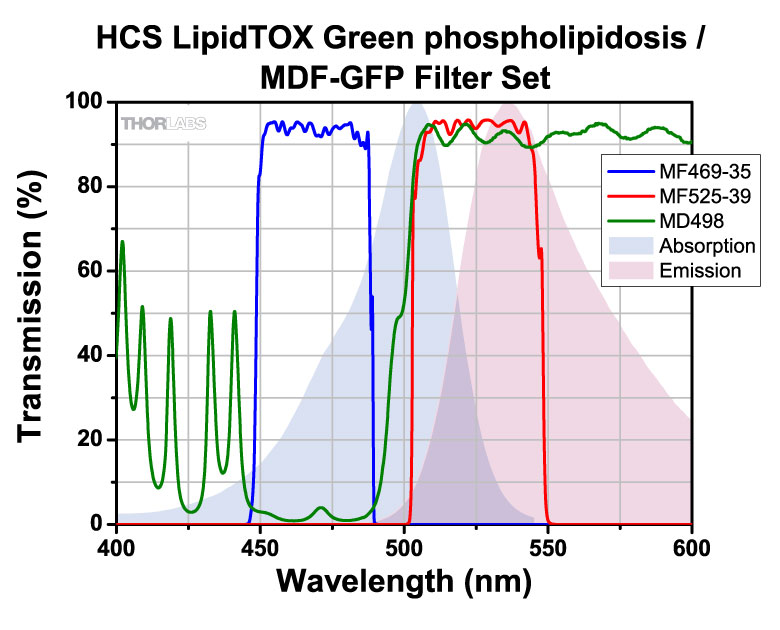
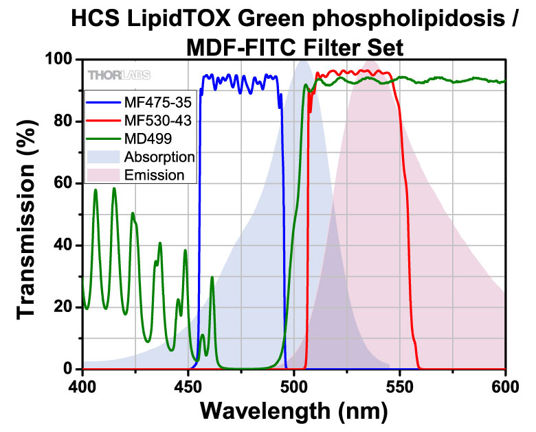
| HCS LipidTOX Green phospholipidosis (504 nm, 536 nm) | ✓ | ✓ | ✓✓ | ||||||||||
| HCS LipidTOX Red neutral lipid stain (582 nm, 616 nm) | ✓ | ✓ | ✓✓ | ✓ | ✓✓ | ✓ | |||||||
| HCS LipidTOX Red phospholipidosis (584 nm, 608 nm) | ✓ | ✓ | ✓ | ✓ | ✓ | ||||||||
| HiLyte Fluor™ 405 (403 nm, 428 nm) | ✓✓ | ||||||||||||
| HiLyte Fluor™ 488 (497 nm, 526 nm) | ✓ | ✓✓ | ✓ | ✓✓ | |||||||||
| HiLyte Fluor™ 594 (592 nm, 616 nm) | ✓ | ✓ | ✓ | ✓ | |||||||||
| Hoechst 33258 (532 nm, 455 nm) | ✓✓ | ✓ | |||||||||||
| Hoechst 33342 (352 nm, 455 nm) | ✓✓ | ||||||||||||
| Hoechst 34580 (392 nm, 440 nm) | ✓✓ | ||||||||||||
| Hypericin (600 nm, 603 nm) | ✓ | ||||||||||||
| KFP-Red (575 nm, 599 nm) | ✓ | ✓ | ✓✓ | ✓ | ✓✓ | ✓ | |||||||
| LIVE-DEAD Fixable Green Dead Cell Stain (498 nm, 525 nm) | ✓ | ✓✓ | ✓ | ✓✓ | |||||||||
| LIVE-DEAD Fixable Red Dead Cell Stain (595 nm, 613 nm) | ✓ | ✓ | ✓ | ✓ | ✓ | ||||||||
| Live-Dead Fixable Violet Dead Cell Stain (403 nm, 455 nm) | ✓✓ | ||||||||||||
| LOLO-1 (568 nm, 580 nm) | ✓ | ✓ | ✓ | ✓ | ✓ | ||||||||
| Lucifer yellow (428 nm, 544 nm) | ✓ | ✓ | |||||||||||
| LysoSensor Blue (374 nm, 424 nm) | ✓✓ | ||||||||||||
| LysoSensor Green (448 nm, 502 nm) | ✓ | ✓✓ | ✓✓ | ✓ | |||||||||
| LysoTracker Green (501 nm, 509 nm) | ✓ | ✓ | ✓ | ✓ | |||||||||
| LysoTracker Red (573 nm, 592 nm) | ✓ | ✓ | ✓✓ | ✓✓ | |||||||||
| LysoTracker Yellow HCK-123 (488 nm, 565 nm) | ✓ | ✓ | ✓ | ✓ | |||||||||
| Magnesium Green (507 nm, 531 nm) | ✓ | ✓✓ | ✓ | ||||||||||
| Magnesium Orange (587 nm, 610 nm) | ✓ | ✓ | ✓ | ✓ | ✓ | ||||||||
| mApple (566 nm, 594 nm) | ✓ | ✓ | ✓✓ | ✓ | ✓✓ | ||||||||
| Marina Blue (363 nm, 461 nm) | ✓ | ||||||||||||
| mBBr+GSH (394 nm, 490 nm) | ✓✓ | ✓ | ✓ | ||||||||||
| mCherry (587 nm, 610 nm) | ✓ | ✓✓✓ | ✓✓✓ | ✓ | ✓✓✓ | ||||||||
| Mecrocyanine 540 (559 nm, 579 nm) | ✓ | ✓ | ✓ | ||||||||||
| mHoneyDew (478 nm, 562 nm) | ✓ | ✓ | ✓ | ✓✓ | ✓ | ||||||||
| MitoTracker™ Green (490 nm, 512 nm) | ✓ | ✓✓ | ✓✓ | ✓ | ✓ | ||||||||
| MitoTracker™ Orange (551 nm, 575 nm) | ✓ | ✓ | ✓ | ✓ | |||||||||
| MitoTracker™ Red (578 nm, 598 nm) | ✓ | ✓✓ | ✓ | ✓✓ | ✓ | ||||||||
| mKate2 (588 nm, 633 nm) | ✓ | ✓ | ✓ | ✓ | ✓ | ||||||||
| mPlum (589 nm,649 nm) | ✓ | ✓ | ✓ | ✓ | |||||||||
| mRFP (555 nm, 583 nm) | ✓ | ✓ | ✓ | ✓ | ✓ | ||||||||
| mRFP1 (584 nm, 700 nm) | ✓ | ✓✓✓ | ✓✓ | ✓ | |||||||||
| mRuby (558 nm, 605 nm) | ✓ | ✓✓ | ✓✓ | ✓ | ✓✓ | ✓ | |||||||
| mStrawberry (574 nm, 596 nm) | ✓ | ✓ | ✓✓ | ✓ | ✓✓✓ | ||||||||
| mTangerine (568 nm, 585 nm) | ✓ | ✓ | ✓ | ✓ | ✓ | ✓ | |||||||
| mTFP1 (462 nm, 492 nm) | ✓ | ✓✓ | ✓ | ✓ | |||||||||
| mWasabi (493 nm, 509 nm) | ✓ | ✓✓ | ✓ | ||||||||||
| NBD-X (MeOH) (467 nm, 538 nm) | ✓ | ✓✓ | ✓✓ | ✓ | |||||||||
| NeuroTrace 500/525 Green Fluorescence Nissl Stain (495 nm, 524 nm) | ✓ | ✓✓ | ✓ | ✓✓ | |||||||||
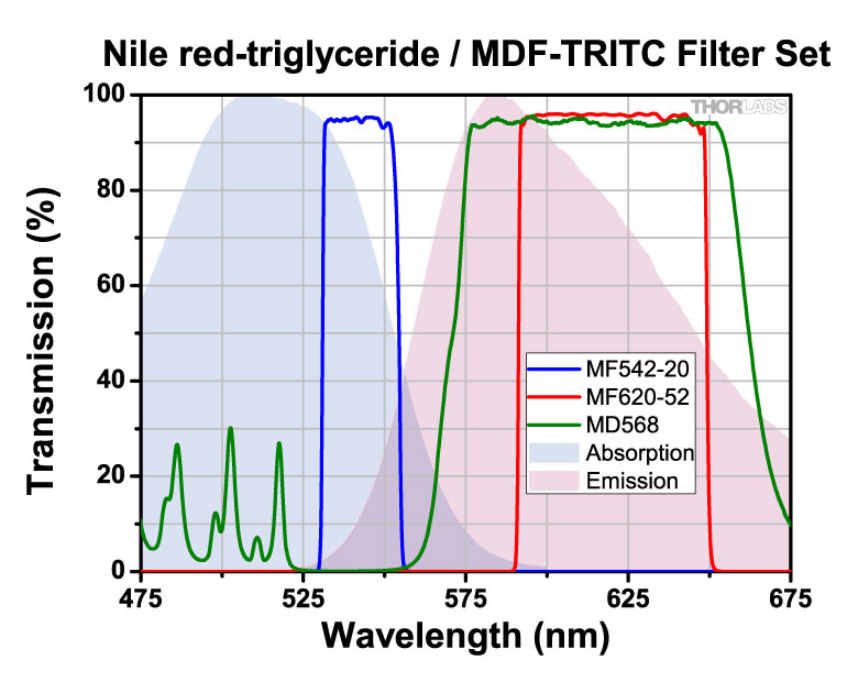
| Nile red-phospholipid (553 nm, 637 nm) | ✓✓ | ✓✓ | ✓ | ✓✓ | ✓ | ||||||||
| Nile red-triglyceride (510 nm, 583 nm) | ✓ | ✓ | |||||||||||
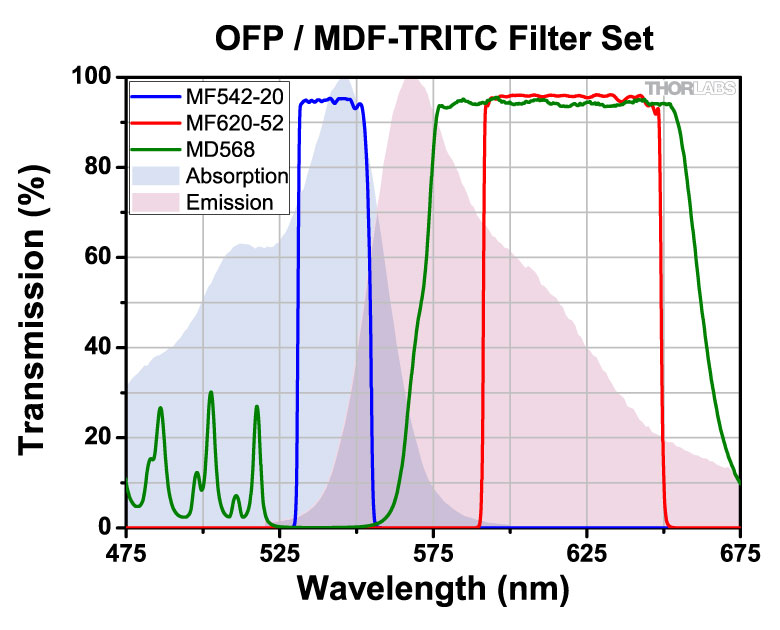
| OFP (547 nm, 567 nm) | ✓ | ✓ | ✓ | ✓ | |||||||||
| Orange 552 (552 nm, 574 nm) | ✓ | ✓ | ✓ | ✓ | |||||||||
| Oregon Green™ 488 (488 nm, 526 nm) | ✓ | ✓✓ | ✓ | ✓✓ | |||||||||
| Oregon Green™ 514 (513 nm, 532 nm) | ✓ | ||||||||||||
| Pacific Blue™ (404 nm, 455 nm) | ✓✓ | ||||||||||||
| PerCP (490 nm, 677 nm) | ✓ | ✓ | ✓ | ✓ | |||||||||
| pHrodo™, succinimidyl ester (560 nm, 587 nm) | ✓ | ✓ | ✓ | ✓ | ✓ | ||||||||
| PicoGreen (502 nm, 522 nm) | ✓ | ✓ | ✓ | ✓✓ | |||||||||
| PKH67 (488 nm, 500 nm) | ✓ | ✓✓ | ✓ | ✓ | |||||||||
| POPO-1 (433 nm, 457 nm) | ✓✓ | ✓ | |||||||||||
| PO-PRO-1 (433 nm, 456 nm) | ✓✓ | ||||||||||||
| Propidium Iodide (PI) (305 nm, 617 nm) | ✓✓ | ✓✓ | ✓ | ✓ | ✓ | ||||||||
| Pro-Q Diamond (556 nm, 583 nm) | ✓ | ✓ | ✓ | ✓ | ✓ | ||||||||
| Qdot® 525 Nanocrystals (300 nm, 525 nm) | ✓ | ✓ | ✓ | ✓ | ✓ | ||||||||
| Qdot® 545 Nanocrystals (300 nm, 543 nm) | ✓ | ||||||||||||
| Qdot® 585 Nanocrystals (300 nm, 588 nm) | ✓ | ✓ | ✓✓ | ||||||||||
| Qdot® 605 Nanocrystals (300 nm, 602 nm) | ✓ | ✓ | ✓ | ✓ | |||||||||
| Qdot® 625 Nanocrystals (300 nm, 621 nm) | ✓ | ✓ | ✓ | ✓ | |||||||||
| Qdot® 655 Nanocrystals (300 nm, 654 nm) | ✓ | ✓ | ✓ | ||||||||||
| ratiometric pHluorin pH5 (500 nm, 509 nm) | ✓ | ✓ | |||||||||||
| ReAsH-CCPGCC (592 nm, 606 nm) | ✓ | ✓ | ✓ | ✓ | ✓ | ✓ | |||||||
| Red 580 (580 nm, 603 nm) | ✓ | ✓ | ✓✓ | ✓ | ✓✓ | ✓ | |||||||
| Resorufin (571 nm, 584 nm) | ✓ | ✓ | ✓ | ✓ | ✓ | ||||||||
| Rhod-2 (553 nm, 577 nm) | ✓ | ✓ | ✓ | ✓ | |||||||||
| Rhodamine 110 (497 nm, 519 nm) | ✓ | ✓✓ | ✓ | ✓✓ | |||||||||
| Rhodamine 123 (507 nm, 529 nm) | ✓ | ✓✓✓ | |||||||||||
| Rhodamine Green (497 nm, 523 nm) | ✓ | ✓ | ✓✓ | ||||||||||
| Rhodamine phalloidin (558 nm, 575 nm) | ✓ | ✓ | ✓ | ✓ | ✓ | ||||||||
| Rhodamine Red-X (573 nm, 951 nm) | ✓ | ✓✓ | ✓✓ | ✓ | |||||||||
| Rhodol Green (497 nm, 524 nm) | ✓ | ✓✓ | ✓ | ✓✓ | |||||||||
| rsGFP (red shifted GFP, S65T) (498 nm, 516 nm) | ✓✓ | ||||||||||||
| sgBFP™ (387 nm, 451 nm) | ✓✓ | ||||||||||||
| sgGFP™ (super glow GFP) (472 nm, 506 nm) | ✓✓ | ✓✓ | ✓✓ | ✓ | |||||||||
| Sirius (355 nm, 424 nm) | ✓ | ||||||||||||
| SNARF (carboxy) 514 Excitation pH 9 (576 nm, 638 nm) | ✓ | ✓✓ | ✓✓ | ||||||||||
| SNARF-1 488 nm (pH 6.0 ) (548 nm, 586 nm) | ✓ | ✓ | ✓ | ✓ | ✓ | ||||||||
| SNARF-1 488 nm (pH 9.0) (576 nm, 638 nm) | ✓ | ✓✓ | ✓ | ✓✓ | ✓ | ||||||||
| SNARF-1 514 nm (pH 6.0 ) (549 nm, 587 nm) | ✓ | ✓✓ | ✓ | ✓ | ✓✓ | ||||||||
| SNARF-1 514 nm (pH 9.0) (576 nm, 638 nm) | ✓ | ✓✓ | ✓ | ✓✓ | ✓ | ||||||||
| Sodium Green (507 nm, 532 nm) | ✓ | ✓ | ✓ | ✓✓ | |||||||||
| SpectrumAqua (434 nm, 481 nm) | ✓✓ | ✓ | |||||||||||
| SpectrumBlue (405 nm, 449 nm) | ✓✓ | ||||||||||||
| SpectrumGreen (497 nm, 538 nm) | ✓ | ✓✓ | |||||||||||
| SpectrumOrange (554 nm, 587 nm) | ✓ | ✓ | ✓ | ✓ | ✓ | ||||||||
| SpectrumRed (587 nm, 615 nm) | ✓ | ✓ | ✓ | ||||||||||
| Sulforhodamine 101-EtOH (578 nm, 593 nm) | ✓ | ✓✓ | ✓ | ✓✓ | ✓ | ||||||||
| SYBR Gold nucleic acid gel stain-DNA (469 nm, 539 nm) | ✓ | ✓✓ | ✓✓ | ||||||||||
| SYBR Green I nucleic acid gel stain-DNA (498 nm, 522 nm) | ✓ | ✓✓ | ✓ | ✓✓ | |||||||||
| SYBR Safe DNA gel stain-DNA (509 nm, 526 nm) | ✓ | ✓ | ✓✓ | ||||||||||
| SYTO 9 (483 nm, 500 nm) | ✓ | ✓✓ | ✓ | ✓✓ | |||||||||
| SYTO 11 (506 nm, 525 nm) | ✓ | ✓ | ✓✓ | ||||||||||
| SYTO 13 (448 nm, 506 nm) | ✓✓ | ✓✓ | ✓ | ✓ | |||||||||
| SYTO 16 (489 nm, 520 nm) | ✓✓ | ✓✓ | ✓ | ✓✓ | |||||||||
| SYTO 45 (451 nm, 485 nm) | ✓ | ✓✓ | ✓ | ✓ | |||||||||
| SYTO RNASelect green fluorescent cell stain (503 nm, 527 nm) | ✓ | ✓ | ✓ | ✓✓ | |||||||||
| SYTOX Blue (444 nm, 470 nm) | ✓✓✓ | ✓ | |||||||||||
| SYTOX Green-DNA (504 nm, 524 nm) | ✓ | ✓ | ✓ | ✓✓ | |||||||||
| TagBFP (402 nm, 457 nm) | ✓✓ | ||||||||||||
| TagCFP (458 nm, 480 nm) | ✓✓ | ✓ | ✓ | ✓ | |||||||||
| tdTomato (556 nm, 582 nm) | ✓✓✓ | ||||||||||||
| Tetramethylrhodamine dextran (554 nm, 582 nm) | ✓ | ✓ | ✓ | ✓ | ✓ | ||||||||
| Texas Red dextran (592 nm, 613 nm) | ✓ | ✓ | ✓ | ✓ | ✓ | ||||||||
| Texas Red DHPE (584 nm, 608 nm) | ✓ | ✓ | ✓ | ✓ | ✓ | ✓ | |||||||
| Texas Red® (592 nm, 614 nm) | ✓✓✓ | ✓✓ | ✓ | ✓ | |||||||||
| ThiolTracker Violet GSH (404 nm, 526 nm) | ✓ | ✓ | |||||||||||
| TO-PRO-1 (515 nm, 531 nm) | ✓ | ✓ | ✓ | ||||||||||
| TOTO-1 (514 nm, 531 nm) | ✓ | ✓ | ✓ | ✓ | ✓ | ||||||||
| TRITC (Tertamethylrhodamine) (552 nm, 578 nm) | ✓ | ✓ | ✓ | ✓ | |||||||||
| TRITC (Tertamethylrhodamine) - "reddish" (552 nm, 578 nm) | ✓✓ | ||||||||||||
| TurboFP635 (Katushka) (591 nm, 638 nm) | ✓ | ✓ | ✓ | ✓ | |||||||||
| TurboGFP (482 nm, 503 nm) | ✓ | ✓✓ | ✓✓ | ✓ | |||||||||
| TurboRFP (553 nm, 573 nm) | ✓ | ✓ | ✓ | ✓ | ✓ | ||||||||
| TurboYFP (525 nm, 538 nm) | ✓ | ✓ | |||||||||||
| Venus (516 nm, 528 nm) | ✓ | ✓ | ✓ | ||||||||||
| Vybrant DyeCycle Green (506 nm, 534 nm) | ✓ | ✓ | ✓ | ✓✓ | |||||||||
| Vybrant DyeCycle Orange (519 nm, 563 nm) | ✓ | ✓ | |||||||||||
| Vybrant DyeCycle Violet (369 nm, 437 nm) | ✓ | ||||||||||||
| wtGFP (wild type GFP, non-UV excitation) (474 nm, 509 nm) | ✓✓✓ | ✓✓ | ✓✓ | ✓ | |||||||||
| X-Rhod-1 Indicator (580 nm, 601 nm) | ✓ | ✓ | ✓✓ | ✓✓ | ✓✓ | ✓✓ | |||||||
| YFP (yellow GFP) (513 nm, 530 nm) | ✓ | ✓✓✓ | ✓✓ | ||||||||||
| YO-PRO-1 (491 nm, 506 nm) | ✓ | ✓✓ | ✓✓ | ✓ | ✓ | ||||||||
| YOYO-1 (491 nm, 508 nm) | ✓ | ✓✓ | ✓✓ | ✓ | ✓ | ||||||||
| YOYO-3 (611 nm, 631 nm) | ✓ | ✓ | ✓ | ✓ |
| Posted Comments: | |
宇佐川 元久
(posted 2024-02-08 09:30:56.487) GaN(365nm)の蛍光観察を行いたいと考えており、
365nm以下の波長で励起⇒365nmの波長を観察できる
フィルターキューブを検討しております。
ご対応可能でしょうか? cdolbashian
(posted 2024-02-19 11:04:48.0) Thank you for reaching out to us with the following inquiry:
"I would like to perform fluorescence observation of GaN (365nm).
Excitation at a wavelength of 365nm or less ⇒ 365nm wavelength can be observed. I'm considering a filter cube. Is that possible?"
Unfortunately, we do not have dichroic mirrors and filters which can be used at this wavelength. |
")
 Zoom
Zoom
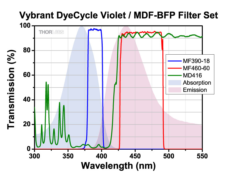
| Item # Suffix | -BFP |
|---|---|
| Design Fluorophore | Blue Fluorescent Protein (BFP) |
| Excitation Band | 390 ± 9 nm |
| Emission Band | 460 ± 30 nm |
| Dichroic Band (R/T) | 360 - 407 nm / 425 - 575 nm |
| Transmission Dataa | |
| Filter Set Item # | MDF-BFP |
- Click on for additional plots and downloadable data.
")
 Zoom
Zoom
| Item # Suffix | -CFP |
|---|---|
| Design Fluorophore | Cyan Fluorescent Protein (CFP) |
| Excitation Band | 434 ± 8.5 nm |
| Emission Band | 479 ± 20 nm |
| Dichroic Band (R/T) | 423 - 445 nm / 460 - 610 nm |
| Transmission Dataa | |
| Filter Set Item # | MDF-CFP |
- Click on for additional plots and downloadable data.
")
 Zoom
Zoom
| Item # Suffix | -WGFP |
|---|---|
| Design Fluorophore | Wild Type GFP (WGFP) |
| Excitation Band | 445 ± 22.5 nm |
| Emission Band | 510 ± 21 nm |
| Dichroic Band (R/T) | 415 - 470 nm / 490 - 720 nm |
| Transmission Dataa | |
| Filter Set Item # | MDF-WGFP |
- Click on for additional plots and downloadable data.
")
 Zoom
Zoom
| Item # Suffix | -GFP |
|---|---|
| Design Fluorophore | Green Fluorescent Protein (GFP) |
| Excitation Band | 469 ± 17.5 nm |
| Emission Band | 525 ± 19.5 nm |
| Dichroic Band (R/T) | 452 - 490 nm / 505 - 800 nm |
| Transmission Dataa | |
| Filter Set Item # | MDF-GFP |
- Click on for additional plots and downloadable data.
")
 Zoom
Zoom
| Item # Suffix | -FITC |
|---|---|
| Design Fluorophore | Fluorescein Isothiocyanate (FITC) |
| Excitation Band | 475 ± 17.5 nm |
| Emission Band | 530 ± 21.5 nm |
| Dichroic Band | 470 - 490 nm / 508 - 675 nm |
| Transmission Dataa | |
| Filter Set Item # | MDF-FITC |
- Click on for additional plots and downloadable data.
")
 Zoom
Zoom
| Item # Suffix | -GFP2 |
|---|---|
| Design Fluorophore | Alexa Fluor® 488 / Green Fluorescent Protein (GFP) |
| Excitation Band | 482 ± 9 nm |
| Emission Band | 520 ± 14 nm |
| Dichroic Band (R/T) | 350 - 488 nm / 502 - 950 nm |
| Transmission Dataa | |
| Filter Set Item # | MDF-GFP2 |
- Click on for additional plots and downloadable data.
")
 Zoom
Zoom| Item # Suffix | -YFP |
|---|---|
| Design Fluorophore | Yellow Fluorescent Protein (YFP) |
| Excitation Band | 497 ± 8 nm |
| Emission Band | 535 ± 11 nm |
| Dichroic Band | 490 - 510 nm / 520 - 700 nm |
| Filter Set Transmission Dataa | |
| Filter Set Item # | MDF-YFP |
- Click on for additional plots and downloadable data.
")
 Zoom
Zoom
| Item # Suffix | -TOM |
|---|---|
| Design Fluorophore | tdTomato |
| Excitation Band | 531 ± 20 nm |
| Emission Band | 593 ± 20 nm |
| Dichroic Band (R/T) | 350 - 555 nm / 569 - 950 nm |
| Transmission Dataa | |
| Filter Set Item # | MDF-TOM |
- Click on for additional plots and downloadable data.
")
 Zoom
Zoom
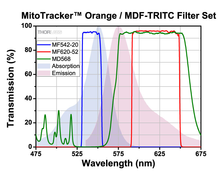
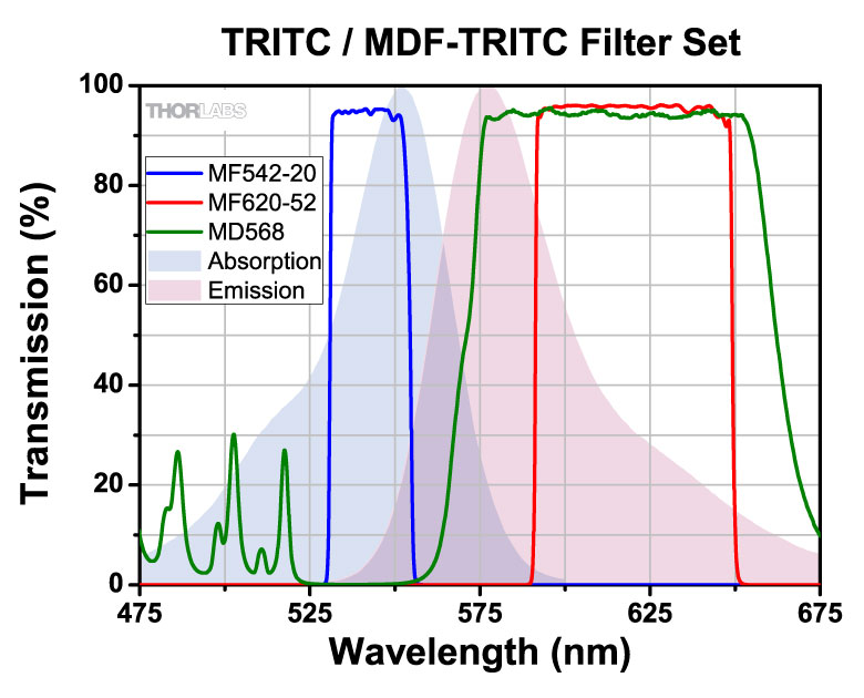
| Item # Suffix | -TRITC |
|---|---|
| Design Fluorophore | Tetramethylrhodamine Isothiocyanate (TRITC) |
| Excitation Band | 542 ± 10 nm |
| Emission Band | 620 ± 26 nm |
| Dichroic Band (R/T) | 525 - 556 nm / 580 - 650 nm |
| Transmission Dataa | |
| Filter Set Item # | MDF-TRITC |
- Click on for additional plots and downloadable data.
")
 Zoom
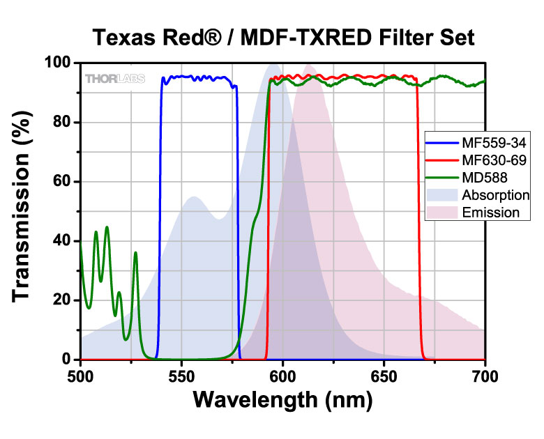
Zoom
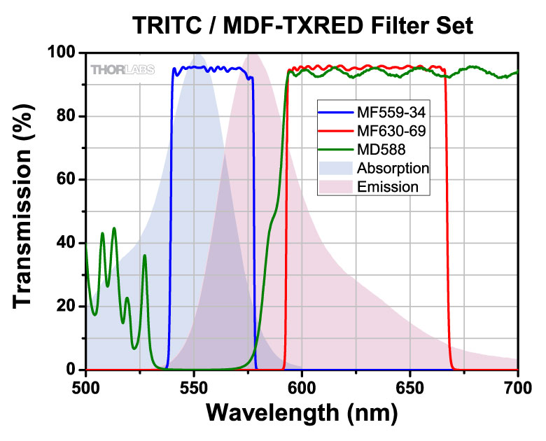
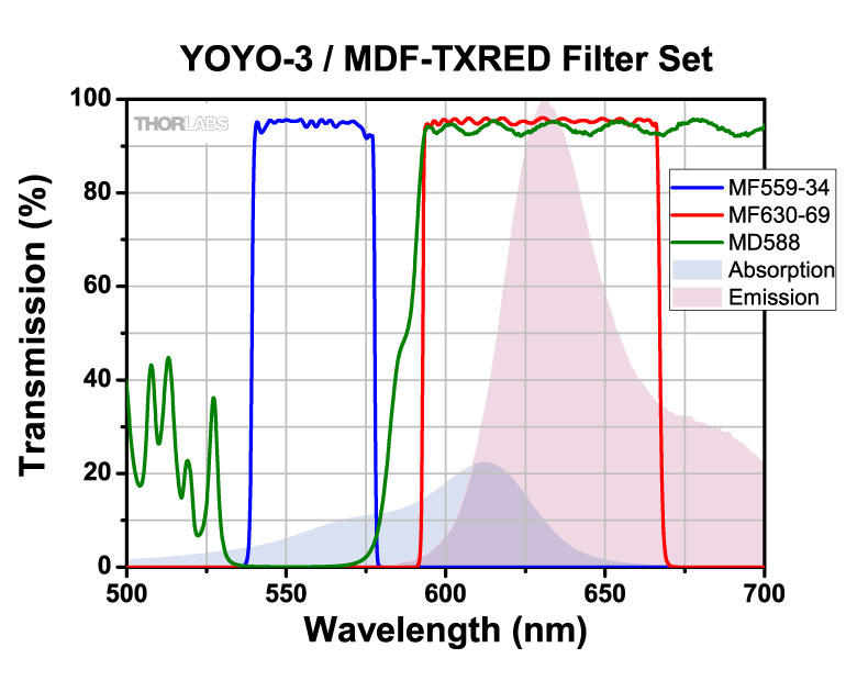
| Item # Suffix | -TXRED |
|---|---|
| Design Fluorophore | Texas Red (TXRED) |
| Excitation Band | 559 ± 17 nm |
| Emission Band | 630 ± 34.5 nm |
| Dichroic Band (R/T) | 533 - 580 nm / 595 - 800 nm |
| Transmission Dataa | |
| Filter Set Item # | MDF-TXRED |
- Click on for additional plots and downloadable data.
")
 Zoom
Zoom
| Item # Suffix | -MCHC |
|---|---|
| Design Fluorophore | mCherry |
| Excitation Band | 562 ± 20 nm |
| Emission Band | 641 ± 37.5 nm |
| Dichroic Band (R/T) | 350 - 585 nm / 601 - 950 nm |
| Transmission Dataa | |
| Filter Set Item # | MDF-MCHC |
- Click on for additional plots and downloadable data.
")
 Zoom
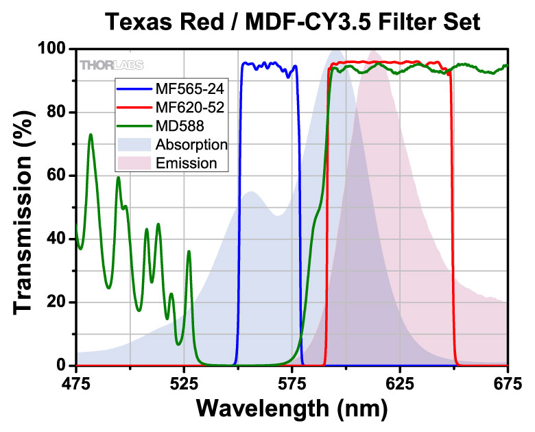
Zoom
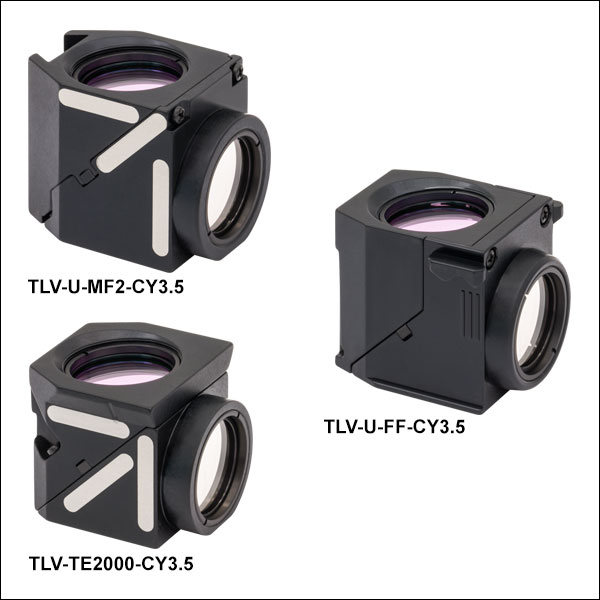
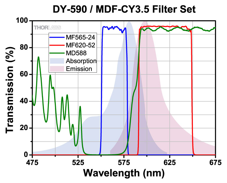
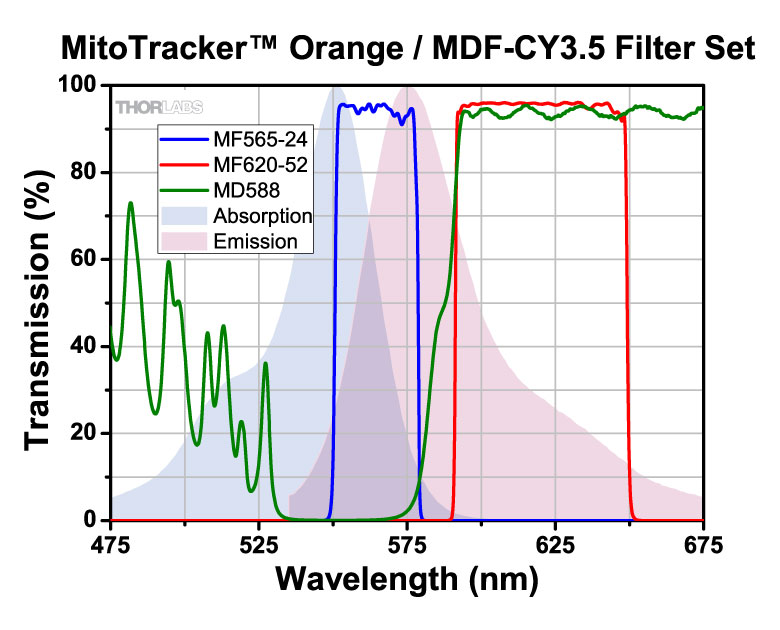
| Item # Suffix | -CY3.5 |
|---|---|
| Design Fluorophore | Cyanine (CY3.5) |
| Excitation Band | 565 ± 12 nm |
| Emission Band | 620 ± 26 nm |
| Dichroic Band (R/T) | 533 - 580 nm / 595 - 800 nm |
| Transmission Dataa | |
| Filter Set Item # | MDF-CY3.5 |
- Click on for additional plots and downloadable data.
<br>")
 Zoom
Zoom
.jpg)
.jpg)
.gif)
.jpg)
| Item # Suffix | -MCHA |
|---|---|
| Design Fluorophore | mCherry |
| Excitation Band | 578 ± 10.5 nm |
| Emission Band | 641 ± 37.5 nm |
| Dichroic Band (R/T) | 350 - 588 nm / 603 - 950 nm |
| Transmission Dataa | |
| Filter Set Item # | MDF-MCHA |
- Click on for additional plots and downloadable data.