 Products Home / Lasers / Coherent Sources / Tunable Lasers / Fiber-Coupled, Rack-Mounted Tunable Laser Sources
Fiber-Coupled, Rack-Mounted Tunable Laser Sources
- TLX3: Tunable Laser for O-Band (1250 - 1350 nm)
- TLX5: Tunable Laser for C+L Band (1520 - 1630 nm)
- Sweep Speeds Up to 400 nm/s
- Remote Control via USB or RS-232 Connections
TLX3
Tunable Laser Source, O-Band
Software GUI for TLX3 Tunable Laser
TLX5
Tunable Laser Source, C+L Band


Please Wait
| Key Specifications | ||
|---|---|---|
| Item # | TLX3 | TLX5 |
| Wavelength Range (Typ.) | 1250 nm - 1350 nm | 1520 nm - 1630 nm |
| Output Powera | 10 - 40 mW | |
| Power Stability | ±0.02 dB | |
| Power Repeatability | ±0.05 dB | ±0.02 dB |
| Wavelength Accuracy | ±50 pm | ±30 pm |
| Wavelength Stability | ±30 pm | ±15 pm |
| Wavelength Repeatability | ±20 pm | ±5 pm |
| Tuning Resolution | 10 pm | 2 pm |
| Linewidth | <100 kHz | |
Demo Units Available
Interested in trying the TLX3 or TLX5 Rack-Mounted Tunable Laser Sources for your application?Contact us at techsales@thorlabs.com to request a demo unit.
Features
- Turnkey Tunable Laser Sources
- TLX3: 1250 nm - 1350 nm (O-Band)
- TLX5: 1520 nm - 1630 nm (C+L Band)
- Three Operating Modes: Manual, Stepped Sweep, or Continuous Sweep
- PM Fiber Output with Narrow-Key FC/APC Connector
- Trigger Signal and Clock Output for Synchronization with External Instrumentation
- Control via Included Software GUI or SCPI Commands
- 2U Housing Designed for 19" Racks

Janis Valdmanis, Ph.D. Optics
Ultrafast Optoelectronics
General Manager
Need a Quote?
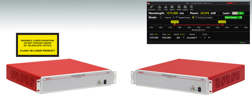
Thorlabs' TLX3 and TLX5 Tunable Lasers are turnkey, self-contained, tunable lasers for the O-Band (1250 nm to 1350 nm) or C+L Band (1520 nm to 1630 nm) wavelength ranges, respectively. Both lasers are based on the use of a fiber-coupled, semiconductor gain module and an intracavity tunable filter. These instruments are designed for fast, continuous wavelength tuning at up to 400 nm/s. The TLX3 laser achieves 10 pm tuning resolution and ±50 pm wavelength accuracy, while the TLX5 laser achieves 2 pm tuning resolution and ±30 pm wavelength accuracy. With output power in the 10 mW to 40 mW range and polarization-maintaining single mode output, these lasers are ideal sources for communication applications and manufacturing testing. For maximum measurement flexibility, these tunable lasers can be operated in three modes: manual, stepped sweep, and continuous sweep.
The optical output for these instruments is fiber-coupled via an FC/APC connector, and single mode or polarization maintaining fiber patch cables designed for operation in the O-band or C+L band wavelength ranges can be connected. Note that the polarization axis is aligned with the narrow key of the bulkhead connector, as well as the slow-axis of the connected PM fiber.
BNC connectors for a Trigger Out and a Sync Clock Output are included on the back panel of these lasers. The Trigger Out connector provides a 4.1 V digital signal for synchronizing external instruments to the Stepped Sweep and Continuous Sweep modes, while the Sync Clock Output provides a series of 3.3 V pulses for synchronizing to the continuous sweep of the lasers. Additionally, the Trigger Out connector on the TLX5 tunable laser will also provide signal for synchronizing the Wavelength Locking feature. For more details on these outputs, please see the user guide.

Click to Enlarge
The Rack-Mounted Tunable Laser operation mode can be changed to manual, stepped-sweep, or continuous sweep using the software GUI. See the Software tab for more information.
Software
A user-friendly GUI is included with these instruments, which allows the user to select between the manual, stepped sweep, and continuous sweep modes. Operating parameters for each mode can also be set within the GUI, and direct readout of the operating wavelength and output power are also provided. Please see the Software tab for more information on each operating mode.
These lasers can also be operated without the software GUI via SCPI-type serial commands, which requires the instrument to be connected to the PC using the RS-232 or USB ports (see Pin Diagrams tab) on the back panel. A programming guide containing supporting commands is available for download. Note that the software GUI installer also installs the required driver for USB remote control. The installer is not required for remote control over the RS-232 interface.
A Boot Mode button and LED indicator for use during firmware updates is also included on the back panel of this instrument. Note that this button is not used in normal operation and instructions for using this button will be included with the release of firmware updates.
Mounting and Accessories
Designed for use with a standard 19" equipment rack, the TLX3 and TLX5 lasers housings have a height of 2U and include mounting brackets. Each bracket has two 0.28" x 0.28" (7.0 mm x 7.2 mm) slots for standard rack mounting screws, which are not included. Alternatively, four attachable feet are included with the lasers for benchtop use; for a complete list of accessories, see the Shipping List tab.
All specifications are typical at 25 °C after a 1 hour warm-up time.
| Item # | TLX3 | TLX5 |
|---|---|---|
| Wavelength Range (Typ.) | 1250 - 1350 nm | 1520 - 1630 nm |
| Output Powera | 10 - 40 mW | |
| Spectral Response (Typ.) |  Raw Data |
 Raw Data |
| Power Stability | ±0.02 dB | |
| Power Repeatability | ±0.05 dB | ±0.02 dB |
| Wavelength Accuracy | ±50 pm | ±30 pm |
| Wavelength Stability | ±30 pm | ±15 pm |
| Wavelength Repeatability | ±20 pm | ±5 pm |
| Tuning Resolution | 10 pm | 2 pm |
| ASE Ratiob | >60 dB | |
| RIN Noise | -145 dB/Hz | |
| Linewidth | <100 kHz | |
| Tuning Time (Manual Mode)c | 100 ms | 1000 ms (Max) |
| Transition Time (Step Mode)d | 300 ms | |
| Dwell Time (Step Mode)e | 100 ms - 60 s | |
| Sweep Speed Rangef | 50 - 400 nm/s | |
| Output Connector | 2.0 mm Narrow-Key FC/APC (PM) | |
| Output Fiberg | Single-Mode PM | |
| Polarization Extinction Ratio | >15 dB | |
| Operating Conditions | 10 - 35 °C, 5% - 85% Relative Humidity | |
| Housing Sizeh | 482.6 mm x 429.0 mm x 86.0 mm (19.00" x 16.89" x 3.39") |
|
| Supply Voltage | 90 - 250 VAC, 50/60 Hz | |
| Trigger Out Levels (Digital) | 0 - 4.1 V | |
| Clock Out Levels (Digital) | 0 - 3.3 V | |
Front and Back Panels
Click for Details
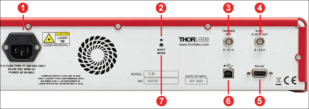
Tunable Laser Source Back Panel
Click for Details
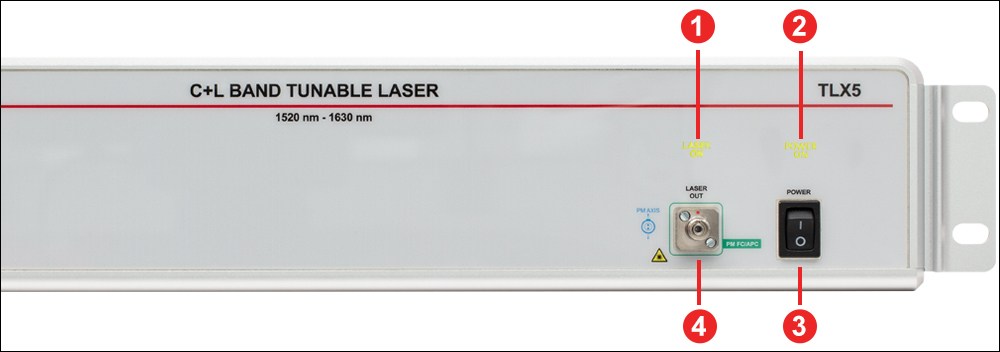
Tunable Laser Source Front Panel
| Back Panel | |
|---|---|
| Callout | Description |
| 1 | Main Power Connection |
| 2 | Indicator LED for Firmware Upgrades |
| 3 | Trigger Signal (BNC Female Connector) |
| 4 | Clock Output (BNC Female Connector) |
| 5 | RS-232 Port (DB9 Female Connector) |
| 6 | USB Port (USB Type B Connector) |
| 7 | Boot Mode Buttona |
| Front Panel | |
|---|---|
| Callout | Description |
| 1 | Indicator Light for Laser Output |
| 2 | Indicator Light for Laser Power |
| 3 | Power Switch |
| 4 | PM FC/APC Fiber Output |
Software
Version 2.0.1
Click the link below to download the TLXGo Laser Software.
Software for the TLX3 and TLX5 Tunable Laser Sources
Control the Laser Source via the TLXGo Software GUI
The TLXGo Laser Software is designed for straightforward use of the TLX3 and TLX5 Tunable Laser Sources. This software GUI provides full control over the laser, and allows the user to power the laser on and off, select the operation mode, and set system parameters. Laser status, operating wavelength, and laser power are also provided. The software requires a computer running Windows® 10 or 11 operating systems.
Control the Laser Source via Serial Commands
Serial commands sent to the lasers can turn the laser on or off, set general system parameters, and set sweep parameters. The commands can be sent from a computer running Windows® 10 or 11 operating systems to the USB or RS-232 ports on the back panel of the instrument. Descriptions of each command are included in the Programming Guide. Note that the software GUI installer also installs the required driver for USB remote control.
The installer is not required for remote control over the RS-232 interface.
Laser Operation Modes
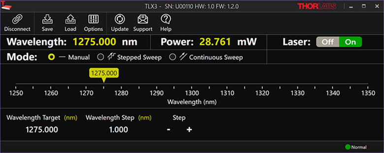
The images below are examples of the TLXGo software GUI when used to control the TLX3 tunable laser. When the TLX5 tunable laser is connected, the GUI will have the same appearance and operation modes but display a different wavelength range. The appropriate GUI is chosen by selecting the COM port associated with the desired laser upon starting the software.
Click to Enlarge
Manual Mode: allows the user to precisely step the operating wavelength manually. The operating wavelength can be set directly in the "Wavelength Target" box or by dragging the yellow indicator above the wavelength scale. The step size can be set in the "Wavelength Step" box, and the wavelength can be stepped up or down using the "+" or "-" indicators, respectively.

Click to Enlarge
Continuous Sweep: allows the user to automatically sweep across a wavelength range. The beginning and ending wavelengths can be set in the "Start" and "Stop" boxes, or the range can be set by dragging the yellow indicators above the wavelength scale. The active range appears red on the scale. The user can set the sweep speed and number of cycles (fixed number or infinite).
Click to Enlarge
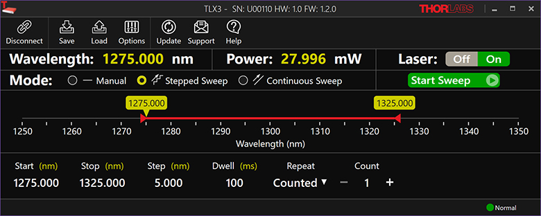
Stepped Sweep: allows the user to automatically step across a wavelength range. The beginning and ending wavelengths can be set in the "Start" and "Stop" boxes, or the range can be set by dragging the yellow indicators above the wavelength scale. The active range appears red on the scale. The user can also set the step size, dwell time, and the number of sweep cycles (fixed number or infinite).
RS-232 Connector (Female)
The RS-232 connector is provided to support remote operation.
| Pin | Description |
|---|---|
| 1 | Not Connected |
| 2 | Transmit (Output) |
| 3 | Receive (Input) |
| 4 | Not Connected |
| 5 | Digital Ground |
| 6 | Not Connected |
| 7 | Not Connected |
| 8 | Not Connected |
| 9 | Not Connected |
USB, Type B (Female)
The USB connector is provided to support remote operation.
Click to Enlarge
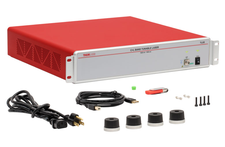
Rack-Mounted Tunable Laser Source and Accessories
Each Rack-Mounted Tunable Laser Source includes the following:
- Laser Source Main Unit
- Location-Specific Power Cord
- USB Type-A to USB Type-B Cable
- USB Drive with Software
- Four Attachable Rubber Feet for Benchtop Use
- Four M4 x 16 Screws for Mounting the Rubber Feet
- Two Spare 1.25 A, 250 VAC Fuses
- Cap for Fiber Output
- Printed Copy of the User Guide
Laser Safety and Classification
Safe practices and proper usage of safety equipment should be taken into consideration when operating lasers. The eye is susceptible to injury, even from very low levels of laser light. Thorlabs offers a range of laser safety accessories that can be used to reduce the risk of accidents or injuries. Laser emission in the visible and near infrared spectral ranges has the greatest potential for retinal injury, as the cornea and lens are transparent to those wavelengths, and the lens can focus the laser energy onto the retina.
 |
 |
 |
 |
 |
 |
 |
 |
 |
Safe Practices and Light Safety Accessories
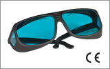
- Laser safety eyewear must be worn whenever working with Class 3 or 4 lasers.
- Regardless of laser class, Thorlabs recommends the use of laser safety eyewear whenever working with laser beams with non-negligible powers, since metallic tools such as screwdrivers can accidentally redirect a beam.
- Laser goggles designed for specific wavelengths should be clearly available near laser setups to protect the wearer from unintentional laser reflections.
- Goggles are marked with the wavelength range over which protection is afforded and the minimum optical density within that range.
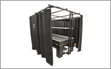
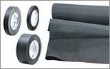
- Laser Safety Curtains and Laser Safety Fabric shield other parts of the lab from high energy lasers.
- Blackout Materials can prevent direct or reflected light from leaving the experimental setup area.
- Thorlabs' Enclosure Systems can be used to contain optical setups to isolate or minimize laser hazards.
- A fiber-pigtailed laser should always be turned off before connecting it to or disconnecting it from another fiber, especially when the laser is at power levels above 10 mW.
- All beams should be terminated at the edge of the table, and laboratory doors should be closed whenever a laser is in use.
- Do not place laser beams at eye level.
- Carry out experiments on an optical table such that all laser beams travel horizontally.
- Remove unnecessary reflective items such as reflective jewelry (e.g., rings, watches, etc.) while working near the beam path.
- Be aware that lenses and other optical devices may reflect a portion of the incident beam from the front or rear surface.
- Operate a laser at the minimum power necessary for any operation.
- If possible, reduce the output power of a laser during alignment procedures.
- Use beam shutters and filters to reduce the beam power.
- Post appropriate warning signs or labels near laser setups or rooms.
- Use a laser sign with a lightbox if operating Class 3R or 4 lasers (i.e., lasers requiring the use of a safety interlock).
- Do not use Laser Viewing Cards in place of a proper Beam Trap.
Laser Classification
Lasers are categorized into different classes according to their ability to cause eye and other damage. The International Electrotechnical Commission (IEC) is a global organization that prepares and publishes international standards for all electrical, electronic, and related technologies. The IEC document 60825-1 outlines the safety of laser products. A description of each class of laser is given below:
| Class | Description | Warning Label |
|---|---|---|
| 1 | This class of laser is safe under all conditions of normal use, including use with optical instruments for intrabeam viewing. Lasers in this class do not emit radiation at levels that may cause injury during normal operation, and therefore the maximum permissible exposure (MPE) cannot be exceeded. Class 1 lasers can also include enclosed, high-power lasers where exposure to the radiation is not possible without opening or shutting down the laser. |  |
| 1M | Class 1M lasers are safe except when used in conjunction with optical components such as telescopes and microscopes. Lasers belonging to this class emit large-diameter or divergent beams, and the MPE cannot normally be exceeded unless focusing or imaging optics are used to narrow the beam. However, if the beam is refocused, the hazard may be increased and the class may be changed accordingly. |  |
| 2 | Class 2 lasers, which are limited to 1 mW of visible continuous-wave radiation, are safe because the blink reflex will limit the exposure in the eye to 0.25 seconds. This category only applies to visible radiation (400 - 700 nm). |  |
| 2M | Because of the blink reflex, this class of laser is classified as safe as long as the beam is not viewed through optical instruments. This laser class also applies to larger-diameter or diverging laser beams. |  |
| 3R | Class 3R lasers produce visible and invisible light that is hazardous under direct and specular-reflection viewing conditions. Eye injuries may occur if you directly view the beam, especially when using optical instruments. Lasers in this class are considered safe as long as they are handled with restricted beam viewing. The MPE can be exceeded with this class of laser; however, this presents a low risk level to injury. Visible, continuous-wave lasers in this class are limited to 5 mW of output power. |  |
| 3B | Class 3B lasers are hazardous to the eye if exposed directly. Diffuse reflections are usually not harmful, but may be when using higher-power Class 3B lasers. Safe handling of devices in this class includes wearing protective eyewear where direct viewing of the laser beam may occur. Lasers of this class must be equipped with a key switch and a safety interlock; moreover, laser safety signs should be used, such that the laser cannot be used without the safety light turning on. Laser products with power output near the upper range of Class 3B may also cause skin burns. |  |
| 4 | This class of laser may cause damage to the skin, and also to the eye, even from the viewing of diffuse reflections. These hazards may also apply to indirect or non-specular reflections of the beam, even from apparently matte surfaces. Great care must be taken when handling these lasers. They also represent a fire risk, because they may ignite combustible material. Class 4 lasers must be equipped with a key switch and a safety interlock. |  |
| All class 2 lasers (and higher) must display, in addition to the corresponding sign above, this triangular warning sign. |  |
|
Janis Valdmanis, Ph.D. Optics
Ultrafast Optoelectronics
General Manager
Custom and OEM Options
When your application requirements are not met by our range of catalog products or their variety of user-configurable features, please contact me to discuss how we may serve your custom or OEM needs.
Request a Demo Unit
Explore the benefits of using a Thorlabs high-speed instrument in your setup and under your test conditions with a demo unit. Contact me for details.
![]()

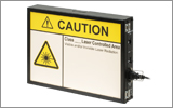
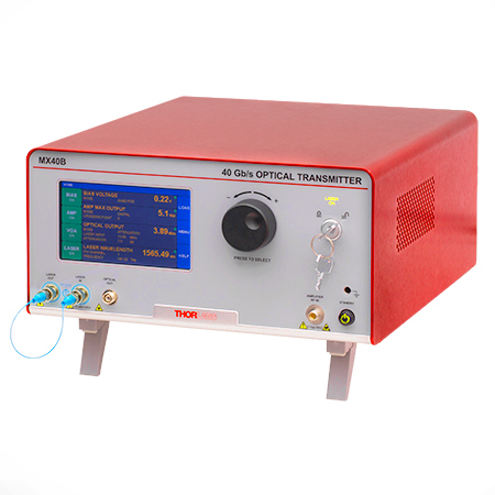
Click to Enlarge
The MX40B Digital Reference Transmitter
Design, Manufacturing, and Testing Capabilities
Thorlabs' Ultrafast Optoelectronics Team designs, develops, and manufactures high-speed components and instrumentation for a variety of photonics applications having frequency responses up to 110 GHz. Our extensive experience in high-speed photonics is supported by core expertise in RF/microwave design, optics, fiber optics, optomechanical design, and mixed-signal electronics. As a division of Thorlabs, a company with deep vertical integration and a portfolio of over 20,000 products, we are able to provide and support a wide selection of equipment and continually expand our offerings.
Our catalog and custom products include a range of integrated fiber-optic transmitters, modulator drivers and controllers, detectors, receivers, pulsed lasers, variable optical attenuators, and a variety of accessories. Beyond these products, we welcome opportunities to design and produce custom and OEM products that fall within our range of capabilities and expertise. Some of our key capabilities are:
- Detector and Receiver Design, to 70 GHz
- Fiber-Optic Transmitter Design, to 110 GHz
- RF & Microwave Design and Simulation
- Design of Fiber-Optic and Photonics Sub-Assemblies
- High-Speed Testing, to 110 GHz
- Micro-Assembly and Wire Bonding
- Hermetic Sealing of Microwave Modules
- Fiber Splicing of Assemblies
- Custom Laser Engraving
- Qualification Testing
Overview of Custom and Catalog Products
Our catalog product line includes a range of integrated fiber-optic transmitters, modulator drivers and controllers, detectors, pulsed lasers, and accessories. In addition to these, we offer related items, such as receivers and customized catalog products. The following sections give an overview of our spectrum of custom and catalog products, from fully integrated instruments to component-level modules.
Fiber-Optic Instruments
To meet a range of requirements, our fiber-optic instruments span a variety integration levels. Each complete transmitter includes a tunable laser, a modulator with driver amplifier and bias controller, full control of optical output power, and an intuitive touchscreen interface. The tunable lasers, modulator drivers, and modulator bias controllers are also available separately. These instruments have full remote control capability and can be addressed using serial commands sent from a PC.
- Fiber-Optic Transmitters, to 110 GHz
- Linear and Digital Transmitters
- Electrical-to-Optical Converters, to 110 GHz
- Modulator Drivers
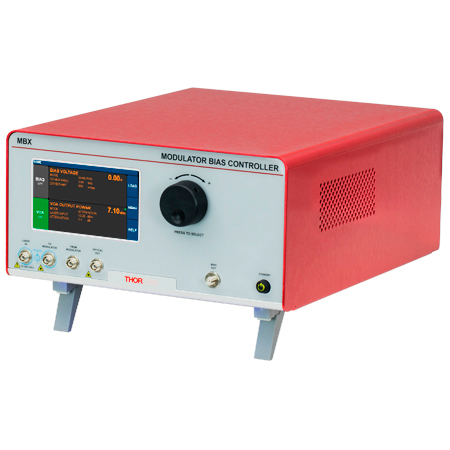
- Modulator Bias Controllers
- C- and L-Band Tunable Lasers
Customization options include internal laser sources, operating wavelength ranges, optical fiber types, and amplifier types.
Fiber-Optic Components
Our component-level, custom and catalog fiber-optic products take advantage of our module design and hermetic sealing capability. Products include detectors with frequency responses up to 50 GHz, and we also specialize in developing fiber-optic receivers, operating up to and beyond 40 GHz, for instrumentation markets. Closely related products include our amplifier modules, which we offer upon request, variable optical attenuators, microwave cables, and cable accessories.
- Hermetically-Sealed Detectors, to 50 GHz
- Fiber-Optic Receivers, to 40 GHz
- Amplifier Modules
- Electronic Variable Optical Attenuators
- Microwave Cables and Accessories
Customization options include single mode and multimode optical fiber options, where applicable, and detectors optimized for time or frequency domain operation.
Free-Space Instruments
Our free-space instruments include detectors with frequency responses around 1 GHz and pulsed lasers. Our pulsed lasers generate variable-width, nanosecond-duration pulses, and a range of models with different wavelengths and optical output powers are offered. User-adjustable repetition rates and trigger in/out signals provide additional flexibility, and electronic delay-line products enable experimental synchronization of multiple lasers. We can also adapt our pulsed laser catalog offerings to provide gain-switching capability for the generation of pulses in the 100 ps range.
- Pulsed Lasers with Fixed 10 ns Pulse Duration
- Pulsed Lasers with Variable Pulse Width and Repetition Rates
- Electronic Delay Units to Synchronize NPL Series Pulsed Lasers
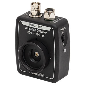
- Amplified Detectors
Customization options for the pulsed lasers include emission wavelength, optical output powers, and sub-nanosecond pulse widths.

| Posted Comments: | |
Andres Forrer
(posted 2023-01-10 08:05:20.923) Hi,
We are wondering if there would be an option with a linewidth below 10 kHz? And also, how the linewidth was measured. cdolbashian
(posted 2023-01-23 03:00:24.0) Thank you for reaching out to us. Unfortunately, at this time, we are unable to produce a laser with linewidth <10kHz. I have reached out to you directly to discuss the method with which we measure this specification. SHUNAN CHEN
(posted 2022-06-07 10:23:36.39) In the specifications, I didn't see the parameter about coherence length of the model TLX3, could you please provide me with a more detailed specification about this product? jdelia
(posted 2022-06-08 10:01:50.0) Thank you for contacting Thorlabs. For the TLX3 the coherence length will be 954 meters for 100 kHz. |