 Products Home / Optomechanical Components / Irises / Apertures / Iris Diaphragms / Ring-Actuated, SM-Threaded Iris Diaphragms
Ring-Actuated, SM-Threaded Iris Diaphragms
- Compatible with Our Lens Tubes
- Ring-Actuated Design Ideal for Low-Profile Applications
- Graduated and Zero Aperture Options
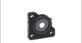
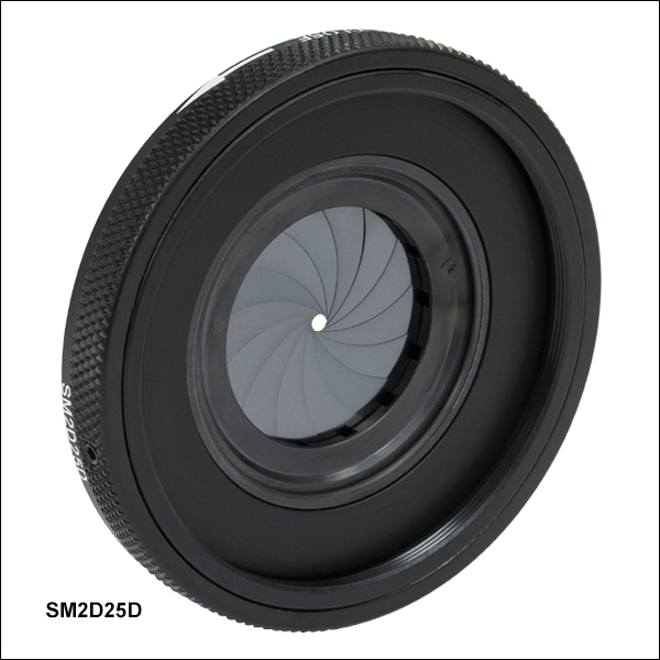
SM2D25D
SM2-Threaded Iris
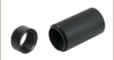
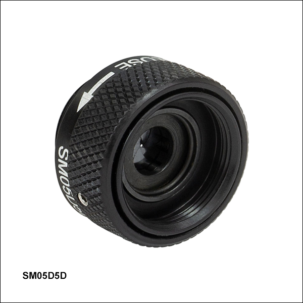
SM05D5D
SM05-Threaded Iris
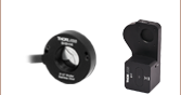
SM1D12C
SM1-Threaded,
Graduated Iris
Application Idea
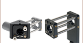
SM1D12D Iris in a 30 mm Cage System


Please Wait
Click to Enlarge
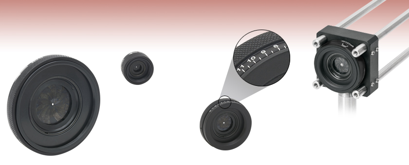
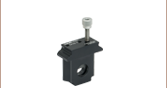
An XY Translation Mount can be used to optimize centration of an SM-threaded iris within a cage system.
| Iris Selection Guide |
|---|
| Post-Mountable Irises |
| Unmounted Irises |
| SM-Threaded Lever-Actuated Irises |
| SM-Threaded Ring-Actuated Irises |
| Cage System Irises |
| Motorized Irises |
Features
- SM05-, SM1-, SM2-, and SM3-Threaded Models
- Ring-Actuated Design Eliminates Actuating Lever, Significantly Reducing Clearance Requirements
- Versions with a Laser-Engraved Scale to Indicate Aperture Size
- Zero Aperture Option Blocks All Incoming Light in Closed Position
- Lockable via Setscrew on the Side of the Housing
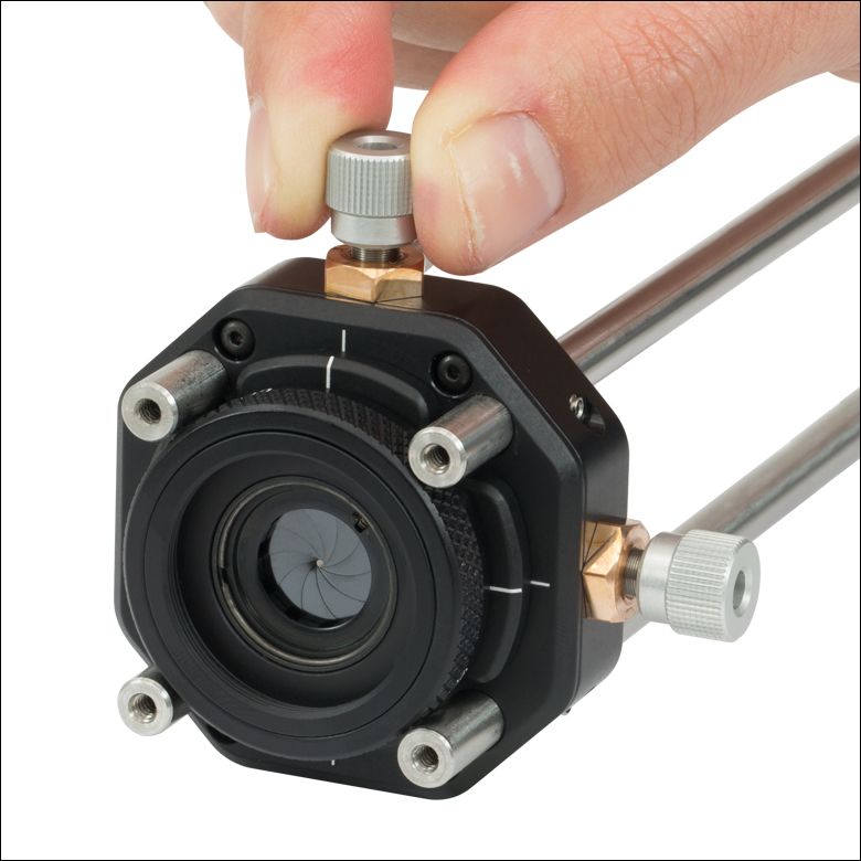
Our ring-actuated irises are perfect for tight spaces where the lever on our Standard Lever-Actuated Irises or Threaded Lever-Actuated Irises does not easily fit. Ring-actuated irises are especially beneficial within our cage assemblies, preventing interference between a lever actuator and the surrounding cage rods, as shown in the image to the right. The ring actuator provides an intuitive, smooth feel; the aperture size can be locked via a setscrew, see below for details. All of the irises on this page contain black spring steel leaves.
| Item # | SM05D5D | SM1D12D | SM1D12C | SM1D12CZ | SM2D25D | SM3D50D |
|---|---|---|---|---|---|---|
| Type | Ring Actuated | Ring Actuated | Ring Actuated, Graduated |
Ring Actuated, Graduated, Zero Aperture |
Ring Actuated | Ring Actuated |
| Thread Standard | SM05 (0.535"-40) | SM1 (1.035"-40) | SM1 (1.035"-40) | SM1 (1.035"-40) | SM2 (2.035"-40) | SM3 (3.035"-40) |
| Aperture (Min) | Ø0.6 mm (Ø0.02") | Ø0.8 mm (Ø0.03") | Ø1.0 mm (Ø0.04") | Ø0.0 mm (Ø0.00") | Ø1.4 mm (Ø0.05") | Ø2.5 mm (Ø0.10") |
| Aperture (Max) | Ø5.0 mm (Ø0.20") | Ø12.0 mm (Ø0.47") | Ø12.0 mm (Ø0.47") | Ø12.0 mm (Ø0.47") | Ø25.0 mm (Ø0.98") | Ø50.0 mm (Ø1.97") |

Insights into Aligning a Laser Beam
When installing a laser in an optical setup, it is good practice to start by leveling and orienting its beam so that it travels along a well-defined path. When the beam is prepared this way, not only is it easier to then divert the beam and route it through the optical elements in the system, but the results provided by tuning the system's alignment are more predictable and repeatable. The following sections describe how to:
- Level and Align the Laser Beam's Pointing Angle
- Divert the Beam and Align it to Follow a Desired Path
Click here for more Insights about lab practices and equipment.
Level and Align the Laser Beam's Pointing Angle
0:00 - Introduction
1:25 - Level and Align the Laser Beam's Pointing Angle
4:09 - Divert the Beam and Align it to Follow a Desired Path

Click to Enlarge
Figure 2: The beam can be aligned to travel parallel to a line of tapped holes in the optical table. The yaw adjustment on the kinematic mount adjusts the beam angle, so that the beam remains incident on the ruler's vertical reference line as the ruler slides along the line of tapped holes.
Click to Enlarge
Figure 1: Leveling the beam path with respect to the surface of an optical table requires using the pitch adjustment on the kinematic laser mount (Figure 2). The beam is parallel to the table's surface when measurements of the beam height near to (left) and far from (right) the laser's front face are equal.
Pitch (tip) and yaw (tilt) adjustments provided by a kinematic mount can be used to make fine corrections to a laser beam's angular orientation or pointing angle. This angular tuning capability is convenient when aligning a collimated laser beam to be level with respect to a reference plane, such as the surface of an optical table, and when aligning with respect to a particular direction in that plane, such as along a line of tapped holes in the table.
Before Using the Mount's Adjusters
First, rotate each adjuster on the kinematic mount to the middle of its travel range. This reduces the risk of running out of adjustment range, and the positioning stability is frequently better when at the center of an adjuster's travel range.
Then, make coarse corrections to the laser's height, position, and orientation. This can be done by adjusting the optomechanical components, such as a post and post holder, supporting the laser. Ensure all locking screws are tightened after the adjustments are complete.
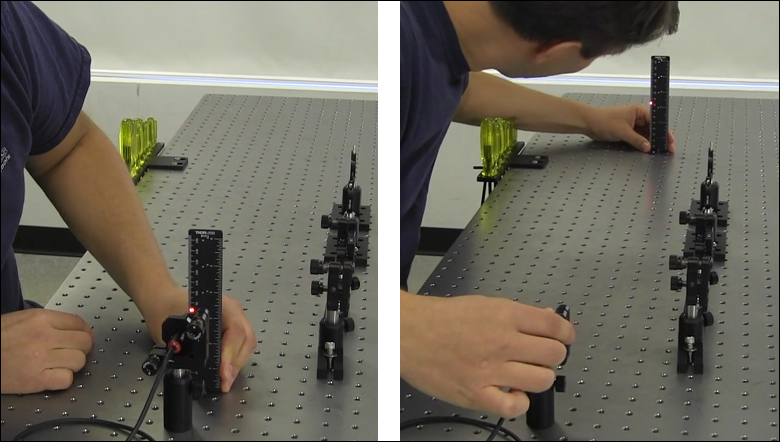
Level the Beam Parallel to the Table's Surface
Leveling the laser beam is an iterative process that requires an alignment tool and the fine control provided by the mount's pitch adjuster.
Begin each iteration by measuring the height of the beam close to and far from the laser (Figure 1). A larger distance between the two measurements increases accuracy. If the beam height at the two locations differs, place the ruler in the more distant position. Adjust the pitch on the kinematic mount until the beam height at that location matches the height measured close to the laser. Iterate until the beam height at both positions is the same.
More than one iteration is necessary, because adjusting the pitch of the laser mount adjusts the height of the laser emitter. In the video for example, the beam height close to the laser was initially 82 mm, but it increased to 83 mm after the pitch was adjusted during the first iteration.
If the leveled beam is at an inconvenient height, the optomechanical components supporting the laser can be adjusted to change its height. Alternatively, two steering mirrors can be placed after the laser and aligned using a different procedure, which is detailed in the section. Steering mirrors are particularly useful for adjusting beam height and orientation of a fixed laser.
Orient the Beam Along a Row of Tapped Holes
Aligning the beam parallel to a row of tapped holes in the table is another iterative process, which requires an alignment tool and tuning of the mount's yaw adjuster.
The alignment tool is needed to translate the reference line provided by the tapped holes into the plane of the laser beam. The ruler can serve as this tool, when an edge on the ruler's base is aligned with the edges of the tapped holes that define the line (Figure 2).
The relative position of the beam with respect to the reference line on the table can be evaluated by judging the distance between the laser spot and vertical reference feature on the ruler. Vertical features on this ruler include its edges, as well as the columns formed by different-length rulings. If these features are not sufficient and rulings are required, a horizontally oriented ruler can be attached using a BHMA1 mounting bracket.
In the video, when the ruler was aligned to the tapped holes and positioned close to the laser, the beam's edge and the ends of the 1 mm rulings coincided. When the ruler was moved to a farther point on the reference line, the beam's position on the ruler was horizontally shifted. With the ruler at that distant position, the yaw adjustment on the mount was tuned until the beam's edge again coincided with the 1 mm rulings. The ruler was then moved closer to the laser to observe the effect of adjusting the mount on the beam's position. This was iterated as necessary.
Divert the Beam and Align it to Follow a Desired Path
The first steering mirror reflects the beam along a line that crosses the new beam path. A second steering mirror is needed to level the beam and align it along the new path. The procedure of aligning a laser beam with two steering mirrors is sometimes described as walking the beam, and the result can be referred to as a folded beam path. In the example shown in the video above, two irises are used to align the beam to the new path, which is parallel to the surface of the optical table and follows a row of tapped holes.
Click to Enlarge
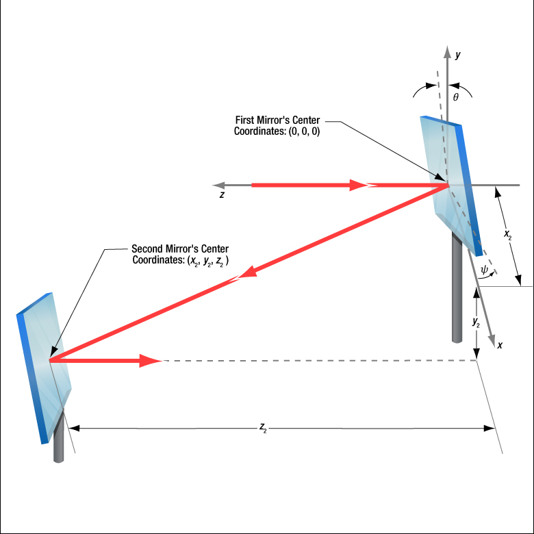
Figure 3: The beam reflected from Mirror 1 will be incident on Mirror 2, if Mirror 1 is rotated around the x- and y-axes by angles θ and ψ, respectively. Both angles affect each coordinate (x2 , y2 , z2 ) of Mirror 2's center. Mirror 1's rotation around the x-axis is limited by the travel range of the mount's pitch (tip) adjuster, which limits Mirror 2's position and height options.
Click to Enlarge
Figure 5: The adjusters on the second kinematic mirror are used to align the beam on the second iris.

Click to Enlarge
Figure 4: The adjusters on the first kinematic mirror mount are tuned to position the laser spot on the aperture of the first iris.
Setting the Heights of the Mirrors
The center of the first mirror should match the height of the input beam path, since the first mirror diverts the beam from this path and relays it to a point on the second mirror. The center of the second mirror should be set at the height of the new beam path.
Iris Setup
The new beam path is defined by the irises, which in the video have matching heights to ensure the path is level with respect to the surface of the table. A ruler or calipers can be used to set the height of the irises in their mounts with modest precision.
When an iris is closed, its aperture may not be perfectly centered. Because of this, switching the side of the iris that faces the beam can cause the position of the aperture to shift. It is good practice to choose one side of the iris to face the beam and then maintain that orientation during setup and use.
Component Placement and Coarse Alignment
Start by rotating the adjusters on both mirrors to the middle of their travel ranges. Place the first mirror in the input beam path, and determine a position for the second mirror in the new beam path (Figure 3). The options are notably restricted by the travel range of the first mirror mount's pitch (tip) actuator, since it limits the mirror's rotation (θ ) around its x-axis. In addition to the pitch, the yaw (tilt) of the first mirror must also be considered when choosing a position
After placing the second mirror on the new beam path, position both irises after the second mirror on the desired beam path. Locate the first iris near the second mirror and the second iris as far away as possible.
While maintaining the two mirrors' heights and without touching the yaw adjusters, rotate the first mirror to direct the beam towards the second mirror. Adjust the pitch adjuster on the first mirror to place the laser spot near the center of the second mirror. Then, rotate the second mirror to direct the beam roughly along the new beam path.
First Hit a Point on the Path, then Orient
The first mirror is used to steer the beam to the point on the second mirror that is in line with the new beam path. To do this, tune the first mirror's adjusters while watching the position of the laser spot on the first iris (Figure 4). The first step is complete when the laser spot is centered on the iris' aperture.
The second mirror is used to steer the beam into alignment with the new beam path. Tune the adjusters on the second mirror to move the laser spot over the second iris' aperture (Figure 5). The pitch adjuster levels the beam, and the yaw adjuster shifts it laterally. If the laser spot disappears from the second iris, it is because the laser spot on the second mirror has moved away from the new beam path.
Tune the first mirror's adjusters to reposition the beam on the second mirror so that the laser spot is centered on the first iris' aperture. Resume tuning the adjusters on the second mirror to direct the laser spot over the aperture on the second iris. Iterate until the laser beam passes directly through the center of both irises, as shown in the video. If any adjuster reaches, or approaches, a limit of its travel range, one or both mirrors should be repositioned and the alignment process repeated.
If a yaw axis adjuster has approached a limit, note the required direction of the reflected beam and then rotate the yaw adjuster to the center of its travel range. Turn the mirror in its mount until the direction of the reflected beam is approximately correct. If the mirror cannot be rotated, reposition one or both mirrors to direct the beam roughly along the desired path. Repeat the alignment procedure to finely tune the beam's orientation.
If a pitch axis adjuster has approached a limit, either increase the two mirrors' separation or reduce the height difference between the new and incident beam paths. Both options will result in the pitch adjuster being positioned closer to the center of its travel range after the alignment procedure is repeated.
| Posted Comments: | |
jiangli Yang
(posted 2023-06-29 09:47:22.643) Do you have any inventory? What is the minimum purchase quantity? What is the cost jdelia
(posted 2023-06-29 01:50:31.0) Thank you for contacting Thorlabs. In the future, please direct inquiries like this to your local sales team. Inventory and cost information can also be found directly on the product page on our website. We have also reached out to you directly to discuss the pricing and availability of these stock parts. user
(posted 2023-05-21 19:27:56.78) I was hoping for a graduated SM2 or 60 mm cage system iris. Are either of these likely to materialise in the near future? jdelia
(posted 2023-05-22 01:29:26.0) Thank you for contacting Thorlabs. While this is not something we currently have plans to release, I can certainly pass along your request to our design engineers via our internal suggestion forum for consideration as a future catalog item. Chris Hamley
(posted 2023-05-01 16:14:40.147) More a support question. I have one of these that someone before me disassembled and it is missing the screw linking the ring and the iris adjustment. What size and length is it? The smallest I have is a #2-56 which is clearly too big so I figure it is #1-72, #0-80, or metric. jdelia
(posted 2023-05-02 08:49:02.0) Thank you for contacting Thorlabs. The adjustment screw is M1.6 x 0.35 threaded and 9 mm long. Ben Carey
(posted 2022-11-30 17:49:52.467) Is there any guideline how much laser power this can handle? Are all the irises you offer the same material? ksosnowski
(posted 2022-12-01 12:34:11.0) Hello Ben, thanks for reaching out to Thorlabs. Unfortunately, we do not have a Damage Threshold for our iris diaphragms. It is difficult to specify the laser damage threshold because it depends on several parameters such as wavelength, iris opening, exposure duration, etc. If it helps, the maximum temperature that the blades can be heated would be around 250°C for the regular (black spring steel) irises and around 400°C for the stainless steel versions. I have reached out directly to discuss this application further. Justin Gerber
(posted 2021-10-14 15:38:41.55) Hello, can you please provide me the tolerance on the centration of the closed iris hole for these irises? Specifically SM1D12D? If the diaphragm is closed tightly the diaphragm "bows out" a little bit. Does the centration tolerance become worse in this circumstance? azandani
(posted 2021-10-27 03:03:29.0) Hello Justin, thank you for contacting Thorlabs. Based on the aperture, the tolerance of the closed iris hole will be around +/- 0.1 mm. In the circumstance where the iris "bows out", we unfortunately do not have a formal spec for how it would affect this tolerance spec. However, we do believe it will slightly affect it and we estimate that the tolerance would then be less than 0.2mm in this situation. Anton Ryzhov
(posted 2021-07-26 06:50:43.91) Dear Thorlabs team,
what is the axial distance between the leaves for Zero Aperture option? YLohia
(posted 2021-07-30 02:55:58.0) Thank you for contacting Thorlabs. Unfortunately, this is not a spec we can provide as the blades are in contact with each other most of the time (assuming you're referring to blade separation when you ask about axial distance). The blades are also hooked onto the spinning disk portion all at the same spot, so they overlap and touch each other at slightly varying angles, but are thin enough to slide over each other. The thickness of one blade is 0.05 mm (valid for all irises smaller than 50mm) and 0.07 mm (valid for irises equal and above 50mm in diameter). Chance Carter
(posted 2020-05-16 19:15:40.627) There has been a need for a long time now to develop a SM2D25D with a graduated iris (similar to the SM1D12C). I have grown weary of having to mark the SM2D25D with pencil marks. nreusch
(posted 2020-05-26 06:57:02.0) Thank you for your feedback. We will consider your suggestion and check whether we can add an SM2 graduated iris to our portfolio. anil
(posted 2018-08-31 04:29:48.37) I want to purchase this item kindly provide the quotation. wskopalik
(posted 2018-09-06 05:19:11.0) This is a response from Wolfgang at Thorlabs. Thank you very much for your inquiry.
I will contact you directly to provide a quotation. wayne.rapp
(posted 2018-03-08 13:27:51.94) Can you tell me an accuracy number that defines the location (concentricity) of the aperture vs. the mounting ring? mvonsivers
(posted 2018-03-09 06:55:50.0) This is a response from Moritz at Thorlabs. Thank you for your inquiry. I will contact you directly to provide information on tolerances of the iris diaphragm dimensions. franciscojavier.avila
(posted 2018-01-08 08:24:46.4) Hello:
I am coupling this variable iris in a rotating motor and I wanted to know the exact correspondence between angular displacement of the wheel and the diameter of the aperture.
Thanks
Francisco. swick
(posted 2018-01-09 04:06:17.0) This is a response from Sebastian at Thorlabs. Thank you for the inquiry. This parameter is not specified but we can provide typical data. I will contact you directly with further information. bdada
(posted 2012-06-05 19:04:00.0) Response from Buki at Thorlabs to kaccie:
Thank you for participating in our feedback forum. I am checking with our production team to see if this modification will negatively impact the performance of the iris. Please note that any modifications will void the warranty on the item.I have contacted you directly to continue this conversation. kaccie
(posted 2012-06-04 06:20:38.0) Regarding the SM1D12C. Would anything strange happen (in terms of proper movement of the blades) if I cut off the back 3 mm of the unit? I ask because the unit is just a bit too thick for my application, and I really don't need the SM1 threads sticking out in the back. Thanks
Kaccie jjurado
(posted 2011-06-16 11:13:00.0) Response from Javier at Thorlabs to k1w05: Thank you very much for contacting us. The distance from aperture plane to the outer face (with the external thread) is 4.14 mm. Keep in mind that your measured value of 4.54 mm is still within the mechanical tolerance range (+/-0.50 mm) of this dimension. Please contact us at techsupport@thorlabs.com if you have any further questions. k1w05
(posted 2011-06-12 09:33:47.0) I have a iris of SM1D12C. I want to design a structure to mount this iris, can you tell me the accurate distance between the apeture plane and one outer face of SM1D12C. The number I measured is about 4.54mm. I hope your accurate number. |

 Zoom
Zoom
Click to Enlarge
SM05D5D Mechanical Diagram
- SM05 (0.535"-40) Threaded on Both Sides
- Ring-Controlled, Ø0.6 mm - Ø5.0 mm Aperture
- Black Spring Steel Leaves
- Locking Setscrew with 0.035" (0.9 mm) Hex
The SM05D5D ring-actuated iris diaphragm is SM05-threaded for compatibility with our Ø1/2" lens tubes, 16 mm cage systems, and other SM05-threaded accessories. One side of the iris is externally threaded, while the other is internally threaded. This allows for easy insertion into existing systems using standard lens tube components. The design of this iris is well suited for integration into a cage system with minimal alignment. To precisely optimize the centration of the iris hole to the optical axis of the cage system, Thorlabs recommends mounting the iris on an XY Translation Mount.

 Zoom
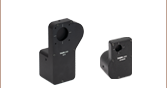
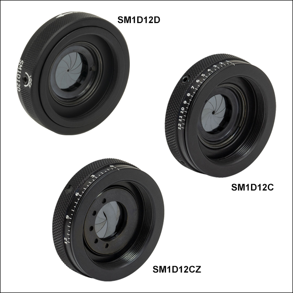
Zoom- SM1 (1.035"-40) Threaded on Both Sides
- Ring-Controlled, Ø12.0 mm Max Aperture
- Graduated and Zero-Aperture Versions Available
- Black Spring Steel Leaves
- Locking Setscrew with 0.05" (1.3 mm) Hex
These ring-actuated iris diaphragms are SM1-threaded for compatibility with our Ø1" lens tubes, 30 mm cage systems, and other SM1-threaded accessories. One side of the iris is externally threaded, while the other is internally threaded. This allows for easy insertion into existing systems using standard lens tube components. The design of these irises is well suited for integration into a cage system with minimal alignment. To precisely optimize the centration of the iris hole to the optical axis of the cage system, Thorlabs recommends mounting the iris on an XY Translation Mount.
The SM1D12D is our standard SM1-threaded, ring-actuated iris with a Ø12.0 mm maximum aperture. Thorlabs also offers the CP20D Iris for 30 mm Cage Systems which is integrated into a cage plate for direct mounting to cage rods.
The SM1D12C Graduated Iris offers an additional laser-engraved scale, which indicates the actual diameter of the iris in millimeters to within ±0.5 mm. In applications where the iris cannot be easily viewed, such as the lens tube configuration shown in Figure 366D, this engraved scale greatly simplifies the process of optimizing the iris diameter.
The SM1D12CZ Zero-Aperture Graduated Iris provides the added benefit of being able to close completely. Our zero-aperture design achieves a completely closed aperture by utilizing two sets of steel leaves mounted in two adjacent planes. When the ring is in the closed position, the iris aperture is completely closed (zero aperture), unlike a standard iris, which has a non-zero diameter aperture when in the minimum position. Please note that as the aperture gets smaller, it also becomes slightly elliptical due to the design of the iris.
Click to Enlarge
Figure 366A SM1D12D Mechanical Diagram
Click to Enlarge
Figure 366B SM1D12C Mechanical Diagram
Click to Enlarge
Figure 366C SM1D12CZ Mechanical Diagram

Click for Details
Figure 366D SM1D12C Shown Between Two SM1 Lens Tubes

 Zoom
Zoom
Click to Enlarge
SM2D25D Mechanical Diagram
- SM2 (2.035"-40) Threaded on Both Sides
- Ring-Controlled, Ø1.4 mm - Ø25.0 mm Aperture
- Black Spring Steel Leaves
- Locking Setscrew with 0.05" (1.3 mm) Hex
The SM2D25D ring-actuated iris diaphragm is SM2-threaded for compatibility with our Ø2" lens tubes, 60 mm cage systems, and other SM2-threaded accessories. One side of the iris is externally threaded, while the other is internally threaded. This allows for easy insertion into existing systems using standard lens tube components. The design of this iris is well suited for integration into a cage system with minimal alignment. To precisely optimize the centration of the iris hole to the optical axis of the cage system, Thorlabs recommends mounting the iris on an XY Translation Mount.
Thorlabs also offers the LCP50D Iris with a Ø2.0 mm to Ø50.0 mm aperture for 60 mm Cage Systems which is integrated into a cage plate for direct mounting to cage rods.

 Zoom
Zoom
Click to Enlarge
SM3D50D Mechanical Diagram
- SM3 (3.035"-40) Threaded on Both Sides
- Ring-Controlled, Ø2.5 mm - Ø50.0 mm Aperture
- Black Spring Steel Leaves
- Locking Setscrew with 0.05" (1.3 mm) Hex
The SM3D50D ring-actuated iris diaphragm is SM3-threaded for compatibility with our Ø3" lens tubes and other SM3-threaded accessories. One side of the iris is externally threaded, while the other is internally threaded. This allows for easy insertion into existing systems using standard lens tube components. The design of this iris is well suited for integration into a cage system with minimal alignment.