 Products Home / Technical Resources / Insights / Device Behavior Insights / Position a Pair of Steering Mirrors Using Reflection Calculations
 Position a Pair of Steering Mirrors Using Reflection Calculations


Please Wait
What is the required spacing between two beam-steering mirrors?
The required separation between two steering mirrors (Figure 1) depends on the slope of the beam reflected from the first mirror and the height difference between the two mirrors. Knowing the needed spacing can be important for blocking out space for a setup on a breadboard or optical table.
While it is tempting to perform a quick calculation using just the first mirror's pitch (tip) with respect to the incident beam, omitting the yaw (tilt) can result in a significant underestimate of the mirrors' required separation. In the following example, the spacing is calculated using the assumption that the entire mount is rotated around the post axis to provide yaw, while the mount's adjuster provides pitch (Figure 2). This approach is often used to initially position mirrors.
Click to Enlarge
Figure 2: Instead of using the yaw adjuster, the entire mount is often rotated around the post axis (left) to provide yaw during initial positioning. This rotates the mount with respect to the global x-, y-, z-axes and the incident beam. The mount's pitch adjuster tunes the mirror's pitch (right), changing the mirror's orientation with respect to the mount's x'-, y'-, and z'-axes. The above images show a KS2 mirror mount and a RMC position-maintaining collar.
Click to Enlarge
Figure 1: The first mirror reflects the incident beam towards the second mirror. The required spacing between the two depends on both the pitch and yaw of the first mirror. These KM100 mirror mounts have adjusters that can tune pitch and yaw over a ±4° range.
Click to Enlarge
Figure 4: These values were calculated using the setup described in Figure 3, except that a 1° pitch angle was assumed for the first mirror. These results demonstrate that decreasing the pitch increases the required separation between the first and second mirrors. However, this may be acceptable since stability improves when the adjusters are not extended to the limits of their travel ranges.
Click to Enlarge
Figure 3: In this example, the goal is to position the second mirror on the table, so that it intercepts the reflected beam when it is 0.5" lower (y2 = -0.5") than the incident beam. It is assumed the pitch on the first mirror is 4°, the maximum the mount's adjuster can provide. The entire mount is rotated around the post axis to change the first mirror's yaw. The mount's yaw adjuster is not used, since yaw angles >4° are of interest and this step does not involve fine-tuning the mirror's orientation.
Click to Enlarge
Figure 5: This plot views the table's surface from above, with the first mirror (star) at the origin. Curves labeled in the legend identify a few options for positioning a second mirror on the table to intercept the beam at a height (y2) that is 0.5" lower than at the first mirror. The required separation increases significantly as the first mirror's yaw angle increases, even when its pitch angle is held constant.
Applying Yaw and Pitch
Positioning beam steering mirrors is typically a two-step process. First the mirrors are placed in position and roughly oriented, then their orientations are finely tuned.
This example considers the first step and assumes different methods are used to adjust pitch and yaw. Since the required yaw angle is often too large for the mount's adjuster to provide, yaw is frequently provided by rotating the entire mount around the post axis (Figure 2, left). This changes the incident beam's angle with respect to the mount. Although the mount's yaw adjuster is not used, the pitch adjuster is used. It alters the orientation of the mirror with respect to both the incident beam and the rest of the mount (Figure 2, right).
The mirror's orientation is typically fine-tuned using the mount's pitch and yaw adjusters, without rotating the mount around the post axis. Using both adjusters has a different effect on the mirror's orientation than the approach described in this example.
Points on the Reflected Beam
The first mirror's center is chosen as the origin of a fixed Cartesian coordinate system (Figure 2). The z-axis points back towards the source and is parallel to the incident beam. The y-axis is vertical and perpendicular to the table.
When the angles of rotation around the post and x'-axes are known ( and θ, respectively), points
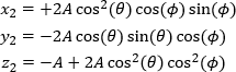 .
.
The variable A is a scaling factor: the larger its value, the larger the distance between the point and the mirror. In this example, the change in height (y2 ) is known and used to calculate values of x2 and z2 .
Example: Setting up Steering Mirrors
These equations can be useful when positioning a pair of steering mirrors, which are used to change beam height and direction. The center of the first mirror is set at the height of the incident beam, and the center of the second mirror is set at the height of the new beam path. The second mirror must intercept the reflected beam when its height equals that of the new beam path.
For this example, both beam paths are parallel to the optical table, but the new beam path is 0.5" lower than the incident beam path. The mirrors are secured in KM100 kinematic mounts, which are attached to the tops of posts secured in post holders (Figure 1). The mounts' pitch and yaw adjusters each have a limited ±4° tuning range, which is adequate for setting the initial pitch, but not yaw, of the mirror. The yaw between the incident beam and mirror is instead changed by rotating the entire mount around the post axis, which effectively eliminates the yaw tuning range limit.
Potential x2 and z2 coordinates of the second mirror are plotted in Figure 3 for different yaw angles of the first mirror. These values were calculated using the desired height change of the new beam path
Figure 5 plots the x2 and z2 coordinates of the second mirror as positions on the optical table. The perspective is from a point directly above the table, the first mirror's position is marked by a star, and the gray circles (guides for the eye) are concentric around it. The arrows indicate selected directions of the reflected ray, each corresponding to a different yaw angle. The curves labeled in the legend were calculated for different pitch angles and a constant -0.5" change in beam height. Comparing the curves with the gray circles illustrates that the necessary separation between the two mirrors increases significantly as the yaw angle increases. Larger separations are also required when the pitch angle is reduced.
Want additional Insights on beam alignment?
Watch the full video.
|
Looking for more Insights? |
Date of Last Edit: Jan. 5, 2021 |
| Posted Comments: | |
| No Comments Posted |