 Products Home / Technical Resources / Beam Characterization Tutorials / Fabry-Perot Interferometer Tutorial
Fabry-Perot Interferometer Tutorial

Please Wait

Scanning Fabry-Pérot Interferometers
Fabry-Pérot interferometers are optical resonators used for high-resolution spectroscopy. With the ability to detect and resolve the fine features of a transmission spectrum with high precision, these devices are commonly used to determine the resonant modes of a laser cavity, which often feature closely-spaced spectral peaks with narrow linewidths.
Spatial Mode Structure
Click to Enlarge
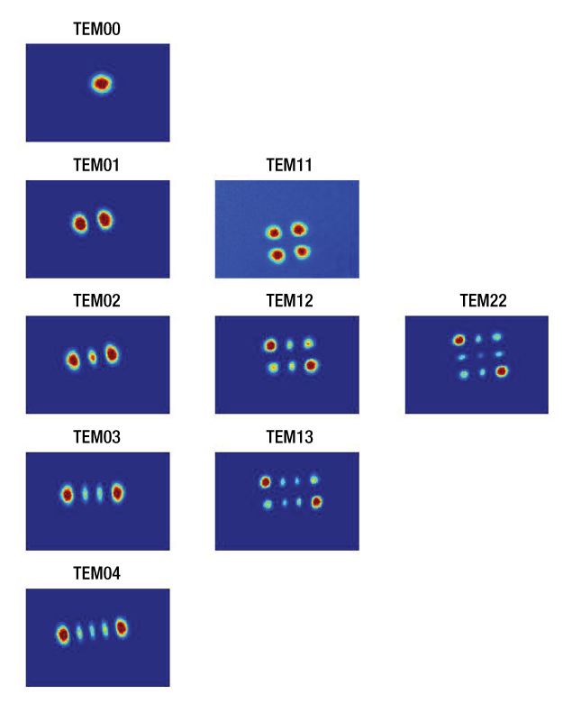
Figure 42A Spatial mode structure for lowest-order TEM modes. Figure reproduced from Further Development of NICE-OHMs.2
The most common configuration of a Fabry-Pérot interferometer is a resonator consisting of two highly reflective, but partially transmitting, spherical mirrors that are facing one another. This type of resonator can be fully characterized by the following set of parameters:
- the resonator length or mirror spacing, L
- the radii of curvature of the input and output mirror, R1 and R2, respectively
- the transmission, reflection, and loss coefficients of the input and output mirror, t1,2, r1,2, and l1,2, respectively, related to each other in such a way that t1,2 + r1,2 + l1,2 = 1 is fulfilled
Light waves entering the resonator through the input mirror will, depending on the mirror reflectivity, travel a large number of round-trips between the two mirrors. During this time, the waves also undergo either constructive or destructive interference. Constructive interference reinforces the wave and builds up an intracavity electric field. This corresponds to the case where a standing wave pattern is formed between the resonator mirrors, which occurs when the resonator length L is equal to an integer multiple of half the wavelength, qλ/2. All other wavelengths that do not fit this criteria are not supported by the resonator and destructively interfere.
By assuming a general Gaussian beam solution to the paraxial wave equation, it can be shown1 that only the following frequencies, νqmn, can exist inside the resonator:

where q, m, and n are mode numbers that can take on positive integers or zero and c is the speed of light. The g-parameters of the resonator g1,2 are given by
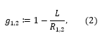
where R1,2 > 0 for concave mirrors and R1,2 < 0 for convex mirrors. These frequencies are referred to as Gaussian transverse electromagnetic (TEM) modes of order (m,n), or the Hermite-Gaussian modes, and are typically denoted as TEMm,n. The mode numbers m and n are associated with transverse modes, which describe the intensity pattern perpendicular to the optical axis, while q corresponds to the longitudinal mode. The TEM00 modes with m = n = 0 are called the fundamental TEM modes, or longitudinal modes, while TEM modes with m,n > 0 are called higher-order TEM modes. Figure 42A shows the spatial intensity pattern for a number of modes. Indices m and n correspond to the number of nodes in the vertical and horizontal directions respectively. For the case of light in the near-infrared region, the parameter q is on the order of 106. The g-parameters of a resonator are often found in the so-called stability criterion. A resonator is called stable when its g-parameters fulfill the condition 0 ≤ g1g2 ≤ 1.1
Transmission Spectrum of a Fabry-Pérot Interferometer
Click to Enlarge
Figure 42B Mode spectrum of a Fabry-Pérot interferometer for mirror reflectances of 99.7%, 80%, and 4%, illustrated by a blue, red, and green curve, respectively. 99.7% reflectance corresponds to the case for the SA200 series, which has a free spectral range of 1.5 GHz. The 4% reflectance corresponds to a typical "fringing effect" arising from reflections between parallel surfaces on glass plates.
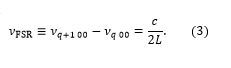
For the case where light is spatially mode matched to the fundamental TEM00 mode, i.e., when the wave fronts of the Gaussian beam perfectly match with the mirror surfaces and the incoming beam is aligned to the optical axis of the resonator, no higher order modes (m,n > 0) are evoked. The transmission spectrum of the resonator consists only of TEM00 modes that differ from each other by different values of the parameter q. The distance between two consecutive TEM00 modes νq00 and νq+1 00 is called the free spectral range (FSR) of the resonator and is given by
This equation holds for all linear resonators comprised of two mirrors. The transmission intensity of a resonator, It, as a function of the frequency detuning from mode q,
Δνq = ν - νq, is given by the well-known Airy-formula3
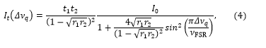
where I0 is the intensity of the light incident on the instrument and all other variables are as described above. Figure 42B shows the typical transmission spectrum of a Fabry-Pérot interferometer. From the above equation it can be seen that the on-resonance transmission, Tcres, is given by
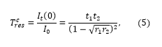
which also makes clear that the on-resonance transmission not only depends on the transmission of a single mirror, but also on the mirror's reflection and loss coefficients, since all mirror coefficients are connected through t1,2 + r1,2 + l1,2 = 1 by definition. One always strives to keep absorption losses as small as possible to obtain maximum transmission for a given set of r1,2.
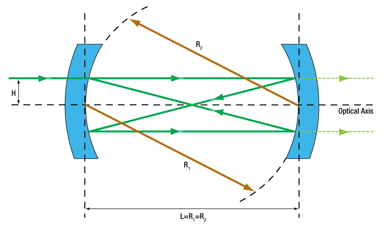
It can be seen from Equations (1) and (2) that the position of higher order transverse modes strongly depends on mirror spacing, L, and the radii of curvature of the mirrors, R1,2. For the special case when the two mirrors have the same radius, i.e. R1 = R2 = R, and the distance between the mirrors is equal to the mirror radius, i.e. L= R, the resonator is called a confocal resonator. Figure 42C shows a typical ray trace for a beam entering the resonator parallel to the optical axis at a distance H. All Thorlabs Fabry-Pérot interferometer models are based on such a confocal resonator design. For such a configuration, Equation (1) above simplifies to
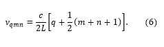
Two important conclusions can be drawn from this equation. First, all modes are degenerate, i.e., there exist higher order TEM modes that share the same frequency as the fundamental TEM00 (e.g. TEMq' 00, TEMq'-1 02, TEMq'-1 11, TEMq'-1 20, TEMq'-2 40, TEMq'-2 31, TEMq'-2 22, … all share the same frequency). Second, the spectrum shows a regular, equidistant mode structure and the spacing between two consecutive modes is given by c/4L. If special care is not taken to obtain spatial mode matching, it is highly unlikely that higher order modes are suppressed. As a result, several higher order modes exist between two consecutive fundamental modes (TEMq00 and TEMq+1 00) and the equidistant spacing between modes makes it appear that this FSR is equal to c/4L. To account for the existence of higher order modes, all values given for the FSR of the Thorlabs Fabry-Pérot interferometers are referring to the so-called confocal free spectral range, νFSR,conf = c/4L. The arrows in Figure 42D highlight the difference between νFSR and νFSR,conf. With careful alignment along the resonator's optical axis and near-perfect spatial mode matching of the incident light, it is possible to extinguish every other mode in the spectrum. Figure 42D below shows a configuration with near perfect mode matching. Higher order modes still exist, but they are smaller than the fundamental modes. Further tweaking of the alignment will eventually distinguish every other mode in the spectrum.
Click to Enlarge
Figure 42C Schematic of a confocal Fabry-Pérot resonator. Mirrors with radius R1 = R2 (brown arrows) are separated by a distance L that is equal to the mirror radius. The solid green lines show a ray-trace of an off-axis input beam entering the resonator at a height H. The dashed light green lines represent the beam transmitted through the second mirror; light transmitted through the first mirror is not pictured.
Click to Enlarge
Figure 42D Spectrum of a confocal resonator with near perfect spatial mode matching, where every other mode is extinguished as only the fundamental mode is excited. The TEMqmn labels represent only one mode contained at that particular frequency; all modes are degenerate and, as described in the text, there are other modes sharing the same frequency.
Finesse and Mode Width (Resolution)
Click to Enlarge
Figure 42E When two Lorentzian lineshapes are separated by their FWHM, they meet the Rayleigh criteria for being resolvable.
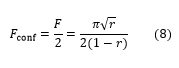
A Fabry-Pérot interferometer's performance, to a large extenta, depends on the mirror reflectivity. Low-reflectivity mirrors will yield broader transmission peaks, while high-reflectivity mirrors will yield narrower transmission peaks. The mirror reflectivity plays a significant role in how well the interferometer can distinguish features of the transmission spectrum. Beyond the free spectral range, two more important quantities of a Fabry-Pérot interferometer are its finesse and mode width. The finesse, F, for mirrors having identical reflection coefficients, r, is given by
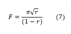
For the case of a confocal interferometer, it can sometimes be convenient to express the finesse as
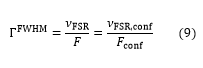
An interferometer with a higher finesse will produce narrower transmission peaks than one with a lower finesse. Thus, a higher finesse increases the resolution of the interferometer, allowing it to more easily distinguish closely spaced transmission peaks from one another. According to the Rayleigh criterion (see Figure 42E), two identical Lorentzian line shapes are resolvable when the peaks are separated by the full width at half maximum (FWHM) of each peak, denoted as ΓFWHM. The FWHM mode width, also called resolution, is related to the finesse and the FSR of a confocal resonator by
which is a measure of the minimum allowed spacing between two peaks to be resolved. For example, an interferometer with an FSR of 1.5 GHz and a finesse of 250 will have a FWHM of 6 MHz, and thus it will be able to distinguish features of the transmission spectrum as long as the peak values are at least 6 MHz apart. For visible light, this corresponds to a wavelength resolution of about 10 fm (10-14 m).
Thorlabs offers mirrors with crystalline coatings that achieve 99.999% reflection at 1550 nm, which equates to a reflection coefficient of 0.99999 or a finesse of 314 158. An interferometer using these crystalline mirrors would have a resolution of approximately 4.8 kHz, four orders of magnitude finer than the previous example, given the same FSR of 1.5 GHz.
Further Considerations on the Finesse
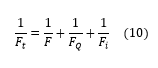
In fact, a measured finesse has a number of contributing factors: the mirror reflectivity finesse, simply denoted F above, the mirror surface quality finesse FQ, and the finesse due to the illumination conditions (beam alignment and diameter) of the mirrors Fi. The overall finesse of a system, Ft, is given by the relation4
Often, the reflectivity finesse, Equation (8), is presented as an effective finesse, which is true for the case when the other contributing factors are negligible. For Thorlabs' interferometers, the reflectivity finesse dominates when operating with proper illumination.b
The second term in Equation (10) involves, FQ, which accounts for mirror irregularities that cause a symmetric broadening of the lineshape. The effect of these irregularities is a random position-dependent path length difference that blurs the lineshape. The manufacturing process that is used to produce the cavity mirror substrates always has to ensure that the contribution from FQ is negligible in comparison to the specified total finesse of a resonator; in other words, the substrates surface figure should never be the limiting factor for the finesse.
The final term in Equation (10), which deals with the illumination finesse, Fi, will reduce the resolution as the beam diameter is increased or as the input beam is offset. When the finesse is limited by the Fi term, the measured lineshape will appear asymmetric. The asymmetry is due to the path length difference between an on-axis beam and an off-axis beam, resulting in different mirror spacings to satisfy the maximum transmission criteria.
To quantify the effects of the variable path length on Fi, consider an ideal monochromatic input, a delta function in wavelength with unit amplitude, entering the Fabry-Pérot cavity coaxial to the optic axis and having a beam radius a. The light entering the interferometer at H = +e, where e is infinitesimally small but not zero, will negligibly contribute to a deviation in the transmitted spectrum. Light entering the cavity at H = +a will cause a shift in the transmitted output spectrum, since the optical path length of the cavity will be less by an approximate distance of a4/R3. Assuming the input beam has a uniform intensity distribution, the transmitted spectrum will appear uniform in intensity and broader due to the shifts in the optical path length. As a result, the wavelength input delta function will produce an output peak with a FWHM of H4/R3 (Ref. 6).
Click to Enlarge
Figure 42F The total finesse Ft as a function of beam diameter, 2H, for the SA200 and SA210 Fabry-Pérot Interferometers using Equation (12). The finesse is calculated for a wavelength λ of 633 nm.
Assuming that only Fi contributes significantly to the total finesse, then Eq. (9) can be used to calculate Fi for the idealized input beam. Substituting λ/4 for the FSR, and (H4/R3) for FWHM, yields:
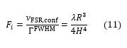
The λ/4 substitution for the FSR is understood by considering that the cavity expands by λ/4 to change from one longitudinal mode to the next. For an input beam with a real spectral distribution, the effect of the shift will be a continuous series of shifted lineshapes. It should be noted that the shift is always in one direction, leading to a broadened or asymmetric lineshape due to the over-sized or misaligned beam.
Now, the total finesse for the case of high reflectivity mirrors (r ≈ 1) can be found using Equation (10), which includes significant contributions from both F and Fi (Note: Fq is still considered to have a negligible effect on Ft):
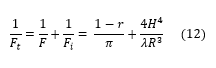
Equation (12) is used to provide an estimate, in general an overestimate, of beam diameter effects on the total finesse of a Fabry-Pérot Interferometer, and several assumptions have been made. The first assumption is that the diameter of the beam is the same as the diameter of the mirror. In practice, the diameter of the beam is typically significantly smaller than that of the mirror, which also helps to reduce spherical aberration.5 A second assumption is that the light is focused down to an infinitesimally small waist size. Even for monochromatic light, the minimum waist size is limited by diffraction, and in multimode applications the waist size can be quite large at the focus. Figure 42F provides a plot of Equation (12) evaluated at 633 nm for the SA200 and SA210 Fabry-Pérot Interferometers, which have cavity lengths of 50 mm and 7.5 mm respectively. The traces in the plot assume that the reflectivity finesse is equal to 250 for the SA200 and 180 for the SA210, which are typical values obtained for mirrors used in our interferometers.
Cavity Ring-Down Time and Intracavity Power Build-Up
As a light wave travels many round-trips inside the resonator, the light is stored inside for a certain amount of time, and only a small portion of its energy leaks out as it impinges on either the input or the output mirror. In other words, the light wave has a certain life-time inside the resonator. This time is called the cavity ring-down time or cavity storage time, τcav, and is given by
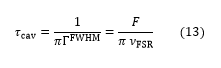
This relation can show that τcav increases with the cavity finesse, i.e., the higher the finesse and the mirror reflectivity, the longer light is stored inside the resonator. In-line with this, another important quantity is the so-called intracavity power build-up, defined by the ratio of the intracavity intensity, Ic, and the incident intensity according to
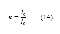
which is given by F/π for an impedance-matched cavity (i.e., with a vanishing on-resonance reflection). This relates the intracavity intensity to the finesse by
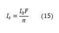
The fact that the power stored inside the cavity increases with finesse has to be kept in mind, when beams with high incident power are evaluated with a Fabry-Pérot interferometer.
Spectral Resolving Power and Étendue
The spectral resolving power of an interferometer is a metric to quantify the spectral resolution of an interferometer, and is an extension of the Rayleigh criterion. The spectral resolving power, SR, is defined as:
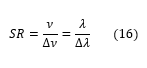
where ν is the frequency of light and λ is its wavelength. It can be shown that for a confocal Fabry-Pérot interferometer, the SR is given by:
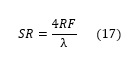
where F is the finesse of the interferometer, R is the radius of curvature of the mirrors, and λ is the wavelength. However, to achieve this maximum instrumental profile while the interferometer is in scanning mode, the aperture of the detector would need to be infinitesimally small; as the size of the aperture is increased, the spectral resolving power begins to decrease. The spectral resolving power must be balanced with the étendue of the interferometer. The étendue (U) is the metric for the net light-gathering power of the interferometer. When the light source is a laser beam, the étendue provides a measure of the alignment tolerance between the interferometer and the laser beam. The étendue is defined as the product of the maximum allowed solid angle divergance (Ω) and the maximum allowed aperture area (A). For the confocal system, the étendue is given by:
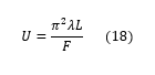
where F is the finesse of the interferometer, λ is the wavelength, and L is the mirror spacing. The spectral resolving power and étendue need to be balanced for the interferometer to work correctly. The accepted compromise for this balance is to increase the mirror aperture until the the spectral resolving power is decreased by 70% (0.7*SR) (Ref. 4). Under this condition the "ideal" étendue becomes π2λR/F, where R is the mirror's radius.
For more information on our Fabry-Pérot interferometers, including typical application examples, please see the full web presentation here.
References
- P. W. Milonni and J. H. Eberly, Lasers (John Wiley & Sons, Inc., 1988) p. 302.
- P. Ehlers, Further Development of NICE-OHMS, Ph.D. thesis, Umeå University, Sweden, 2014.
- D. Romanini et al., in Cavity-Enhanced Spectroscopy and Sensing, edited by G. Gagliardi and H.P. Loock (Springer, 2014), Vol. 179, Chap. 1, pp. 1 - 60.
- M. Hercher, "The Spherical Mirror Fabry-Perot Interferometer," Applied Optics, vol. 7, no. 5, pp. 951 - 966, 1968.
- J. Johnson, "A High Resolution Scanning Confocal Interferometer," Applied Optics, vol. 7, no. 6, pp. 1061 - 1072, 1968.
- W. Demtröder, Laser Spectroscopy, Vol. 1: Basic Principles, (Springer, 2008) p. 152.
Footnotes
- It can be seen from Equation (1) above, that the optical path length and subsequently the free spectral range, finesse, and mode width depend on the beam offset, h, from the optical axis of the interferometer. Hence, best performance is achieved for the beam being well aligned to the optical axis. Also, the radius of curvature of the Gaussian beam impinging on the interferometer should equal the radius of curvature of the mirrors on the corresponding reflective surface. Provided a well collimated beam, this can be achieved sufficiently well by following the lens recommendations in the Alignment Guide tab on our full Fabry-Pérot Interferometers web presentation.
- The reflective coatings in all Thorlabs Fabry-Pérot interferometers have been designed so that the minimum F is better than 1.5 times the minimum specified finesse across their entire operating wavelength range for each model.
| Posted Comments: | |
| No Comments Posted |