 Products Home / Optical Elements / Optical Filters / Spectral Filters / Hard-Coated Edgepass Filters
Hard-Coated Edgepass Filters

- High-Performance Longpass and Shortpass Filters
- OD > 5 in Rejection Region
- Transmission > 85% in Transmission Region
- Hard-Coated Dielectric Coating on UV Fused Silica
Transmission Direction Indicator
FKLPVIS
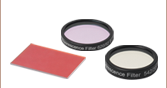
Hard-Coated Visible Longpass Filter Kit
FELH0700
Longpass
Cut-On: 700 nm
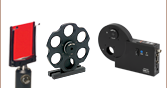
FELH0650 Longpass Filter in a CFH2 Filter Holder
(Mounts and Assemblies Sold Separately)
FESH05750
Shortpass
Cut-Off: 750 nm


Please Wait
Packaging Redesign
Thorlabs is investing in green initiatives to replace plastic and foam optics packaging with more sustainable solutions. Leave feedback or learn more about what went into the design of our pilot program for Ø1" single optics here.

Click to Enlarge
Our new case is made from recyclable steel and includes recyclable paper inserts to protect the optic inside.
 Click to Enlarge
Figure 1.1 Ø1" Bandpass Filter Drawing
| Available Wavelengths | |
|---|---|
| Longpass Filters |
350 - 700 nm |
| 725 - 975 nm | |
| 1000 - 1300 nm | |
| 1350 - 2000 nm | |
| Shortpass Filters |
450 - 700 nm |
| 750 - 1100 nm | |
| Longpass Filter Kit | |
| Shortpass Filter Kit | |
Features
- 12.5 mm or 25.0 mm Outer Diameter
- Longpass and Shortpass Filters
- Excellent Suppression in Rejection Region (OD > 5)
- Recommended Transmission Direction Engraved on Edge
- Filter Kits Containing 10 Hard-Coated Longpass or Shortpass Filters
- Ideal as Raman Spectroscopy Filters or Emission Filters for Fluorescence Applications
- Custom Edgepass Filter Sizes are Available by Contacting Tech Support
Thorlabs' Hard-Coated Edgepass Filters are high-performance filters that are very useful for isolating regions of a spectrum. These filters offer an optical density (OD) in excess of 5 in the rejection region and greater than 85% transmission in the transmission region. Please see the Specs tab for more information on the rejection and transmission regions for these filters. For damage threshold specifications on select filters, please see Tables G1.1 through G9.1.
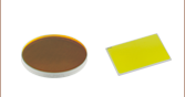
These edgepass filters feature durable, hard-coated dielectric coatings on UV fused silica. The film construction is essentially a modified quarter-wave stack, using interference effects to isolate spectral bands (see the Specs tab for transmission information). The dense coating on these filters allows them to be constructed using a single substrate, which yields a stable, long-lasting filter. This coating can withstand the normal cleaning and handling necessary when using any high-quality optical component. Please see the Comparison tab for information about the advantages of hard-coated filters compared to soft-coated filters, such as increased durability and transmission performance.
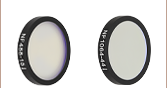
Each filter is housed in a black anodized aluminum ring that is labeled with an arrow indicating the design propagation direction. The ring makes handling easier and enhances the blocking OD by limiting scattering. These filters can be mounted in our extensive line of filter mounts and wheels. As the mounts are not threaded, Ø1" retaining rings will be required to mount the filters in one of our internally-threaded SM1 lens tubes. We do not recommend removing the filter from its mount as the risk of damaging the filter is very high.
These longpass and shortpass filters are also available in kits.
| Table 2.1 Specifications | ||||
|---|---|---|---|---|
| Longpass | Shortpass | |||
| Diameter | Ø12.5 mm | Ø25.0 mm | Ø12.5 mm | Ø25.0 mm |
| Transmission Region | See Table 2.2 | See Table 2.3 | ||
| Transmission | >90% (Absolute)a | |||
| Cut-on or Cut-off Tolerance | ±0.75% | <0.75% of Cut-off λ | ||
| Rejection Region | See Table 2.2 | See Table 2.3 | ||
| Optical Density (OD) in Rejection Region | OD > 5 (Absolute) | |||
| Transmitted Wavefront Error | ≤158.2 nm RMS Over Clear Aperture | λ/4 at 632.8 nmb | ≤158.2 nm RMS Over Clear Aperture | λ/4 at 632.8 nmb |
| Slope Tolerancec | <1.0% | |||
| Construction | Hard-Coated Dielectric on UVFS Substrate | |||
| Surface Quality | 60-40 Scratch-Dig | 40-20 Scratch-Dig | 60-40 Scratch-Dig | 40-20 Scratch-Dig |
| Substrate Material | UV Fused Silicad | |||
| Diameter | 25.0 mm (0.98") | |||
| Clear Aperture | Ø≥10.0 mm (Ø0.39") | Ø21.1 mm (Ø0.83") | Ø≥10.0 mm (Ø0.39") | Ø21.1 mm (Ø0.83") |
| Thickness | 3.5 mm (0.14") | |||
| Substrate Thickness | 2 mm (0.08") | |||
| Table 2.3 Hard-Coated Shortpass Filters |
|---|
Click for Details
Figure 2.4 The slope tolerance is defined as the percentage of the cut-on or cut-off wavelength required to transition from an OD of 5 (T ~ 0.001%) to 50% transmission (OD ~ 0.3). In this case, the slope tolerance is quoted as <1%, and this data set shows a span of approximately 6 nm from an OD of 5 to 50% transmission.
| Table 2.2 Hard-Coated Longpass Filters |
|---|
Optical Density Equation:![]()
| Table 3.1 Damage Thresholds Specifications | |
|---|---|
| Item # | Damage Threshold |
| FELH05550 FELH0550 |
1.0 J/cm2 (532 nm, 10 ns, 10 Hz, Ø0.472 mm) |
| FELH05950 FELH0950 |
0.25 J/cm2 (1064 nm, 10 ns, 10 Hz, Ø1.010 mm) |
| FELH051000 FELH1000 |
3.75 J/cm2 (1064 nm, 10 ns, 10 Hz, Ø0.516 mm) |
| FELH051050 FELH1050 |
0.1 J/cm2 (532 nm, 10 ns, 10 Hz, Ø0.360 mm) |
| FESH05600 FESH0600 |
3 J/cm2 (1064 nm, 10 ns, 10 Hz, Ø0.429 mm) |
| FESH05700 FESH0700 |
1.0 J/cm2 (532 nm, 10 ns, 10 Hz, Ø0.472 mm) |
| FESH051000 FESH1000 |
7.5 J/cm2 (1064 nm, 10 ns, 10 Hz, Ø0.516 mm) |
Damage Threshold Data for Select Thorlabs' Edgepass Filters
The specifications in Table 3.1 are measured data for a selection of Thorlabs' hard-coated edgepass filters.
Laser Induced Damage Threshold Tutorial
The following is a general overview of how laser induced damage thresholds are measured and how the values may be utilized in determining the appropriateness of an optic for a given application. When choosing optics, it is important to understand the Laser Induced Damage Threshold (LIDT) of the optics being used. The LIDT for an optic greatly depends on the type of laser you are using. Continuous wave (CW) lasers typically cause damage from thermal effects (absorption either in the coating or in the substrate). Pulsed lasers, on the other hand, often strip electrons from the lattice structure of an optic before causing thermal damage. Note that the guideline presented here assumes room temperature operation and optics in new condition (i.e., within scratch-dig spec, surface free of contamination, etc.). Because dust or other particles on the surface of an optic can cause damage at lower thresholds, we recommend keeping surfaces clean and free of debris. For more information on cleaning optics, please see our Optics Cleaning tutorial.
Testing Method
Thorlabs' LIDT testing is done in compliance with ISO/DIS 11254 and ISO 21254 specifications.
First, a low-power/energy beam is directed to the optic under test. The optic is exposed in 10 locations to this laser beam for 30 seconds (CW) or for a number of pulses (pulse repetition frequency specified). After exposure, the optic is examined by a microscope (~100X magnification) for any visible damage. The number of locations that are damaged at a particular power/energy level is recorded. Next, the power/energy is either increased or decreased and the optic is exposed at 10 new locations. This process is repeated until damage is observed. The damage threshold is then assigned to be the highest power/energy that the optic can withstand without causing damage. A histogram such as that shown in Figure 37B represents the testing of one BB1-E02 mirror.
Figure 37A This photograph shows a protected aluminum-coated mirror after LIDT testing. In this particular test, it handled 0.43 J/cm2 (1064 nm, 10 ns pulse, 10 Hz, Ø1.000 mm) before damage.
Figure 37B Example Exposure Histogram used to Determine the LIDT of
| Table 37C Example Test Data | |||
|---|---|---|---|
| Fluence | # of Tested Locations | Locations with Damage | Locations Without Damage |
| 1.50 J/cm2 | 10 | 0 | 10 |
| 1.75 J/cm2 | 10 | 0 | 10 |
| 2.00 J/cm2 | 10 | 0 | 10 |
| 2.25 J/cm2 | 10 | 1 | 9 |
| 3.00 J/cm2 | 10 | 1 | 9 |
| 5.00 J/cm2 | 10 | 9 | 1 |
According to the test, the damage threshold of the mirror was 2.00 J/cm2 (532 nm, 10 ns pulse, 10 Hz, Ø0.803 mm). Please keep in mind that these tests are performed on clean optics, as dirt and contamination can significantly lower the damage threshold of a component. While the test results are only representative of one coating run, Thorlabs specifies damage threshold values that account for coating variances.
Continuous Wave and Long-Pulse Lasers
When an optic is damaged by a continuous wave (CW) laser, it is usually due to the melting of the surface as a result of absorbing the laser's energy or damage to the optical coating (antireflection) [1]. Pulsed lasers with pulse lengths longer than 1 µs can be treated as CW lasers for LIDT discussions.
When pulse lengths are between 1 ns and 1 µs, laser-induced damage can occur either because of absorption or a dielectric breakdown (therefore, a user must check both CW and pulsed LIDT). Absorption is either due to an intrinsic property of the optic or due to surface irregularities; thus LIDT values are only valid for optics meeting or exceeding the surface quality specifications given by a manufacturer. While many optics can handle high power CW lasers, cemented (e.g., achromatic doublets) or highly absorptive (e.g., ND filters) optics tend to have lower CW damage thresholds. These lower thresholds are due to absorption or scattering in the cement or metal coating.
Figure 37D LIDT in linear power density vs. pulse length and spot size. For long pulses to CW, linear power density becomes a constant with spot size. This graph was obtained from [1].
Figure 37E Intensity Distribution of Uniform and Gaussian Beam Profiles
Pulsed lasers with high pulse repetition frequencies (PRF) may behave similarly to CW beams. Unfortunately, this is highly dependent on factors such as absorption and thermal diffusivity, so there is no reliable method for determining when a high PRF laser will damage an optic due to thermal effects. For beams with a high PRF both the average and peak powers must be compared to the equivalent CW power. Additionally, for highly transparent materials, there is little to no drop in the LIDT with increasing PRF.
In order to use the specified CW damage threshold of an optic, it is necessary to know the following:
- Wavelength of your laser
- Beam diameter of your beam (1/e2)
- Approximate intensity profile of your beam (e.g., Gaussian)
- Linear power density of your beam (total power divided by 1/e2 beam diameter)
Thorlabs expresses LIDT for CW lasers as a linear power density measured in W/cm. In this regime, the LIDT given as a linear power density can be applied to any beam diameter; one does not need to compute an adjusted LIDT to adjust for changes in spot size, as demonstrated in Figure 37D. Average linear power density can be calculated using this equation.

This calculation assumes a uniform beam intensity profile. You must now consider hotspots in the beam or other non-uniform intensity profiles and roughly calculate a maximum power density. For reference, a Gaussian beam typically has a maximum power density that is twice that of the uniform beam (see Figure 37E).
Now compare the maximum power density to that which is specified as the LIDT for the optic. If the optic was tested at a wavelength other than your operating wavelength, the damage threshold must be scaled appropriately. A good rule of thumb is that the damage threshold has a linear relationship with wavelength such that as you move to shorter wavelengths, the damage threshold decreases (i.e., a LIDT of 10 W/cm at 1310 nm scales to 5 W/cm at 655 nm):

While this rule of thumb provides a general trend, it is not a quantitative analysis of LIDT vs wavelength. In CW applications, for instance, damage scales more strongly with absorption in the coating and substrate, which does not necessarily scale well with wavelength. While the above procedure provides a good rule of thumb for LIDT values, please contact Tech Support if your wavelength is different from the specified LIDT wavelength. If your power density is less than the adjusted LIDT of the optic, then the optic should work for your application.
Please note that we have a buffer built in between the specified damage thresholds online and the tests which we have done, which accommodates variation between batches. Upon request, we can provide individual test information and a testing certificate. The damage analysis will be carried out on a similar optic (customer's optic will not be damaged). Testing may result in additional costs or lead times. Contact Tech Support for more information.
Pulsed Lasers
As previously stated, pulsed lasers typically induce a different type of damage to the optic than CW lasers. Pulsed lasers often do not heat the optic enough to damage it; instead, pulsed lasers produce strong electric fields capable of inducing dielectric breakdown in the material. Unfortunately, it can be very difficult to compare the LIDT specification of an optic to your laser. There are multiple regimes in which a pulsed laser can damage an optic and this is based on the laser's pulse length. The highlighted columns in Table 37F outline the relevant pulse lengths for our specified LIDT values.
Pulses shorter than 10-9 s cannot be compared to our specified LIDT values with much reliability. In this ultra-short-pulse regime various mechanics, such as multiphoton-avalanche ionization, take over as the predominate damage mechanism [2]. In contrast, pulses between 10-7 s and 10-4 s may cause damage to an optic either because of dielectric breakdown or thermal effects. This means that both CW and pulsed damage thresholds must be compared to the laser beam to determine whether the optic is suitable for your application.
| Table 37F Laser Induced Damage Regimes | ||||
|---|---|---|---|---|
| Pulse Duration | t < 10-9 s | 10-9 < t < 10-7 s | 10-7 < t < 10-4 s | t > 10-4 s |
| Damage Mechanism | Avalanche Ionization | Dielectric Breakdown | Dielectric Breakdown or Thermal | Thermal |
| Relevant Damage Specification | No Comparison (See Above) | Pulsed | Pulsed and CW | CW |
When comparing an LIDT specified for a pulsed laser to your laser, it is essential to know the following:
Figure 37G LIDT in energy density vs. pulse length and spot size. For short pulses, energy density becomes a constant with spot size. This graph was obtained from [1].
- Wavelength of your laser
- Energy density of your beam (total energy divided by 1/e2 area)
- Pulse length of your laser
- Pulse repetition frequency (prf) of your laser
- Beam diameter of your laser (1/e2 )
- Approximate intensity profile of your beam (e.g., Gaussian)
The energy density of your beam should be calculated in terms of J/cm2. Figure 37G shows why expressing the LIDT as an energy density provides the best metric for short pulse sources. In this regime, the LIDT given as an energy density can be applied to any beam diameter; one does not need to compute an adjusted LIDT to adjust for changes in spot size. This calculation assumes a uniform beam intensity profile. You must now adjust this energy density to account for hotspots or other nonuniform intensity profiles and roughly calculate a maximum energy density. For reference a Gaussian beam typically has a maximum energy density that is twice that of the 1/e2 beam.
Now compare the maximum energy density to that which is specified as the LIDT for the optic. If the optic was tested at a wavelength other than your operating wavelength, the damage threshold must be scaled appropriately [3]. A good rule of thumb is that the damage threshold has an inverse square root relationship with wavelength such that as you move to shorter wavelengths, the damage threshold decreases (i.e., a LIDT of 1 J/cm2 at 1064 nm scales to 0.7 J/cm2 at 532 nm):

You now have a wavelength-adjusted energy density, which you will use in the following step.
Beam diameter is also important to know when comparing damage thresholds. While the LIDT, when expressed in units of J/cm², scales independently of spot size; large beam sizes are more likely to illuminate a larger number of defects which can lead to greater variances in the LIDT [4]. For data presented here, a <1 mm beam size was used to measure the LIDT. For beams sizes greater than 5 mm, the LIDT (J/cm2) will not scale independently of beam diameter due to the larger size beam exposing more defects.
The pulse length must now be compensated for. The longer the pulse duration, the more energy the optic can handle. For pulse widths between 1 - 100 ns, an approximation is as follows:

Use this formula to calculate the Adjusted LIDT for an optic based on your pulse length. If your maximum energy density is less than this adjusted LIDT maximum energy density, then the optic should be suitable for your application. Keep in mind that this calculation is only used for pulses between 10-9 s and 10-7 s. For pulses between 10-7 s and 10-4 s, the CW LIDT must also be checked before deeming the optic appropriate for your application.
Please note that we have a buffer built in between the specified damage thresholds online and the tests which we have done, which accommodates variation between batches. Upon request, we can provide individual test information and a testing certificate. Contact Tech Support for more information.
[1] R. M. Wood, Optics and Laser Tech. 29, 517 (1998).
[2] Roger M. Wood, Laser-Induced Damage of Optical Materials (Institute of Physics Publishing, Philadelphia, PA, 2003).
[3] C. W. Carr et al., Phys. Rev. Lett. 91, 127402 (2003).
[4] N. Bloembergen, Appl. Opt. 12, 661 (1973).

In order to illustrate the process of determining whether a given laser system will damage an optic, a number of example calculations of laser induced damage threshold are given below. For assistance with performing similar calculations, we provide a spreadsheet calculator that can be downloaded by clicking the LIDT Calculator button. To use the calculator, enter the specified LIDT value of the optic under consideration and the relevant parameters of your laser system in the green boxes. The spreadsheet will then calculate a linear power density for CW and pulsed systems, as well as an energy density value for pulsed systems. These values are used to calculate adjusted, scaled LIDT values for the optics based on accepted scaling laws. This calculator assumes a Gaussian beam profile, so a correction factor must be introduced for other beam shapes (uniform, etc.). The LIDT scaling laws are determined from empirical relationships; their accuracy is not guaranteed. Remember that absorption by optics or coatings can significantly reduce LIDT in some spectral regions. These LIDT values are not valid for ultrashort pulses less than one nanosecond in duration.
Figure 71A A Gaussian beam profile has about twice the maximum intensity of a uniform beam profile.
CW Laser Example
Suppose that a CW laser system at 1319 nm produces a 0.5 W Gaussian beam that has a 1/e2 diameter of 10 mm. A naive calculation of the average linear power density of this beam would yield a value of 0.5 W/cm, given by the total power divided by the beam diameter:
However, the maximum power density of a Gaussian beam is about twice the maximum power density of a uniform beam, as shown in Figure 71A. Therefore, a more accurate determination of the maximum linear power density of the system is 1 W/cm.
An AC127-030-C achromatic doublet lens has a specified CW LIDT of 350 W/cm, as tested at 1550 nm. CW damage threshold values typically scale directly with the wavelength of the laser source, so this yields an adjusted LIDT value:
The adjusted LIDT value of 350 W/cm x (1319 nm / 1550 nm) = 298 W/cm is significantly higher than the calculated maximum linear power density of the laser system, so it would be safe to use this doublet lens for this application.
Pulsed Nanosecond Laser Example: Scaling for Different Pulse Durations
Suppose that a pulsed Nd:YAG laser system is frequency tripled to produce a 10 Hz output, consisting of 2 ns output pulses at 355 nm, each with 1 J of energy, in a Gaussian beam with a 1.9 cm beam diameter (1/e2). The average energy density of each pulse is found by dividing the pulse energy by the beam area:
As described above, the maximum energy density of a Gaussian beam is about twice the average energy density. So, the maximum energy density of this beam is ~0.7 J/cm2.
The energy density of the beam can be compared to the LIDT values of 1 J/cm2 and 3.5 J/cm2 for a BB1-E01 broadband dielectric mirror and an NB1-K08 Nd:YAG laser line mirror, respectively. Both of these LIDT values, while measured at 355 nm, were determined with a 10 ns pulsed laser at 10 Hz. Therefore, an adjustment must be applied for the shorter pulse duration of the system under consideration. As described on the previous tab, LIDT values in the nanosecond pulse regime scale with the square root of the laser pulse duration:
This adjustment factor results in LIDT values of 0.45 J/cm2 for the BB1-E01 broadband mirror and 1.6 J/cm2 for the Nd:YAG laser line mirror, which are to be compared with the 0.7 J/cm2 maximum energy density of the beam. While the broadband mirror would likely be damaged by the laser, the more specialized laser line mirror is appropriate for use with this system.
Pulsed Nanosecond Laser Example: Scaling for Different Wavelengths
Suppose that a pulsed laser system emits 10 ns pulses at 2.5 Hz, each with 100 mJ of energy at 1064 nm in a 16 mm diameter beam (1/e2) that must be attenuated with a neutral density filter. For a Gaussian output, these specifications result in a maximum energy density of 0.1 J/cm2. The damage threshold of an NDUV10A Ø25 mm, OD 1.0, reflective neutral density filter is 0.05 J/cm2 for 10 ns pulses at 355 nm, while the damage threshold of the similar NE10A absorptive filter is 10 J/cm2 for 10 ns pulses at 532 nm. As described on the previous tab, the LIDT value of an optic scales with the square root of the wavelength in the nanosecond pulse regime:
This scaling gives adjusted LIDT values of 0.08 J/cm2 for the reflective filter and 14 J/cm2 for the absorptive filter. In this case, the absorptive filter is the best choice in order to avoid optical damage.
Pulsed Microsecond Laser Example
Consider a laser system that produces 1 µs pulses, each containing 150 µJ of energy at a repetition rate of 50 kHz, resulting in a relatively high duty cycle of 5%. This system falls somewhere between the regimes of CW and pulsed laser induced damage, and could potentially damage an optic by mechanisms associated with either regime. As a result, both CW and pulsed LIDT values must be compared to the properties of the laser system to ensure safe operation.
If this relatively long-pulse laser emits a Gaussian 12.7 mm diameter beam (1/e2) at 980 nm, then the resulting output has a linear power density of 5.9 W/cm and an energy density of 1.2 x 10⁻⁴ J/cm2 per pulse. This can be compared to the LIDT values for a WPQ10E-980 polymer zero-order quarter-wave plate, which are 5 W/cm for CW radiation at 810 nm and 5 J/cm2 for a 10 ns pulse at 810 nm. As before, the CW LIDT of the optic scales linearly with the laser wavelength, resulting in an adjusted CW value of 6 W/cm at 980 nm. On the other hand, the pulsed LIDT scales with the square root of the laser wavelength and the square root of the pulse duration, resulting in an adjusted value of 55 J/cm2 for a 1 µs pulse at 980 nm. The pulsed LIDT of the optic is significantly greater than the energy density of the laser pulse, so individual pulses will not damage the wave plate. However, the large average linear power density of the laser system may cause thermal damage to the optic, much like a high-power CW beam.
Hard-Coated Filter Benefits
Soft-Coated Filter Structure
 Click to Enlarge
Figure 24A A soft-coated filter utilizes dielectric stacks sandwiched between substrate layers. The number of layers shown in this schematic is not indicative of the number of layers in an actual bandpass filter, and the drawing is not to scale.
Hard-Coated Filter Structure
 Click to Enlarge
Figure 24B A hard-coated filter is deposited onto the substrate surfaces. The number of layers shown in this schematic is not indicative of the number of layers in an actual hard-coated bandpass filter. The drawing is also not to scale.
Soft-coated and hard-coated filters are commonly sold in the optics industry. Soft-coated filters suffer from poor temperature stability, low transmission, high optical scatter, and a short shelf life owing to their laminate structure of chemically reactive layers. The hard-coated filters do not suffer from these shortcomings as they are formed of chemically inert layers on an optical substrate via a high-energy sputtering technique.
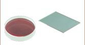
Soft-coated filters are comprised of dielectric layers sandwiched between optical substrates in a housing as shown in Figure 24A. The dielectric layers are often composed of fragile materials such as zinc sulfide, cryolite, or silver. These chemicals react with water, which degrades the performance of the filter, so the shelf life of soft-coated filters is greatly reduced in humid environments. The assembly seals will eventually fail due to the environment, handling, and the construction quality of the filter; the optical performance will rapidly degrade once the seals have failed. Soft-coated filters have a typical lifetime of one to five years in a lab environment owing to these factors.
The laminated structure of the soft-coated filters means that changes in temperature can have a drastic effect on the optical performance of the filter. The dielectric stack, epoxy, optical substrate, absorption glass, and housing may all have different coefficients of thermal expansion. This may result in the shape of the filter changing in unexpected ways with changes in temperature.
Hard-coated filters are produced by sputtering dielectric layers onto a glass substrate; the dielectric filter stack can be exposed to the environment, as shown in Figure 24B, without degradation of performance owing to the material being more environmentally stable than what is used for the soft-coated filters. The hard-coated filters are thinner than soft-coated filters, which allows them to be more easily incorporated into space-limited applications. The sputtering process is automated, highly repeatable, and results in a transmitted wavefront error value that is close to that of the uncoated optic.
The performance of soft-coated filters is limited in the visible wavelengths to approximately 80% transmission if silver is not used and approximately 50% transmission if silver is used in the dielectric stack; the transmission is further limited in the UV. As can be seen in Figure 24C and Figure 24D, the hard-coated filters have improved transmission in the UV and visible wavelength regimes. The cut-on and cut-off for hard-coated filters is relatively steep compared to the soft-coated filters. The transmission is also much flatter for the hard-coated filters compared with the soft-coated, which is due to the sputtering process used that allows more complicated cavity filter designs to be deposited with high precision and repeatability.
 Click to Enlarge
Figure 24D Visible Performance Comparison of Hard- and Soft-Coated Filters
 Click to Enlarge
Figure 24C UV Performance Comparison of Hard- and Soft-Coated Filters
| Posted Comments: | |
Andrey Kuznetsov
(posted 2025-07-06 21:06:06.98) Could you please provide transmission up to at least 2500nm for FELH1000 to FELH2000 products? With filters working in SWIR, it's unclear what the performance limits are if your transmission curves only go up to 2150nm. jdelia
(posted 2025-07-07 04:37:48.0) Thank you for contacting Thorlabs. I have reached out to you directly via email to provide any relevant data on this we may have. Jiajun Yuan
(posted 2025-06-26 15:27:02.81) Rencently, I use this filter to block some light at block band, primary around 1480nm. Since the 1480nm laser power is a little bit high, I would like to know the reflection and transimission data at the block band wavelength range, in order to check the absoption. Do you have any data of this? EGies
(posted 2025-06-26 05:57:33.0) Thank you for contacting Thorlabs. I have contacted you directly regarding the transmission and reflectance data for the FELH1500. Additional data and specifications can be requested by reaching out to us at techsupport@thorlabs.com. Maria D
(posted 2025-04-29 08:29:24.127) Hello, for the shortpass filter FESH1000 I only see listed the damage threshold in J/cm2 for pulsed lasers use. Is it possible to use it for a continuous wave application at 1550nm, and if so, what is the damage threshold in this configuration?
Thanks cdolbashian
(posted 2025-05-01 11:56:56.0) Thank you for reaching out to us with this inquiry. Unfortunately, we do not have official damage threshold data for these filters. Do you think you could share a bit about your intended light source to be used, including the power and beam diameter? Sometimes we are able to confirm compatibility based on our own usage of the part and anecdotal customer experiences. I have contacted you directly to discuss this further. Manoj K
(posted 2025-04-16 07:35:27.823) Dear Thorlabs,
Does FELH0400 has autofluorescence under UV (365 nm) exposure? Thanks EGies
(posted 2025-04-18 05:09:29.0) Thank you for contacting Thorlabs. We have not specifically tested if the FELH0400 exhibits autofluorescence under UV exposure. I have reached out to you directly regarding your particular application. Ulrich Leischner
(posted 2025-03-25 16:07:02.757) Hello
we would need a longpass-filter at 45° for cut-on-wavelength of 1560nm. do you know the transmission data for this filter at 45°? Do you know how other filter ( especially FBH1550-40) behaves at 45°?
Greetings
Uli blarowe
(posted 2025-03-26 09:28:08.0) Thank you for contacting Thorlabs. I've reached out to you directly with data at different AOIs for these filters. For any data not listed on the website, feel free to reach out to techsupport@thorlabs.com Christian Marois
(posted 2024-12-06 15:48:03.287) We are interested in using this filter (FELH0900) as a dichroic to reflect the visible light and transmit the infrared. We are assuming, since this is an interference filter, that everything that is blocked is reflected?
Thx blarowe
(posted 2024-12-09 03:32:56.0) Thank you for contacting Thorlabs. These filters will typically reflect a large portion of the blocked light, though we do not spec these for reflectance, so we cannot guarantee any specific values. We do also have dedicated dichroic filters available, such as the DMLP900. I have reached out to you directly with more details. Ivan S
(posted 2024-10-30 08:13:49.477) Hi, I was wondering about the GDD behaviour of this filter, can I assume its dispersion to be roughly similar to 2 mm of fused silica (substrate thickness) when used in transmission? How much GDD do the dielectric stacks add around 2000 nm wavelength? blarowe
(posted 2024-11-01 02:14:36.0) Thank you for contacting Thorlabs. I've reached out to you directly to discuss this. Additional data and specifications can be requested by reaching out to us at techsupport@thorlabs.com Thinh Tran
(posted 2024-08-09 18:09:23.373) Can we use solvents like acetone or IPA to clean these filters? Thanks cdolbashian
(posted 2024-08-14 11:47:28.0) Thank you for reaching out to us with this inquiry. I would recommend following our guidelines outlined on our cleaning page here: https://www.thorlabs.com/newgrouppage9.cfm?objectgroup_id=9025 N C
(posted 2024-05-21 23:58:21.047) Hi
Do U have a low pass filter for 532 nm
thanks (I like it to reflect 532nm and pass 540nm )
thanks cdolbashian
(posted 2024-05-24 10:38:36.0) Thank you for reaching out to us with this inquiry. You can adjust the center wavelength of filter-optics like this by changing the AOI of your light incident on the surface. I would try the 550nm filter and add a few degrees of tilt to it in order to achieve the pass-band you desire. Andreas Baltzer Skov
(posted 2024-05-03 07:38:17.62) Hi - As already stated in a bunch of the comments, increasing the AOI of the various FELH filters blue-shifts the cut-off wavelength. I am curious as to why this is the case though. The filters are obviously more complex than a simple quarter-wave stack, yet I would assume that as you turn the mirrors, the distance between the dielectric layers increases, thus also increasing the wavelength for which the bragg-condition is satisfied. In other words, I would expect the cut-off wavelength to red-shift.
Could you provide some insight as to why we see a blue-shift instead of a red-shift?
Thanks in advance
- Andreas cdolbashian
(posted 2024-05-24 10:14:04.0) Thank you for reaching out to us with this inquiry. This model can be reduced to interference between light reflecting from the front surface of the optic and from light reflected from the interference layers of the optic. Starting as a normal incidence (0° AOI) and increasing the OPL, we will find that the Optical Path Length (OPL) increases for both rays: the one reflecting in air, and the one reflecting within the dielectric layers. However, the key point here is that while both of them are increasing, the difference between them (OPD) is actually decreasing, with the OPL in Air (from the front surface), increasing at a slightly faster rate than the one through the material. As this is the case, the wavelength shift is a blue shift. Additionally, for filter-like optics which are designed to be used at 45° (such as a dichroic mirror), tilting toward larger angles will blueshift your spectrum, while tilting toward normal incidence will redshift your spectrum. I have contacted you directly with some helpful reference documentation. user
(posted 2024-01-22 10:22:05.787) Could you tell me the approximate thickness of the dielectric coating? Thanks. jpolaris
(posted 2024-01-24 01:15:15.0) Thank you for contacting Thorlabs. Unfortunately, the dielectric coating thickness of these hard-coated edgepass filters is information that we consider to be proprietary. user
(posted 2023-09-14 11:55:16.38) Hey! Do you have any option on higher shortpass filters?
Like 1600nm shortpass or even 1700nmshortpass?
Thank you jpolaris
(posted 2023-09-14 08:09:16.0) Thank you for contacting Thorlabs. At the present moment, we do not have any stock shortpass filters with cutoff wavelengths above 1500 nm. I have reached out to you directly to discuss alternative solutions. Requests for custom optics can be made by emailing us at techsupport@thorlabs.com. Bruce Tiemann
(posted 2023-09-12 11:29:56.69) You already offer downloadable data containing the spectral data for each part. However, it would be super useful to offer a spreadsheet containing the spectral data for all the parts in one giant spreadsheet, such that we don't have to do separate downloads for each individual item.
I am writing this feedback on one of your dielectric edge filters pages, but this comment could equally apply to other filters, including color glass filters, shortpass, longpass, notch and bandpass, as well as substrate transmission spectra, AR coating data, and also mirror and beamsplitter coating spectra.
Maybe a few giant spreadsheets (substrates, color glass, coatings) or something, but, rather than hundreds of different individual optics or coatings.
Thanks! cdolbashian
(posted 2023-09-25 10:46:23.0) Thank you for the suggestion! I have passed this along internally as a potential way in which we can share our test data in a more concise way. If you ever need data which you do not see on the web, please feel free to contact us at Techsupport@thorlabs.com. J. Freitag
(posted 2023-08-03 09:27:00.363) Dear Thorlabs,
If available I would be pleased if you could provide the transmission and reflectance data of the FELH0500 filter at 45 deg AOI to us. Thank you a lot, J. Freitag cdolbashian
(posted 2023-08-10 02:07:38.0) Thank you for reaching out to us with this inquiry. I have contacted you directly with such data. For future inquiries like this, please feel free to reach out to tech support at Techsupport@thorlabs.com. Poul Petersen
(posted 2023-07-04 14:30:46.44) Dear Thorlabs
I am interested in a buying a set of custom sizes of your FELH0600 and FELH0700 filters. The filters should be 46.1 mm in diameter. The thickness is less important. we would be interested in 5-10 filters of each kind (600 and 700 nm shortpass). Would you be able to provide a custom filter size?
thank you
Poul Petersen cdolbashian
(posted 2023-07-21 03:00:51.0) Thank you for reaching out to us with this inquiry. We can very likely fulfill this for you as a custom. I have put you in contact with your local technical sales team. For future requests, please feel free to find the contact information for your closest thorlabs office, and reach out to them directly via email: https://www.thorlabs.com/locations.cfm Michele Cotrufo
(posted 2023-04-08 12:07:33.17) Can you clarify how you calculate the optical density? I am looking at the specs of the FESH1000, inside the file FESH1000_OD.xlsx file.
At a wavelength = 1500nm, the quoted OD is 6.98.
However, in the same file it is mentioned that the transmission at 1500nm is T = 0.00039%. But then OD = - log10(T/100) = 5.4. It differs by more than one order of magnitude. Which values should I trust? cdolbashian
(posted 2023-04-13 11:07:26.0) Thank you for reaching out to us Michele. At the time of posting this, we are looking into the discrepancy and presentation of the raw data you are referring to. As a safe bet, I would simply use the minimum guaranteed performance for these products. In this case, the transmission is guaranteed to be >90% in the pass region, while the OD is guaranteed to be >5 in the blocking region. user
(posted 2023-01-26 10:03:52.77) Hello,
At which incidence angle is the transmission specified?
Thanks! jdelia
(posted 2023-01-26 01:15:57.0) Thank you for contacting Thorlabs. The transmission for these filters is specified at 0 degrees AOI. Martin Nielsen
(posted 2023-01-03 08:05:13.143) Can you provide information on the dependence on angle of incidence for the FELH0900 and the FELH0850 filter? cdolbashian
(posted 2023-01-10 02:31:20.0) Thank you for reaching out to us Martin! We have not tested all of our filters at all AOI, but as a rule of thumb, a 45 deg AOI blue-shifts the cut-on wavelength by roughly 10% compared to 0 deg AOI. Please note though, that this is quite heavily dependent on the input polarization since these are based on dielectric coatings. The desired steepness of transition is also affected. Ruohong Li
(posted 2022-11-09 13:51:03.59) do you have 2 inch diameter option for FELH0400? Thanks jgreschler
(posted 2022-11-17 02:40:55.0) Thank you for reaching out to Thorlabs. Custom items can be requested by reaching out to techsupport@thorlabs.com. This is a configuration we have quoted in the past, I have reached out to you directly to discuss quantity and begin the quoting process. XINJUN LI
(posted 2022-05-26 12:30:04.72) 1.交货期要多久,有现货供应吗 cdolbashian
(posted 2025-03-20 04:33:20.0) Thank you for reaching out to us with this inquiry. For up-to-date shipping and stock information, please contact your local sales team. I have contacted you directly to facilitate this communication. Thinh Tran
(posted 2022-03-30 08:28:23.917) Hi, It would be nicer if there are a selection of short pass filters for IR range from 1000 to 1500 nm with 50 nm step like long pass filters. jdelia
(posted 2022-03-30 11:05:35.0) Thank you for contacting Thorlabs, and for providing this valuable feedback. I will passing this product line request along to our internal suggestion forum. Markus Stabel
(posted 2021-07-27 14:53:25.533) Hello,
I'm looking for a filter that blocks light at 606nm but transmitts it from 610nm (or slightly above) on. Something like an FELH0610 would fit that description. Is this something you can provide?
Or do you have AOI data for the FELH0650 so that I can check if angling that filter far enough moves the cutoff to where I want it?
Thanks. YLohia
(posted 2021-08-03 02:55:45.0) Hello, thank you for contacting Thorlabs. Unfortunately, we don't have AOI data for the FELH0650. As a rule of thumb, a 45 deg AOI blue-shifts the cut-on wavelength by roughly 10% compared to 0 deg AOI, but this is quite heavily dependent on the input polarization since these are based on dielectric coatings. The desired steepness of transition is also affected. Richard Graham
(posted 2021-07-05 14:12:33.827) I was wondering if you have a specification or rough guideline for the maximum CW power for these premium edge-pass filters (FELH and FESH part prefix); I only see specifications for pulsed power.
I understand there would be a difference depending on the spectra due to the difference between reflection and absorption loss mechanisms. I am wondering if all my power is generally within the design range given on the spectra plots, can I assume that the losses will be primarily in reflection, and thus the CW power limit very high? I am wanting to confirm if something on the order of 100 W/cm^2, up to 5W total would be OK.
Thanks. YLohia
(posted 2021-07-12 10:46:41.0) Hello, thank you for contacting Thorlabs. The damage threshold data are listed in the “Damage Threshold” tab for a few of the filters on this page. Unfortunately we do not test every single filter yet but you can use this table for a general guideline on how a filter would perform for different wavelength and pulse length. That being said, given that your power level is 5 W for a 2.5 mm at IR wavelengths (not UV), we would expect your FESH0950 to be fine. Julien Camard
(posted 2021-05-27 11:19:42.53) Hello, I was wondering if these filters have to be used at 90 degrees with respect to the beam direction or if they can be tilted? Thanks! YLohia
(posted 2021-05-27 02:39:10.0) Hello, these filters are designed to be used at 0 degree AOI (normal incidence) and that is the angle the cut-off wavelength is specified for. For any other AOIs, the cut-off wavelength will be blue-shifted. For angle-specific data, please email your local Thorlabs Tech Support team. user
(posted 2021-04-16 18:26:55.303) Hello, in the documentation the Diameter is 25mm with ring and clear aperture diameter is 21.1mm. can you give me the diameter about only the filter without ring? Many thanks YLohia
(posted 2021-04-21 11:51:57.0) Hello, these filters have a 23.3 mm diameter unmounted. user
(posted 2021-04-08 09:29:20.363) Hello, in the documentation the thickness of the filter is quoted as 3.5mm, but that seems to be for the mount. Could you confirm the thickness of just the filter (for optical path length calculations). Many thanks. YLohia
(posted 2021-04-08 11:14:59.0) Hello, thank you for contacting Thorlabs. The thickness of the unmounted optic for these premium hard coated filters is listed on the "Specs" tab as 2 mm. user
(posted 2021-01-14 11:21:38.017) Is it possible to purchase this filter in other sizes? e.g 1.5" or 2.0"? YLohia
(posted 2021-01-14 02:47:13.0) Hello. Custom Edgepass Filter Sizes are available by contacting Tech Support (techsupport@thorlabs.com). We will discuss this directly. user
(posted 2021-01-04 11:59:54.013) Could I know the reflection wavefront distortion on this filter? I'm more caring of reflection quality. Also, could you please provide the angle tolerance data? Consider I may have a incident angle control error up to 5degeree. YLohia
(posted 2021-01-12 02:23:06.0) Thank you for contacting Thorlabs. The FELH0500 filter should have a reflected wavefront error of around 1 wave (estimate), but please note that this can vary between units since this is not a controlled/measured spec. We will reach out to you directly with AOI data. Feng Jin
(posted 2020-10-13 13:10:39.333) How the OD changes versus the incident angle of input light? Do you have a graph for it? YLohia
(posted 2020-10-13 03:22:27.0) Thank you for contacting Thorlabs. I have reached out to you directly with some data. dallas strandell
(posted 2020-09-30 12:51:15.79) Hi,
The specs for the 500nm longpass say the Transmission
Region (T>90%) starts at 508 nm. However the typical data in the excel says the 90% region starts at 500 nm. Which is correct? Thanks YLohia
(posted 2020-10-01 04:02:36.0) Hello, thank you for contacting Thorlabs. The excel file contains typical data, which means that the information on it is taken only from one measurement and can vary between production lots. We formally only guarantee 90% transmission at 508 nm. Please note that the cut-on wavelength can shift to the lower end of the spectrum as a function of AOI. Ke Wang
(posted 2020-01-12 08:47:32.42) Could you pls make High-Performance longpass Filters cutting on between 1600 nm and 1800 nm? YLohia
(posted 2020-01-13 10:12:51.0) Hello, thank you for your suggestion. I have posted your request to our internal engineering forum for consideration of these 1600 nm - 1800 nm longpass filters as future products. TRAIAN MIU
(posted 2019-09-13 15:29:24.063) Is this filter available in a 80 mm diameter as well? nbayconich
(posted 2019-09-16 03:54:44.0) Thank you for contacting Thorlabs. We can provide larger versions of these filters as a custom option. I will reach out to you directly with more information about our custom capabilities. akuznetsov
(posted 2018-10-08 12:25:21.68) Please check with production to make sure the direction arrows are clearly marked (engraved). I received a filter than had a line and a tiny dot at the end of a line, it was not clear that the dot represented an arrow, but I assumed as such. I am used to seeing a full length arrow on your filters. YLohia
(posted 2018-10-25 09:50:05.0) Hello, thank you for your feedback. Please accept our apologies for any inconvenience caused by this. We have finished checking our entire component inventory for these filters, but we did not find any engravings where the arrowhead was a different shape or a dot. That being said, our production team has been made aware of this issue to prevent it from happening again. jurkusk
(posted 2018-09-18 12:12:06.95) Hello,
Could you tell me whether these filters work by absorbing or reflecting the wavelengths that are not transmitted? YLohia
(posted 2018-09-19 02:58:27.0) Hello, most of the rejected band is reflected with minimal absorption. Please note that there will be scatter and, unlike a dichroic mirror, we cannot guarantee the usability of the reflected light. carl.asplund
(posted 2018-09-12 10:41:27.77) Hi,
What is the wavelength dependence on incidence angle for FESH900? We have unpolarized light.
I have the same question for FELH900 if you have that data too.
Best regards,
Carl Asplund nbayconich
(posted 2018-09-14 03:29:48.0) Thank you for contacting Thorlabs. Increasing the AOI will shift the cutoff wavelength of these types of edgepass filters towards a shorter wavelength. Generally the cutoff wavelength will decrease as AOI increases.
We have done more extensive transmission testing for our bandpass and notch pass filters as a function of wavelength. Our webpage located in the link below for our notch filters has an equation that shows how to calculate the passing centerwavelength shift of an interference filter as a function of AOI. A similar effect can be seen for the cutoff wavelength of the edgepass filters.
https://www.thorlabs.com/newgrouppage9.cfm?objectgroup_id=3880#D067E48C-DAAE-4C54-B614-CDDA86B81DF9-3880
I will contact you directly with more information. tug13936
(posted 2018-04-23 18:45:50.27) Can you provide the transmission curve for thsese filters (FELH0700 or FELH0600) with s-polarization and p-polarization? Is there any difference when the polarization is different? nbayconich
(posted 2018-04-27 05:38:57.0) Thank you for your feedback. The Transmission of S & P polarization at an angle of incidence of zero degrees will be the same. At 0 degrees AOI, s and p do not exist and you will see an identical response at 0 degrees AOI to vertical and horizontal polarization. If you are interested in a particular angle of incidence we can provide a scan service for our products. I will contact you directly with more information. mountainskysea
(posted 2017-11-01 17:17:51.043) 问下FL和FB开头的filter有什么区别? tfrisch
(posted 2017-12-13 02:23:48.0) Hello, thank you for contacting Thorlabs. FB nominally stands for Filter-Bandpass, and FL nominally stands for Filter-Laser, though both are bandpass filters. Generally, an FL filter will have a higher peak transmission than an FB with a similar bandwidth. Tao.Jiang
(posted 2017-02-03 16:31:57.723) Dear Thorlabs Team, is it possible to manufacture short pass filter of FESH1100, similar to FESH1000? tfrisch
(posted 2017-02-13 02:12:05.0) Hello, thank you for contacting Thorlabs. It looks like you are already in contact with our Technical Support team on this matter, but I will also post this idea in our internal engineering forum. nejbauer
(posted 2016-10-04 09:25:09.31) Do you know the GVD (group velocity dispersion) for these filters? Or any similar data relevant to femtosecond applications?
Specifically, I interested about GVD for the region 1200-1600 nm in transmission for FELH1100. jlow
(posted 2016-10-10 11:07:36.0) Response from Jeremy at Thorlabs: Unfortunately we do not have GVD data for these filters. daniel.brunner
(posted 2016-02-10 11:13:06.78) Are these filter absorptive or reflective outside of their transmission window? besembeson
(posted 2016-02-11 09:37:17.0) Response from Bweh at Thorlabs USA: Whether it is absorptive or reflective depends on the wavelengths you are looking at. These filters are hard-coated so the blocking band is reflective. Very far away from the design window, some absorption does start to show up. jay.mathews
(posted 2015-09-13 18:54:43.43) It would be nice if you made a longpass filter that would block 1550 nm and let longer wavelengths through. Maybe 1575 or 1600 nm cutoff? 1550 lasers are cheap now, so people are using them as pumping sources for all kinds of spectroscopy and other optical experiments. We need a way to filter out the 1550. besembeson
(posted 2015-09-29 12:11:52.0) Response from Bweh at Thorlabs USA: Thanks for the feedback. We will look into offering this in the future. jorpet
(posted 2015-04-26 09:25:49.19) A long and short pass pair of FELH and FESH at 1050 nm will be very useful for me (and I suppose to many others). It will make a very good blocker/selector for 1064 nm. If one adds FELH 1100 (ore even FELH 1090) it makes a selection of three filters very useful for 1064 nm laser applications. besembeson
(posted 2015-08-28 09:41:30.0) Response from Bweh at Thorlabs USA: We also provide 1064nm bandpass filters with different FWHM values depending on user applications, for example FLH1064-8 or FL1064-10 or the FL1064-3. But in some cases, you can do multiple combinations like you suggested. As these will be so application dependent, it seems easier to make a shortpass-longpass combination as suitable. user
(posted 2014-12-02 10:14:41.57) Do you offer custom wavelength with small amount? or you offer custom wavelength for OEM? cdaly
(posted 2014-12-04 04:22:48.0) Response from Chris at Thorlabs: This may be more feasible at larger OEM quantities, but it would still typically be on a case to case basis. We would be happy to discuss the possibility of smaller quantities as well. Please contact us with your requirements at techsupport@thorlabs.com to discuss this further. aklossek
(posted 2014-07-10 01:46:49.007) Dear ladies and gentlemen,
I would like to know how sensitive are these filters to changes of the incident angle? It is written that the cut-off wavelength shifts of about 10 % between 0° and 45° in case of the standard filters. This would be a shift to 900 nm for the 1000 nm SP. This is enourmous.
Best regards
André Klossek jlow
(posted 2014-07-14 10:41:59.0) Response from Jeremy at Thorlabs: These are dielectric filters and they would be very sensitive to angle of incidence (AOI) change. These are designed for use at 0° AOI. If you require something at 45°, then your application would probably benefit from using other types of filters/mirrors instead. We will contact you directly to discuss about this and come up with a solution. mibr
(posted 2014-02-25 11:51:26.753) Why do Thorlabs not specify the power threshold on your filters? Can they be used with pulsed lasers? jlow
(posted 2014-02-27 03:05:01.0) Response from Jeremy at Thorlabs: The damage threshold data are listed in the “Damage Threshold” tab for a few of the filters on this page. Unfortunately we do not test every single filter yet but you can use this table for a general guideline on how a filter would perform for different wavelength and pulse length. nico.krauss
(posted 2013-11-28 14:19:49.62) I am looking for a premium bandpass filter at 820 nm with a bandwidth of 10 nm. Is it possible to shift the center wavelength of the FBH810-10 to 820nm by rotating? If yes, what kind of losses do I have to expect? Are there any other possible solutions to this problem? tcohen
(posted 2013-12-05 02:59:17.0) Response from Tim at Thorlabs: Thanks for contacting us. Actually, it is possible to change the center wavelength by angle of incidence tuning, but typically as you increase the angle of incidence, the center wavelength goes down. We’ll work on adding some datapoints describing this to our presentation. Although the quality of the premium bandpass filters are higher (transmission, out of band OD, surface quality, etc.), we do offer this as a stock option in our economy line: FB820-10. I’ll contact you to discuss this further. parkse
(posted 2013-09-23 09:13:22.927) Please introduce hard-coated premium shortpass filter for cut-off wavelength of 800 nm which will be used for transimssion of 780 nm (RB) and blocking of 852 nm (Cs) light. cdaly
(posted 2013-09-26 15:09:00.0) Response from Chris at Thorlabs: Thank you for your suggestions. It may be possible to provide a custom filter with this cut-on, but the price would likely increase significantly. Are you able to use a dichroic short pass filter in your application? the DMSP805, when used at 45 degree angle of incidence, has a high transmission at 780, with a high reflectance 852nm, found here: http://www.thorlabs.com/newgrouppage9.cfm?objectgroup_id=3313&pn=DMSP805#5306 lpeterso987
(posted 2013-08-16 12:39:16.687) Your FEL1400 may meet our needs but the FEHL would be better since the transmission is near 100% rather than 80% for the FEL. Is it possible to get the FEHL with a 1400nm cuton?
Also, can you tell me the power handling capabilities of the FEL1400 (or the FEHL). Will it be ok to filter 50 W of laser light? pbui
(posted 2013-08-22 16:09:00.0) Response from Phong at Thorlabs: Thank you for your post. Such a customization would require a custom coating. As for the damage threshold, we do not have a spec for our longpass filters. Our filters may have multiple transmitting and blocking regions. Depending on whether or not the power is concentrated on the transmitted or blocking region, the amount of power will be absorbed by the filter will vary, which will cause the damage threshold to vary as well. We will contact you directly to discuss this within the specifics of your application and to see about the possibility of offering a custom longpass filter. florian.auras
(posted 2013-05-31 12:26:25.94) Dear Thorlabs Team,
these filters have proven to be extremely useful in several of our setups. Would it be possible to extend the portfolio to shorter wavelength regions? A 400 nm or 365 nm filter of this type would be fantastic! Thanks tcohen
(posted 2013-06-06 12:02:00.0) Response from Tim at Thorlabs: Thank you for your suggestion. We are constantly growing our selection and are looking to expand our IBS capabilities to further this line. jlow
(posted 2013-01-21 16:18:00.0) Response from Jeremy at Thorlabs: We can do this for larger diameters. I will get in contact with you directly to discuss about this. roumis.d
(posted 2013-01-21 12:07:06.12) Is there any chance of these lp filters being available in larger diameters.. 50mm would be quite helpful.
Thanks |
| Table G1.1 Specifications | ||||||
|---|---|---|---|---|---|---|
| Item # | Cut-On Wavelength (Transission) | Transmission Region |
Rejection Region (OD>5) |
Transmission Dataa |
Damage Threshold | Diameter |
| FELH0350 | 350 nm (T >85%) | 355 - 2150 nm | 200 - 345 nm | - | Ø25.0 mm | |
| FELH0375 | 375 nm (T >90%) | 381 - 2150 nm | 200 - 369 nm | - | Ø25.0 mm | |
| FELH05400 | 400 nm (T >90%) | 407 - 2150 nm | 200 - 393 nm | - | Ø12.5 mm | |
| FELH0400 | 400 nm (T >90%) | 407 - 2150 nm | 200 - 393 nm | - | Ø25.0 mm | |
| FELH0425 | 425 nm (T >90%) | 431 - 2150 nm | 200 - 419 nm | - | Ø25.0 mm | |
| FELH05450 | 450 nm (T >90%) | 457 - 2150 nm | 200 - 443 nm | - | Ø12.5 mm | |
| FELH0450 | 450 nm (T >90%) | 457 - 2150 nm | 200 - 443 nm | - | Ø25.0 mm | |
| FELH0475 | 475 nm (T >90%) | 482 - 2150 nm | 200 - 468 nm | - | Ø25.0 mm | |
| FELH05500 | 500 nm (T >90%) | 508 - 2150 nm | 200 - 492 nm | - | Ø12.5 mm | |
| FELH0500 | 500 nm (T >90%) | 508 - 2150 nm | 200 - 492 nm | - | Ø25.0 mm | |
| FELH0525 | 525 nm (T >90%) | 533 - 2150 nm | 200 - 517 nm | - | Ø25.0 mm | |
| FELH05550 | 550 nm (T >90%) | 559 - 2150 nm | 200 - 542 nm | 1.0 J/cm2 (532 nm, 10 ns, 10 Hz, Ø0.472 mm) | Ø12.5 mm | |
| FELH0550 | 550 nm (T >90%) | 559 - 2150 nm | 200 - 542 nm | 1.0 J/cm2 (532 nm, 10 ns, 10 Hz, Ø0.472 mm) | Ø25.0 mm | |
| FELH0575 | 575 nm (T >90%) | 583 - 2150 nm | 200 - 566 nm | - | Ø25.0 mm | |
| FELH0600 | 600 nm (T >90%) | 609 - 2150 nm | 200 - 591 nm | - | Ø25.0 mm | |
| FELH0625 | 625 nm (T >90%) | 634 - 2150 nm | 200 - 616 nm | - | Ø25.0 mm | |
| FELH0650 | 650 nm (T >90%) | 660 - 2150 nm | 200 - 641 nm | - | Ø25.0 mm | |
| FELH0675 | 675 nm (T >90%) | 685 - 2150 nm | 200 - 665 nm | - | Ø25.0 mm | |
| FELH05700 | 700 nm (T >90%) | 710 - 2150 nm | 200 - 690 nm | - | Ø12.5 mm | |
| FELH0700 | 700 nm (T >90%) | 710 - 2150 nm | 200 - 690 nm | - | Ø25.0 mm | |
- Click on
 for a plot and downloadable data. Keep in mind that the data given is typical, and performance may vary from lot to lot, particularly outside of the specified region for each filter.
 - The Damage Thresholds tab provides a detailed overview of how laser-induced damage thresholds are measured and how the values may be utilized in determining the appropriateness of an optic for a given application.
| Table G2.1 Specifications | ||||||
|---|---|---|---|---|---|---|
| Item # | Cut-On Wavelength (Transmission) | Transmission Region |
Rejection Region (OD>5) |
Transmission Dataa | Damage Thresholdb | Diameter |
| FELH0725 | 725 nm (T >90%) | 736 - 2150 nm | 200 - 714 nm | - | Ø25.0 mm | |
| FELH05750 | 750 nm (T >90%) | 761 - 2150 nm | 200 - 740 nm | - | Ø12.5 mm | |
| FELH0750 | 750 nm (T >90%) | 761 - 2150 nm | 200 - 740 nm | - | Ø25.0 mm | |
| FELH0775 | 775 nm (T >90%) | 787 - 2150 nm | 200 - 763 nm | - | Ø25.0 mm | |
| FELH05800 | 800 nm (T >90%) | 812 - 2150 nm | 200 - 789 nm | - | Ø12.5 mm | |
| FELH0800 | 800 nm (T >90%) | 812 - 2150 nm | 200 - 789 nm | - | Ø25.0 mm | |
| FELH0825 | 825 nm (T >90%) | 837 - 2150 nm | 200 - 813 nm | - | Ø25.0 mm | |
| FELH05850 | 850 nm (T >90%) | 861 - 2150 nm | 200 - 839 nm | - | Ø12.5 mm | |
| FELH0850 | 850 nm (T >90%) | 861 - 2150 nm | 200 - 839 nm | - | Ø25.0 mm | |
| FELH0875 | 875 nm (T >90%) | 888 - 2150 nm | 200 - 862 nm | - | Ø25.0 mm | |
| FELH05900 | 900 nm (T >90%) | 912 - 2150 nm | 200 - 888 nm | - | Ø12.5 mm | |
| FELH0900 | 900 nm (T >90%) | 912 - 2150 nm | 200 - 888 nm | - | Ø25.0 mm | |
| FELH0925 | 925 nm (T >90%) | 939 - 2150 nm | 200 - 911 nm | - | Ø25.0 mm | |
| FELH05950 | 950 nm (T >90%) | 962 - 2150 nm | 200 - 938 nm | 0.25 J/cm2 (1064 nm, 10 ns, 10 Hz, Ø1.010 mm) | Ø12.5 mm | |
| FELH0950 | 950 nm (T >90%) | 962 - 2150 nm | 200 - 938 nm | 0.25 J/cm2 (1064 nm, 10 ns, 10 Hz, Ø1.010 mm) | Ø25.0 mm | |
| FELH0975 | 975 nm (T >90%) | 990 - 2150 nm | 200 - 960 nm | - | Ø25.0 mm | |
- Click on for a plot and downloadable data. Keep in mind that the data given is typical, and performance may vary from lot to lot, particularly outside of the specified region for each filter.
- The Damage Thresholds tab provides a detailed overview of how laser-induced damage thresholds are measured and how the values may be utilized in determining the appropriateness of an optic for a given application.
| Table G3.1 Specifications | ||||||
|---|---|---|---|---|---|---|
| Item # | Cut-On Wavelength | Transmission Region |
Rejection Region (OD>5) |
Transmission Dataa | Damage Thresholdb | Diameter |
| FELH051000 | 1000 nm (T >90%) | 1013 - 2150 nm | 200 - 987 nm | 3.75 J/cm2 (1064 nm, 10 ns, 10 Hz, Ø0.516 mm) | Ø12.5 mm | |
| FELH1000 | 1000 nm (T >90%) | 1013 - 2150 nm | 200 - 987 nm | 3.75 J/cm2 (1064 nm, 10 ns, 10 Hz, Ø0.516 mm) | Ø25.0 mm | |
| FELH051050 | 1050 mm (T >90%) | 1063 - 2150 nm | 200 - 1037 nm | 0.1 J/cm2 (532 nm, 10 ns, 10 Hz, Ø0.360 mm) | Ø12.5 mm | |
| FELH1050 | 1050 nm (T >90%) | 1063 - 2150 nm | 200 - 1037 nm | 0.1 J/cm2 (532 nm, 10 ns, 10 Hz, Ø0.360 mm) | Ø25.0 mm | |
| FELH051100 | 1100 nm (T >90%) | 1114 - 2150 nm | 200 - 1086 nm | - | Ø12.5 mm | |
| FELH1100 | 1100 nm (T >90%) | 1114 - 2150 nm | 200 - 1086 nm | - | Ø25.0 mm | |
| FELH051150 | 1150 nm (T >90%) | 1164 - 2150 nm | 200 - 1136 nm | - | Ø12.5 mm | |
| FELH1150 | 1150 nm (T >90%) | 1164 - 2150 nm | 200 - 1136 nm | - | Ø25.0 mm | |
| FELH051200 | 1200 nm (T >90%) | 1215 - 2150 nm | 200 - 1185 nm | - | Ø12.5 mm | |
| FELH1200 | 1200 nm (T >90%) | 1215 - 2150 nm | 200 - 1185 nm | - | Ø25.0 mm | |
| FELH051250 | 1250 nm (T >90%) | 1265 - 2150 nm | 200 - 1235 nm | - | Ø12.5 mm | |
| FELH1250 | 1250 nm (T >90%) | 1265 - 2150 nm | 200 - 1235 nm | - | Ø25.0 mm | |
| FELH051300 | 1300 nm (T >90%) | 1316 - 2150 nm | 200 - 1284 nm | - | Ø12.5 mm | |
| FELH1300 | 1300 nm (T >90%) | 1316 - 2150 nm | 200 - 1284 nm | - | Ø25.0 mm | |
- Click on for a plot and downloadable data. Keep in mind that the data given is typical, and performance may vary from lot to lot, particularly outside of the specified region for each filter.
- The Damage Thresholds tab provides a detailed overview of how laser-induced damage thresholds are measured and how the values may be utilized in determining the appropriateness of an optic for a given application.
| Table G4.1 Specifications | ||||||
|---|---|---|---|---|---|---|
| Item # | Cut-On Wavelength | Transmission Region |
Rejection Region (OD>5) |
Transmission Dataa | Damage Thresholdb | Diameter |
| FELH051350 | 1350 nm (T >90%) | 1366 - 2150 nm | 200 - 1334 nm | - | Ø12.5 mm | |
| FELH1350 | 1350 nm (T >90%) | 1366 - 2150 nm | 200 - 1334 nm | - | Ø25.0 mm | |
| FELH051400 | 1400 nm (T >90%) | 1417 - 2150 nm | 200 - 1383 nm | - | Ø12.5 mm | |
| FELH1400 | 1400 nm (T >90%) | 1417 - 2150 nm | 200 - 1383 nm | - | Ø25.0 mm | |
| FELH051450 | 1450 nm (T >90%) | 1467 - 2150 nm | 200 - 1433 nm | - | Ø12.5 mm | |
| FELH1450 | 1450 nm (T >90%) | 1467 - 2150 nm | 200 - 1433 nm | - | Ø25.0 mm | |
| FELH051500 | 1500 nm (T >90%) | 1518 - 2150 nm | 200 - 1482 nm | - | Ø12.5 mm | |
| FELH1500 | 1500 nm (T >90%) | 1518 - 2150 nm | 200 - 1482 nm | - | Ø25.0 mm | |
| FELH1550 | 1550 nm (T >90%) | 1573 - 2150 nm | 200 - 1527 nm | - | ||
| FELH1600 | 1600 nm (T >90%) | 1624 - 2150 nm | 200 - 1576 nm | - | ||
| FELH1650 | 1650 nm (T >90%) | 1675 - 2150 nm | 200 - 1625 nm | - | ||
| FELH1700 | 1700 nm (T >90%) | 1726 - 2150 nm | 200 - 1675 nm | - | ||
| FELH1800 | 1800 nm (T >90%) | 1827 - 2150 nm | 200 - 1773 nm | - | ||
| FELH1900 | 1900 nm (T >90%) | 1929 - 2150 nm | 200 - 1872 nm | - | ||
| FELH2000 | 2000 nm (T >90%) | 2030 - 2150 nm | 200 - 1970 nm | - | ||
- Click on for a plot and downloadable data. Keep in mind that the data given is typical, and performance may vary from lot to lot, particularly outside of the specified region for each filter.
- The Damage Thresholds tab provides a detailed overview of how laser-induced damage thresholds are measured and how the values may be utilized in determining the appropriateness of an optic for a given application.
| Table G6.1 Specifications | ||||||
|---|---|---|---|---|---|---|
| Item # | Cut-Off Wavelength | Transmission Region |
Rejection Region (OD>5) |
Transmission Dataa | Damage Thresholdb | Diameter |
| FESH05450 | 450 nm (T >90%) | 400 - 444 nm | 456 - 1200 nm | - | Ø12.5 mm | |
| FESH0450 | 450 nm (T >90%) | 400 - 444 nm | 456 - 1200 nm | - | Ø25.0 mm | |
| FESH05500 | 500 nm (T >90%) | 400 - 494 nm | 506 - 1200 nm | - | Ø12.5 mm | |
| FESH0500 | 500 nm (T >90%) | 400 - 494 nm | 506 - 1200 nm | - | Ø25.0 mm | |
| FESH05550 | 550 nm (T >90%) | 400 - 543 nm | 557 - 1200 nm | - | Ø12.5 mm | |
| FESH0550 | 550 nm (T >90%) | 400 - 543 nm | 557 - 1200 nm | - | Ø25.0 mm | |
| FESH05600 | 600 nm (T >90%) | 400 - 592 nm | 608 - 1200 nm | 3 J/cm2 (1064 nm, 10 ns, 10 Hz, Ø0.429 mm) |
Ø12.5 mm | |
| FESH0600 | 600 nm (T >90%) | 400 - 592 nm | 608 - 1200 nm | 3 J/cm2 (1064 nm, 10 ns, 10 Hz, Ø0.429 mm) |
Ø25.0 mm | |
| FESH05650 | 650 nm (T >90%) | 400 - 640 nm | 660 - 1200 nm | - | Ø12.5 mm | |
| FESH0650 | 650 nm (T >90%) | 400 - 640 nm | 660 - 1200 nm | - | Ø25.0 mm | |
| FESH05700 | 700 nm (T >90%) | 400 - 690 nm | 711 - 1200 nm | 1.0 J/cm2 (532 nm, 10 ns, 10 Hz, Ø0.472 mm) |
Ø12.5 mm | |
| FESH0700 | 700 nm (T >90%) | 400 - 690 nm | 711 - 1200 nm | 1.0 J/cm2 (532 nm, 10 ns, 10 Hz, Ø0.472 mm) |
Ø25.0 mm | |
- Click on for a plot and downloadable data. Keep in mind that the data given is typical, and performance may vary from lot to lot, particularly outside of the specified region for each filter.
- The Damage Thresholds tab provides a detailed overview of how laser-induced damage thresholds are measured and how the values may be utilized in determining the appropriateness of an optic for a given application.
| Table G7.1 Specifications | ||||||
|---|---|---|---|---|---|---|
| Item # | Cut-Off Wavelength | Transmission Region |
Rejection Region (OD>5) |
Transmission Dataa | Damage Thresholdb | Diameter |
| FESH05750 | 750 nm (T >90%) | 400 - 740 nm | 761 - 1200 nm | - | Ø12.5 mm | |
| FESH0750 | 750 nm (T >90%) | 400 - 740 nm | 761 - 1200 nm | - | Ø25.0 mm | |
| FESH05800 | 800 nm (T >90%) | 500 - 789 nm | 811 - 1500 nm | - | Ø12.5 mm | |
| FESH0800 | 800 nm (T >90%) | 500 - 789 nm | 811 - 1500 nm | - | Ø25.0 mm | |
| FESH05850 | 850 nm (T >90%) | 500 - 839 nm | 861 - 1500 nm | - | Ø12.5 mm | |
| FESH0850 | 850 nm (T >90%) | 500 - 839 nm | 861 - 1500 nm | - | Ø25.0 mm | |
| FESH05900 | 900 nm (T >90%) | 550 - 880 nmc | 920 - 1500 nm | - | Ø12.5 mm | |
| FESH0900 | 900 nm (T >90%) | 550 - 880 nmc | 920 - 1500 nm | - | Ø25.0 mm | |
| FESH0950 | 950 nm (T >90%) | 575 - 930 nmd | 970 - 1500 nm | - | Ø25.0 mm | |
| FESH051000 | 1000 nm (T >90%) | 500 - 987 nm | 1013 - 1500 nm | 7.5 J/cm2 (1064 nm, 10 ns, 10 Hz, Ø0.516 mm) |
Ø12.5 mm | |
| FESH1000 | 1000 nm (T >90%) | 500 - 987 nm | 1013 - 1500 nm | 7.5 J/cm2 (1064 nm, 10 ns, 10 Hz, Ø0.516 mm) |
Ø25.0 mm | |
- Click on for a plot and downloadable data. Keep in mind that the data given is typical, and performance may vary from lot to lot, particularly outside of the specified region for each filter.
- The Damage Thresholds tab provides a detailed overview of how laser-induced damage thresholds are measured and how the values may be utilized in determining the appropriateness of an optic for a given application.
- The average transmission of FESH05900 and FESH0900 from 500 - 550 nm is >90%.
- The average transmission of FESH0950 from 500 - 575 nm is >90%.
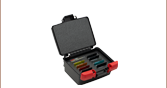
These Hard-Coated Longpass Filter Kits contain ten of our Ø25.0 mm mounted longpass filters. The filter housings are labeled with the part number and an arrow denoting the transmission direction. The filters come in a storage case to help keep the optics organized and protected from physical damage. Table G3.1 contains a list of filters included in each of the kits.
| Table G8.1 Specifications | ||||||||||
|---|---|---|---|---|---|---|---|---|---|---|
| Kit Item # |
Included Filter Item # |
Cut-On Wavelength (Transmission) |
Transmission Region |
Rejection Region (OD>5) |
Transmission/ OD Dataa |
Included Filter Item # |
Cut-On Wavelength (Transmission) |
Transmission Region |
Rejection Region (OD>5) |
Transmission/ OD Dataa |
| FKLPVIS | FELH0500 | 500 nm (T >90%) | 508 - 2150 nm | 200 - 492 nm | FELH0750 | 750 nm (T >90%) | 761 - 2150 nm | 200 - 740 nm | ||
| FELH0550 | 550 nm (T >90%) | 559 - 2150 nm | 200 - 542 nm | FELH0800 | 800 nm (T >90%) | 812 - 2150 nm | 812 - 2150 nm |
|||
| FELH0600 | 600 nm (T >90%) | 609 - 2150 nm | 200 - 591 nm | FELH0850 | 850 nm (T >90%) | 861 - 2150 nm | 200 - 839 nm | |||
| FELH0650 | 650 nm (T >90%) | 660 - 2150 nm | 200 - 641 nm | FELH0900 | 900 nm (T >90%) | 912 - 2150 nm | 200 - 888 nm | |||
| FELH0700 | 700 nm (T >90%) | 710 - 2150 nm | 200 - 690 nm | FELH0950 | 950 nm (T >90%) | 962 - 2150 nm | 200 - 938 nm |
|||
| FKLPIR | FELH1000 | 1000 nm (T >90%) | 1013 - 2150 nm | 200 - 987 nm | FELH1250 | 1250 nm (T >90%) | 1265 - 2150 nm | 200 - 1235 nm |
||
| FELH1050 | 1050 nm (T >90%) | 1063 - 2150 nm | 200 - 1037 nm | FELH1300 | 1300 nm (T >90%) | 1316 - 2150 nm | 200 - 1284 nm |
|||
| FELH1100 | 1100 nm (T >90%) | 1114 - 2150 nm | 200 - 1086 nm |
FELH1350 | 1350 nm (T >90%) | 1366 - 2150 nm | 200 - 1334 nm |
|||
| FELH1150 | 1150 nm (T >90%) | 1164 - 2150 nm | 200 - 1136 nm |
FELH1400 | 1400 nm (T >90%) | 1417 - 2150 nm | 200 - 1383 nm |
|||
| FELH1200 | 1200 nm (T >90%) | 1215 - 2150 nm | 200 - 1185 nm |
FELH1500 | 1500 nm (T >90%) | 1518 - 2150 nm | 200 - 1482 nm |
|||
- Click on for a plot and downloadable data. The shaded regions in these graphs denote the spectral ranges over which we recommend using these filters. Please keep in mind that the data given is typical, and performance may vary from lot to lot, particularly outside of the shaded regions.
This Hard-Coated Shortpass Filter Kit contains ten of our Ø25.0 mm mounted shortpass filters. The filter housings are labeled with the part number and an arrow denoting the transmission direction. The filters come in a storage case to help keep the optics organized and protected from physical damage. Table G4.1 contains a list of the filters included.
| Table G9.1 Specifications | ||||||||||
|---|---|---|---|---|---|---|---|---|---|---|
| Kit Item # |
Filter Included | Cut-Off Wavelength (Transmission) |
Transmission Region |
Rejection Region (OD>5) |
Transmission/ OD Dataa |
Filter Included | Cut-Off Wavelength (Transmission) |
Transmission Region |
Rejection Region (OD>5) |
Transmission/ OD Dataa |
| FKSPVIS | FESH0450 | 450 nm (T >90%) | 400 - 444 nm | 456 - 1200 nm | FESH0700 | 700 nm (T >90%) | 400 - 690 nm | 711 - 1200 nm | ||
| FESH0500 | 500 nm (T >90%) | 400 - 494 nm | 506 - 1200 nm | FESH0750 | 750 nm (T >90%) | 400 - 740 nm | 761 - 1200 nm | |||
| FESH0550 | 550 nm (T >90%) | 400 - 543 nm | 557 - 1200 nm | FESH0800 | 800 nm (T >90%) | 500 - 789 nm | 811 - 1500 nm | |||
| FESH0600 | 600 nm (T >90%) | 400 - 592 nm | 608 - 1200 nm | FESH0900 | 900 nm (T >90%) | 550 - 880 nmb | 920 - 1500 nm | |||
| FESH0650 | 650 nm (T >90%) | 400 - 640 nm | 660 - 1200 nm | FESH1000 | 1000 nm (T >90%) | 500 - 987 nm | 1013 - 1500 nm | |||
- Click on for a plot and downloadable data. The shaded regions in these graphs denote the spectral ranges over which we recommend using these filters. Please keep in mind that the data given is typical, and performance may vary from lot to lot, particularly outside of the shaded regions.
- The average transmission of FESH0900 from 500 - 550 nm is >90%.