 Products Home / Fiber Components / Collimation / Coupling / Triplet Fiber Optic Collimators/Couplers
 Triplet Fiber Optic Collimators/Couplers
- Triplet Lens Design Provides Nearly Gaussian Output
- Low Wavefront Error: λ/8 (Peak-to-Valley, Typical)
- FC/PC and FC/APC Receptacles Available
- Available with Focal Lengths Near 6 mm, 12 mm, 18 mm, or 25 mm
TC25FC-1064
TC18APC-780
TC06APC-405
TC12FC-1550
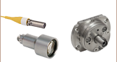
Front
Back
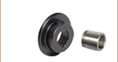
Our Triplet Collimators Use
an Air-Spaced Design


Please Wait
Click for Details
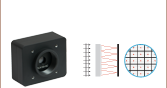
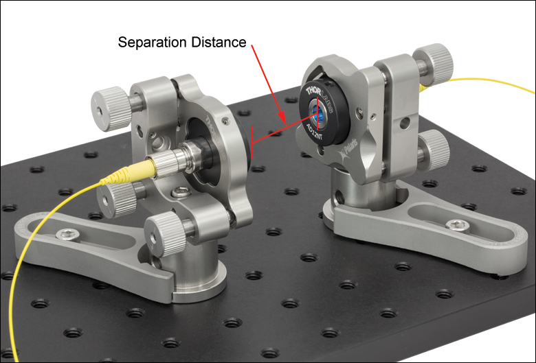
Figure 1.1 Triplet Fiber Collimation Packages can be used for collimator-to-collimator coupling with separation distances from 50 mm to 2 m. The separation distance is the distance between the front lens' surfaces.
Features
- Prealigned for 405 nm, 532 nm, 543 nm, 633 nm, 780 nm, 850 nm, 980 nm, 1060 nm, 1310 nm, 1550 nm, or 2 µm
- Available with 6 mm, 12 mm, 18 mm, or 25 mm Effective Focal Length
- Can be Used as a Coupler or Collimator
- Full-Angle Divergence: ≤0.119° (See Tables G1.1 through G8.1)
- Available with Either an FC/PC or FC/APC 2.2 mm Wide Key Connector
- Low Pointing Error
- FC/PC: 2 mrad (Max)
- FC/APC: 3 mrad (Max)
- Each Collimator Includes a Test Data Sheet
- Non-Magnetic Stainless Steel Housing
Thorlabs' Triplet Fiber Collimators use air-spaced triplet lenses that produce beam quality superior to aspheric lens collimators. The benefits of the low-aberration triplet design include an M2 term closer to 1 (Gaussian), less divergence, and less wavefront error. Detailed performance testing results comparing these triplet collimators to our fixed aspheric collimators are presented on the Performance tab.
Our triplet fiber collimators are available from stock with alignment wavelengths ranging from 405 nm to 2 μm, effective focal lengths (EFL) of approximately 6 mm, 12 mm, 18 mm, or 25 mm, and either an FC/PC or FC/APC connector. The exact focal length at the specified wavelength for each collimator is given in Tables G1.1 through G8.1. Each lens in the collimator has a broadband antireflection coating (see the Coatings tab) in order to minimize losses caused by surface reflections.
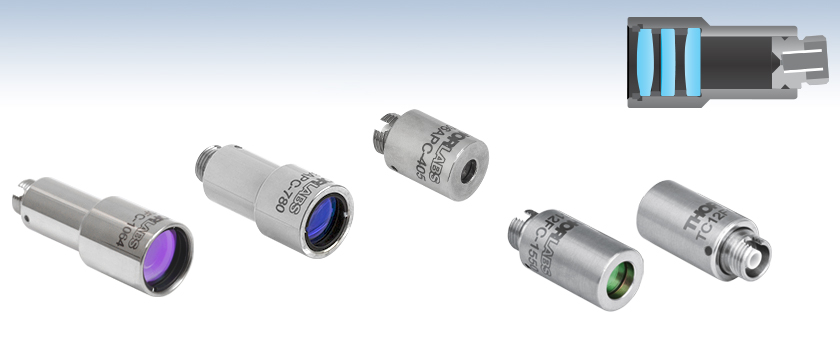
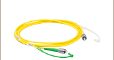
In order to take full advantage of the superior beam quality, we recommend using our triplet collimators with our AR-coated single mode or polarization-maintaining fiber optic patch cables. These cables, which are available with either an FC/PC or FC/APC 2.0 mm narrow key connector, have an antireflective coating on one fiber end for increased transmission and improved return loss at the fiber-to-free-space interface.
 Zemax Files Zemax Files |
|---|
| Click on the red Document icon next to the item numbers below to access the Zemax file download. Our entire Zemax Catalog is also available. |
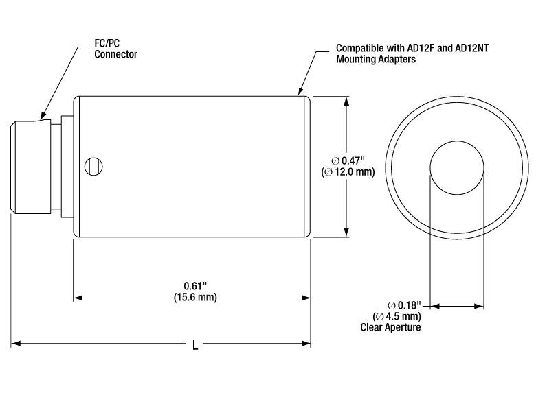
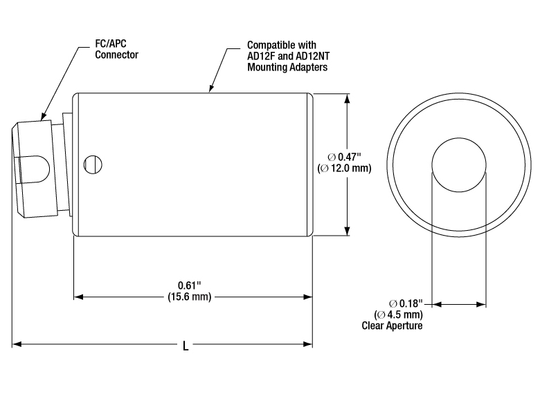
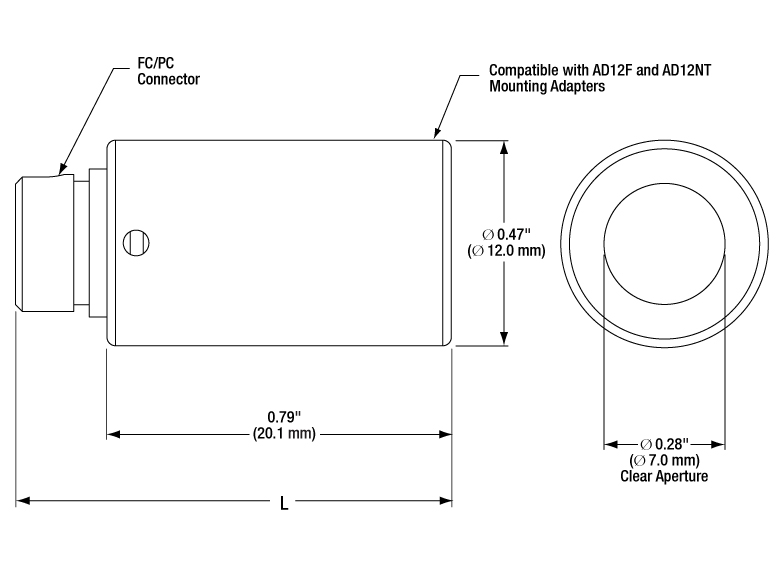
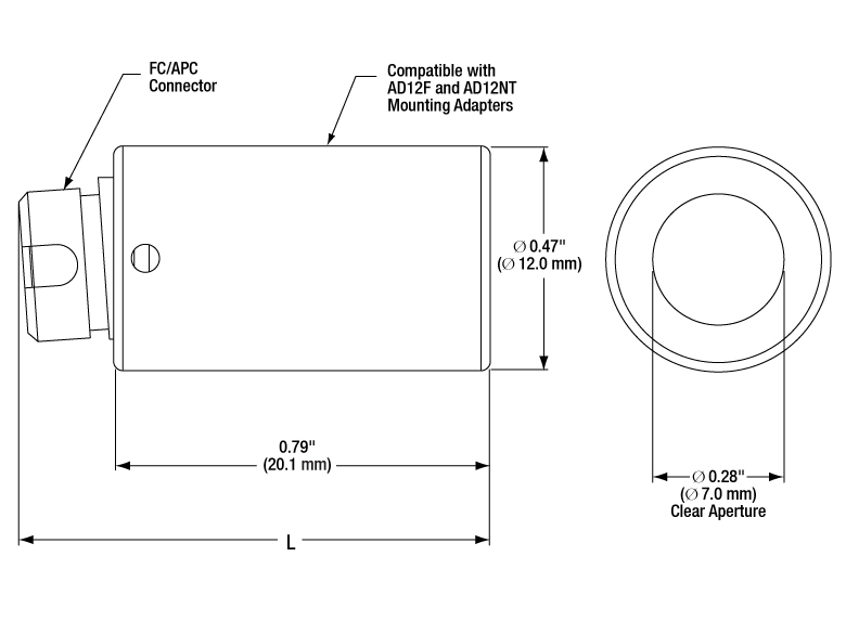
These triplet collimator packages use high-precision 2.2 mm wide key connectors with tightly toleranced ceramic sleeves that provide excellent pointing repeatability, allowing the user to easily remove and replace the fiber. Please note that careful alignment is needed when mating a narrow key PM fiber with the collimator's wide key receptacle. The receptacles for the APC versions are angled so that light exiting the fiber enters the collimator perpendicular to the focal plane. All of our triplet collimators are compatible with the AD12BA, AD12F, AD12NT, KAD12F, or KAD12NT collimator mounting adapters. The longer collimators have a housing design that makes them compatible with additional adapters; triplet collimators with an EFL of approximately 18 mm are also compatible with the AD15F, AD15NT, and AD15F2 adapters, while those with an EFL of approximately 25 mm are also compatible with the AD16F and AD16NT adapters. The collimation packages with external M12 x 0.5 threading are compatible without an adapter with our cage plate CP1M12(/M) to be integrated into our 30 mm cage system.
For triplet collimators aligned to a wavelength other than what is available from stock, please contact Tech Support for additional information. Performance of each collimator over an extended wavelength range can be obtained by the using the black box Zemax files. Please see the Zemax Files tab for more information on these files.
When using these collimators as a free-space coupler, precise alignment is needed for good coupling efficiency. We recommend using a kinematic tip and tilt mount paired with an XYZ adjustable platform (such as our KM100V and MT3 (MT3/M), or our 6-axis kinematic mount paired with a lens tube coupler (K6XS with AD12F or AD16F). Additional collimator mounting adapters are also available, including Ø1/2" and Ø1" unthreaded versions and externally threaded SM05 (0.535"-40), RMS (0.800"-36), or SM1 (1.035"-40) versions. Additionally, these couplers may be used in pairs with a free-space beam between the lenses. This free-space beam can be manipulated with many types of optics prior to entering the second lens. See the Performance Tab for back-coupling efficiency graphs for these collimators.
We also offer a line of aspheric fiber collimators, including our fixed collimators and our FiberPort adjustable collimation packages, that are well suited for use with a wide range of wavelengths. For our complete line of collimation and coupling options, please see the Collimator Guide tab.
Triplet Collimator Performance
Click for Details of Shaded Region
Figure 2.2 The graph above compares the pointing repeatability of an aspheric lens collimator to that of a TC12 triplet collimator. Beam deviation is graphed in X and Y components, each measured in microradians. Nineteen data points were taken with each collimator type, and the beam's position was measured on a beam profiler. This graph shows beam deviation when a fiber is inserted into and removed from the receptacle many times, and is not necessarily a measure of the beam pointing error between the centerline of mechanical reference and the optical axis.
Our triplet collimators use 2.2 mm wide key fiber connectors with tightly toleranced ceramic sleeves, leading to a pointing accuracy that is an order of magnitude better than that of a similar aspheric lens collimator without a high-precision fiber receptacle. Features such as this make our triplet collimators excellent choices for demanding applications.
Figure 2.1 The graph above plots the beam quality, M2, of 68 TC12 triplet collimators and 68 aspheric collimators. The measured beam qualities have been binned into increments of 0.02. For example, the two bars between 1.00 and 1.02 represent the number of units tested that had M2 values between 1.00 and 1.019.
This data shows that beam quality when using a triplet collimator is typically closer to 1, making it more Gaussian than when using an aspheric collimator. It also shows that beam quality achieved with a triplet collimator is more consistent from unit to unit.
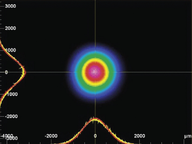
Figure 2.3 Beam Profile: This nearly Gaussian beam profile measured with our former generation BC106-VIS camera beam profiler is of the beam created by collimating the output of an SM fiber-coupled HeNe laser using a TC12FC-633 Triplet Collimation Package. The Gaussian fit is shown by the red line overlaying the data.

Figure 2.4 Wavefront Error: The graph above represents the wavefront error of a collimated beam using a TC12 triplet collimator. Each contour line represents 0.02 waves of wavefront error. Another measure of a beam's quality is the flatness of the wavefront at an image plane conjugate to the fiber tip. Using our previous generation WFS150-5C CCD wavefront sensor, we measured the wavefront of a 633 nm beam collimated with a triplet collimator. The result was less than λ/8 deviation from a flat wavefront.

Click for Details
Figure 2.5 Triplet fiber collimation packages can be used for collimator-to-collimator coupling as shown in the above setup. The separation distance is the distance between the front lens' surfaces.
Back-Coupling Efficiency
Light exiting one triplet collimator can be fed back into a fiber through another triplet collimator, as seen in Figure 2.5. The coupling efficiencies for a subset of pairs of triplet collimators sold on this page are plotted below as a function of the separation distance, which is the distance between the front lens surfaces. This data was experimentally measured using the two-collimator setup shown in Figure 2.5 or by using a mirror (not shown below) to reflect the light back into the same collimator. Back-coupling efficiency is the same for FC/PC- and FC/APC-connectorized collimators.
| θ | Divergence Angle |
| D | Mode-Field Diameter (MFD) |
| f | Focal Length of Collimator |
The divergence angle (in Degrees)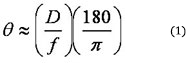 ,
,
where D and f must be in the same units.
Theoretical Approximation of the Divergence Angle
The divergence angle listed in Tables G1.1 through G8.1 is the theoretical full-angle divergence when using the fiber collimator at its design wavelength with the listed fiber. This divergence angle is calculated using Equation 1, given that the light emerging from the fiber has a Gaussian intensity profile. This equation works well for single mode fibers but will underestimate the divergence angle for multimode fibers where the light emerging from the fiber has a non-Gaussian intensity profile. The graphs below illustrate the theoretical beam diameter as a function of propagation distance for each of our collimators.

Figures 4.1 through 4.4 show the reflectance with respect to wavelength of the AR coatings used on the 6 lens surfaces in our triplet fiber optic collimators/couplers. The blue shaded region indicates the wavelength range specified for each coating. Table 4.5 details which AR coating is used with each item.
Click to Enlarge
Figure 4.1 This applies to item numbers with the suffixes -405, -532, -543, and -633.
Click to Enlarge
Figure 4.2 This applies to item numbers with the suffixes -780, -850, and -980.
Click to Enlarge
Figure 4.3 This applies to item numbers with the suffixes -1064, -1310, and -1550.
| Table 4.5 Antireflection Coatings | |||
|---|---|---|---|
| Item # Suffix | Coating | Wavelength Range | Reflectance |
| -405 -532 -543 -633 |
A | 400 - 650 nma | |
| -780 -850 -980 |
B | 650 - 1050 nm | Rmax < 0.5% |
| -1064 -1310 -1550 |
C | 1050 - 1650 nm | Rmax < 0.5% |
| -2000 | 1650 - 2400 nm | 1650 - 2400 nm | Rmax < 1% |
| 1970 - 2030 nm | Rmax < 0.5% | ||
| Zemax Files |
|---|
| Click on the red Document icon next to the item numbers below to access the Zemax file download. |
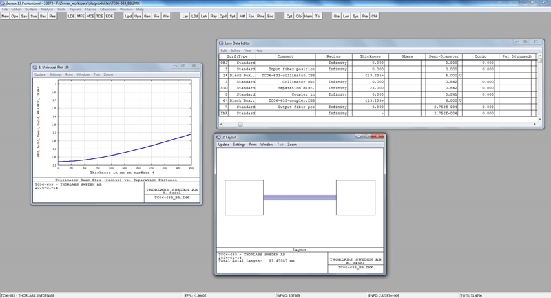
Performance over an extended wavelength range can be obtained by using the black box Zemax files. Figures 5.1 through 5.3 are screen shots of what you will see when you open the file as well as descriptions on how to change the operating wavelength. For this example, the TC06FC-633 black box file was used. Using these black box files allows you to see how the beam profile will change as you move away from the alignment wavelength.
Click to Enlarge
Figure 5.1 The black box Zemax file should display this screen upon opening the file.
Click to Enlarge
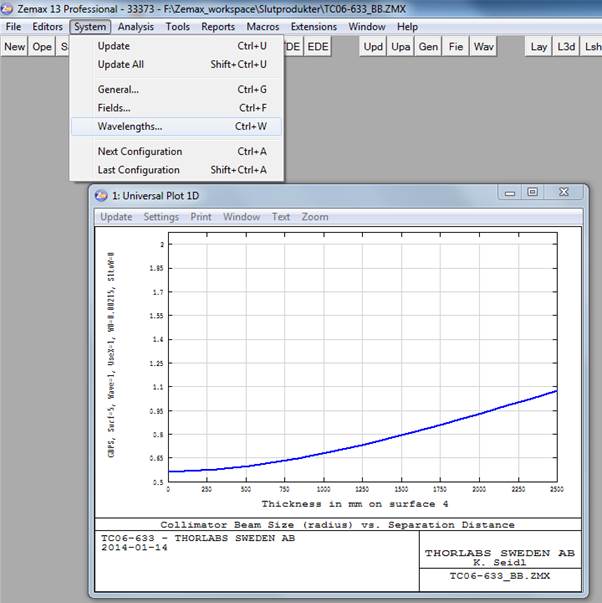
Figure 5.2 Click on "System" in the program header bar and then select "Wavelengths".
Click to Enlarge
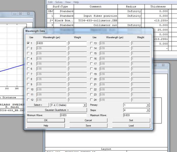
Figure 5.3 Change the current alignment wavelength, indicated by the first checkmarked row, to your operating wavelength. Click "Update" in the graph window from the previous screen.
| Table 6.1 Damage Threshold Specifications | |
|---|---|
| Item # Suffix | Damage Threshold |
| -405 -532 -543 -633 |
3 J/cm2 (532 nm, 10 Hz, 10 ns, Ø408 µm) |
| -780 -850 -980 |
7.5 J/cm2 (810 nm, 10 Hz, 10 ns, Ø76.9 µm) |
| -1064 -1310 -1550 |
3 J/cm2 (1542 nm, 1 Hz, 10 ns, Ø268 µm) |
| -2000 | 2 J/cm2 (2.05 µm, 10 Hz, 10 ns, Ø186 µm) |
Damage Threshold Data for Triplet Collimator/Coupler AR Coatings
The specifications in Table 6.1 are measured data for the antireflective (AR) coatings deposited onto the optical surface of our triplet fiber optic collimators and couplers. Damage threshold specifications are constant for a given coating type, regardless of the focal length and connector type.
Laser Induced Damage Threshold Tutorial
The following is a general overview of how laser induced damage thresholds are measured and how the values may be utilized in determining the appropriateness of an optic for a given application. When choosing optics, it is important to understand the Laser Induced Damage Threshold (LIDT) of the optics being used. The LIDT for an optic greatly depends on the type of laser you are using. Continuous wave (CW) lasers typically cause damage from thermal effects (absorption either in the coating or in the substrate). Pulsed lasers, on the other hand, often strip electrons from the lattice structure of an optic before causing thermal damage. Note that the guideline presented here assumes room temperature operation and optics in new condition (i.e., within scratch-dig spec, surface free of contamination, etc.). Because dust or other particles on the surface of an optic can cause damage at lower thresholds, we recommend keeping surfaces clean and free of debris. For more information on cleaning optics, please see our Optics Cleaning tutorial.
Testing Method
Thorlabs' LIDT testing is done in compliance with ISO/DIS 11254 and ISO 21254 specifications.
First, a low-power/energy beam is directed to the optic under test. The optic is exposed in 10 locations to this laser beam for 30 seconds (CW) or for a number of pulses (pulse repetition frequency specified). After exposure, the optic is examined by a microscope (~100X magnification) for any visible damage. The number of locations that are damaged at a particular power/energy level is recorded. Next, the power/energy is either increased or decreased and the optic is exposed at 10 new locations. This process is repeated until damage is observed. The damage threshold is then assigned to be the highest power/energy that the optic can withstand without causing damage. A histogram such as that shown in Figure 37B represents the testing of one BB1-E02 mirror.
Figure 37A This photograph shows a protected aluminum-coated mirror after LIDT testing. In this particular test, it handled 0.43 J/cm2 (1064 nm, 10 ns pulse, 10 Hz, Ø1.000 mm) before damage.
Figure 37B Example Exposure Histogram used to Determine the LIDT of
| Table 37C Example Test Data | |||
|---|---|---|---|
| Fluence | # of Tested Locations | Locations with Damage | Locations Without Damage |
| 1.50 J/cm2 | 10 | 0 | 10 |
| 1.75 J/cm2 | 10 | 0 | 10 |
| 2.00 J/cm2 | 10 | 0 | 10 |
| 2.25 J/cm2 | 10 | 1 | 9 |
| 3.00 J/cm2 | 10 | 1 | 9 |
| 5.00 J/cm2 | 10 | 9 | 1 |
According to the test, the damage threshold of the mirror was 2.00 J/cm2 (532 nm, 10 ns pulse, 10 Hz, Ø0.803 mm). Please keep in mind that these tests are performed on clean optics, as dirt and contamination can significantly lower the damage threshold of a component. While the test results are only representative of one coating run, Thorlabs specifies damage threshold values that account for coating variances.
Continuous Wave and Long-Pulse Lasers
When an optic is damaged by a continuous wave (CW) laser, it is usually due to the melting of the surface as a result of absorbing the laser's energy or damage to the optical coating (antireflection) [1]. Pulsed lasers with pulse lengths longer than 1 µs can be treated as CW lasers for LIDT discussions.
When pulse lengths are between 1 ns and 1 µs, laser-induced damage can occur either because of absorption or a dielectric breakdown (therefore, a user must check both CW and pulsed LIDT). Absorption is either due to an intrinsic property of the optic or due to surface irregularities; thus LIDT values are only valid for optics meeting or exceeding the surface quality specifications given by a manufacturer. While many optics can handle high power CW lasers, cemented (e.g., achromatic doublets) or highly absorptive (e.g., ND filters) optics tend to have lower CW damage thresholds. These lower thresholds are due to absorption or scattering in the cement or metal coating.
Figure 37D LIDT in linear power density vs. pulse length and spot size. For long pulses to CW, linear power density becomes a constant with spot size. This graph was obtained from [1].
Figure 37E Intensity Distribution of Uniform and Gaussian Beam Profiles
Pulsed lasers with high pulse repetition frequencies (PRF) may behave similarly to CW beams. Unfortunately, this is highly dependent on factors such as absorption and thermal diffusivity, so there is no reliable method for determining when a high PRF laser will damage an optic due to thermal effects. For beams with a high PRF both the average and peak powers must be compared to the equivalent CW power. Additionally, for highly transparent materials, there is little to no drop in the LIDT with increasing PRF.
In order to use the specified CW damage threshold of an optic, it is necessary to know the following:
- Wavelength of your laser
- Beam diameter of your beam (1/e2)
- Approximate intensity profile of your beam (e.g., Gaussian)
- Linear power density of your beam (total power divided by 1/e2 beam diameter)
Thorlabs expresses LIDT for CW lasers as a linear power density measured in W/cm. In this regime, the LIDT given as a linear power density can be applied to any beam diameter; one does not need to compute an adjusted LIDT to adjust for changes in spot size, as demonstrated in Figure 37D. Average linear power density can be calculated using this equation.

This calculation assumes a uniform beam intensity profile. You must now consider hotspots in the beam or other non-uniform intensity profiles and roughly calculate a maximum power density. For reference, a Gaussian beam typically has a maximum power density that is twice that of the uniform beam (see Figure 37E).
Now compare the maximum power density to that which is specified as the LIDT for the optic. If the optic was tested at a wavelength other than your operating wavelength, the damage threshold must be scaled appropriately. A good rule of thumb is that the damage threshold has a linear relationship with wavelength such that as you move to shorter wavelengths, the damage threshold decreases (i.e., a LIDT of 10 W/cm at 1310 nm scales to 5 W/cm at 655 nm):

While this rule of thumb provides a general trend, it is not a quantitative analysis of LIDT vs wavelength. In CW applications, for instance, damage scales more strongly with absorption in the coating and substrate, which does not necessarily scale well with wavelength. While the above procedure provides a good rule of thumb for LIDT values, please contact Tech Support if your wavelength is different from the specified LIDT wavelength. If your power density is less than the adjusted LIDT of the optic, then the optic should work for your application.
Please note that we have a buffer built in between the specified damage thresholds online and the tests which we have done, which accommodates variation between batches. Upon request, we can provide individual test information and a testing certificate. The damage analysis will be carried out on a similar optic (customer's optic will not be damaged). Testing may result in additional costs or lead times. Contact Tech Support for more information.
Pulsed Lasers
As previously stated, pulsed lasers typically induce a different type of damage to the optic than CW lasers. Pulsed lasers often do not heat the optic enough to damage it; instead, pulsed lasers produce strong electric fields capable of inducing dielectric breakdown in the material. Unfortunately, it can be very difficult to compare the LIDT specification of an optic to your laser. There are multiple regimes in which a pulsed laser can damage an optic and this is based on the laser's pulse length. The highlighted columns in Table 37F outline the relevant pulse lengths for our specified LIDT values.
Pulses shorter than 10-9 s cannot be compared to our specified LIDT values with much reliability. In this ultra-short-pulse regime various mechanics, such as multiphoton-avalanche ionization, take over as the predominate damage mechanism [2]. In contrast, pulses between 10-7 s and 10-4 s may cause damage to an optic either because of dielectric breakdown or thermal effects. This means that both CW and pulsed damage thresholds must be compared to the laser beam to determine whether the optic is suitable for your application.
| Table 37F Laser Induced Damage Regimes | ||||
|---|---|---|---|---|
| Pulse Duration | t < 10-9 s | 10-9 < t < 10-7 s | 10-7 < t < 10-4 s | t > 10-4 s |
| Damage Mechanism | Avalanche Ionization | Dielectric Breakdown | Dielectric Breakdown or Thermal | Thermal |
| Relevant Damage Specification | No Comparison (See Above) | Pulsed | Pulsed and CW | CW |
When comparing an LIDT specified for a pulsed laser to your laser, it is essential to know the following:
Figure 37G LIDT in energy density vs. pulse length and spot size. For short pulses, energy density becomes a constant with spot size. This graph was obtained from [1].
- Wavelength of your laser
- Energy density of your beam (total energy divided by 1/e2 area)
- Pulse length of your laser
- Pulse repetition frequency (prf) of your laser
- Beam diameter of your laser (1/e2 )
- Approximate intensity profile of your beam (e.g., Gaussian)
The energy density of your beam should be calculated in terms of J/cm2. Figure 37G shows why expressing the LIDT as an energy density provides the best metric for short pulse sources. In this regime, the LIDT given as an energy density can be applied to any beam diameter; one does not need to compute an adjusted LIDT to adjust for changes in spot size. This calculation assumes a uniform beam intensity profile. You must now adjust this energy density to account for hotspots or other nonuniform intensity profiles and roughly calculate a maximum energy density. For reference a Gaussian beam typically has a maximum energy density that is twice that of the 1/e2 beam.
Now compare the maximum energy density to that which is specified as the LIDT for the optic. If the optic was tested at a wavelength other than your operating wavelength, the damage threshold must be scaled appropriately [3]. A good rule of thumb is that the damage threshold has an inverse square root relationship with wavelength such that as you move to shorter wavelengths, the damage threshold decreases (i.e., a LIDT of 1 J/cm2 at 1064 nm scales to 0.7 J/cm2 at 532 nm):

You now have a wavelength-adjusted energy density, which you will use in the following step.
Beam diameter is also important to know when comparing damage thresholds. While the LIDT, when expressed in units of J/cm², scales independently of spot size; large beam sizes are more likely to illuminate a larger number of defects which can lead to greater variances in the LIDT [4]. For data presented here, a <1 mm beam size was used to measure the LIDT. For beams sizes greater than 5 mm, the LIDT (J/cm2) will not scale independently of beam diameter due to the larger size beam exposing more defects.
The pulse length must now be compensated for. The longer the pulse duration, the more energy the optic can handle. For pulse widths between 1 - 100 ns, an approximation is as follows:

Use this formula to calculate the Adjusted LIDT for an optic based on your pulse length. If your maximum energy density is less than this adjusted LIDT maximum energy density, then the optic should be suitable for your application. Keep in mind that this calculation is only used for pulses between 10-9 s and 10-7 s. For pulses between 10-7 s and 10-4 s, the CW LIDT must also be checked before deeming the optic appropriate for your application.
Please note that we have a buffer built in between the specified damage thresholds online and the tests which we have done, which accommodates variation between batches. Upon request, we can provide individual test information and a testing certificate. Contact Tech Support for more information.
[1] R. M. Wood, Optics and Laser Tech. 29, 517 (1998).
[2] Roger M. Wood, Laser-Induced Damage of Optical Materials (Institute of Physics Publishing, Philadelphia, PA, 2003).
[3] C. W. Carr et al., Phys. Rev. Lett. 91, 127402 (2003).
[4] N. Bloembergen, Appl. Opt. 12, 661 (1973).

In order to illustrate the process of determining whether a given laser system will damage an optic, a number of example calculations of laser induced damage threshold are given below. For assistance with performing similar calculations, we provide a spreadsheet calculator that can be downloaded by clicking the LIDT Calculator button. To use the calculator, enter the specified LIDT value of the optic under consideration and the relevant parameters of your laser system in the green boxes. The spreadsheet will then calculate a linear power density for CW and pulsed systems, as well as an energy density value for pulsed systems. These values are used to calculate adjusted, scaled LIDT values for the optics based on accepted scaling laws. This calculator assumes a Gaussian beam profile, so a correction factor must be introduced for other beam shapes (uniform, etc.). The LIDT scaling laws are determined from empirical relationships; their accuracy is not guaranteed. Remember that absorption by optics or coatings can significantly reduce LIDT in some spectral regions. These LIDT values are not valid for ultrashort pulses less than one nanosecond in duration.
Figure 71A A Gaussian beam profile has about twice the maximum intensity of a uniform beam profile.
CW Laser Example
Suppose that a CW laser system at 1319 nm produces a 0.5 W Gaussian beam that has a 1/e2 diameter of 10 mm. A naive calculation of the average linear power density of this beam would yield a value of 0.5 W/cm, given by the total power divided by the beam diameter:
However, the maximum power density of a Gaussian beam is about twice the maximum power density of a uniform beam, as shown in Figure 71A. Therefore, a more accurate determination of the maximum linear power density of the system is 1 W/cm.
An AC127-030-C achromatic doublet lens has a specified CW LIDT of 350 W/cm, as tested at 1550 nm. CW damage threshold values typically scale directly with the wavelength of the laser source, so this yields an adjusted LIDT value:
The adjusted LIDT value of 350 W/cm x (1319 nm / 1550 nm) = 298 W/cm is significantly higher than the calculated maximum linear power density of the laser system, so it would be safe to use this doublet lens for this application.
Pulsed Nanosecond Laser Example: Scaling for Different Pulse Durations
Suppose that a pulsed Nd:YAG laser system is frequency tripled to produce a 10 Hz output, consisting of 2 ns output pulses at 355 nm, each with 1 J of energy, in a Gaussian beam with a 1.9 cm beam diameter (1/e2). The average energy density of each pulse is found by dividing the pulse energy by the beam area:
As described above, the maximum energy density of a Gaussian beam is about twice the average energy density. So, the maximum energy density of this beam is ~0.7 J/cm2.
The energy density of the beam can be compared to the LIDT values of 1 J/cm2 and 3.5 J/cm2 for a BB1-E01 broadband dielectric mirror and an NB1-K08 Nd:YAG laser line mirror, respectively. Both of these LIDT values, while measured at 355 nm, were determined with a 10 ns pulsed laser at 10 Hz. Therefore, an adjustment must be applied for the shorter pulse duration of the system under consideration. As described on the previous tab, LIDT values in the nanosecond pulse regime scale with the square root of the laser pulse duration:
This adjustment factor results in LIDT values of 0.45 J/cm2 for the BB1-E01 broadband mirror and 1.6 J/cm2 for the Nd:YAG laser line mirror, which are to be compared with the 0.7 J/cm2 maximum energy density of the beam. While the broadband mirror would likely be damaged by the laser, the more specialized laser line mirror is appropriate for use with this system.
Pulsed Nanosecond Laser Example: Scaling for Different Wavelengths
Suppose that a pulsed laser system emits 10 ns pulses at 2.5 Hz, each with 100 mJ of energy at 1064 nm in a 16 mm diameter beam (1/e2) that must be attenuated with a neutral density filter. For a Gaussian output, these specifications result in a maximum energy density of 0.1 J/cm2. The damage threshold of an NDUV10A Ø25 mm, OD 1.0, reflective neutral density filter is 0.05 J/cm2 for 10 ns pulses at 355 nm, while the damage threshold of the similar NE10A absorptive filter is 10 J/cm2 for 10 ns pulses at 532 nm. As described on the previous tab, the LIDT value of an optic scales with the square root of the wavelength in the nanosecond pulse regime:
This scaling gives adjusted LIDT values of 0.08 J/cm2 for the reflective filter and 14 J/cm2 for the absorptive filter. In this case, the absorptive filter is the best choice in order to avoid optical damage.
Pulsed Microsecond Laser Example
Consider a laser system that produces 1 µs pulses, each containing 150 µJ of energy at a repetition rate of 50 kHz, resulting in a relatively high duty cycle of 5%. This system falls somewhere between the regimes of CW and pulsed laser induced damage, and could potentially damage an optic by mechanisms associated with either regime. As a result, both CW and pulsed LIDT values must be compared to the properties of the laser system to ensure safe operation.
If this relatively long-pulse laser emits a Gaussian 12.7 mm diameter beam (1/e2) at 980 nm, then the resulting output has a linear power density of 5.9 W/cm and an energy density of 1.2 x 10⁻⁴ J/cm2 per pulse. This can be compared to the LIDT values for a WPQ10E-980 polymer zero-order quarter-wave plate, which are 5 W/cm for CW radiation at 810 nm and 5 J/cm2 for a 10 ns pulse at 810 nm. As before, the CW LIDT of the optic scales linearly with the laser wavelength, resulting in an adjusted CW value of 6 W/cm at 980 nm. On the other hand, the pulsed LIDT scales with the square root of the laser wavelength and the square root of the pulse duration, resulting in an adjusted value of 55 J/cm2 for a 1 µs pulse at 980 nm. The pulsed LIDT of the optic is significantly greater than the energy density of the laser pulse, so individual pulses will not damage the wave plate. However, the large average linear power density of the laser system may cause thermal damage to the optic, much like a high-power CW beam.

Insights into Best Lab Practices
Scroll down to read about a practice we follow when setting up lab equipment.
- Align Fiber Collimators to Create Free Space Between Fibers
Click here for more insights into lab practices and equipment.
Align Fiber Collimators to Create Free Space Between Fibers
Two collimators, inserted into a fiber optic setup, provide free-space access to the beam. The first collimator accepts the highly diverging light from the first fiber and outputs a free-space beam, which propagates with an approximately constant diameter to the second collimator. The second collimator accepts the free-space beam and couples that light into the second fiber. Some collimation packages, including the pair used in this demonstration, are designed for use with optical fibers and mate directly to fiber connectors.
Ideally, 100% of the light emitted by the first fiber would be coupled into the second fiber, but some light will always be lost due to reflections, scattering, absorption, and misalignment. Misalignment, typically the largest source of loss, can be minimized using the alignment and stabilization techniques described in Video 179A.
In this demonstration, the first fiber is single mode. The optical power incident on the second collimator, as well as the power output by the second fiber, are measured. When the second fiber is multimode with a 50 µm diameter core, alignment resulted in 91% of the power incident on the second collimator being measured at the fiber output. This value was 86% when the second fiber is single mode. Some differences in collimator designs, and their effects on the characteristics of the collimated beams, are also discussed.
If you would like more information about tips, tricks, and other methods we often use in the lab, we recommend our other Video Insights. In addition, our webinars provide practical and theoretical introductions to our different products.
| Products Featured During Demonstration | ||||
|---|---|---|---|---|
| Fiber-Coupled Laser | Kinematic Mounts | Fiber Adapter Cap (for Power Sensor) |
Single Mode Patch Cable (FC/PC) | Fiber Cable Storage Reels |
| Triplet Fiber Optic Collimators | Power Sensor | Power Meter | Hybrid Single Mode Patch Cable | 2" Posts |
| Adapter (Mount-to-Collimator) |
SM1 Thread Adapter (for Power Sensor) |
Fiber Connector Cleaner | Step-Index Multimode Patch Cable | Ø1/2" Post Holders |
Date of Last Edit: April 21, 2021
| Posted Comments: | |
Louis Haeberle
(posted 2025-05-08 17:03:43.12) Is there a reason why all of these collimators use have a 2.2mm wide-key connector, while all the FC/PC and FC/APC patch cables sold by Thorlabs use the 2mm narrow-key? mkarlsson
(posted 2025-05-13 03:07:19.0) The use of a wide key receptacle on the collimators makes them compatible with both wide key and narrow key fiber connectors. The triplet collimator packages use high-precision 2.2 mm wide key connectors with tightly toleranced ceramic sleeves that provide excellent pointing repeatability, while still allowing the user to easily remove and replace the fiber. user
(posted 2024-03-05 18:00:31.333) Thorlabs provide custom single mode fiber collimator as well? fnero
(posted 2024-03-06 09:06:32.0) Thank you for posting your question. We can provide some customizations for the TC-collimators, we have contacted you directly to discuss your needs. Kenny Huang
(posted 2023-04-06 19:20:13.347) Hi there, I'd like to collimate beam from circulator WMC2L1F with 4mm diameter output. The wavelength will be 950~1050nm but I am not sure the collimator is compatible with multimode fiber like this. Any suggestion? fnero
(posted 2023-04-11 05:26:50.0) Thank you for your question. It is possible to use the Triplet Collimators for Multimode fibers, however the specifications on divergence etc are made for SM fibers. We have reached out to you directly to discuss your application. Aldo Apponi
(posted 2022-09-27 06:37:29.24) TC25FC-1550
Nevermind--the beam diameter is correct on the website---I had an error in my equation. cdolbashian
(posted 2022-10-24 08:44:06.0) Thank you for the update! Aldo Apponi
(posted 2022-09-27 06:28:51.627) TC25FC-1550
I don't agree with the beam diameter calculation for this fiber collimator pair. The MFD from the datasheet of an SMF-28e+ fiber is 10.4 um. Using the effective focal length of 25.49 mm as stated, the 1/e2 beam diameter is 7.9 mm not 4.65 mm as stated on your web page.
Is the 4.65 mm the half power point and not the 1/e2?
Please advise---I need a beam that is less than 5 mm from a fiber with 10.4 um MFD. cdolbashian
(posted 2022-10-24 08:44:07.0) I am glad you were able to find your error as indicated by your next post. Carsten Stock
(posted 2022-09-08 08:05:35.233) Hello, how can I remove the fiber-thread? We need to modify our collimators and have to remove the Key Connector. It seems it is glued? How could I remove the glue or do I have to use brute force? Thank you in advance! jgreschler
(posted 2022-11-07 04:51:30.0) Thank you for reaching out to Thorlabs. Doing so on the user end is not recommended, however a combination of heat and physical force should break the epoxy bond. Attempting this would void the warranty for repair or replacement. The recommended alternative would be to quote a unit from us without the fiber connector added, this can be requested by emailing us at techsupport@thorlabs.com. jangbeom lee
(posted 2022-08-31 13:20:46.377) I'm going to use a high-power laser(~30 W), do you have any information related to Damage Threshold for TC25FC-1550? cdolbashian
(posted 2022-09-26 05:02:33.0) Thank you for reaching out to us. The damage threshold for our -C coating is ~1.5kW/cm. You are well below that with your 30W laser used in conjunction with this collimator, assuming you are collimating it from the fiber. Byueng-Su Yoo
(posted 2022-02-23 18:15:04.617) We have an additional question for the collimators.
For the TC06APC(PC-980),
Can we use the low NA multimode fiber such as Ø910 µm Core TECS-Coated Multimode Optical Fiber ?
Thank you in advance. jgreschler
(posted 2022-03-01 09:45:04.0) Thank you for reaching out to Thorlabs. That collimator would not be a good choice for the 910um core TECS coated MM fiber since the NA of the first cladding is higher than the NA of the lens. A high-NA FiberPort collimator or aspheric lens would be more suitable for this application. I have reached out to you directly to discuss specific recommendations. BS Yoo
(posted 2022-02-14 12:14:20.09) I am looking for a collimator.
I would like to use a multi mode fiber output and collimating the beam. I want to minimized the divergence angle. The wavelength of the light is around 940nm+/-10nm.
Please recommend me the collimator with small divergence angle as possible.
Thank you in advance. jdelia
(posted 2022-02-24 09:00:52.0) Thank you for contacting Thorlabs. Generally you would want to go with a collimator with a larger focal length in order to minimize divergence. I have contacted you directly to discuss your application. user
(posted 2022-01-08 08:16:43.073) Hi, I woul dlike to know what is the coupling efficiency when a TC18APC-780 is used to collimate a beam between 820nm and 870nm. Thank you jgreschler
(posted 2022-01-11 11:48:10.0) Thank you for reaching out to Thorlabs. With kinematic control and careful adjustment it is possible to achieve 92-94% coupling efficiency with these triplet collimators. This efficiency assumes you are using the specified wavelength (780nm in this case), so for the 820-870nm range the TC18APC-850 would be the appropriate choice. You can see more about fiber coupling techniques in our Video Insight here https://youtu.be/gztPwrKodq8. Markus Stabel
(posted 2021-08-31 09:10:30.88) Hi,
I would like to know how well I can use the TC06APC-633 at 606nm? I assume I will just loose some collimation quality but still retain a good beam profile?
Also, can I use these collimators with a PM fiber (PM-460 HP to be exact)? The fiber specs are similar to the ones listed here so I assume there will be no issue? mdiekmann
(posted 2021-09-03 05:02:07.0) Thank you for contacting us! TC06APC-633 will still work well at 606 nm, but the divergence will be slightly larger than within the operating range. It can be used with PM fiber. Ideally, the numerical aperture should be similar to the alignment fiber listed which is the case for PM460-HP, so I would not expect any issue. Martin Millischer
(posted 2021-04-20 19:59:41.653) Hi,
I would like to know how you made your Back coupling efficiency Chart. for the TC06APC.
Do you have those performance chart for F220APC 1550 for example. We have one and thinking about buying another one to check the performance and our simulations. YLohia
(posted 2021-04-30 10:03:06.0) Hello, thank you for contacting Thorlabs. We connected a fiber coupled laser source to the first TC, which was mounted on a fixed mount on the optical table. A second TC with the same type of SM fiber was mounted in a tip/tilt + x, y mount. Both collimators were then placed at different distances with respect to each other. The coupling was maximized by optimizing the tip/tilt angle and then the x, y offset. Please note that for longer focal length triplet collimators, it can be difficult to find the correct angle, due to the angle sensitivity. Mitchell C
(posted 2021-04-15 05:25:47.33) Hi, I'd like to use the TC06FC-532 to get a good quality gaussian from one of your 515nm single mode pigtailed laser diodes. I have a few with 520nm wavelength to get as close to 532 as possible. Will it still work ok in terms of M^2? How much will it cost for a customized version to work at 515 or 520nm? Thanks YLohia
(posted 2021-04-19 03:27:02.0) Hello, thank you for contacting Thorlabs. The TC06FC-532 is aligned for use at 532nm and best performance will be at/close to this wavelength. The M^2 should not be worse at 515nm if you use the TC06FC-532, however, the collimation level will be slightly sub-optimal. If you are working with a setup where you can correct the collimation with other optics further downstream, your application could work well with the TC06FC-532. Custom versions at different design wavelengths can be requested by emailing your local Thorlabs Tech Support team. OHSOUNG KWON
(posted 2021-02-08 14:37:45.733) Can I have Zemax(zmx) file of 'TC12FC-1550?
I'm Tracepro user, so ZAR file cannot convert. YLohia
(posted 2021-02-08 10:56:30.0) Hello, I have reached out to you with a .zmx file for this collimator. user
(posted 2020-12-17 01:41:17.78) Our light source is 1064nm, optical fiber and collimator are TC06APC-1064, how much is the normal power attenuation of collimator, optical fiber is narrow key, collimator is wide key will affect power attenuation? YLohia
(posted 2020-12-29 03:35:33.0) Thank you for contacting Thorlabs. For collimation, the use of a narrow key connector on the wide key collimator will have no impact on the transmission as the distance between the fiber endface and the lenses will remain nominally the same. Please note that careful alignment is needed when mating a narrow key PM fiber with the collimator's wide key receptacle due to the polarization. If you have further questions about this, please email us directly at techsupport-cn@thorlabs.com. user
(posted 2020-12-15 12:30:24.003) Our optical fiber is the narrow key of 2mm, and the collimator is the wide key of 2.2mm. After passing through the collimator, the power is about halved. Is this a normal phenomenon? How can the power attenuation be reduced? YLohia
(posted 2020-12-15 02:35:26.0) Thank you for contacting Thorlabs. What is the NA of the fiber that you're using and the wavelength of your light source? If the wavelength is out of the specified band for the collimator or the NA of your fiber is greater than the NA of your collimator, power loss would be expected. user
(posted 2020-11-19 09:01:31.463) What is the collimator overall transmission at 2000 nm
including lenses absorption and AR cotaings losses ?
Can the collimator withstand 100 W CW at 2000 nm assuming the FC/APC custom termination can handel this power level ? YLohia
(posted 2020-11-20 10:51:08.0) Hello, thank you for contacting Thorlabs. While we have not tested this for CW damage thresholds, we would expect the TC06FC-2000 to be fine for handling that power level, assuming that your fiber connector is capable. The TC06 is an air-spaced triplet design that can, in theory, take a lot of power (no epoxy or similar in optical path. The v-coating can take about 1000 kW/cm^2 as a guideline. Minyoung Park
(posted 2020-11-15 19:26:38.73) I wonder if i can get 'ZMX' file of 'TC12FC-1550'? YLohia
(posted 2020-11-17 09:22:46.0) Hello, the Zemax files are given on the individual product pages and can also be access by clicking on the red document icon next to the part number. Jeaf Lin
(posted 2020-05-12 17:47:15.88) Is TC25APC-1550 - FC/APC avaiable for 1645nm? We expect to use it for fiber coupler in PM1550. YLohia
(posted 2020-05-12 09:36:48.0) Hello, thank you for contacting Thorlabs. Custom collimators can be requested by contacting your local Thorlabs Tech Support group (in your case, techsupport-cn@thorlabs.com). We will reach out to you directly to discuss this. Eneko Lopez
(posted 2020-02-28 02:47:03.363) I have a TC12FC-780 connected to a M43L01 fiber. Is this fiber valid? Should I get around 2.5-3 mm diameter collimated beam at a distance of around 200mm? Thank you nbayconich
(posted 2020-02-28 12:50:50.0) Thank you for contacting Thorlabs. In order to achieve a collimated beam within the specifications listed on our webpage we would recommend using a single mode fiber similar to 780HP. The beam diameter we specify on our web for this collimator is 2.64mm(1/e^2) when using 780HP fiber specifically, which has a NA of 0.12.
Using a multimode fiber such as FG105LCA will result in a larger beam diameter with a divergent output closer to Ø5.5mm at 200mm from the collimator.
Another option to consider is our adjustable focus achromatic fiber collimator packages such as below, where you can control the beam waist position.
https://www.thorlabs.com/newgrouppage9.cfm?objectgroup_id=11585 Jon Twichell
(posted 2020-01-10 17:38:15.99) I think the beam diameters out of the collimator for SMF28-e+ are not correct. Corning specs an NA of 0.14 *but* notes: “ NA is measured at the one percent power level of a one-dimensional far-field scan at 1310 nm.”. This is *not* the 1/e² value, hence the inconsistency between the two SMF28 fiber beam diameters.the values quoted are based on the wrong NA definition. YLohia
(posted 2020-01-15 12:11:37.0) Thank you for contacting Thorlabs. We are aware that the given NAs for the SMF28 fibers are based on 1% values. The beam sizes on the Triplet Collimator pages are based on the Mode Field Diameters of the fibers, not on the specified NAs. The mode field diameters are based for the 1/e² diameters. Pierre G
(posted 2019-09-26 07:54:37.017) Hello,
Is it possible to get some technical details about the TC06APC-532 collimator for optical simulation purposes ?
The informations I need are the following:
- radius and thickness of the 3 lenses inside the collimator
- focal length and if possible radius of curvature of both sides of the lenses
- distance between the lenses and between the fiber output and first lens
Thank you. YLohia
(posted 2019-09-27 08:54:44.0) Hello, thank you for contacting Thorlabs. Unfortunately, we cannot offer this information as it is proprietary. We do offer a blackbox Zemax file with this collimator, which may help you with your simulation. I have reached out to you directly to find out your requirements to see if we can help answer your question in other way. guozc12
(posted 2017-07-13 17:34:00.407) Is it possible to get customized collimators? I want to collimate laser from a APC fiber, getting a beam with diameter about 5.5mm. Wavelength is 946nm. I find the TC25APC-980 does not cover this wavelength. So can I have a customized one.
thanks tfrisch
(posted 2017-07-28 12:36:32.0) Hello, thank you for contacting Thorlabs. We will reach out to you with a quote. al
(posted 2017-04-19 09:18:44.66) Hi,
Could you provide information on output beam quality (M-square) versus the available Focal Lengths: 6 mm, 12 mm, 18 mm, or 25 mm?
Thanks and Regards,
Andrew tfrisch
(posted 2017-05-03 09:21:29.0) Hello, thank you for contacting Thorlabs. There will be no significant change with M-squared value with a change in focal length. picaturtle
(posted 2017-02-15 14:23:12.027) Hi:
When we use two "TC25APC-1550" collimators for Collimator-to-Collimator Coupling,hpw close the separation distance is? tfrisch
(posted 2017-02-17 02:16:51.0) Hello, thank you for contacting Thorlabs. The back coupling efficiency from one collimator to another can be found on the Performance tab. maximilian.strecker
(posted 2016-04-28 12:25:20.973) Hello, could you please explain the different values of the pointing error? There are different values available. Regarding to the "overview" tab the pointing error is in the range of max 3mrad. In comparison to this the graph displayed at the "Performance" tab shows a max value of 50µrad. Thanks besembeson
(posted 2016-04-28 04:12:35.0) Response from Bweh at Thorlabs USA: We distinguish between pointing error and pointing repeatability for the triplet collimators. Pointing error is the difference between centerline of mechanical reference and optical axis while pointing repeatability is how well pointing is maintained when fiber is inserted and removed off the receptacle multiple times. Thus the different values for FC/APC pointing error of 3 mrad and pointing repeatability of 50 µrad. gkatsop
(posted 2015-01-30 15:40:41.17) Hi. I'm using the TC06APC-1310 to couple light at 1315nm out of a SM980-5.8-125 fiber. I know this is not the fiber you use for alignment (that would be the SMF-28e+), but I'm getting some ambiguous outputs, as measured with my profiler, so I thought I'd ask.
Measuring "near" the triplet (up to about 1m distance) I seem to be getting a ~1.2um beam diameter (at 1/e^2), with the focal plane calculated to be at ~ -25cm *behind* the collimator!
Measuring further away (up to 4 m), I get ~1.4um beam diameter with the focal plane at ~-39cm behind the collimator.*
In both cases the beam diameters are plausible, but the focal plane positions seem way off. So, I was wondering whether it would be easy for you to replicate my setup and give me your measurements. I'm guessing it wouldn't be too hard, since you're already doing these types of measurements for every collimator you ship out, no?
Best regards, George K.
P.S.: In both cases M^2 is very close to 1 and I don't know if my profiler is to be trusted entirely: there seems to be a change in its response once the beam diameter exceeds ~1 - 1.5 mm, but bundling together measurements before or after this "threshold" gives beautiful, albeit different, results. besembeson
(posted 2015-02-03 12:55:41.0) Response from Bweh at Thorlabs USA: We will followup with you by email to clarify and discuss this further. brkim1
(posted 2014-03-27 15:26:45.43) Model : TC18APC-405
How much is damage threshold? pbui
(posted 2014-03-27 04:05:41.0) TC18APC-405 uses our -A coating, which is rated for 1MW/cm^2 (1 mm beam). However, in most cases, your limiting factor might be the fiber connector, not the collimator. Thorlabs connectors use an epoxy that can be damaged by light escaping through the cladding. At ~400 nm, we recommend limiting input beam power to 50 mW to be safe. junyoung
(posted 2013-11-11 11:02:40.617) I want to know TC06APC-780 and TC12APc-780 has focal length shift along the wave length. tcohen
(posted 2013-11-14 04:08:18.0) Response from Tim at Thorlabs: Thanks for contacting us. We'll simulate this and send you chromatic focal shift data. josecochon
(posted 2013-06-26 08:25:12.573) Hello,
We need to project a circular spot of < 100um diameter at a 10-20mm working distance.
The collimator/focuser should connect to a SMF pigtail with FC/APC or FC/PC connector. Wavelength is 980nm . Power of laser diode is : 5 mW .
We should also be capable of attenuating the power. Is there any collimator/focuser version which could handle an extra ND filter to act as an attenuator ?
Thanks pbui
(posted 2013-07-18 12:12:00.0) Response from Phong at Thorlabs. In order to use an ND filter with these collimators, you would need to use either an AD12NT or an AD12F to mount the collimator inside an SM1 lens tube first. You're then free to use any 1" ND filter that is normally compatible with the SM1 lens tube system. As for the collimator itself, we will contact you directly to discuss the possibility of offering this as a custom part. m.loeser
(posted 2013-06-06 08:44:56.35) Is it possible to get customized collimators? I want to specify the fiber that is used for alignment. My problem is that my laser sources has wavelength 980nm, 1030nm, 1060nm and 1010-1060nm broadband source but the AR coating from the 1064nm collimator is not good for this wavelength range. jlow
(posted 2013-06-06 14:26:00.0) Response from Jeremy at Thorlabs: We should be able to do this. We will get in contact with you for more information on your requirements and possibly a quote. tcohen
(posted 2012-11-13 10:25:00.0) Response from Tim at Thorlabs: We can provide BlackBox files for the TC series upon request to techsupport@thorlabs.com. I will contact you to provide you with this .zbb file. neil.troy
(posted 2012-11-10 10:27:46.323) Can you provide chromatic performance or a black box Zemax model for these collimators? We are looking at using this with an ultrafast laser with a non-negligible bandwidth and would like to know its anticipated performance. jlow
(posted 2012-08-30 08:25:00.0) Response from Jeremy at Thorlabs: In such a case, the most likely place for damage would be the coating. The TC12APC-1550 uses a -C coating and the guideline value for the -C coating CW damage threshold value is 1MW/cm^2 (Ø1mm beam). I would suggest using this with power density less than 0.1MW/cm^2 to be on the safe side. louis.desbiens
(posted 2012-08-28 09:39:42.0) With appropriate thermal management of the collimator, what is the maximum CW average power than can transit through the lenses ? tcohen
(posted 2012-05-29 12:11:00.0) Response from Tim at Thorlabs: For best collimation results, we recommend using single mode or PMF. Please note that the divergence angle will change with the mode field diameter of the fiber and so our specs are listed in reference to an alignment fiber as indicated in the “Specs” tab. Using a fiber with a different MFD will result in a different divergence angle. user
(posted 2012-05-26 00:55:29.0) Is it ok that i use a PMF fiber? Thanks. |
Fiber Collimator Selection Guide
Click on the collimator type or photo to view more information about each type of collimator.
| Type | Description | |
|---|---|---|
| Fixed FC, APC, or SMA Fiber Collimators | 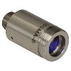 |
These fiber collimation packages are pre-aligned to collimate light from an FC/PC-, FC/APC-, or SMA-terminated fiber. Each collimation package is factory aligned to provide diffraction-limited performance for wavelengths ranging from 405 nm to 4.55 µm. Although it is possible to use the collimator at detuned wavelengths, they will only perform optimally at the design wavelength due to chromatic aberration, which causes the effective focal length of the aspheric lens to have a wavelength dependence. |
| Air-Spaced Doublet, Large Beam Collimators | 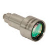 |
For large beam diameters (Ø5.3 - Ø8.5 mm), Thorlabs offers FC/APC, FC/PC, and SMA air-spaced doublet collimators. These collimation packages are pre-aligned at the factory to collimate a laser beam propagating from the tip of an FC or SMA-terminated fiber and provide diffraction-limited performance at the design wavelength. |
| Triplet Collimators |  |
Thorlabs' High Quality Triplet Fiber Collimation packages use air-spaced triplet lenses that offer superior beam quality performance when compared to aspheric lens collimators. The benefits of the low-aberration triplet design include an M2 term closer to 1 (Gaussian), less divergence, and less wavefront error. |
| Achromatic Collimators for Multimode Fiber | 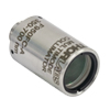 |
Thorlabs' High-NA Achromatic Collimators pair a meniscus lens with an achromatic doublet for high performance across the visible to near-infrared spectrum with low spherical aberration. Designed for use with high-NA multimode fiber, these collimators are ideal for Optogenetics and Fiber Photometry applications. |
| Reflective Collimators |  |
Thorlabs' metallic-coated Reflective Collimators are based on a 90° off-axis parabolic mirror. Mirrors, unlike lenses, have a focal length that remains constant over a broad wavelength range. Due to this intrinsic property, a parabolic mirror collimator does not need to be adjusted to accommodate various wavelengths of light, making them ideal for use with polychromatic light. Our fixed reflective collimators are recommended for collimating single and multimode fiber and coupling into multimode fiber. These collimators are available with UV-enhanced aluminum or protected silver reflective coatings and with FC/PC, FC/APC, or SMA connector compatibility. |
| Compact Reflective Collimators | 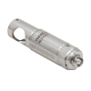 |
Thorlabs' Compact Reflective Collimators incorporate a 90° off-axis parabolic mirror with a protected silver coating. Because the focal length is independent of wavelength for an off-axis parabolic mirror, they are ideal for use with polychromatic light. Our fixed reflective collimators are recommended for collimating single and multimode fiber and coupling into multimode fiber. These collimators are directly compatible with our 16 mm cage system. They are available with FC/PC, FC/APC, or SMA connector inputs. |
| Adjustable Reflective Collimators | 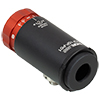 |
Thorlabs' Adjustable Focus Reflective Collimators use a 90° off-axis parabolic (OAP) mirror with a protected silver coating to collimate light from a fiber or couple light into a fiber. The adjustable fiber-to-OAP distance, combined with the OAP having a constant focal length across wavelengths, makes these collimators ideal for optimizing collimation or coupling of polychromatic light with single mode or multimode fiber. These adjustable collimators have a 15.0 mm or 33.0 mm reflected focal length and are available with FC/PC, FC/APC, or SMA connectors. |
| Polaris Kinematic, Fixed Focus Collimators |  |
Polaris® Kinematic, Fixed Focus Collimators combine the high-quality beam output of our fixed focus collimation packages with the remarkable mechanical properties of our Polaris® mounts, making them the ultimate solution for fiber collimation applications requiring stringent long-term alignment stability. These fiber collimation packages are pre-aligned to collimate light from an FC/PC-terminated fiber with diffraction-limited performance at one of four alignment wavelengths between 532 nm and 850 nm. |
| FiberPorts | 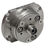 |
These compact, ultra-stable FiberPort micropositioners provide an easy-to-use, stable platform for coupling light into and out of FC/PC, FC/APC, or SMA terminated optical fibers. It can be used with single mode, multimode, or PM fibers and can be mounted onto a post, stage, platform, or laser. The built-in aspheric or achromatic lens is available with five different AR coatings and has five degrees of alignment adjustment (3 translational and 2 pitch). The compact size and long-term alignment stability make the FiberPort an ideal solution for fiber coupling, collimation, or incorporation into OEM systems. |
| Adjustable Fiber Collimators |  |
These collimators are designed to connect onto the end of an FC/PC, FC/APC, or SMA connector and contain an AR-coated aspheric lens. The distance between the aspheric lens and the tip of the fiber can be adjusted to compensate for focal length changes or to recollimate the beam at the wavelength and distance of interest. |
| Achromatic Fiber Collimators with Adjustable Focus |  |
Thorlabs' Achromatic Fiber Collimators with Adjustable Focus are designed with an effective focal length (EFL) of 20 mm, 40 mm, or 80 mm, have optical elements broadband AR coated for one of three wavelength ranges, and are available with FC/PC, FC/APC, or SMA905 connectors. A four-element, air-spaced lens design produces superior beam quality (M2 close to 1) and less wavefront error when compared to aspheric lens collimators. These collimators can be used for free-space coupling into a fiber, collimation of output from a fiber, or in pairs for collimator-to-collimator coupling over long distances, which allows the beam to be manipulated prior to entering the second collimator. |
| Zoom Fiber Collimators |  |
These collimators provide a variable focal length between 6 and 18 mm, while maintaining the collimation of the beam. As a result, the size of the beam can be changed without altering the collimation. This universal device saves time previously spent searching for the best suited fixed fiber collimator and has a very broad range of applications. They are offered with FC/PC, FC/APC, or SMA905 connectors with three different antireflection wavelength ranges to choose from. |
| Single Mode Pigtailed Collimators |  |
Our single mode pigtailed collimators come with one meter of fiber, consist of an AR-coated aspheric lens pre-aligned with respect to a fiber, and are collimated at one of eight wavelengths: 532 nm, 633 nm, 780 nm, 850 nm, 1030 nm, 1064 nm, 1310 nm, or 1550 nm. Although it is possible to use the collimator at any wavelength within the coating range, the coupling loss will increase as the wavelength is detuned from the design wavelength. |
| Polarization Maintaining Pigtailed Collimators |  |
Our polarization maintaining pigtailed collimators come with one meter of fiber, consist of an AR-coated aspheric lens pre-aligned with respect to a fiber, and are collimated at one of five wavelengths: 633 nm, 780 nm, 980 nm, 1064 nm, or 1550 nm. Custom wavelengths and connectors are available as well. A line is engraved along the outside of the housing that is parallel to the fast axis. As such, it can be used as a reference when polarized light is launched accordingly. Although it is possible to use the collimator at any wavelength within the coating range, the coupling loss will increase as the wavelength is detuned from the design wavelength. |
| GRIN Fiber Collimators |  |
Thorlabs offers gradient index (GRIN) fiber collimators that are aligned at a variety of wavelengths from 630 to 1550 nm and have either FC terminated, APC terminated, or unterminated fibers. Our GRIN collimators feature a Ø1.8 mm clear aperture, are AR-coated to ensure low back reflection into the fiber, and are coupled to standard single mode or graded-index multimode fibers. |
| GRIN Lenses |  |
These graded-index (GRIN) lenses are AR coated for applications at 630, 830, 1060, 1300, or 1560 nm that require light to propagate through one fiber, then through a free-space optical system, and finally back into another fiber. They are also useful for coupling light from laser diodes into fibers, coupling the output of a fiber into a detector, or collimating laser light. Our GRIN lenses are designed to be used with our Pigtailed Glass Ferrules and GRIN/Ferrule sleeves. |
*See Table G1.1 for the exact focal length at the specified wavelength for each TC06FC Triplet Collimator.
| Table G1.1 Specifications | ||||||||||||
|---|---|---|---|---|---|---|---|---|---|---|---|---|
| Item # | Alignment Wavelength |
Operating Wavelength Rangea |
AR Coatingb |
Waist Diameterc |
Waist Distanced |
Full-Angle Divergencee |
Wavelength- Adjusted Focal Length |
Alignment Fiberf |
Connector Styleg |
NA | Lh | Drawingi |
| TC06FC-405 | 405 nm | 400 - 409 nm | 400 - 650 nm |
1.10 mm | 0.77 mm | 0.027° | 5.80 mm | SM400 | 2.2 mm Wide Key FC/PC |
0.28 | 20.4 mm (0.80") |
 Click for Details |
| TC06FC-532 | 532 nm | 519 - 543 nm | 400 - 650 nm |
1.11 mm | 0.90 mm | 0.035° | 5.95 mm | 460HP | 20.6 mm (0.81") |
|||
| TC06FC-543 | 543 nm | 528 - 558 nm | 400 - 650 nm |
1.11 mm | 0.91 mm | 0.036° | 5.96 mm | 460HP | 20.5 mm (0.81") |
|||
| TC06FC-633 | 633 nm | 607 - 659 nm | 400 - 650 nm |
1.12 mm | 0.95 mm | 0.041° | 6.01 mm | SM600 | 20.6 mm (0.81") |
|||
| TC06FC-780 | 780 nm | 742 - 823 nm | 650 - 1050 nm |
1.31 mm | 1.00 mm | 0.044° | 6.06 mm | 780HP | 20.6 mm (0.81") |
|||
| TC06FC-850 | 850 nm | 792 - 902 nm | 650 - 1050 nm |
1.31 mm | 1.01 mm | 0.047° | 6.08 mm | 780HP | 20.7 mm (0.81") |
|||
| TC06FC-980 | 980 nm | 907 - 1064 nm | 650 - 1050 nm |
1.31 mm | 1.03 mm | 0.055° | 6.11 mm | SM980-5.8-125 | 20.6 mm (0.81") |
|||
| TC06FC-1064 | 1060 nm | 974 - 1157 nm | 1050 - 1650 nm |
1.33 mm | 1.04 mm | 0.058° | 6.12 mm | SM980-5.8-125 | 20.7 mm (0.81") |
|||
| TC06FC-1310 | 1310 nm | 1125 - 1479 nm | 1050 - 1650 nm |
1.11 mm | 1.07 mm | 0.085° | 6.15 mm | SMF-28e+ | 20.7 mm (0.82") |
|||
| TC06FC-1550 | 1550 nm | 1325 - 1730 nm | 1050 - 1650 nm |
1.12 mm | 1.10 mm | 0.101° | 6.18 mm | SMF-28e+ | 20.7 mm (0.82") |
|||
| TC06FC-2000 | 2 µm | 1765 - 2156 nm | 1970 - 2030 nm |
1.22 mm | 1.14 mm | 0.119° | 6.24 mm | SM2000 | 20.8 mm (0.82") |
|||
*See Table G2.1 for the exact focal length at the specified wavelength for each TC06APC Triplet Collimator.
| Table G2.1 Specifications | ||||||||||||
|---|---|---|---|---|---|---|---|---|---|---|---|---|
| Item # | Alignment Wavelength |
Operating Wavelength Rangea |
AR Coatingb |
Waist Diameterc |
Waist Distanced |
Full-Angle Divergencee |
Wavelength- Adjusted Focal Length |
Alignment Fiberf |
Connector Typeg |
NA | Lh | Drawingi |
| TC06APC-405 | 405 nm | 400 - 409 nm | 400 - 650 nm |
1.10 mm | 0.77 mm | 0.027° | 5.80 mm | SM400 | 2.2 mm Wide Key FC/APC |
0.28 | 20.7 mm (0.81") |
 Click for Details |
| TC06APC-532 | 532 nm | 519 - 543 nm | 400 - 650 nm |
1.11 mm | 0.90 mm | 0.035° | 5.95 mm | 460HP | 20.8 mm (0.82") |
|||
| TC06APC-543 | 543 nm | 528 - 558 nm | 400 - 650 nm |
1.11 mm | 0.91 mm | 0.036° | 5.96 mm | 460HP | 20.8 mm (0.82") |
|||
| TC06APC-633 | 633 nm | 607 - 659 nm | 400 - 650 nm |
1.12 mm | 0.95 mm | 0.041° | 6.01 mm | SM600 | 20.8 mm (0.82") |
|||
| TC06APC-780 | 780 nm | 742 - 823 nm | 650 - 1050 nm |
1.31 mm | 1.00 mm | 0.044° | 6.06 mm | 780HP | 20.9 mm (0.82") |
|||
| TC06APC-850 | 850 nm | 792 - 902 nm | 650 - 1050 nm |
1.31 mm | 1.01 mm | 0.047° | 6.08 mm | 780HP | 20.9 mm (0.82") |
|||
| TC06APC-980 | 980 nm | 907 - 1064 nm | 650 - 1050 nm |
1.31 mm | 1.03 mm | 0.055° | 6.11 mm | SM980-5.8-125 | 20.9 mm (0.82") |
|||
| TC06APC-1064 | 1060 nm | 974 - 1157 nm | 1050 - 1650 nm |
1.33 mm | 1.04 mm | 0.058° | 6.12 mm | SM980-5.8-125 | 20.9 mm (0.82") |
|||
| TC06APC-1310 | 1310 nm | 1125 - 1479 nm | 1050 - 1650 nm |
1.11 mm | 1.07 mm | 0.085° | 6.15 mm | SMF-28e+ | 21.0 mm (0.83") |
|||
| TC06APC-1550 | 1550 nm | 1325 - 1730 nm | 1050 - 1650 nm |
1.12 mm | 1.10 mm | 0.101° | 6.18 mm | SMF-28e+ | 21.0 mm (0.83") |
|||
| TC06APC-2000 | 2 µm | 1765 - 2156 nm | 1970 - 2030 nm |
1.22 mm | 1.14 mm | 0.119° | 6.24 mm | SM2000 | 21.0 mm (0.83") |
|||
*See Table G3.1 for the exact focal length at the specified wavelength for each TC12FC Triplet Collimator.
| Table G3.1 Specifications | ||||||||||||
|---|---|---|---|---|---|---|---|---|---|---|---|---|
| Item # | Alignment Wavelength |
Operating Wavelength Rangea |
AR Coatingb |
Waist Diameterc |
Waist Distanced |
Full-Angle Divergencee |
Wavelength- Adjusted Focal Length |
Alignment Fiberf |
Connector Styleg |
NA | Lh | Drawingi |
| TC12FC-405 | 405 nm | 404 - 406 nm | 400 - 650 nm |
2.12 mm | 7.65 mm | 0.014° | 11.14 mm | SM400 | 2.2 mm Wide Key FC/PC |
0.28 | 25.3 mm (0.99") |
 Click for Details |
| TC12FC-532 | 532 nm | 529 - 535 nm | 400 - 650 nm |
2.20 mm | 8.39 mm | 0.017° | 11.75 mm | 460HP | 25.7 mm (1.01") |
|||
| TC12FC-543 | 543 nm | 539 - 547 nm | 400 - 650 nm |
2.20 mm | 8.40 mm | 0.017° | 11.80 mm | 460HP | 25.8 mm (1.01") |
|||
| TC12FC-633 | 633 nm | 625 - 640 nm | 400 - 650 nm |
2.24 mm | 9.57 mm | 0.021° | 12.00 mm | SM600 | 25.0 mm (0.98") |
|||
| TC12FC-780 | 780 nm | 768 - 792 nm | 650 - 1050 nm |
2.64 mm | 9.79 mm | 0.024° | 12.19 mm | 780HP | 25.1 mm (0.99") |
|||
| TC12FC-850 | 850 nm | 832 - 867 nm | 650 - 1050 nm |
2.66 mm | 9.97 mm | 0.023° | 12.27 mm | 780HP | 25.2 mm (0.99") |
|||
| TC12FC-980 | 980 nm | 953 - 1008 nm | 650 - 1050 nm |
2.66 mm | 9.95 mm | 0.027° | 12.36 mm | SM980-5.8-125 | 25.3 mm (1.00") |
|||
| TC12FC-1064 | 1060 nm | 1030 - 1100 nm | 1050 - 1650 nm |
2.70 mm | 10.00 mm | 0.029° | 12.38 mm | SM980-5.8-125 | 25.3 mm (1.00") |
|||
| TC12FC-1310 | 1310 nm | 1230 - 1398 nm | 1050 - 1650 nm |
2.26 mm | 10.11 mm | 0.044° | 12.48 mm | SMF-28e+ | 25.4 mm (1.00") |
|||
| TC12FC-1550 | 1550 nm | 1450 - 1663 nm | 1050 - 1650 nm |
2.27 mm | 10.20 mm | 0.050° | 12.56 mm | SMF-28e+ | 25.5 mm (1.00") |
|||
| TC12FC-2000 | 2 µm | 1880 - 2116 nm | 1970 - 2030 nm |
2.49 mm | 10.48 mm | 0.059° | 12.73 mm | SM2000 | 25.6 mm (1.01") |
|||
*See Table G4.1 for the exact focal length at the specified wavelength for each TC12APC Triplet Collimator.
| Table G4.1 Specifications | ||||||||||||
|---|---|---|---|---|---|---|---|---|---|---|---|---|
| Item # | Alignment Wavelength |
Operating Wavelength Rangea |
AR Coatingb |
Waist Diameterc |
Waist Distanced |
Full-Angle Divergencee |
Wavelength- Adjusted Focal Length |
Alignment Fiberf |
Connector Styleg |
NA | Lh | Drawingi |
| TC12APC-405 | 405 nm | 404 - 406 nm | 400 - 650 nm |
2.12 mm | 7.65 mm | 0.014° | 11.14 mm | SM400 | 2.2 mm Wide Key FC/APC |
0.28 | 25.4 mm (1.00") |
 Click for Details |
| TC12APC-532 | 532 nm | 529 - 535 nm | 400 - 650 nm |
2.20 mm | 8.39 mm | 0.017° | 11.75 mm | 460HP | 26.0 mm (1.02") |
|||
| TC12APC-543 | 543 nm | 539 - 547 nm | 400 - 650 nm |
2.20 mm | 8.40 mm | 0.017° | 11.80 mm | 460HP | 26.0 mm (1.02") |
|||
| TC12APC-633 | 633 nm | 625 - 640 nm | 400 - 650 nm |
2.24 mm | 9.57 mm | 0.021° | 12.00 mm | SM600 | 25.2 mm (0.99") |
|||
| TC12APC-780 | 780 nm | 768 - 792 nm | 650 - 1050 nm |
2.64 mm | 9.79 mm | 0.024° | 12.19 mm | 780HP | 25.3 mm (1.00") |
|||
| TC12APC-850 | 850 nm | 832 - 867 nm | 650 - 1050 nm |
2.66 mm | 9.97 mm | 0.023° | 12.27 mm | 780HP | 25.4 mm (1.00") |
|||
| TC12APC-980 | 980 nm | 953 - 1008 nm | 650 - 1050 nm |
2.66 mm | 9.95 mm | 0.027° | 12.36 mm | SM980-5.8-125 | 25.5 mm (1.00") |
|||
| TC12APC-1064 | 1060 nm | 1030 - 1100 nm | 1050 - 1650 nm |
2.70 mm | 10.00 mm | 0.029° | 12.38 mm | SM980-5.8-125 | 25.5 mm (1.00") |
|||
| TC12APC-1310 | 1310 nm | 1230 - 1398 nm | 1050 - 1650 nm |
2.26 mm | 10.11 mm | 0.044° | 12.48 mm | SMF-28e+ | 25.6 mm (1.01") |
|||
| TC12APC-1550 | 1550 nm | 1450 - 1663 nm | 1050 - 1650 nm |
2.27 mm | 10.20 mm | 0.050° | 12.56 mm | SMF-28e+ | 25.7 mm (1.01") |
|||
| TC12APC-2000 | 2 µm | 1880 - 2116 nm | 1970 - 2030 nm |
2.49 mm | 10.48 mm | 0.059° | 12.73 mm | SM2000 | 25.8 mm (1.02") |
|||
*See Table G5.1 for the exact focal length at the specified wavelength for each TC18FC Triplet Collimator.
| Table G5.1 Specifications | ||||||||||||
|---|---|---|---|---|---|---|---|---|---|---|---|---|
| Item # | Alignment Wavelength |
Operating Wavelength Rangea |
AR Coatingb |
Waist Diameterc |
Waist Distanced |
Full-Angle Divergencee |
Wavelength- Adjusted Focal Length |
Alignment Fiberf |
Connector Styleg |
NA | Lh | Drawingi |
| TC18FC-405 | 405 nm | 400 - 410 nm | 400 - 650 nm |
3.38 mm | 12.32 mm | 0.009° | 17.72 mm | SM400 | 2.2 mm Wide Key FC/PC |
0.28 | 32.7 mm (1.29") |  Click for Details |
| TC18FC-532 | 532 nm | 524 - 542 nm | 400 - 650 nm |
3.34 mm | 12.36 mm | 0.012° | 17.90 mm | 460HP | 32.9 mm (1.29") |
|||
| TC18FC-543 | 543 nm | 534 - 555 nm | 400 - 650 nm |
3.35 mm | 12.49 mm | 0.013° | 17.91 mm | 460HP | 32.9 mm (1.29") | |||
| TC18FC-633 | 633 nm | 619 - 652 nm | 400 - 650 nm |
3.37 mm | 12.56 mm | 0.014° | 17.99 mm | SM600 | 33.0 mm (1.30") | |||
| TC18FC-780 | 780 nm | 762 - 808 nm | 650 - 1050 nm |
3.92 mm | 12.65 mm | 0.015° | 18.09 mm | 780HP | 33.0 mm (1.30") | |||
| TC18FC-850 | 850 nm | 821 - 879 nm | 650 - 1050 nm |
3.91 mm | 12.72 mm | 0.016° | 18.12 mm | 780HP | 33.1 mm (1.30") |
|||
| TC18FC-980 | 980 nm | 943 - 1022 nm | 650 - 1050 nm |
3.91 mm | 12.73 mm | 0.019° | 18.17 mm | SM980-5.8-125 | 33.1 mm (1.30") | |||
| TC18FC-1064 | 1060 nm | 1027 - 1116 nm | 1050 - 1650 nm |
3.98 mm | 12.76 mm | 0.020° | 18.20 mm | SM980-5.8-125 | 33.1 mm (1.30") | |||
| TC18FC-1310 | 1310 nm | 1236 - 1400 nm | 1050 - 1650 nm |
3.31 mm | 12.83 mm | 0.029° | 18.28 mm | SMF-28e+ | 33.2 mm (1.31") | |||
| TC18FC-1550 | 1550 nm | 1465 - 1648 nm | 1050 - 1650 nm |
3.33 mm | 12.91 mm | 0.034° | 18.36 mm | SMF-28e+ | 33.3 mm (1.31") | |||
| TC18FC-2000 | 2 µm | 1920 - 2082 nm | 1970 - 2030 nm |
3.63 mm | 13.07 mm | 0.040° | 18.52 mm | SM2000 | 33.5 mm (1.32") |
|||
*See Table G6.1 for the exact focal length at the specified wavelength for each TC18APC Triplet Collimator.
| Table G6.1 Specifications | ||||||||||||
|---|---|---|---|---|---|---|---|---|---|---|---|---|
| Item # | Alignment Wavelength |
Operating Wavelength Rangea |
AR Coatingb |
Waist Diameterc |
Waist Distanced |
Full-Angle Divergencee |
Wavelength- Adjusted Focal Length |
Alignment Fiberf |
Connector Styleg |
NA | Lh | Drawingi |
| TC18APC-405 | 405 nm | 400 - 410 nm | 400 - 650 nm |
3.38 mm | 12.32 mm | 0.009° | 17.72 mm | SM400 | 2.2 mm Wide Key FC/APC |
0.28 | 32.9 mm (1.30") | 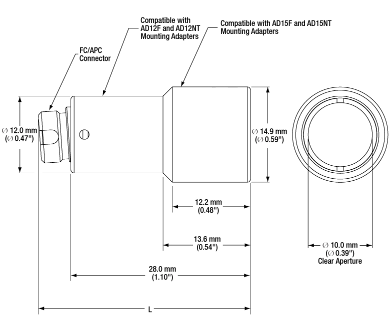 Click for Details |
| TC18APC-532 | 532 nm | 524 - 542 nm | 400 - 650 nm |
3.34 mm | 12.36 mm | 0.012° | 17.90 mm | 460HP | 33.1 mm (1.30") |
|||
| TC18APC-543 | 543 nm | 534 - 555 nm | 400 - 650 nm |
3.35 mm | 12.49 mm | 0.013° | 17.91 mm | 460HP | 33.1 mm (1.30") | |||
| TC18APC-633 | 633 nm | 619 - 652 nm | 400 - 650 nm |
3.37 mm | 12.56 mm | 0.014° | 17.99 mm | SM600 | 33.2 mm (1.31") | |||
| TC18APC-780 | 780 nm | 762 - 808 nm | 650 - 1050 nm |
3.92 mm | 12.65 mm | 0.015° | 18.09 mm | 780HP | 33.3 mm (1.31") | |||
| TC18APC-850 | 850 nm | 821 - 879 nm | 650 - 1050 nm |
3.91 mm | 12.72 mm | 0.016° | 18.12 mm | 780HP | 33.3 mm (1.31") |
|||
| TC18APC-980 | 980 nm | 943 - 1022 nm | 650 - 1050 nm |
3.91 mm | 12.73 mm | 0.019° | 18.17 mm | SM980-5.8-125 | 33.3 mm (1.31") | |||
| TC18APC-1064 | 1060 nm | 1027 - 1116 nm | 1050 - 1650 nm |
3.98 mm | 12.76 mm | 0.020° | 18.20 mm | SM980-5.8-125 | 33.4 mm (1.31") | |||
| TC18APC-1310 | 1310 nm | 1236 - 1400 nm | 1050 - 1650 nm |
3.31 mm | 12.83 mm | 0.029° | 18.28 mm | SMF-28e+ | 33.4 mm (1.32") | |||
| TC18APC-1550 | 1550 nm | 1465 - 1648 nm | 1050 - 1650 nm |
3.33 mm | 12.91 mm | 0.034° | 18.36 mm | SMF-28e+ | 33.5 mm (1.32") | |||
| TC18APC-2000 | 2 µm | 1920 - 2082 nm | 1970 - 2030 nm |
3.63 mm | 13.07 mm | 0.040° | 18.52 mm | SM2000 | 33.7 mm (1.33") |
|||
*See Table G7.1 for the exact focal length at the specified wavelength for each TC25FC Triplet Collimator.
| Table G7.1 Specifications | ||||||||||||
|---|---|---|---|---|---|---|---|---|---|---|---|---|
| Item # | Alignment Wavelength |
Operating Wavelength Rangea |
AR Coatingb |
Waist Diameterc |
Waist Distanced |
Full-Angle Divergencee |
Wavelength- Adjusted Focal Length |
Alignment Fiberf |
Connector Styleg |
NA | Lh | Drawingi |
| TC25FC-405 | 405 nm | 379 - 429 nm | 400 - 650 nm |
4.70 mm | 16.86 mm | 0.006° | 24.77 mm | SM400 | 2.2 mm Wide Key FC/PC |
0.25 | 42.7 mm (1.68") |
 Click for Details |
| TC25FC-532 | 532 nm | 520 - 545 nm | 400 - 650 nm |
4.65 mm | 16.98 mm | 0.008° | 24.90 mm | 460HP | 42.8 mm (1.68") |
|||
| TC25FC-543 | 543 nm | 531 - 557 nm | 400 - 650 nm |
4.64 mm | 16.99 mm | 0.009° | 24.91 mm | 460HP | 42.8 mm (1.68") |
|||
| TC25FC-633 | 633 nm | 616 - 652 nm | 400 - 650 nm |
4.67 mm | 17.06 mm | 0.010° | 24.98 mm | SM600 | 42.8 mm (1.69") |
|||
| TC25FC-780 | 780 nm | 761 - 802 nm | 650 - 1050 nm |
5.42 mm | 17.15 mm | 0.010° | 25.08 mm | 780HP | 42.9 mm (1.69") |
|||
| TC25FC-850 | 850 nm | 827 - 874 nm | 650 - 1050 nm |
5.44 mm | 17.24 mm | 0.011° | 25.12 mm | 780HP | 43.0 mm (1.69") |
|||
| TC25FC-980 | 980 nm | 953 - 1011 nm | 650 - 1050 nm |
5.40 mm | 17.25 mm | 0.013° | 25.19 mm | SM980-5.8-125 | 43.0 mm (1.69") |
|||
| TC25FC-1064 | 1060 nm | 1035 - 1097 nm | 1050 - 1650 nm |
5.49 mm | 17.29 mm | 0.014° | 25.23 mm | SM980-5.8-125 | 43.1 mm (1.70") |
|||
| TC25FC-1310 | 1310 nm | 1262 - 1361 nm | 1050 - 1650 nm |
4.58 mm | 17.41 mm | 0.021° | 25.35 mm | SMF-28e+ | 43.2 mm (1.70") |
|||
| TC25FC-1550 | 1550 nm | 1500 - 1603 nm | 1050 - 1650 nm |
4.65 mm | 17.54 mm | 0.024° | 25.49 mm | SMF-28e+ | 43.3 mm (1.71") |
|||
| TC25FC-2000 | 2 µm | 1958 - 2044 nm | 1970 - 2030 nm |
5.04 mm | 17.84 mm | 0.029° | 25.79 mm | SM2000 | 43.6 mm (1.72") |
|||
*See Table G8.1 for the exact focal length at the specified wavelength for each TC25APC Triplet Collimator.
| Table G8.1 Specifications | ||||||||||||
|---|---|---|---|---|---|---|---|---|---|---|---|---|
| Item # | Alignment Wavelength |
Operating Wavelength Rangea |
AR Coatingb |
Waist Diameterc |
Waist Distanced |
Full-Angle Divergencee |
Wavelength- Adjusted Focal Length |
Alignment Fiberf |
Connector Styleg |
NA | Lh | Drawingi |
| TC25APC-405 | 405 nm | 379 - 429 nm | 400 - 650 nm |
4.70 mm | 16.86 mm | 0.006° | 24.77 mm | SM400 | 2.2 mm Wide Key FC/APC |
0.25 | 42.9 mm (1.69") |
 Click for Details |
| TC25APC-532 | 532 nm | 520 - 545 nm | 400 - 650 nm |
4.65 mm | 16.98 mm | 0.008° | 24.90 mm | 460HP | 43.0 mm (1.69") |
|||
| TC25APC-543 | 543 nm | 531 - 557 nm | 400 - 650 nm |
4.64 mm | 16.99 mm | 0.009° | 24.91 mm | 460HP | 43.0 mm (1.69") |
|||
| TC25APC-633 | 633 nm | 616 - 652 nm | 400 - 650 nm |
4.67 mm | 17.06 mm | 0.010° | 24.98 mm | SM600 | 43.1 mm (1.70") |
|||
| TC25APC-780 | 780 nm | 761 - 802 nm | 650 - 1050 nm |
5.42 mm | 17.15 mm | 0.010° | 25.08 mm | 780HP | 43.2 mm (1.70") |
|||
| TC25APC-850 | 850 nm | 827 - 874 nm | 650 - 1050 nm |
5.44 mm | 17.24 mm | 0.011° | 25.19 mm | 780HP | 43.2 mm (1.70") |
|||
| TC25APC-980 | 980 nm | 953 - 1011 nm | 650 - 1050 nm |
5.40 mm | 17.25 mm | 0.013° | 25.19 mm | SM980-5.8-125 | 43.2 mm (1.70") |
|||
| TC25APC-1064 | 1060 nm | 1035 - 1097 nm | 1050 - 1650 nm |
5.49 mm | 17.29 mm | 0.014° | 25.23 mm | SM980-5.8-125 | 43.3 mm (1.70") |
|||
| TC25APC-1310 | 1310 nm | 1262 - 1361 nm | 1050 - 1650 nm |
4.58 mm | 17.41 mm | 0.021° | 25.35 mm | SMF-28e+ | 43.4 mm (1.71") |
|||
| TC25APC-1550 | 1550 nm | 1500 - 1603 nm | 1050 - 1650 nm |
4.65 mm | 17.54 mm | 0.024° | 25.49 mm | SMF-28e+ | 43.5 mm (1.71") |
|||
| TC25APC-2000 | 2 µm | 1958 - 2044 nm | 1970 - 2030 nm |
5.04 mm | 17.84 mm | 0.029° | 25.79 mm | SM2000 | 43.8 mm (1.73") |
|||