 Products Home / Motorized Stages / Motorized Rotation Stages and Mounts / Motorized Precision Rotation Stage with DC Servo Motor
Motorized Precision Rotation Stage with DC Servo Motor

- Continuous 360° Motorized Rotation
- Rotational Velocity: 25 Degree/Second
- Tapped Platform for Mounting Prisms or Other Optics
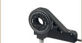
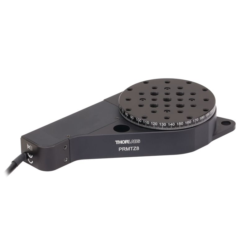
PRMTZ8
Motorized Continuous
Rotation Stage
Application Idea
PRMTZ8 with PM3 Clamping Arm
and Pellin Broca Prism


Please Wait
| Key Specificationsa | |
|---|---|
| Platform Size | Ø66.2 mm (2.61") |
| Platform Mounting Holes | Eight 6-32 (M4) Sixteen 8-32 (M4) Five 1/4"-20 (M6) |
| Bidirectional Repeatability | ±0.1° |
| Backlash | ±0.3° |
| Max Rotation Velocity | 25 deg/s |
| Horizontal On-Axis Load Capacityb | 15 N (1.5 kg, 3.4 lbs) |
| Repeatable Incremental Motion (Min) | 0.04° |
| Percentage Accuracy | 0.1% |
| Home Location Accuracy | ±0.2° |
| Range | 360° Continuous |
Features
- 25 deg/sec Rotation Velocity
- Mounting Holes for Prism Clamps (Sold Below) or Other Optomechanics
- 1° Graduations on Main Dial
- Compact Design is Only 25 mm Tall
- Home Limit Switch For Precise 0° Locating within ±0.2°
- Recommended Driver: KDC101 DC Servo Controller
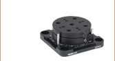
The PRMTZ8 is a compact, DC servo motorized 360° rotation stage with a tapped platform. The user can measure the angular displacement of the platform by using the Vernier scale (5 arcmin resolution) in conjunction with the graduation marks that are marked on the rotating platform in 1° increments. This rotation stage is also equipped with a home limit switch to facilitate automated rotation to the precise 0° position, allowing absolute angular positioning thereafter. The limit switch is designed to allow continuous rotation of the stage over multiple 360° cycles.
The KDC101 DC Servo Controller, sold separately below, is the ideal companion for achieving smooth, continuous motion that can be automated via the software interface. The stage, controller, and KPS101* or KPS201 power supply are available for purchase together as a bundle (Item #s KPRMTE and KPRMTE/M respectively).
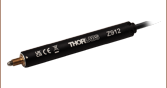
The PRMTZ8 is supplied with 430 mm (16.93") of cable. An 2.5 m (8 ft) extension cable (PAA632) is available separately.
*This previous-generation item is not available for individual purchase. If a replacement is needed, the KPS201 Power Supply can be used.
| Motor Specifications | |
|---|---|
| Motor Type | DC Servo |
| Nominal Voltage | 6 V |
| No Load Speed | 6560 rpm |
| No Load Current | 7.43 mA |
| Nominal Speed | 1050 rpm |
| Nominal Torque (Maximum Continuous Torque) | 1.26 mN•m |
| Nominal Current (Maximum Continuous Current) | 0.156 A |
| Stall Torque | 1.54 mN•m |
| Starting Current | 0.184 A |
| Maximum Efficiency | 65% |
| Terminal Resistance | 32.7 Ω |
| Terminal Inductance | 0.607 mH |
| Torque Constant | 8.38 mN•m/A |
| Speed Constant | 1140 rpm/V |
| Speed / Torque Gradient | 4450 rpm/mN•m |
| Mechanical Time Constant | 13.9 ms |
| Rotor Inertia | 0.298 g•cm2 |
| Stage Specifications | |
|---|---|
| Translation and Motion Parameters | |
| Travel Range | 360° Continuous |
| Bidirectional Repeatabilitya | ±0.1° |
| Backlashb | ±0.3° |
| Max Rotation Velocity | 25 deg/s |
| Calculated Resolution | 2 arcsec (0.0005°) |
| Horizontal On-Axis Load Capacityc | 15 N (1.5 kg, 3.4 lbs) |
| Min Repeatable Incremental Motiond | 0.04° |
| Percentage Accuracy | 0.1% |
| Home Location Accuracy | ±0.2° |
| Wobble | 200 µrad |
| Physical | |
| Platform Size | Ø66.2 mm (2.61") |
| Platform Mounting Holes | Eight 6-32 (M4) Sixteen 8-32 (M4) Five 1/4"-20 (M6) |
| Dimensions | 137.4 mm x 73.3 mm x 25 mm (5.41" x 2.88" x 0.98") |
| Weight | 0.38 kg (0.84 lbs) |
| Cable Length | 430 mm (16.93") |
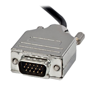
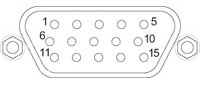
Motor Connector Pin Out
| Pin | Description | Pin | Description |
|---|---|---|---|
| 1 | Ground/Return | 9 | Ident Resistora |
| 2 | Reserved For Future Use | 10 | Vcc/Ident Resistor |
| 3 | Limit Switch | 11 | Encoder Channel B |
| 4 | Reserved For Future Use | 12 | Reserved For Future Use |
| 5 | Motor (+) | 13 | Encoder Channel A |
| 6 | Reserved For Future Use | 14 | Ident EEPROM |
| 7 | Motor (-) | 15 | Ident EEPROM |
| 8 | Reserved For Future Use | - | - |
D-Type Male
Software
Kinesis Version 1.14.53
The Kinesis Software Package, which includes a GUI for control of Thorlabs' Kinesis system controllers.
Also Available:
- Communications Protocol
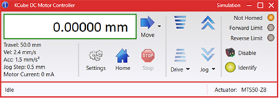
Figure 58A Kinesis GUI Screen
Thorlabs offers the Kinesis® software package to drive our wide range of motion controllers. The software can be used to control devices in the Kinesis family, which covers a wide variety of motion controllers ranging from small, low-powered, single-channel drivers (such as the K-Cubes®) to high-power, multi-channel benchtop units and modular 19" rack nanopositioning systems (the MMR60x Rack System).
The Kinesis Software features .NET controls which can be used by 3rd party developers working in the latest C#, Visual Basic, LabVIEW™, or any .NET compatible languages to create custom applications. Low-level DLL libraries are included for applications not expected to use the .NET framework and APIs are included with each install. A Central Sequence Manager supports integration and synchronization of all Thorlabs motion control hardware.
By providing this common software platform, Thorlabs has ensured that users can mix and match any of our motion control devices in a single application, while only having to learn a single set of software tools. In this way, it is perfectly feasible to combine any of the controllers from single-axis to multi-axis systems and control all from a single, PC-based unified software interface.
The software package allows two methods of usage: graphical user interface (GUI) utilities for direct interaction with and control of the controllers 'out of the box', and a set of programming interfaces that allow custom-integrated positioning and alignment solutions to be easily programmed in the development language of choice.
Reading a Vernier Scale on a Linear Main Scale
Vernier scales are typically used to add precision to standard, evenly divided scales (such as the scales on Thorlabs' rotation, goniometric, or translation mounts). A vernier scale has found common use in many precision measurement instruments, the most common being calipers and micrometers. The vernier scale uses two scales side-by-side: the main scale and the vernier scale. The direct vernier scale has a slightly smaller spacing between its tick marks owing to the vernier scale having N ticks for every N - 1 ticks on the main scale. Hence, the lines on the main scale will not line up with all the lines on the vernier scale. Only one line from the vernier scale will match well with one line of the main scale, and that is the trick to reading a vernier scale.
Figures 130A through 130C show a linear vernier scale system for three different situations. In each case, the scale on the left is the main scale, while the small scale on the right is the vernier scale. When reading a vernier scale, the main scale is used for the gross number, and the vernier scale gives the precision value. In this manner, a standard ruler or micrometer can become a precision instrument.
The 0 on the vernier scale is the "pointer" (marked by a red arrow in Figures 130A through 130E) and will indicate the main scale reading. In Figure 130A we see the pointer is lined up directly with the 75.6 line. Notice that the only other vernier scale tick mark that lines up well with the main scale is 10. Since the pointer lines up with the main scale’s 75.6, the reading from Figure 130A is 75.60 (in whatever units the instrument measures).
That is essentially all there is to reading a vernier scale. It's a very straightforward way of increasing the precision of a measurement instrument. To expound, let’s look at Figure 130B. Here we see that the pointer is no longer aligned with a line on the main scale, but instead it is slightly above 75.6 and below 75.7; thus, the gross measurement is 75.6. The first vernier line that coincides with a main scale line is the 5, shown with a blue arrow. The vernier scale gives the final digit of precision; since the 5 is aligned to the main scale, the precision measurement for Figure 130B is 75.65.
Since this vernier scale is 10% smaller than the main scale, moving the vernier scale by 1/10 of the main scale will align the next vernier marking. This asks the obvious question: what if the measurement is within the 1/10 precision of the vernier scale? Figure 130C shows just this. Again, the pointer line is in between 75.6 and 75.7, yielding the gross measurement of 75.6. If we look closely, we see that the vernier scale 7 (marked with a blue arrow) is very closely aligned to the main scale, giving a precision measurement of 75.67. However, the vernier scale 7 is very slightly above the main scale mark, and we can see that the vernier scale 8 (directly above 7) is slightly below its corresponding main scale mark. Hence, the scale on Figure 130C could be read as 75.673 ± 0.002. A reading error of about 0.002 would be appropriate for
this instrument.
Click to Enlarge
Figure 130A An example of how to read a vernier scale. The red arrow indicates what is known as the pointer. Since the tick mark labeled 10 on the vernier scale aligns with one of the tick marks on the main scale, this vernier scale is reading 75.60 (in whatever units the instrument measures).
Click to Enlarge
Figure 130B The red arrow indicates the pointer and the blue arrow indicates the vernier line that matches the main scale. This scale reads 75.65.
Click to Enlarge
Figure 130C The red arrow indicates the pointer, and the blue arrow indicates the vernier line that matches the main scale. This scale reads 75.67 but can be accurately read as
75.673 ± 0.002.
Reading a Vernier Scale on a Rotating Main Scale
The vernier scale may also be used on rotating scales where the main scale and vernier scale do not share units. Figures 130D and 130F show a vernier scale system for two different situations where the main scale is given in degrees and the vernier scale has ticks every 5 arcmin (60 arcmin = 1°). In each case, the scale on the top is the main scale, while the small scale on the bottom is the vernier scale.
In Figure 130D we see the pointer is lined up directly with the 341° line. Notice that the only other vernier scale tick marks that line up well with the main scale are ±60 arcmin. Since the pointer lines up with the main scale at 341°, the reading from Figure 130D is 341.00°.
There are two ways to determine the reading if the zero on the vernier scale line is between two lines of the main scale. For the first method, take the line on the left side of the pointer on the vernier scale and subtract that value (in arcmin) from the value on the main scale that is to the right on the main scale. As an example, in Figure 130E the vernier pointer is between 342° and 343°; using the left blue arrow of the vernier scale results in
As we've seen here, vernier scales add precision to a standard scale measurement. While it takes a bit of getting used to, with a little practice, reading these scales is fairly straightforward. Vernier scales, whether they are direct or retrograde*, are read in the same fashion.
*A retrograde vernier scale has a larger spacing between its tick marks with N ticks for every N + 1 ticks on the main scale.
Click to Enlarge
Figure 130D An example of a vernier scale where the main scale and the vernier scale are in different units (degrees and arcmins, respectively). The red arrow indicates the pointer. This scale reads 341.00°.
Click to Enlarge
Figure 130E The red arrow indicates the pointer and the blue arrows give the precision value from the vernier scale.
This scale reads 342.75°.
| Posted Comments: | |
Flavien Beffara
(posted 2024-10-04 15:02:39.647) I am trying to control a PRMTZ8/M with a KDC101 controller using Python. I used the code provided on GitHub titled "KDC101_Power_Meter_Insight_Code.py". The code compiles fine. Unfortunately, the stage does not rotate to the defined real angle value using JogMode like in the youtube video. I do not understand why it is moving slightly and stops. If I try to increase the value in "StepSize" to Decimal(30) it reaches an error. Could you please help me figure out what is the problem with the code ?
Thank you very much in advance.
Best regards. dnewnham
(posted 2024-10-10 10:24:52.0) Thank you for your inquiry I will reach out to you directly to discuss your issue. dnewnham
(posted 2024-10-10 10:24:52.0) Thank you for your inquiry I will reach out to you directly to discuss your issue. Benquan Li
(posted 2023-06-26 12:35:24.07) hello,
We're trying to design a machine using this part.
Could you please provide a solidwork model of 2020version?
My SW cannot open a future version of this model:
https://www.thorlabs.com/thorproduct.cfm?partnumber=PRMTZ8
thank you so much
Best,
Benquan Li
Atia Vision
Campbell CA fguzman
(posted 2023-06-28 04:06:54.0) Thanks for your enquiry. Unfortunately, it is not possible to create older versions of files, nor is it possible to roll back a version of Solidworks. We post a selection of files which can be used by almost anyone which should be appropriate in situations like this. The HTML files (eDrawings) are for customers who may not have any access to software which can open 3D model files. Step files, can be opened in older versions of Solidworks but may have graphical issues if the parts are too complex for the older SW version. I will contact you to further discuss this. user
(posted 2022-10-21 15:47:49.6) How slowly can I rotate the stage in degrees/sec with the kinesis software? jgreschler
(posted 2022-10-28 03:46:05.0) Thank you for reaching out to Thorlabs. Unfortunately we do not have a measured spec for this value currently. Additional specifications and data can be requested by emailing techsupport@thorlabs.com. Michael McGivney
(posted 2022-08-10 10:36:18.407) Hi,
Can you please provide additional details about the maximum loads the PRMTZ8 rotation stage can handle? I am currently designing a test set up and want to be sure the stage can handle the weight I need to place on top of it.
Thank you,
Michael McGivney cwright
(posted 2022-08-12 04:11:50.0) Response from Charles at Thorlabs: Thank you for your query. The load capacity of this stage is specified as 1.5 kg, which assumes the load is centred on the top plate and the stage is flat on the table. A member of technical support will reach out to you to discuss your application and position of the load. Sudhan Bhadade
(posted 2019-08-08 06:51:39.933) Hello, I am using the KDC101 cube with .NET in Labview. I have established a connection with the Kinesis interface using the .dll files. When I attempt to connect to the cube, I receive an error saying "No suitable devices found." When I use the Kinesis app, I can connect with the cube and use all the functions to power a rotational stage, but it fails to connect to my Labview VI. Can I please get some help with this? rmiron
(posted 2019-08-08 10:37:24.0) Response from Radu at Thorlabs: Hello Sudhan. Have you set the SerialNumber property node before attempting to connect? If so, have you made sure to use KDC101's serial number?(as opposed to the stage's) Unfortunately, it sometimes (rarely) happens that the number printed on the cube is different from the one programmed into the unit. That is why it might be worth checking what serial number is shown by Kinesis. I will contact you directly in case these questions are not helpful. paulbertier7
(posted 2018-04-13 14:20:09.58) Hello,
What is the minimum angle step?
Cheers,
Paul bhallewell
(posted 2018-04-20 09:19:03.0) Response from Ben at Thorlabs: Thank you for your feedback, Paul. We state a Minimum Repeatable Incremental Motion of 0.04 degrees in the specs table. maheshswami
(posted 2018-02-15 02:02:56.527) Does it have a through hole/clear axis if the tapped platform is removed. bhallewell
(posted 2018-02-21 03:42:21.0) Response from Ben at Thorlabs: The top plate is a feature of a single moving world assembly & so you can't remove the top plate & use the stage. This stage is designed as a rotation stage as opposed to an optics rotator. For a through hole option, I'd recommend taking a look at our PRM1Z8.
https://www.thorlabs.com/newgrouppage9.cfm?objectgroup_ID=2875
Our K10CR1 stepper actuated optics rotator with integrated controller may also be of interest to you.
https://www.thorlabs.com/newgrouppage9.cfm?objectgroup_ID=8750&pn=K10CR1 |
Rotation Mount and Stage Selection Guide
Thorlabs offers a wide variety of manual and motorized rotation mounts and stages. Rotation mounts are designed with an inner bore to mount a Ø1/2", Ø1", or Ø2" optic, while rotation stages are designed with mounting taps to attach a variety of components or systems. Motorized options are powered by a DC Servo motor, 2 phase stepper motor, piezo inertia motor, or an Elliptec™ resonant piezo motor. Each offers 360° of continuous rotation.
Manual Rotation Mounts
| Rotation Mounts for Ø1/2" Optics | |||||||
|---|---|---|---|---|---|---|---|
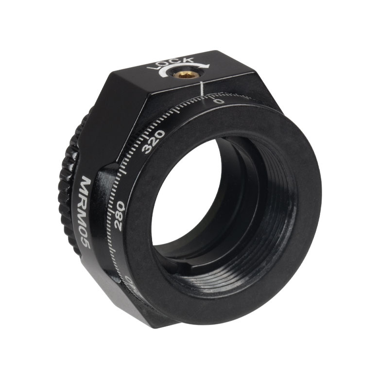
| Item # | MRM05(/M) | RSP05(/M) | CRM05 | PRM05(/M)a | SRM05 | KS05RS | CT104 |
| Click Photo to Enlarge |
 |
 |
 |
 |
 |
 |
 |
| Features | Mini Series | Standard | External SM1 (1.035"-40) Threads |
Micrometer | 16 mm Cage-Compatible | ±4° Kinematic Tip/Tilt Adjustment Plus Rotation | Compatible with 30 mm Cage Translation Stages and 1/4" Translation Stagesb |
| Additional Details | |||||||
| Rotation Mounts for Ø1" Optics | ||||||||
|---|---|---|---|---|---|---|---|---|
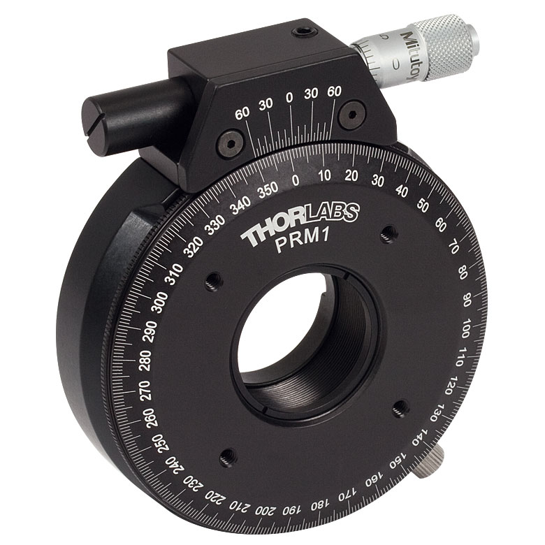
| Item # | RSP1(/M) | LRM1 | RSP1D(/M) | DLM1(/M) | CLR1(/M) | RSP1X15(/M) | RSP1X225(/M) | PRM1(/M)a |
| Click Photo to Enlarge |
 |
 |
 |
 |
 |
 |
|
 |
| Features | Standard | External SM1 (1.035"-40) Threads |
Adjustable Zero | Two Independently Rotating Carriages | Rotates Optic Within Fixed Lens Tube System |
Continuous 360° Rotation or 15° Increments |
Continuous 360° Rotation or 22.5° Increments |
Micrometer |
| Additional Details | ||||||||
| Rotation Mounts for Ø1" Optics | ||||||
|---|---|---|---|---|---|---|
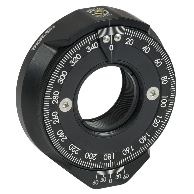
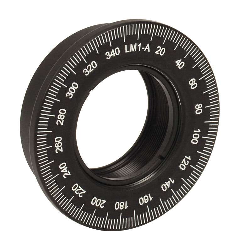
| Item # | LM1-A & LM1-B(/M) |
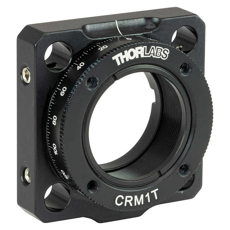
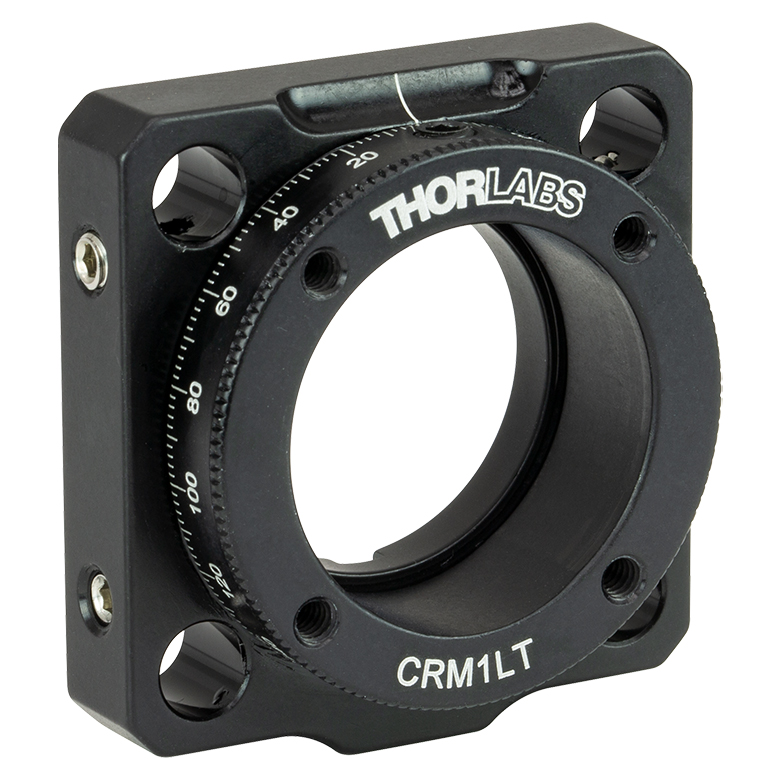
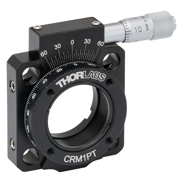
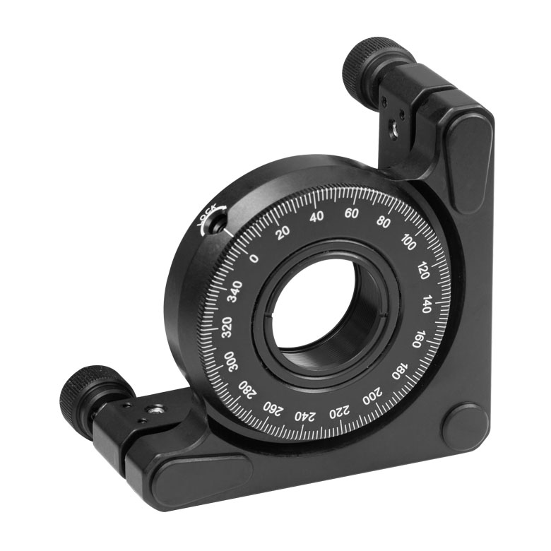
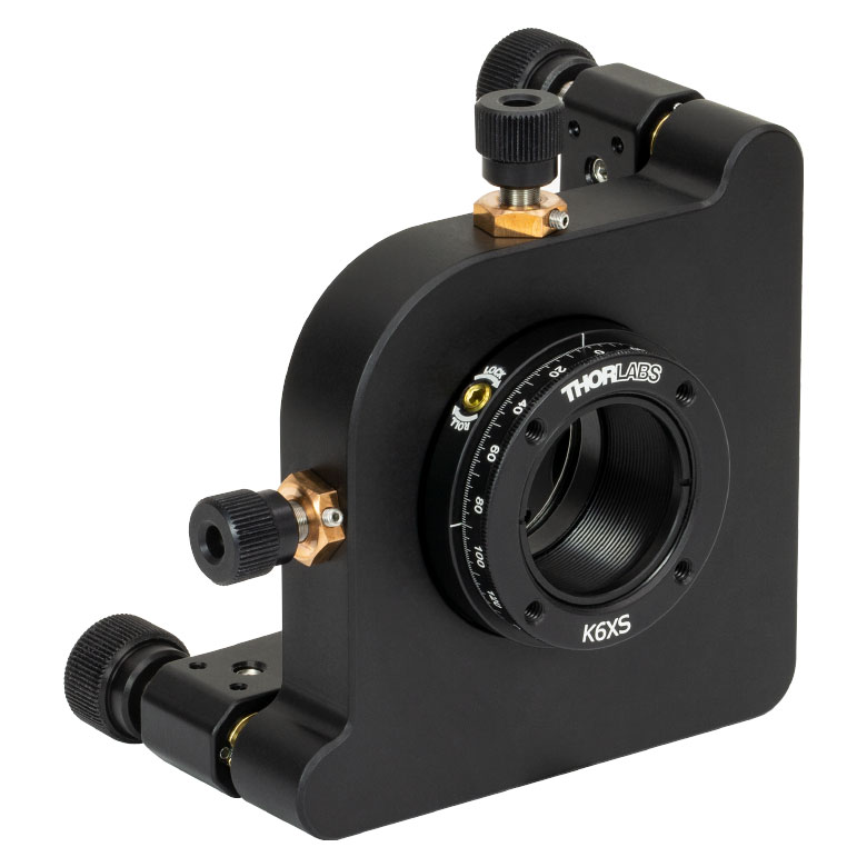
CRM1T(/M) | CRM1LT(/M) | CRM1PT(/M) | KS1RS | K6XS |
| Click Photo to Enlarge |
  |
 |
 |
 |
 |
 |
| Features | Optic Carriage Rotates Within Mounting Ring | 30 mm Cage-Compatiblea | 30 mm Cage-Compatible for Thick Opticsa |
30 mm Cage-Compatible with Micrometera |
±4° Kinematic Tip/Tilt Adjustment Plus Rotation | Six-Axis Kinematic Mounta |
| Additional Details | ||||||
| Rotation Mounts for Ø2" Optics | |||||||
|---|---|---|---|---|---|---|---|
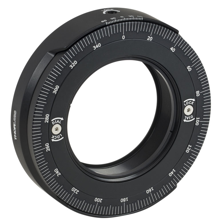
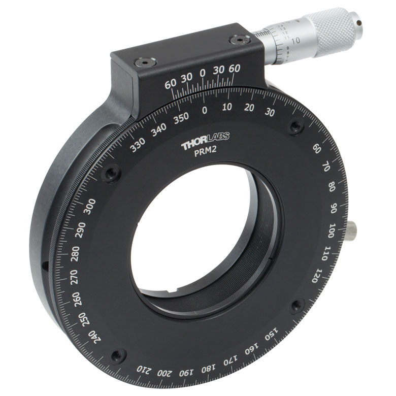
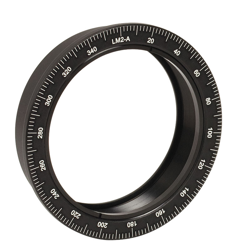
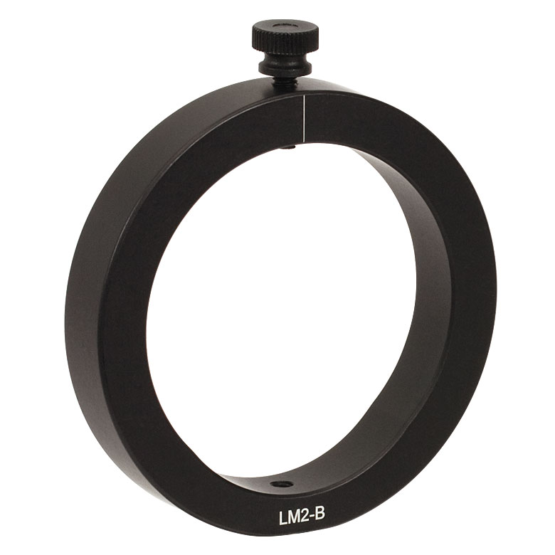
| Item # | RSP2(/M) | RSP2D(/M) | PRM2(/M) | LM2-A & LM2-B(/M) |
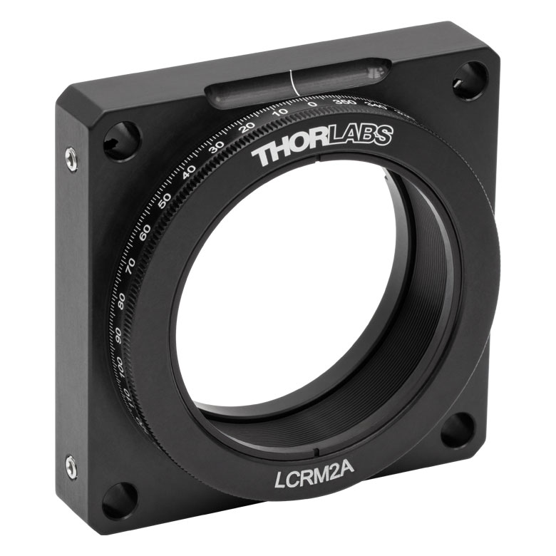
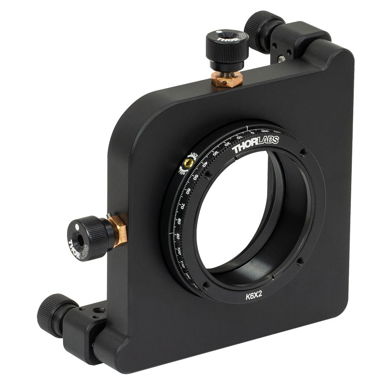
LCRM2A(/M) | KS2RS | K6X2 |
| Click Photo to Enlarge | 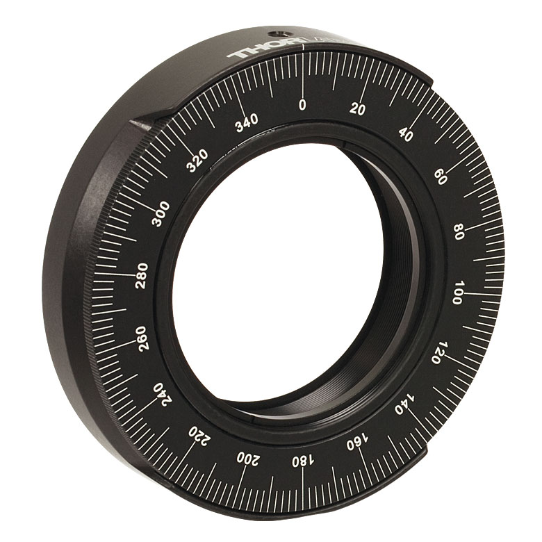 |
 |
 |
  |
 |
 |
 |
| Features | Standard | Adjustable Zero |
Micrometer | Optic Carriage Rotates Within Mounting Ring | 60 mm Cage-Compatible | ±4° Kinematic Tip/Tilt Adjustment Plus Rotation | Six-Axis Kinematic Mount |
| Additional Details | |||||||
Manual Rotation Stages
| Manual Rotation Stages | ||||||
|---|---|---|---|---|---|---|
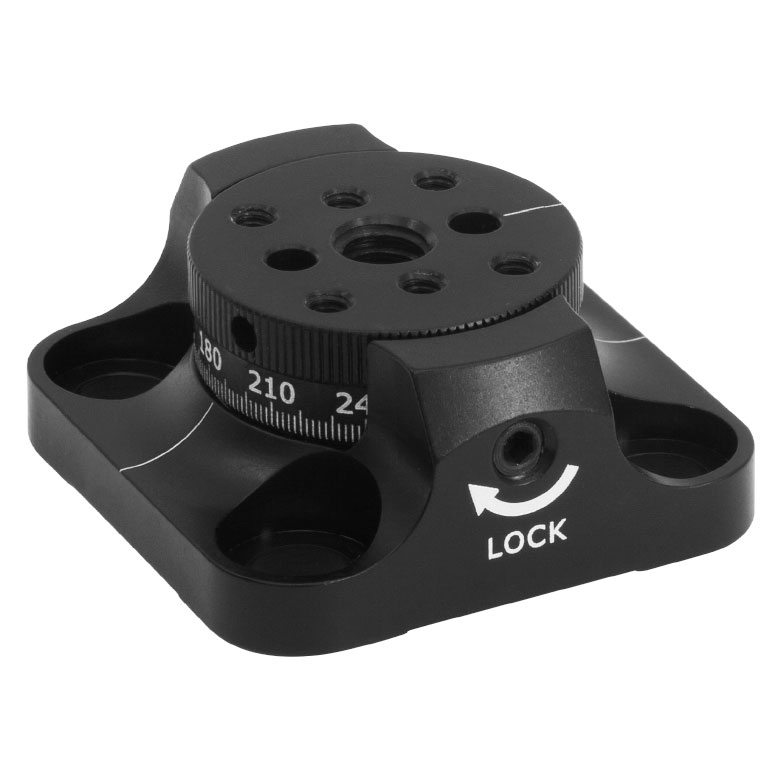
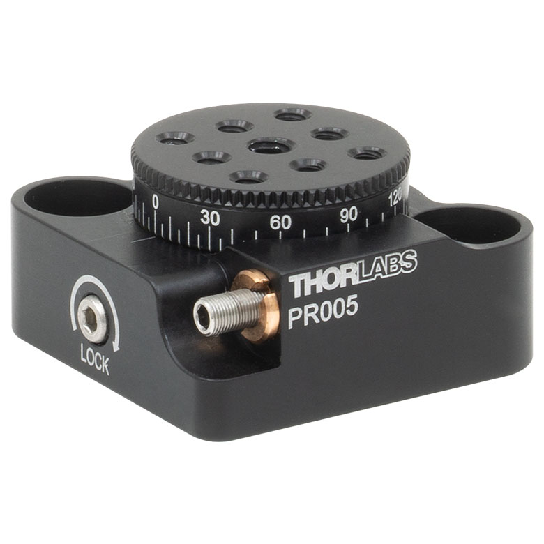
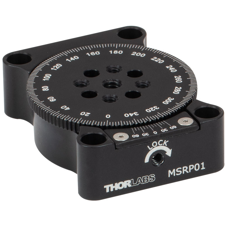
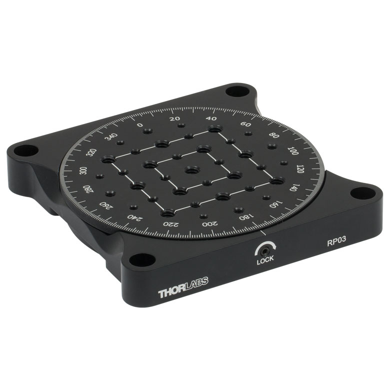
| Item # | RP005(/M) | PR005(/M) | MSRP01(/M) | RP01(/M) | RP03(/M) | QRP02(/M) |
| Click Photo to Enlarge |
 |
 |
 |
 |
 |
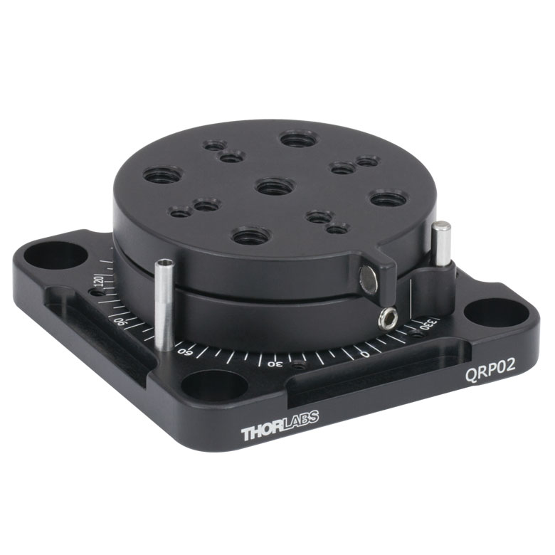 |
| Features | Standard | Two Hard Stops | ||||
| Additional Details | ||||||
| Manual Rotation Stages | ||||||
|---|---|---|---|---|---|---|
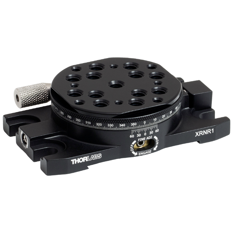
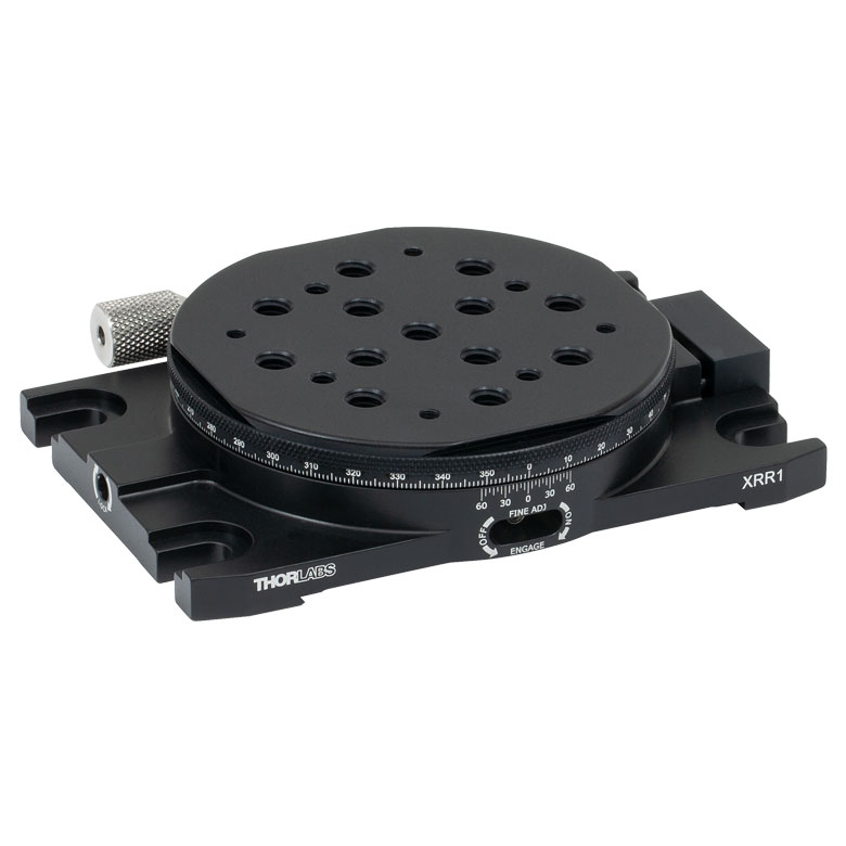
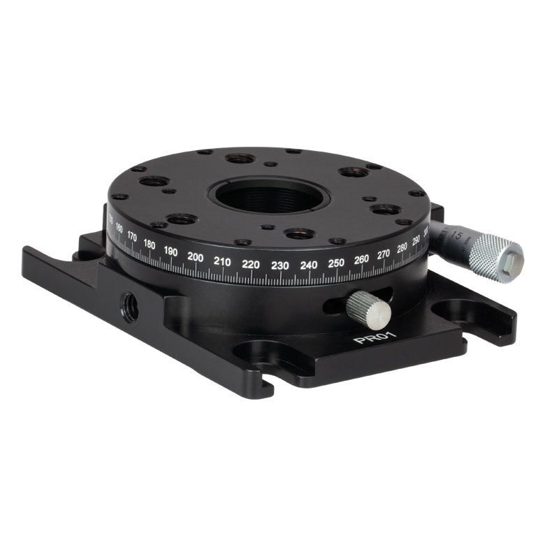
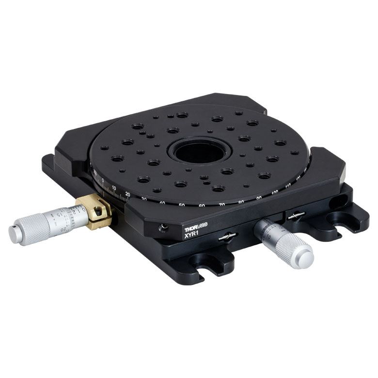
| Item # | XRNR1(/M) | XRR1(/M) | PR01(/M) | CR1(/M) | XYR1(/M) | OCT-XYR1(/M) |
| Click Photo to Enlarge |
 |
 |
 |
 |
 |
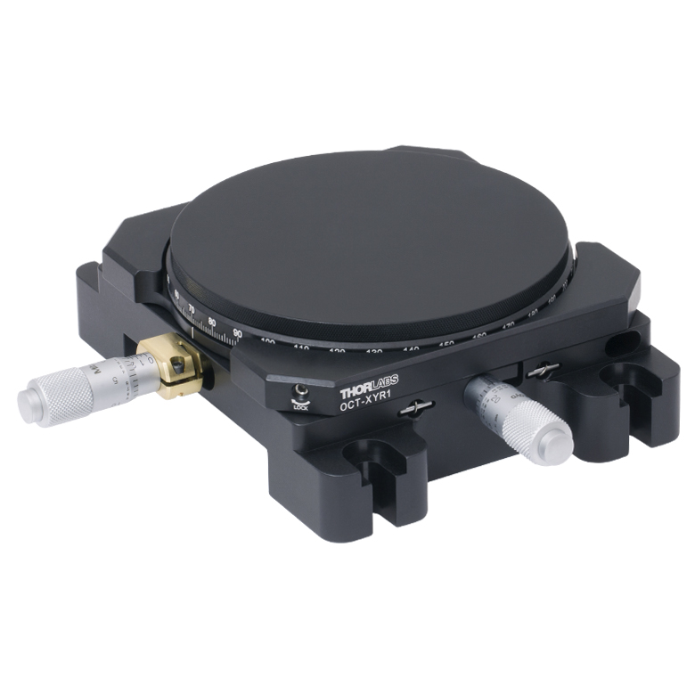 |
| Features | Fine Rotation Adjuster and 2" Wide Dovetail Quick Connect |
Fine Rotation Adjuster and 3" Wide Dovetail Quick Connect |
Fine Rotation Adjuster and SM1-Threaded Central Aperture |
Fine Pitch Worm Gear | Rotation and 1/2" Linear XY Translation | |
| Additional Details | ||||||
Motorized Rotation Mounts and Stages
| Motorized Rotation Mounts and Stages with Central Clear Apertures | |||||
|---|---|---|---|---|---|
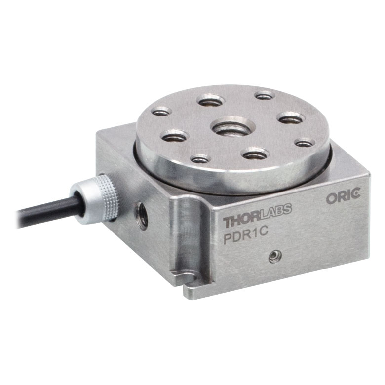
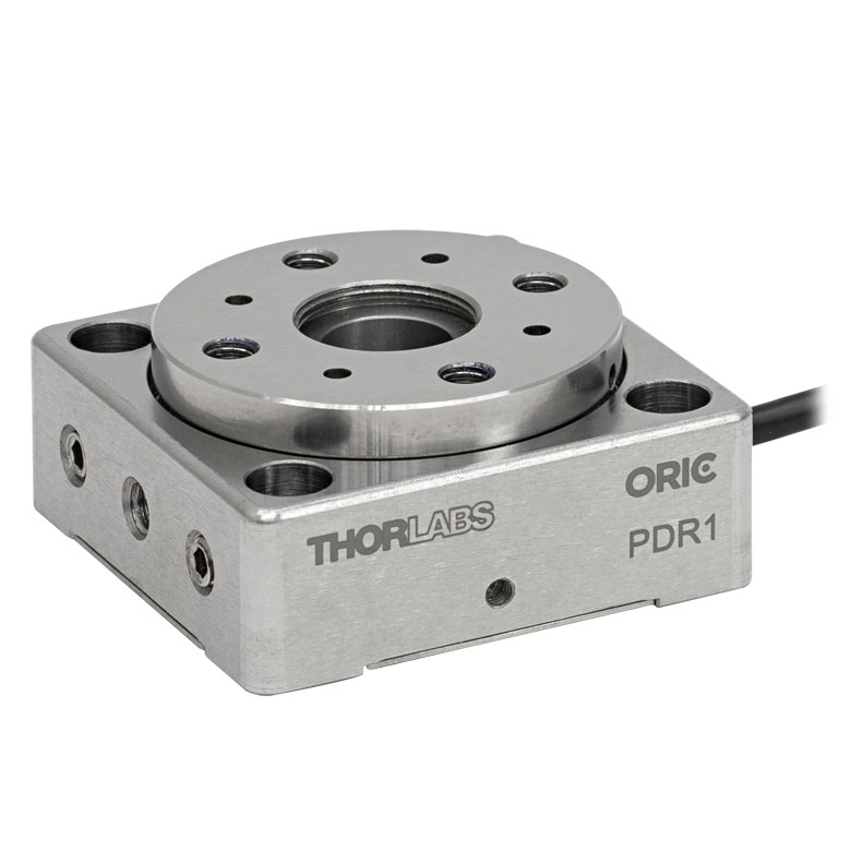
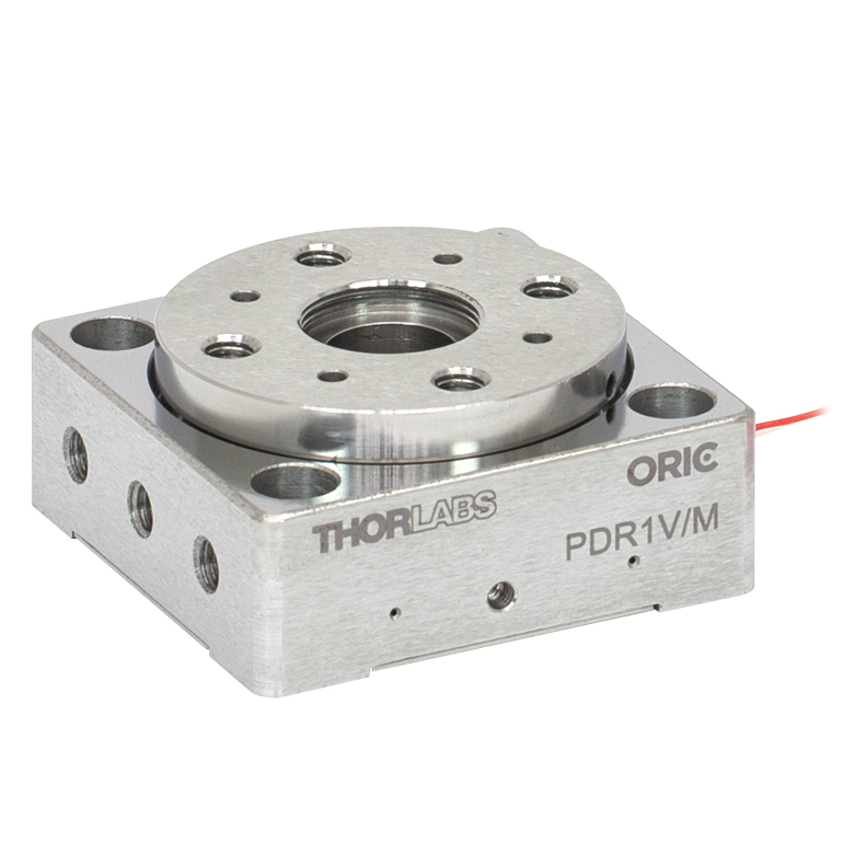
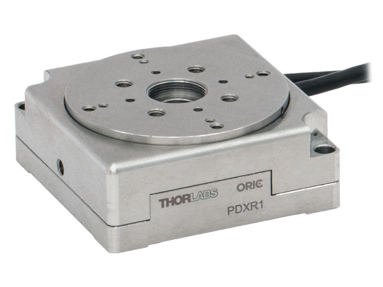
| Item # | DDR25(/M) | PDR1C(/M) | PDR1(/M) | PDR1V(/M) | PDXR1(/M) |
| Click Photo to Enlarge |
 |
 |
 |
 |
 |
| Features | Compatible with SM05 Lens Tubes, 16 mm Cage System, & 30 mm Cage System |
Compatible with 16 mm Cage System |
Compatible with SM05 Lens Tubes & 30 mm Cage System |
Vacuum-Compatible; Also Compatible with SM05 Lens Tubes & 30 mm Cage System |
Compatible with SM05 Lens Tubes & 30 mm Cage System |
| Additional Details | |||||
| Motorized Rotation Mounts and Stages with Central Clear Apertures | |||||||
|---|---|---|---|---|---|---|---|
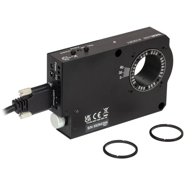
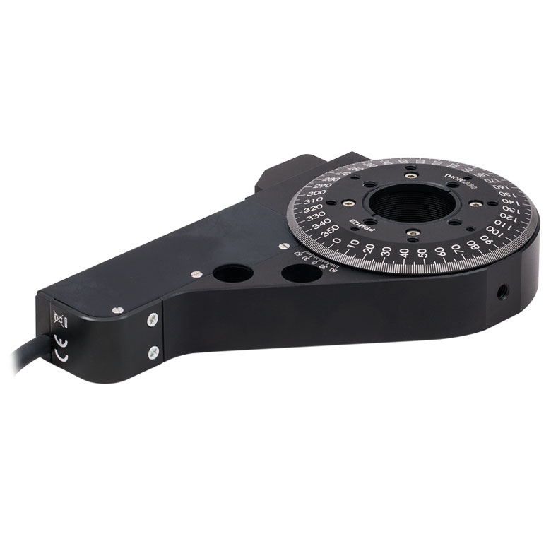
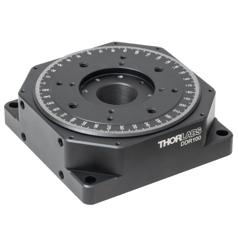
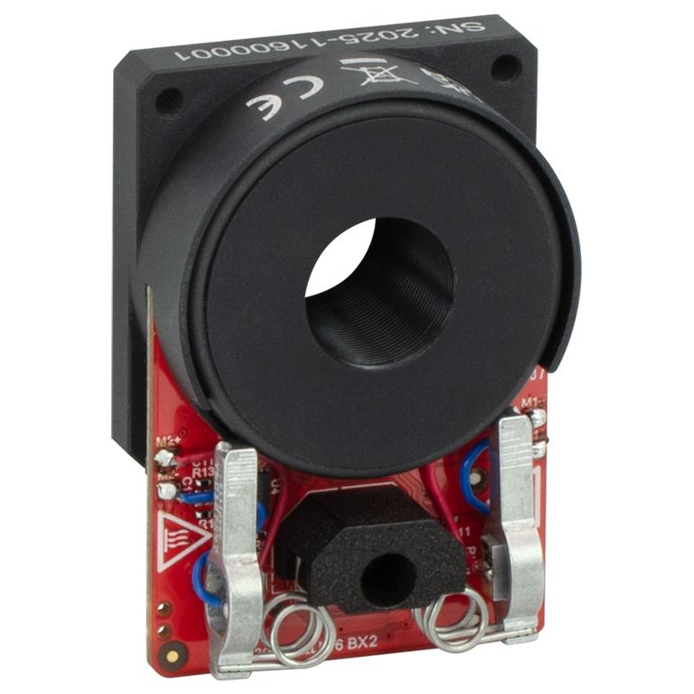
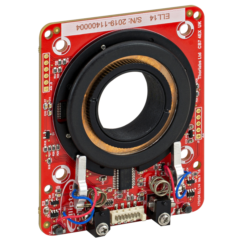
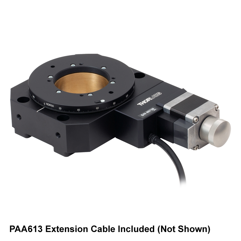
| Item # | K10CR1(/M) | PRM1Z8(/M)a | DDR100(/M) | ELL16 | ELL14 | ELL21(/M) | HDR50(/M) |
| Click Photo to Enlarge |
 |
 |
 |
 |
 |
 |
 |
| Features | Compatible with SM1 Lens Tubes & 30 mm Cage System | Compatible with SM1 Lens Tubes, 16 mm Cage System, 30 mm Cage System |
Compatible with SM05 Lens Tubes, Open Frame Design for OEM Applications |
Compatible with SM1 Lens Tubes, Open Frame Design for OEM Applications |
Compatible with SM2 Lens Tubes, Open Frame Design for OEM Applications |
Compatible with SM2 Lens Tubes |
|
| Additional Details | |||||||
| Motorized Rotation Mounts and Stages with Tapped Platforms | ||
|---|---|---|
| Item # | PRMTZ8(/M)a | ELL18(/M)b |
| Click Photo to Enlarge |
 |
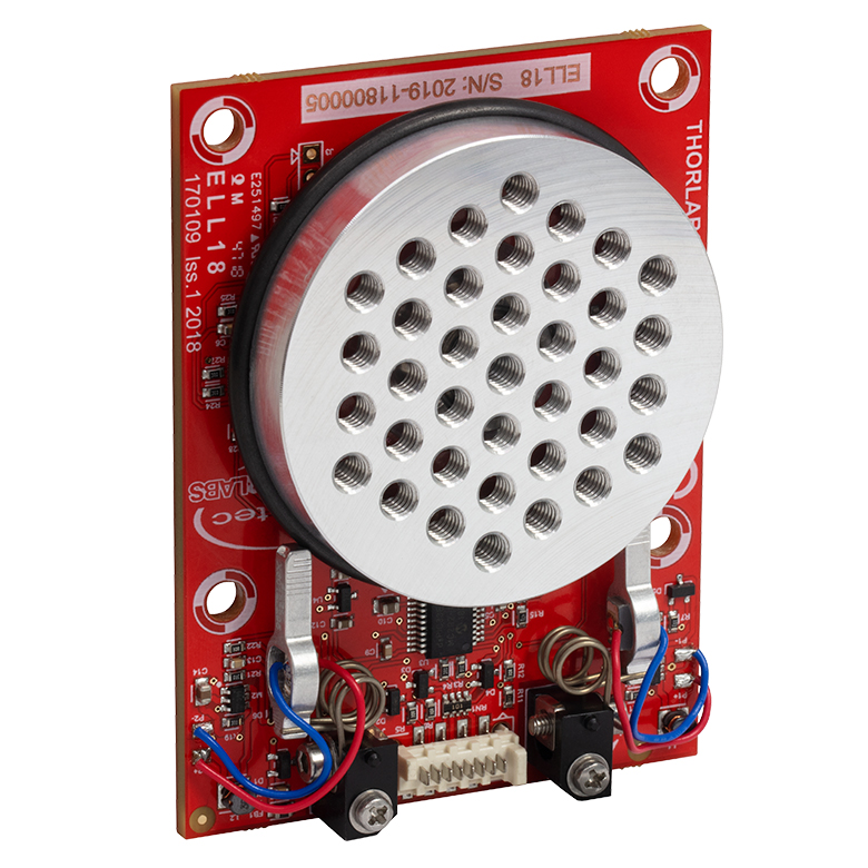 |
| Features | Tapped Mounting Platform for Mounting Prisms or Other Optics | Tapped Mounting Platform, Open Frame Design for OEM Applications |
| Additional Details | ||

 Zoom
Zoom
Click to Enlarge
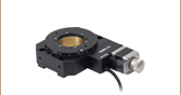
Figure G1.2 PRMTZ8/M Platform Taps
Click to Enlarge
Figure G1.1 PRMTZ8 Platform Taps
The rotating platform features five 1/4"-20 (M6) tapped holes and sixteen 8-32 (M4) holes for general optomechanics, as well as eight 6-32 (M4) holes for compatibility with our PM3 and PM4 prism clamping arms (available below).
The PRMTZ8 is supplied with 16" (0.4 m) of cable. An 8 ft (2.5 m) extension cable (PAA632) is available separately.

 Zoom
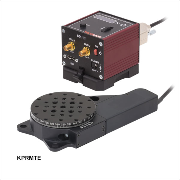
ZoomThe KPRMTE(/M) bundle includes a PRMTZ8(/M) Motorized Rotation Stage with a KDC101 K-Cube® DC Servo Motor Controller. This controller provides smooth, continuous motion that can be automated via the software interface. Each bundle ships complete with a KPS101* power supply and a location-specific adapter.
The KPRMTE(/M) is supplied with 16" (0.4 m) of cable. An 8 ft (2.5 m) extension cable (PAA632) is available separately.
*This previous-generation item is not available for individual purchase. If a replacement is needed, the KPS201 Power Supply can be used.

 Zoom
Zoom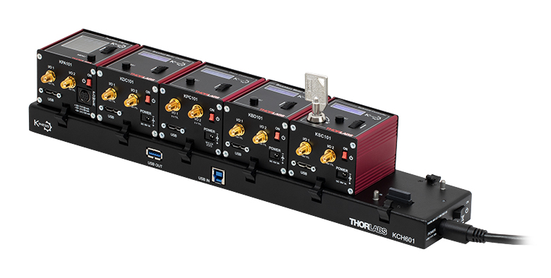 Click to Enlarge
Figure G3.1 KCH601 USB Controller Hub (Sold Separately) with Installed K-Cube® Modules
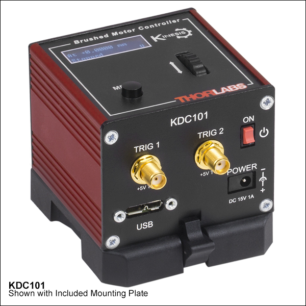
- Front Panel Velocity Wheel and Digital Display for Controlling Motorized Stages or Actuators
- Two Bidirectional Trigger Ports to Read or Control External Equipment
- Interfaces with Computer Using Included USB Cable
- Fully Compatible with Kinesis Software Package
- Compact Footprint: 60.0 mm x 60.0 mm x 49.2 mm (2.42" x 2.42" x 1.94")
- Power Supply Not Included (See Below)
Thorlabs' KDC101 K-Cube® Brushed DC Motor Controller provides local and computerized control of a single motor axis. It features a top-mounted control panel with a velocity wheel that supports four-speed bidirectional control with forward and reverse jogging as well as position presets. A backlit digital display is also included that can have the backlit dimmed or turned off using the top-panel menu options. The front of the unit contains two bidirectional trigger ports that can be used to read a 5 V external logic signal or output a 5 V logic signal to control external equipment. Each port can be independently configured.
The unit is fully compatible with our Kinesis software package. Please note that while the KDC101 controller is also fully supported by our XA software suite, the PRMTZ8(/M) stages are not supported at this time, so the Kinesis software package should be used. A full list of products supported by XA can be found here. Please see the Kinesis Software tab for more information.
Please note that this controller does not ship with a power supply. Compatible power supplies are listed below. Additional information can be found on the main KDC101 DC Servo Motor Controller page.

 Zoom
Zoom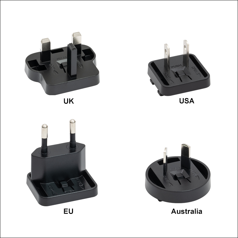
Click for Details
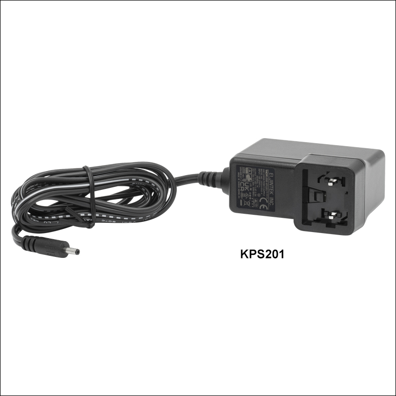
Figure 780B Each KPS201 power supply includes one region-specific adapter, which can be selected upon checkout.
Click to Enlarge
Figure 780A The KPS201 Power Supply Unit
- Individual Power Supply
- KPS201: For K-Cubes® or T-Cubes™ with 3.5 mm Jacks
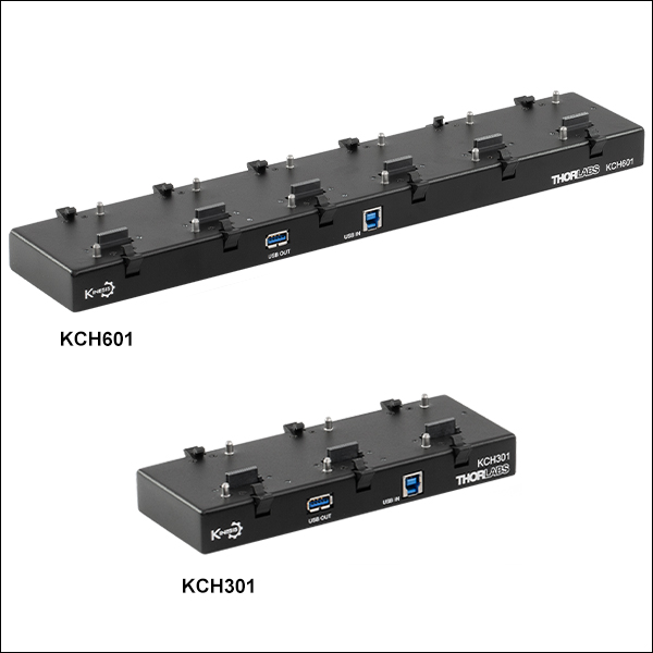
- USB Controller Hubs Provide Power and Communications
- KCH301: For Up to Three K-Cubes or T-Cubes
- KCH601: For Up to Six K-Cubes or T-Cubes
The KPS201 power supply outputs +15 VDC at up to 2.66 A and can power a single K-Cube or T-Cube with a 3.5 mm jack. It plugs into a standard wall outlet.
The KCH301 and KCH601 USB Controller Hubs each consist of two parts: the hub, which can support up to three (KCH301) or six (KCH601) K-Cubes or T-Cubes, and a power supply that plugs into a standard wall outlet. The hub draws a maximum current of 10 A; please verify that the cubes being used do not require a total current of more than 10 A. In addition, the hub provides USB connectivity to any docked K-Cube or T-Cube through a single USB connection.
For more information on the USB Controller Hubs, see the full web presentation.

 Zoom
Zoom
Click for Details
Figure 756A Mechanical Drawings
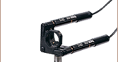
- Provide Clamping Force for Our Platform Mounts
- Threaded Hole on Top and Threaded Stud on Bottom of Post
- 6-32 Threads on PM3 and PM4
- 8-32 Threads on PM5
- M4 x 0.7 Threads on All Metric Versions
- Maximum Optic Heights from 0.97" to 1.65" (24.6 mm to 41.8 mm)
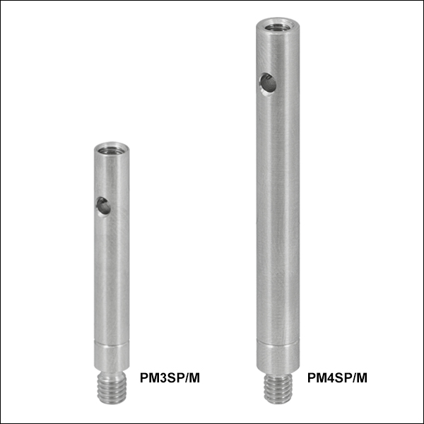
- Extension Posts Available to Increase Max Optic Height
- PM3SP(/M) with PM3(/M): Hold Optics up to 2.21" (56.1 mm) Tall
- PM4SP(/M) with PM4(/M): Hold Optics up to 3.61" (91.7 mm) Tall
Click to Enlarge
Figure 756B Clamping Arm Extension Posts with Metric Indicator Groove
Thorlabs' Clamping Arms provide clamping force to secure optics to our kinematic platform mounts, stages, and V-clamps. The PM3(/M) accommodates optics up to 0.97" tall and features a 0.69" center-to-center distance between the post and the nylon-tipped setscrew that holds the optic. The PM4(/M) accommodates optics up to 1.61" and features a 1.16" center-to-center distance between the post and the nylon-tipped setscrew. The maximum optic height of the PM3(/M) or PM4(/M) Clamping Arms can be extended using our PM3SP(/M) or PM4SP(/M) Extension Posts, respectively. These extension posts are identical to the posts included in each complete clamping arm. Each clamping arm features 6-32 (M4 x 0.7) threads. The PM3 and PM4 can be mounted in 8-32 tapped holes by using the AS6E8E thread adapter, which features internal 6-32 threads and external 8-32 threads. This thread adapter has an outer diameter of 0.24", which is the same as the PM4SP extension post and the post included with the PM4 clamping arm. This allows the clamping arm to be adjusted across the seam between either post and the adapter. The smaller diameters of the included post for the PM3 clamping arm and the PM3SP extension post cause the thread adapter to act as a stop for the clamping arm.
The PM5(/M) clamping arm is made entirely from heat-treated stainless steel, which helps maintain stability in fluctuating temperatures and provides vacuum compatibility. This clamping arm is recommended for use with the POLARIS-K1M4(/M), but it can be used with any platform mount or stage that has one or more 8-32 (M4 x 0.7) tapped holes. The PM5(/M) can hold optics up to 1.65" tall, and the distance from the post center to the contact point that holds the optic is 0.90".
Each clamping arm is attached to its post using a flexure mechanism that locks with a 5/64" (2.0 mm) balldriver or hex key. The setscrew on top of the clamping arm also accepts a 5/64" (2.0 mm) balldriver or hex key in order to clamp down on the optic. The post includes a through hole which can be leveraged for added torque when tightening down the post. Please see Figure 756A for additional information.