 Products Home / Fiber Components / Collimation / Coupling / Aspheric Fiber Collimators, Pigtailed SM Fiber
Aspheric Fiber Collimators, Pigtailed SM Fiber
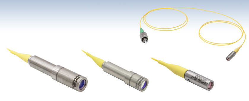
- 1 m SM Fiber Pigtail with FC/PC or FC/APC Connector
- Eight Alignment Wavelengths from 532 to 1550 nm
- Custom Alignment Wavelengths Available
CFS18-1030-FC
1030 nm, FC/PC Collimator
Focal Length: 18.56 mm
CFS11-633F
633 nm, FC/PC Collimator
Focal Length: 10.96 mm
CFS5-1310-APC
1310 nm, FC/APC Collimator
Focal Length: 4.70 mm
CFS5-1310-APC
1310 nm, FC/APC Collimator
Focal Length: 4.70 mm


Please Wait
| Quick Links to Available Wavelengths |
|---|
| 532 nm |
| 633 nm |
| 780 nm |
| 850 nm |
| 1030 nm |
| 1064 nm |
| 1310 nm |
| 1550 nm |
Features
- Compact Fiber Collimation Packages
- SM Fiber Pigtail with FC/PC or FC/APC Connectors Available
- Custom Wavelength and Connectors Available by Contacting Tech Support
- Non-Magnetic Stainless Steel Housing
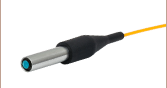
The CFS series of pigtailed fiber collimators is a compact solution for OEM applications. The collimation package consists of a stainless steel housing and an aspheric lens. Each unit uses 1 m of single mode fiber pigtailed to the collimation package so that the performance of the collimator is diffraction limited at the design wavelength.
The fiber end pigtailed to the collimation package is angle-polished and AR-coated to minimize reflections at the design wavelength. To accommodate the angle polish, the CFS11 and CFS18 collimators have an angled housing. The deflection caused by the angled output over the extremely short focal lengths of the CFS2 and CFS5 collimators is negligible, allowing these versions to have straight housings. The other end of the fiber has an FC/PC, narrow key connector for the 532 nm, 633 nm, 780 nm, 1030 nm, and 1064 nm wavelength packages and an FC/APC, narrow key connector for the 850 nm, 1310 nm, and 1550 nm wavelength packages. These collimation packages can be easily customized for any wavelength in the visible and near IR spectral regions. In addition, the fiber connector, fiber type, and fiber length can all be customized; please contact Tech Support for a quote.
| θ | Divergence Angle |
| D | Mode-Field Diameter (MFD) |
| f | Focal Length of Collimator |
The divergence angle (in degrees) ,
,
where D and f must be in the same units.
Divergence Angle Comparison
The divergence angle can be estimated using formula (1), given that the light emerging from the fiber has a Gaussian intensity profile. This formula works well for single mode fibers, like those found on these pigtailed collimators, but will underestimate the divergence angle for multimode fibers where the light emerging from the fiber has a non-Gaussian intensity profile.
Simulations of the theoretical divergence when using one of our standard collimators at wavelengths other than the design wavelength are shown in Figures 2.1 through 2.4. For example, if you need to collimate 700 nm light from a fiber into a ~1.5 mm diameter beam, the CFS5-780F collimator (represented by the '-780' line in Figure 2.2) can be used but will provide a higher divergence than at its design wavelength of 780 nm. Individual theoretical divergence plots are also available below for each collimator. Please contact Tech Support to request a collimator aligned at a
custom wavelength.
Click to Enlarge
Figure 2.1 Graph of CFS2 Collimator Divergence
Click to Enlarge
Figure 2.2 Graph of CFS5 Collimator Divergence
Click to Enlarge
Figure 2.4 Graph of CFS18 Collimator Divergence
Click to Enlarge
Figure 2.3 Graph of CFS11 Collimator Divergence
| d | Beam Diameter |
| λ | Wavelength |
| f | Focal Length of Collimator |
| MFD | Mode-Field Diameter |
The beam diameter (in millimeters) ,
,
where λ and MFD must be in the same units.
Theoretical Approximation of the Divergence Angle
The 1/e2 beam diameter as a function of propagation distance was simulated for each of our collimators at the design wavelength, assuming input from the design fiber and a Gaussian intensity profile. Formula (1) is an approximation for these beam diameters. This works well for single mode fibers, like those found on these pigtailed collimators, but will underestimate the beam diameter for multimode fibers where the light emerging from the fiber has a non-Gaussian intensity profile.


Theoretical Approximation of the Divergence Angle
The full-angle beam divergence listed in the specifications tables is the theoretically-calculated value associated with the fiber collimator. This divergence angle is easy to approximate theoretically using Formula (1) as long as the light emerging from the fiber has a Gaussian intensity profile. Consequently, the formula works well for single mode fibers, but it will underestimate the divergence angle for multimode (MM) fibers since the light emerging from a multimode fiber has a non-Gaussian intensity profile.
The Full Divergence Angle (in degrees) is given by

where MFD is the mode field diameter and f is the focal length of the collimator. (Note: MFD and f must have the same units in this equation).
Example:
When the F220FC-A collimator (f ≈ 11.0 mm; not exact since the design wavelength is 543 nm) is used to collimate 515 nm light emerging from a 460HP fiber (MFD = 3.5 µm), the divergence angle is approximately given by
θ ≈ (0.0035 mm / 11.0 mm) x (180 / pi) = 0.018°.
When the beam divergence angle was measured for the F220FC-A collimator, a 460HP fiber was used with 543 nm light. The result was a divergence angle of 0.018°.
Theoretical Approximation of the Output Beam Diameter
The output beam diameter can be approximated from

where λ is the wavelength of light being used, MFD is the mode field diameter, and f is the focal length of the collimator. (Note: MFD and f must have the same units in this equation).
Example:
When the F240FC-1550 collimator (f = 8.18 mm) is used with the P1-SMF28E-FC-1 patch cable (MFD = 10.4 µm) and 1550 nm light, the output beam diameter is
d ≈ (4)(0.00155 mm)[8.18 mm / (pi · 0.0104 mm)] = 1.55 mm.
Theoretical Approximation of the Maximum Waist Distance
The maximum waist distance, which is the furthest distance from the lens the waist can be located in order to maintain collimation, may be approximated by
where f is the focal length of the collimator, λ is the wavelength of light used, and MFD is the mode field diameter. (Note: MFD and f must have the same units in this equation).
Example:
When the F220FC-532 collimator (f = 10.9 mm) is used with the P1-460B-FC-1 patch cable (MFD ≈ 4.0 µm; calculated approximate value) and 532 nm light, then the maximum waist distance is approximately
zmax ≈ 10.9 mm + [2 · (10.9 mm)2 · 0.000532 mm] / [pi · (0.004 mm)2] = 2526 mm.

Insights into Best Lab Practices
Scroll down to read about a practice we follow when setting up lab equipment.
- Align Fiber Collimators to Create Free Space Between Fibers
Click here for more insights into lab practices and equipment.
Align Fiber Collimators to Create Free Space Between Fibers
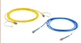
Two collimators, inserted into a fiber optic setup, provide free-space access to the beam. The first collimator accepts the highly diverging light from the first fiber and outputs a free-space beam, which propagates with an approximately constant diameter to the second collimator. The second collimator accepts the free-space beam and couples that light into the second fiber. Some collimation packages, including the pair used in this demonstration, are designed for use with optical fibers and mate directly to fiber connectors.
Ideally, 100% of the light emitted by the first fiber would be coupled into the second fiber, but some light will always be lost due to reflections, scattering, absorption, and misalignment. Misalignment, typically the largest source of loss, can be minimized using the alignment and stabilization techniques described in Video 179A.
In this demonstration, the first fiber is single mode. The optical power incident on the second collimator, as well as the power output by the second fiber, are measured. When the second fiber is multimode with a 50 µm diameter core, alignment resulted in 91% of the power incident on the second collimator being measured at the fiber output. This value was 86% when the second fiber is single mode. Some differences in collimator designs, and their effects on the characteristics of the collimated beams, are also discussed.
If you would like more information about tips, tricks, and other methods we often use in the lab, we recommend our other Video Insights. In addition, our webinars provide practical and theoretical introductions to our different products.
| Products Featured During Demonstration | ||||
|---|---|---|---|---|
| Fiber-Coupled Laser | Kinematic Mounts | Fiber Adapter Cap (for Power Sensor) |
Single Mode Patch Cable (FC/PC) | Fiber Cable Storage Reels |
| Triplet Fiber Optic Collimators | Power Sensor | Power Meter | Hybrid Single Mode Patch Cable | 2" Posts |
| Adapter (Mount-to-Collimator) |
SM1 Thread Adapter (for Power Sensor) |
Fiber Connector Cleaner | Step-Index Multimode Patch Cable | Ø1/2" Post Holders |
Date of Last Edit: April 21, 2021
| Posted Comments: | |
cdolbashian
(posted 2025-01-10 12:37:32.0) Thank you for reaching out to us with this inquiry. While some of the -C coatings appear differently in the graphs we provide, the important takeaway is that we guarantee R_average<0.5% over the specified wavelength range at 0°AOI. Solomiya Lebid
(posted 2024-11-07 09:35:19.017) Hi,
I am looking for a single mode pigtailed aspheric collimator aligned at the 488 nm wavelength. Also, I would like to know the collimated output beam characteristics (M squared, pointing stability, etc.). Please, let me know if you can make one like that.
Best
Solomiya blarowe
(posted 2024-11-07 03:02:10.0) Thank you for contacting Thorlabs. I've reached out to you directly to discuss this. user
(posted 2024-03-18 14:15:06.957) Hello, could you please provide the pointing accuracy specification for the CFS11-1310-APC? I've noticed that similar products from other companies offer a pointing accuracy of 1 degree, but I've been unable to find this specific detail for Thorlabs' product. jdelia
(posted 2024-04-02 11:09:19.0) Thank you for contacting Thorlabs. While we do not have an official specification to offer, the accuracy should be <1.9°, with a typical value of 1.2°. YANGXIN CAO
(posted 2024-01-17 11:41:23.53) 请问这个产品的IL是多大?
我的光源的模斑半径是3um,发散角是+/-16°(半锥角是16°),波长是1310nm。 ksosnowski
(posted 2024-01-17 12:19:59.0) Thanks for reaching out to Thorlabs. For our Aspheric Collimators, while we are able to directly measure the insertion loss on the freespace output during assembly with a fiber coupled laser input, we unfortunately cannot specify the loss for launching light into the collimator side as this can vary with the input beam parameters and alignment. The output specs for the collimators can be referenced to match similar parameters on an input beam to achieve good performance. I have reached out directly to discuss your application in further detail. SONY UDAYAN
(posted 2023-05-16 10:20:15.833) will this collimator can be used with femtosecond laser with a max power of 20 mW. jdelia
(posted 2023-05-17 10:58:20.0) Thank you for contacting Thorlabs. I have contacted you directly to clarify the specifications of your beam to determine whether it may be suitable for use with the CFS18-850-APC. Faisal R Ahmad
(posted 2023-05-10 10:57:35.89) Hi,
My name is Faisal and I have been a Thorlabs customer for over twenty years. I have a quick question: Is there any chance that you can provide this component with an APC connector? I am building a test setup which requires sixteen of these collimators and having an APC connector would be very beneficial. If you have any questions please do not hesitate to contact me.
With kind regards,
-faisal
Faisal R Ahmad
Head of Systems Engineering, Detect Inc.
ph. 607-351-0240 ksosnowski
(posted 2023-05-11 12:07:09.0) Hello Faisal and thanks for reaching out to Thorlabs. We are able to offer other connectors from our catalogue like APC on these collimator pigtails as a custom item. I have reached out directly to discuss this further. Kent Talbert
(posted 2022-11-04 15:48:50.113) Is it possible to get the 1064 nm SM Pigtailed Aspheric Collimators with a FC/APC connector instead of the FC/PC? cdolbashian
(posted 2022-11-08 02:14:53.0) Thank you for reaching out to us with this inquiry. This is indeed possible, and I have reached out to you with details. For future custom requests, please feel free to email techsales@thorlabs.com Gabriele Biagi
(posted 2022-04-12 07:57:32.653) Dear Thorlabs,
is It possible to find the details of a Thorlabs's collimators from the serial number? The serial numbers are SN 230196-04 and SN 83453-1
Best Regards,
Gabriele Biagi jdelia
(posted 2022-04-22 08:23:50.0) Thank you for contacting Thorlabs. These collimators are not serialized. I have reached out to you directly to look further into which collimator you may have. jie chen
(posted 2022-01-06 11:46:56.11) 您好!
请问CFS5-1064-FC中尾纤是否有型号或者链接呢?也就是说,我不需要前面的准直镜,只需要后面的尾纤。 user
(posted 2020-06-17 19:00:11.83) Can you tell me what are the power handling/damage thresholds are for your various collimators? We are interested in an application with up to 2W CW in the visible spectrum and are wondering if any of these options would be viable for this. Thanks! nbayconich
(posted 2020-06-18 09:58:50.0) Thank you for your feedback, most of lenses used in our collimation packages should be fine using a 2 watt visible CW source, however we would be more concerned about damaging the fiber or fiber connectors. We recommend to not exceed 300mW of power for our fiber connectors when coupling light into fiber.
Please see our fiber damage threshold tab below for more information.
https://www.thorlabs.com/newgrouppage9.cfm?objectgroup_id=1362&tabname=damage%20threshold
I will reach out to you directly to discuss your application. Salah Awel
(posted 2020-02-27 18:05:24.27) Can I use CFS18-532-FC collimator to inject laser into single mode fiber?
Regards,
Dr. Salah llamb
(posted 2020-03-03 03:57:27.0) Hello Dr. Salah, thank you for contacting Thorlabs. These aspheric collimators can indeed be used for coupling light into the pigtailed fiber as well, though only recommended for use at the design wavelength. I have reached out to you directly to discuss your application further. user
(posted 2019-06-18 15:03:35.353) Please help to provide the tolerance of 9.02mm outer diameter. I need to design a component to match the collimator. Thank you. YLohia
(posted 2019-06-18 09:22:58.0) Hello, thank you for contacting Thorlabs. The tolerance for the outer cell of the CFS11-1550-APC is 0.355" +/- 0.002". user
(posted 2019-04-10 11:45:52.35) Hi,in the beam diameter plots page,the formula need MFD to calculator beam diameter.If I don't MFD of my fiber,how could I get the beam diameter? Can I use the formula in Collimation Tutorial.thorlabs with fiber NA of my fiber?Which formula is more correct?
thanks. nbayconich
(posted 2019-04-11 09:29:55.0) Thank you for contacting Thorlabs. The equation under the beam diameter plots section can be used to calculate the collimated gaussian beam diameter produce by the fiber type you have with the chosen collimator of focal length f. There are several other equations you can use to predict the beam diameter, the other equation you may be referring to under the collimation tutorial section in the link below calculates the FWHM diameter of your collimated beam using the divergence angle of the laser diode source. Either formula is correct and you can convert the FWHM to the 1/e^2 value by multiplying your FWHM beam by about 1.7X. If you do not know the MFD of your fiber type then you can simply use a similar equation to the one found in the "collimation tutorial" to estimate the collimated full beam diameter of your fiber source and collimator using Ø=2*f*NA.
https://www.thorlabs.com/tutorials.cfm?tabID=f7ed0dd5-3f31-4f84-9843-e0f7ac33f413 sebastien.sauvage
(posted 2016-05-24 18:47:31.017) What does EFL mean ? besembeson
(posted 2016-05-25 01:57:05.0) Response from Bweh at Thorlabs USA: This is the Effective Focal Length, which for a thick lens is the distance between the front or back principal plane to the focus point. info
(posted 2015-07-21 01:34:16.633) Please let me know if collimators for 1064nm and 532nm are available with polarization maintaining fiber
Krishna besembeson
(posted 2015-09-23 02:42:10.0) Response from Bweh at Thorlabs USA: This is possible. I will follow-up with you. svtoma
(posted 2015-04-08 13:12:26.417) I need a collimator to reflect 50% of intensity back and 50% to transmit, but transmitted scattered light to be catched with the same collimator and send back together with early reflected wave. Almost similar to Fabry Perot Interferometer. jlow
(posted 2015-06-05 09:59:10.0) Response from Jeremy at Thorlabs: We can think of several ways to implement this based on the requirements of your application. We will contact you directly to discuss more about this. jhhe
(posted 2014-07-18 03:32:10.777) what is the damage threshold of CFS11-1064-FC, for CW and pulsed case? jlow
(posted 2014-08-07 02:18:57.0) Response from Jeremy at Thorlabs: The damage threshold depends on factors such as coupling efficiency, presence of dirt/dust on optical surface, etc. We recommend keeping the average power to be <300mW to avoid damaging the fiber. You can go higher if you have good coupling efficiency. Also, if there's dust/dirt on either the lens or the fiber surface, then it can get damaged even with very low power. C.Farrell
(posted 2014-05-26 14:46:16.6) Hi, Out of interest can you supply the CFS18-1064 collimator using PM980 fibre and for similar cost? Thanks. pbui
(posted 2014-06-02 11:45:07.0) We should be able to offer this custom pigtailed collimator. We will contact you to get your exact requirements and to provide a quote. user
(posted 2013-10-18 17:41:25.717) Would you give us a hint to mount CFS5-1030-FC on your kinematic mirror mount? cdaly
(posted 2013-10-21 13:15:00.0) Response from Chris at Thorlabs: Thank you for your feedback. The pigtailed aspheric collimators can be mounted directly into the Kinematic V-Clamp Mount KM100V, found here: http://www.thorlabs.com/newgrouppage9.cfm?objectgroup_id=1321&pn=KM100V#1321 tcohen
(posted 2012-08-21 16:18:00.0) Response from Tim at Thorlabs: The lower limit is typically 450nm due to the limitations of the housing. Also, as you mentioned we would need to use alternative optics as the standard lenses we use have very limited transmission at 200nm that would prevent this from being useful. Furthermore, the cutoff for our lowest operating wavelength silica core SMF (SM300) is approximately 310nm. I will contact you to discuss the requirements of the fiber and collimator. Perhaps a UV-Enhanced Aluminum reflective collimator such as the RC08FC-F01 would be better able to meet your requirements. jlowder
(posted 2012-08-21 10:34:51.0) Hello, I was wondering if you can get any of these with fused silica optics or something similar for wavelengths between 200nm-400nm. Thanks. tcohen
(posted 2012-05-11 16:17:00.0) Update from Tim at Thorlabs to clarify an unclear previous post: I would like to mention that the max waist distance calculated was the theoretical limit that the beam waist could be placed based on the fiber and collimation optic. When manufacturing these, we look to minimize divergence and because small changes in the distance between the fiber and the optic will cause significant changes in the waist distance, the beam waist distance may vary. tcohen
(posted 2012-05-04 16:53:00.0) Response from Tim at Thorlabs: Thank you for your feedback. The coupling efficiency will depend on alignment. Lateral offset, separation and tilt will all play a role. I see you have posted on a couple feedback and mentioned your source is also variable. Chromatic focal length shift will also decrease the coupling efficiency. We do have adjustable fiber collimators to compensate for this shift as well as FiberPorts which offer linear and angular movement. I will contact you to discuss the options that may suit your application. scottie730318
(posted 2012-05-04 11:34:37.0) Hi, If I buy the two Pigtailed Aspheric Fiber Collimators (CFS5-1064-FC). One of the Fiber Collimators is collimating the beam out of Hi-1060 fiber, and focusing the collimation beam into the another Fiber collimator. What distance is the distance to the highest coupling efficiency? What valve is the coupling efficiency?
Thanks tcohen
(posted 2012-04-11 11:28:00.0) Response from Tim at Thorlabs: There will be a few things to consider. First, it is important to know that imperfect coupling and contaminants can both lower the damage threshold. Next, the energy density must be considered for both the coated lens and the focused spot in the fiber. To calculate this, we would need your beam diameter and intensity profile. If you are coupling into this fiber, it is also important to remember that these are pre-aligned for the design wavelength. A deviation in wavelength will cause a focal length shift and therefore may focus the spot inappropriately on the fiber where it can be damaged more easily. Also, because of your ultrashort pulse, damage may occur by avalanche ionization, which has different thresholds than normal pulsed and CW LIDT. I have contacted you to further discuss the suitability of this product in your setup. scottie730318
(posted 2012-04-07 10:51:39.0) Hi, what would the maximum power rating be for CFS5-1064-FC, and CFS11-1064-FC.
Average power of our laser is about 50mW, repetition rate is 30MHz, pulse with is about 300fs
Are the CFS5-1064-FC and CFS11-1064-FC suitable to our laser system. Or would you recommend these or another lens for close work in our laser. Thanks, Hou-Ren Chen tcohen
(posted 2012-03-29 14:53:00.0) Response from Tim at Thorlabs: The maximum waist distance can be approximated by zmax = f + 2*lambda*f^2 / pi*MFD^2. For the CFS5-1064-FC with about 1060 nm, that would be 4.6 mm + 2(1060nm)(4.6mm)^2 / pi*(6.2um)^2 or about 376mm. scottie730318
(posted 2012-03-20 01:02:43.0) What distance is the max waist distance (CFS5-1064-FC) with about 1060 nm ? bdada
(posted 2012-02-07 14:22:00.0) Response from Buki at Thorlabs:
Thank you for participating in our feedback forum. As a guideline, the anti-reflective coatings on our aspheric lenses can withstand 100 W/cm2 CW input power or 0.1 J/cm2 with 10 ns pulses energy at 1064 nm.
However, within the collimation packages, we have found that a damage threshold of 25W/cm^2 is advisable. Please contact TechSupport@thorlabs.com if you have additional questions. rumbaulk
(posted 2012-02-04 23:17:39.0) Hi, what would the maximum power rating be for these lenses? Would you recommend these or another lens for close work in and out of fibers with up to 30W signals?
Thanks,
Luke Rumbaugh bdada
(posted 2011-08-22 16:01:00.0) Response from Buki at Thorlabs:
The aspheric lens in the particular collimator you are looking at, the CFS18-532-FC, is the 352280-A. The NA is 0.15 and the RMS wave front error is diffraction limited, so this should be sufficient for your application. Please contact TechSupport@thorlabs.com if you have further questions. ziqiangliu
(posted 2011-08-21 22:08:33.0) Dear Sir/Madam,
We need several aspheric fiber colllimator in 532nm. We need use the collimator at 300m distance. I need the NA is 0.15, MFD 3.5um, waist dia. less than 20mm,divengence less than 0.2mrad. It looks the CFS18-532-FC suit for our application. But mostly we concerned is the wave phase differencial should be less than 1/4 lambada. The colliatomator we used now have a clear diffraction ring at 300m distance. Is the CFS18-532-FC suit for our application? Or you have another better recommendation?
Best regards,
Jeffery Liu jjurado
(posted 2011-02-28 13:57:00.0) Response from Javier at Thorlabs to lpnirpol: Thank you for contacting us with your inquiry. Although we have not tested these fiber couplers in a fiberbench configuration like the FFBM-S-1550-Y, we expect the insertion loss to be very close to that of this fiber bench coupler when both collimators are used in a similar configuration. So you can expect an insertion loss of 0.6 dB (+/- 0.3 dB). lpnirpol
(posted 2011-02-25 16:47:40.0) Can you give the minimum expected insertion loss for when pairing these collimators like in the Permanent Pigtailed Fiber-Fiber Coupler product (FFBM-S-1550-Y). Greg
(posted 2010-04-14 10:55:29.0) A response from Greg at Thorlabs to logly1019: I have added links to our small V-Clamps in the tables above each price box. These clamps are well suited to mount these pigtailed collimators. The adapter Adam mentioned will also work for the CFS18 models. I will have our engineering team look at adding additional SM1 style adapters for our other pigtailed collimators. Adam
(posted 2010-04-14 08:49:29.0) A response from Adam at Thorlabs to logly1019: The CFS18-850-APC can be mounted in SM1 threads using a AD9.5F. logly1019
(posted 2010-04-13 22:33:10.0) What kind adapter can use for CFS18-850-APC? thanks. apalmentieri
(posted 2009-02-24 11:09:29.0) On this page there are no accessories or related items linked. Under related items, it may be a good idea to link fiberports, adjustable collimators, and fixed collimators. Under accessories, it may be a good idea to link fiber coupled laser sources, pigtailed laser diodes, and mating sleeves. |
Fiber Collimator Selection Guide
Click on the collimator type or photo to view more information about each type of collimator.
| Type | Description | |
|---|---|---|
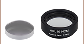
| Fixed FC, APC, or SMA Fiber Collimators | 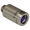 |
These fiber collimation packages are pre-aligned to collimate light from an FC/PC-, FC/APC-, or SMA-terminated fiber. Each collimation package is factory aligned to provide diffraction-limited performance for wavelengths ranging from 405 nm to 4.55 µm. Although it is possible to use the collimator at detuned wavelengths, they will only perform optimally at the design wavelength due to chromatic aberration, which causes the effective focal length of the aspheric lens to have a wavelength dependence. |
| Air-Spaced Doublet, Large Beam Collimators | 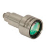 |
For large beam diameters (Ø5.3 - Ø8.5 mm), Thorlabs offers FC/APC, FC/PC, and SMA air-spaced doublet collimators. These collimation packages are pre-aligned at the factory to collimate a laser beam propagating from the tip of an FC or SMA-terminated fiber and provide diffraction-limited performance at the design wavelength. |
| Triplet Collimators | 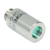 |
Thorlabs' High Quality Triplet Fiber Collimation packages use air-spaced triplet lenses that offer superior beam quality performance when compared to aspheric lens collimators. The benefits of the low-aberration triplet design include an M2 term closer to 1 (Gaussian), less divergence, and less wavefront error. |
| Achromatic Collimators for Multimode Fiber | 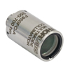 |
Thorlabs' High-NA Achromatic Collimators pair a meniscus lens with an achromatic doublet for high performance across the visible to near-infrared spectrum with low spherical aberration. Designed for use with high-NA multimode fiber, these collimators are ideal for Optogenetics and Fiber Photometry applications. |
| Reflective Collimators |  |
Thorlabs' metallic-coated Reflective Collimators are based on a 90° off-axis parabolic mirror. Mirrors, unlike lenses, have a focal length that remains constant over a broad wavelength range. Due to this intrinsic property, a parabolic mirror collimator does not need to be adjusted to accommodate various wavelengths of light, making them ideal for use with polychromatic light. Our fixed reflective collimators are recommended for collimating single and multimode fiber and coupling into multimode fiber. These collimators are available with UV-enhanced aluminum or protected silver reflective coatings and with FC/PC, FC/APC, or SMA connector compatibility. |
| Compact Reflective Collimators | 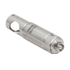 |
Thorlabs' Compact Reflective Collimators incorporate a 90° off-axis parabolic mirror with a protected silver coating. Because the focal length is independent of wavelength for an off-axis parabolic mirror, they are ideal for use with polychromatic light. Our fixed reflective collimators are recommended for collimating single and multimode fiber and coupling into multimode fiber. These collimators are directly compatible with our 16 mm cage system. They are available with FC/PC, FC/APC, or SMA connector inputs. |
| Adjustable Reflective Collimators | 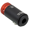 |
Thorlabs' Adjustable Focus Reflective Collimators use a 90° off-axis parabolic (OAP) mirror with a protected silver coating to collimate light from a fiber or couple light into a fiber. The adjustable fiber-to-OAP distance, combined with the OAP having a constant focal length across wavelengths, makes these collimators ideal for optimizing collimation or coupling of polychromatic light with single mode or multimode fiber. These adjustable collimators have a 15.0 mm or 33.0 mm reflected focal length and are available with FC/PC, FC/APC, or SMA connectors. |
| FiberPorts |  |
These compact, ultra-stable FiberPort micropositioners provide an easy-to-use, stable platform for coupling light into and out of FC/PC, FC/APC, or SMA terminated optical fibers. It can be used with single mode, multimode, or PM fibers and can be mounted onto a post, stage, platform, or laser. The built-in aspheric or achromatic lens is available with five different AR coatings and has five degrees of alignment adjustment (3 translational and 2 pitch). The compact size and long-term alignment stability make the FiberPort an ideal solution for fiber coupling, collimation, or incorporation into OEM systems. |
| Adjustable Fiber Collimators |  |
These collimators are designed to connect onto the end of an FC/PC, FC/APC, or SMA connector and contain an AR-coated aspheric lens. The distance between the aspheric lens and the tip of the fiber can be adjusted to compensate for focal length changes or to recollimate the beam at the wavelength and distance of interest. |
| Achromatic Fiber Collimators with Adjustable Focus | 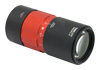 |
Thorlabs' Achromatic Fiber Collimators with Adjustable Focus are designed with an effective focal length (EFL) of 20 mm, 40 mm, or 80 mm, have optical elements broadband AR coated for one of three wavelength ranges, and are available with FC/PC, FC/APC, or SMA905 connectors. A four-element, air-spaced lens design produces superior beam quality (M2 close to 1) and less wavefront error when compared to aspheric lens collimators. These collimators can be used for free-space coupling into a fiber, collimation of output from a fiber, or in pairs for collimator-to-collimator coupling over long distances, which allows the beam to be manipulated prior to entering the second collimator. |
| Zoom Fiber Collimators | 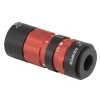 |
These collimators provide a variable focal length between 6 and 18 mm, while maintaining the collimation of the beam. As a result, the size of the beam can be changed without altering the collimation. This universal device saves time previously spent searching for the best suited fixed fiber collimator and has a very broad range of applications. They are offered with FC/PC, FC/APC, or SMA905 connectors with three different antireflection wavelength ranges to choose from. |
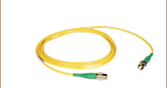
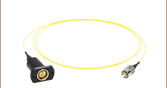
| Single Mode Pigtailed Collimators | 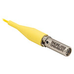 |
Our single mode pigtailed collimators come with one meter of fiber, consist of an AR-coated aspheric lens pre-aligned with respect to a fiber, and are collimated at one of eight wavelengths: 532 nm, 633 nm, 780 nm, 850 nm, 1030 nm, 1064 nm, 1310 nm, or 1550 nm. Although it is possible to use the collimator at any wavelength within the coating range, the coupling loss will increase as the wavelength is detuned from the design wavelength. |
| Polarization Maintaining Pigtailed Collimators | 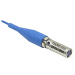 |
Our polarization maintaining pigtailed collimators come with one meter of fiber, consist of an AR-coated aspheric lens pre-aligned with respect to a fiber, and are collimated at one of five wavelengths: 633 nm, 780 nm, 980 nm, 1064 nm, or 1550 nm. Custom wavelengths and connectors are available as well. A line is engraved along the outside of the housing that is parallel to the fast axis. As such, it can be used as a reference when polarized light is launched accordingly. Although it is possible to use the collimator at any wavelength within the coating range, the coupling loss will increase as the wavelength is detuned from the design wavelength. |
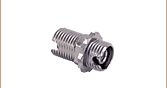
| GRIN Fiber Collimators | 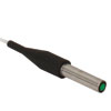 |
Thorlabs offers gradient index (GRIN) fiber collimators that are aligned at a variety of wavelengths from 630 to 1550 nm and have either FC terminated, APC terminated, or unterminated fibers. Our GRIN collimators feature a Ø1.8 mm clear aperture, are AR-coated to ensure low back reflection into the fiber, and are coupled to standard single mode or graded-index multimode fibers. |
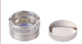
| GRIN Lenses |  |
These graded-index (GRIN) lenses are AR coated for applications at 630, 830, 1060, 1300, or 1560 nm that require light to propagate through one fiber, then through a free-space optical system, and finally back into another fiber. They are also useful for coupling light from laser diodes into fibers, coupling the output of a fiber into a detector, or collimating laser light. Our GRIN lenses are designed to be used with our Pigtailed Glass Ferrules and GRIN/Ferrule sleeves. |
| Item # | Alignment Wavelengtha |
Lens AR Coating |
Waist Diameterb |
Waist Distancec |
Full-Angle Divergenced |
Theoretical Divergence |
NALens | Focal Length at Alignment Wavelength |
Clear Aperture |
Housing Outer Diameter |
Connector Type |
|---|---|---|---|---|---|---|---|---|---|---|---|
| 532 nm | 350 - 700 nm Ravg < 0.5% |
0.38 mm | 1.92 mm | 0.10° +0.01°/-0.00° (1.79 +0.17/-0.00 mrad) |
0.51 | 1.97 mm | 2.0 mm | 4.0 mme | 2.0 mm Narrow Key FC/PC |
||
| 532 nm | 350 - 700 nm Ravg < 0.5% |
3.50 mm | 17.98 mm | 0.01° +0.01°/-0.00° (0.19 +0.17/-0.00 mrad) |
0.15 | 18.04 mm | 5.5 mm | 9.0 mmf |
| Fiber Type | Fiber Length | Insertion Loss | Return Loss | Mode Field Diameter |
|---|---|---|---|---|
| 460HP | 1 m | <0.2 dB | 55 dB | 3.5 µm @ 532 nm |
| Item # | Alignment Wavelengtha |
Lens AR Coating |
Waist Diameterb |
Waist Distancec |
Full-Angle Divergenced |
Theoretical Divergence |
NALens | Focal Length at Alignment Wavelength |
Clear Aperture |
Housing Outer Diameter |
Connector Type |
|---|---|---|---|---|---|---|---|---|---|---|---|
| 633 nm | Ravg < 0.5% |
0.86 mm | 4.09 mm | 0.05° +0.01°/-0.00° |
0.37 | 4.59 mm | 3.6 mm | 5.7 mme | 2.0 mm Narrow Key FC/PC |
||
| 633 nm | 600 - 1050 nm Ravg < 0.5% |
2.05 mm | 11.01 mm | 0.02° +0.01°/-0.00° (0.39 +0.17/-0.00 mrad) |
0.24 | 10.96 mm | 5.4 mm | 9.0 mmf |
| Fiber Type | Fiber Length | Insertion Loss | Return Loss | Mode Field Diameter |
|---|---|---|---|---|
| SM600 | 1 m | <0.2 dB | ≥50 dB | 4.3 µm @ 633 nm |
| Item # | Alignment Wavelengtha |
Lens AR Coating |
Waist Diameterb |
Waist Distancec |
Full-Angle Divergenced |
Theoretical Divergence |
NALens | Focal Length at Alignment Wavelength |
Clear Aperture |
Housing Outer Diameter |
Connector Type |
|---|---|---|---|---|---|---|---|---|---|---|---|
| 780 nm | Ravg < 0.5% |
1.01 mm | 4.13 mm | 0.06° +0.01°/-0.00° |
0.37 | 4.63 mm | 3.6 mm | 5.7 mme | 2.0 mm Narrow Key FC/PC |
||
| 780 nm | 650 - 1050 nm Ravg < 0.5% |
2.41 mm | 11.11 mm | 0.02° +0.01°/-0.00° (0.41 +0.17/-0.00 mrad) |
0.24 | 11.06 mm | 5.4 mm | 9.0 mmf |
| Fiber Type | Fiber Length | Insertion Loss | Return Loss | Mode Field Diameter |
|---|---|---|---|---|
| 780HP | 1 m | <0.2 dB | ≥50 dB | 4.56 μm @ 780 nm |
| Item # | Alignment Wavelengtha |
Lens AR Coating |
Waist Diameterb |
Waist Distancec |
Full-Angle Divergenced |
Theoretical Divergence |
NALens | at Alignment Wavelength |
Clear Aperture |
Housing Outer Diameter |
Connector Type |
|---|---|---|---|---|---|---|---|---|---|---|---|
| 850 nm | 650 - 1050 nm |
2.40 mm | 11.15 mm | 0.03° +0.01°/-0.00° (0.45 +0.17/-0.00 mrad) |
0.24 | 11.10 mm | 5.4 mm | 9.0 mme | 2.0 mm Narrow Key FC/APC |
||
| 850 nm | Ravg < 0.5% |
3.99 mm | 18.32 mm | 0.02° +0.01°/-0.00° (0.27 mrad +0.17/-0.00 mrad) |
0.15 | 18.45 mm | 5.5 mm | 9.0 mme |
| Fiber Type | Fiber Length | Insertion Loss | Return Loss | Mode Field Diameter |
|---|---|---|---|---|
| SM800-5.6-125 | 1 m | <0.2 dB | 55 dB | 5.0 µm @ 850 nm |
| Item # | Alignment Wavelengtha |
Lens AR Coating |
Waist Diameterb |
Waist Distancec |
Full-Angle Divergenced |
Theoretical Divergence |
NALens | Focal Length at Alignment Wavelength |
Clear Aperture |
Housing Outer Diameter |
Connector Type |
|---|---|---|---|---|---|---|---|---|---|---|---|
| 1030 nm | Ravg < 0.5% |
0.44 mm | 1.99 mm | 0.17° +0.01°/-0.00° (2.97 mrad +0.17/-0.00 mrad) |
0.50 | 2.01 mm | 2.0 mm | 4.0 mme | 2.0 mm Narrow Key FC/PC |
||
| CFS5-1030-FC | 1030 nm | 650 - 1050 nm Ravg < 0.5% |
1.02 mm | 4.18 mm | 0.07° +0.01°/-0.00° |
0.39 | 4.67 mm | 3.6 mm | 5.7 mmf | ||
| 1030 nm | 650 - 1050 nm Ravg < 0.5% |
2.44 mm | 11.21 mm | 0.03° +0.01°/-0.00° (0.54 mrad +0.17/-0.00 mrad) |
0.24 | 11.16 mm | 5.4 mm | 9.0 mmg | |||
| 1030 nm | 650 - 1050 nm Ravg < 0.5% |
4.06 mm | 18.44 mm | 0.02° +0.01°/-0.00° (0.32 mrad +0.17/-0.00 mrad) |
0.15 | 18.56 mm | 5.5 mm | 9.0 mmg |
| Fiber Type | Fiber Length | Insertion Loss | Return Loss | Mode Field Diameter |
|---|---|---|---|---|
| HI1060-J9 | 1 m | <0.2 dB | 55 dB | 6.0 μm @ 1030 nm |
| Item # | Alignment Wavelengtha |
Lens AR Coating |
Waist Diameterb |
Waist Distancec |
Full-Angle Divergenced |
Theoretical Divergence |
NALens | Focal Length at Alignment Wavelength |
Clear Aperture |
Housing Outer Diameter |
Connector Type |
|---|---|---|---|---|---|---|---|---|---|---|---|
| CFS2-1064-FC | 1064 nm | 1050 - 1700 nm Ravg < 0.5% |
0.44 mm | 1.99 mm | 0.18° +0.01°/-0.00° (3.07 +0.17/-0.00 mrad) |
0.50 | 2.02 mm | 2.0 mm | 4.0 mme | 2.0 mm Narrow Key FC/PC |
|
| CFS5-1064-FC | 1064 nm | 1050 - 1620 nm Ravg < 0.5% |
1.02 mm | 4.18 mm | 0.08° +0.01°/-0.00° (1.33 +0.17/-0.00 mrad) |
0.39 | 4.67 mm | 3.6 mm | 5.7 mmf | ||
| CFS11-1064-FC | 1064 nm | 1050 - 1620 nm Ravg < 0.5% |
2.44 mm | 11.23 mm | 0.03° +0.01°/-0.00° (0.56 +0.17/-0.00 mrad) |
0.24 | 11.17 mm | 5.4 mm | 9.0 mmg | ||
| CFS18-1064-FC | 1064 nm | 1050 - 1700 nm Ravg < 0.5% |
4.06 mm | 18.45 mm | 0.02° +0.01°/-0.00° (0.33 +0.17/-0.00 mrad) |
0.15 | 18.57 mm | 5.5 mm | 9.0 mmg |
| Fiber Type | Fiber Length | Insertion Loss | Return Loss | Mode Field Diameter |
|---|---|---|---|---|
| HI1060-J9 | 1 m | <0.2 dB | 55 dB | 6.2 μm @ 1064 nm |
| Item # | Alignment Wavelengtha |
Lens AR Coating |
Waist Diameterb |
Waist Distancec |
Full-Angle Divergenced |
Theoretical Divergence |
NALens | Focal Length at Alignment Wavelength |
Clear Aperture |
Housing Outer Diameter |
Connector Type |
|---|---|---|---|---|---|---|---|---|---|---|---|
| CFS2-1310-APC | 1310 nm | 1050 - 1700 nm Ravg < 0.5% |
0.37 mm | 2.00 mm | 0.26° +0.01°/-0.00° (4.52 +0.17/-0.00 mrad) |
0.49 | 2.03 mm | 2.0 mm | 4.0 mme | 2.0 mm Narrow Key FC/APC |
|
| CFS5-1310-APC | 1310 nm | 1050 - 1620 nm Ravg < 0.5% |
0.85 mm | 4.21 mm | 0.11° +0.01°/-0.00° (1.96 +0.17/-0.00 mrad) |
0.38 | 4.70 mm | 3.6 mm | 5.7 mmf | ||
| CFS11-1310-APC | 1310 nm | 1050 - 1620 nm Ravg < 0.5% |
2.04 mm | 11.30 mm | 0.05° +0.01°/-0.00° (0.82 +0.17/-0.00 mrad) |
0.24 | 11.25 mm | 5.4 mm | 9.0 mmg | ||
| CFS18-1310-APC | 1310 nm | 1050 - 1700 nm Ravg < 0.5% |
3.39 mm | 18.55 mm | 0.03° +0.01°/-0.00° (0.49 +0.17/-0.00 mrad) |
0.15 | 18.67 mm | 5.5 mm |
| Fiber Type | Fiber Length | Insertion Loss | Return Loss | Mode Field Diameter |
|---|---|---|---|---|
| SMF-28-J9 | 1 m | <0.2 dB | 55 dB | 9.2 µm @ 1310 nm |
| Item # | Alignment Wavelengtha |
Lens AR Coating |
Waist Diameterb |
Waist Distancec |
Full-Angle Divergenced |
Theoretical Divergence |
NALens | Focal Length at Alignment Wavelength |
Clear Aperture |
Housing Outer Diameter |
Connector Type |
|---|---|---|---|---|---|---|---|---|---|---|---|
| CFS2-1550-APC | 1550 nm | 1050 - 1700 nm Ravg < 0.5% |
0.39 mm | 2.01 mm | 0.29° +0.01°/-0.00° |
0.49 | 2.03 mm | 2.0 mm | 4.0 mme | 2.0 mm Narrow Key FC/APC |
|
| CFS5-1550-APC | 1550 nm | Ravg < 0.5% |
0.90 mm | 4.23 mm | 0.13° +0.01°/-0.00° (2.20 mrad +0.17/-0.00 mrad) |
0.38 | 4.73 mm | 3.6 mm | 5.7 mmf | ||
| CFS11-1550-APC | 1550 nm | 1050 - 1620 nm Ravg < 0.5% |
2.15 mm | 11.36 mm | 0.05° +0.01°/-0.00° (0.92 mrad +0.17/-0.00 mrad) |
0.24 | 11.31 mm | 5.4 mm | 9.0 mmg | ||
| 1550 nm | 1050 - 1700 nm Ravg < 0.5% |
3.57 mm | 18.68 mm | 0.03° +0.01°/-0.00° (0.55 mrad +0.17/-0.00 mrad) |
0.15 | 18.75 mm | 5.5 mm |
| Fiber Type | Fiber Length | Insertion Loss | Return Loss | Mode Field Diameter |
|---|---|---|---|---|
| SMF-28-J9 | 1 m | <0.2 dB | 55 dB | 10.4 µm @ 1550 nm |