Kinesis® K-Cube™ Position Sensing Detector (PSD) Auto Aligner
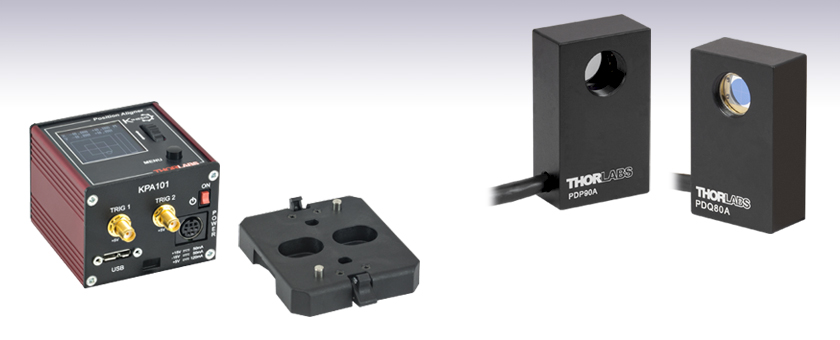
- Enables Auto Alignment in Closed-Loop Mode
- Provides Position Measurement in Open-Loop Mode
- Operation via Local Panel Controls or Remote PC via USB
KPA101
Power Supply
Sold Separately
PDP90A
2D Lateral
Effect PSD
PDQ80A
Segmented
Quadrant PSD
Detectors
Available Separately
Table Mounting Plate
(Included with KPA101)

Please Wait
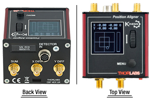
Click to Enlarge
Back and Top Views of the KPA101 K-Cube™
(See the Pin Diagrams Tab for More Information)
| Item # | KPA101 |
|---|---|
| X & Y Difference Outputs | -10 to 10 V, SMA Connectors |
| Sum Output | 0 to 10 V, SMA Connector |
| Position-Sensing Detector Input |
6-Pin Hirose Connectora |
| Closed-Loop Bandwidth |
Up to 1 kHzb |
| Open-Loop Bandwidth (-3.0 dB) |
100 kHz |
| USB Connector Type | USB 3.0 |
| USB Connection Speed | USB 1.1 Full Speed (12 Mbps) |
| Dimensions (W x D x H) |
60.0 mm x 60.0 mm x 49.2 mm (2.36" x 2.36" x 1.94") |
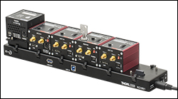
Click to Enlarge
The KCH601 USB Controller Hub with installed K-Cube and T-Cube modules. One KAP101 adapter plate is used for the T-Cube on the hub.
Features
- Compact Footprint: 60.0 mm x 60.0 mm x 49.2 mm
- Auto Alignment of Beam to Center of Sensor when in Closed-Loop Mode
- Beam Position Measurement when in Open-Loop Mode
- OLED Menu and Position Display for Complete On-Unit Control
- Voltage Outputs for Sum, Difference, and Feedback Signals
- Full Kinesis® or APT™ Software Control Suite (See Motion Control Software Tab for Details)
- Software Compatible with other Kinesis and APT Controllers for Integrated Systems Development
- Fully Compatible with Current- and Previous-Generation T-Cube™ Controllers
- Power Supply Sold Separately
- Multi-Axis Expansion Using USB Controller Hubs (Sold Separately)
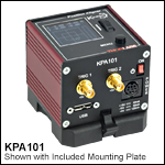
- Magnetic, Clip-On Optical Table Mounting Adapter Included
The KPA101 K-Cube™ Beam Position Aligner is a part of Thorlabs' new and growing Kinesis® line of high-end, compact controllers. It interfaces with our range of Quadrant and Lateral Effect Sensor Heads (see the Typical Application tab above for more information) and can be used either to measure the position of the beam on the sensor (in Open-Loop Mode) or to generate a signal that can be used as the input for an automated beam steering element (in Closed-Loop Mode). When combined with the KPZ101 K-Cube Piezo Drivers, this unit is ideal for such closed-loop beam-steering applications. Please contact Tech Support for details on how the KPA101 can be used with sensors from other manufacturers.
Embedded software allows this unit to communicate with position sensing detectors (PSDs) either using the on-unit menu button, display, and control wheel or using external trigger signals. In addition to the on-unit controls, USB connectivity provides simple PC-controlled operation with two available software platforms: our new Kinesis software package or our legacy APT™ (Advanced Positioning Technology) software package.
The Kinesis Software features .NET controls which can be used by 3rd party developers working in the latest C#, C++, Matlab, LabWindows/CVI, Visual Basic, LabVIEW™, or any .NET compatible languages to create custom applications. Our legacy APT software allows the user to quickly set up complex move sequences with advanced controls made possible via the ActiveX® programming environment. For example, all relevant operating parameters are set automatically by the software for Thorlabs stage and actuator products. For more details on both software packages, please see the Motion Control Software, Kinesis Tutorials, and APT Tutorials tabs.
The unit has a highly compact 60.0 mm x 60.0 mm x 49.2 mm footprint, allowing it to be positioned close to the system for added convenience when using the top panel controls. Tabletop operation also allows minimal drive cable lengths for easier cable management. Each unit contains a front-located power switch that, when turned off, saves all user-adjustable settings. Please note that this switch should always be used to power down the unit. For convenience, a 1.5 m long Type A to Type Micro B USB 3.0 cable is included with the KPA101 cube.
Optical Table Mounting Plate
Each unit comes with a mounting plate that clips onto the base of the module. The plate contains two magnets for temporary placement on an optical table and two counterbores for 1/4"-20 (M6) cap screws for a more permanent placement on the tabletop. Please see the Mounting Options tab for how to mount the plate.
Power Supply Options
The KPA101 K-Cube, which does not ship with a power supply, can be powered using a TPS002 power supply. The TPS002 power supply plugs into a standard wall outlet and provides +15 VDC, -15 VDC, and +5 VDC for up to two K- or T-Cubes.
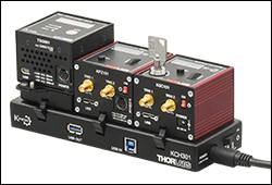
The KPA101 is also compatible with the KCH301 and KCH601 USB Controller Hubs. Our USB Controller Hubs have a single USB connection that provides USB connectivity to all the K-Cubes and T-Cubes connected to the hub. In addition, when the KPA101 is used in the closed-loop mode with beam-steering controllers such as the KPZ101 Piezo Driver K-Cubes, the hub is especially useful since it allows for direct communication between the cubes connected on it. As a result, the feedback signals generated by the KPA101 in the closed-loop mode can be sent directly to the KPZ101 piezo controllers being used to direct the beam steering elements.
| Detectors and Sensors | ||
|---|---|---|
| K-Cube Beam Position Aligner | Lateral Effect Position Sensor | Quadrant Position Detectors |
SUM, LV OUT X DIFF, and LV OUT Y DIFFSMA Female |
TRIG 1SMA Female |
TRIG 2SMA Female |
 |
 |
 |
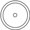
| 3 connectors output signals proportional to the total amount of light hitting the detector (SUM), left-minus-right (LV OUT X DIFF), & top-minus-bottom (LV OUT Y DIFF) for X- and Y-axis alignment. Output Impedance: 470 Ω X DIFF and Y DIFF: -10 V to +10 V SUM: 0 V to +10 V |
+5 V TTL | +5 V TTL |
| These connectors provide a 5 V logic level input and output that can be configured to support triggering into and out of external devices. Each port can be independently configured to control the logic level or to set the trigger as an input or output. Impedance when Configured as Input: 100 kΩ Impedance when Configured as Output: 620 Ω |
||
Power Connector
Mini-DIN Female
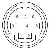
| Pin | Description | Pin | Description |
|---|---|---|---|
| 1 | +5 V (120 mA Max) | 6 | Common Ground |
| 2 | +5 V (120 mA Max) | 7 | Common Ground |
| 3 | -15 V (50 mA Max) | 8 | Common Ground |
| 4 | +15 V (50 mA Max) | Shield | Common Ground |
| 5 | +5 V (120 mA Max) |
Computer Connection*

*The USB 3.0 port is compatible with a USB 2.0 Micro B connector if the Micro B connector is plugged into the shaded region in the photo above. A USB 3.0 type A to type Micro B cable is included with the KPA101.
K-Cube™ Mounting Options
Two options are available to securely mount our K-Cube™ controllers onto an optical table. An optical table mounting plate, provided with every K-Cube, allows for a single controller to be attached to an optical table. Alternatively, three- and six-port USB controller hubs are offered (sold separately) that can mount and power our K-Cube controllers. These options are described in further detail below.
Optical Table Mounting Plate
Each K-Cube unit comes with a mounting plate that clips onto the base of the controller, as shown in the animation below. The plate contains two magnets for temporary placement on an optical table and two counterbores for 1/4"-20 (M6) cap screws for a more permanent placement on the tabletop. Please see the Specs tab for a mechanical drawing of the table mounting plate.
Kinesis USB Controller Hubs
Multiple units can be mounted and connected to a single PC by using the KCH301 or KCH601 USB Controller Hubs. They each consist of two parts: the hub, which can support up to three (KCH301) or six (KCH601) K-Cubes or T-Cubes, and a power supply that plugs into a standard wall outlet. K-Cubes simply clip into place using the provided on-unit clips, while current- and previous-generation T-Cubes require the KAP101 Adapter Plate, shown in the animation below. The hub vastly reduces the number of USB and power cables required when operating multiple controllers.
K-Cube™ Table Mounting Plate
Unlike T-Cubes, every K-Cube includes a mounting plate that clips onto the base of the controller. The plate contains two magnets for temporary placement on an optical table and two counterbores for 1/4"-20 (M6) cap screws for more permanent placement on the tabletop.
Kinesis USB Controller Hubs
3- and 6-Port USB Controller Hubs allow multiple controllers to be connected to one PC for multi-axis applications. K-Cubes can be directly attached to the hubs while T-Cubes require a KAP101 Adapter Plate.
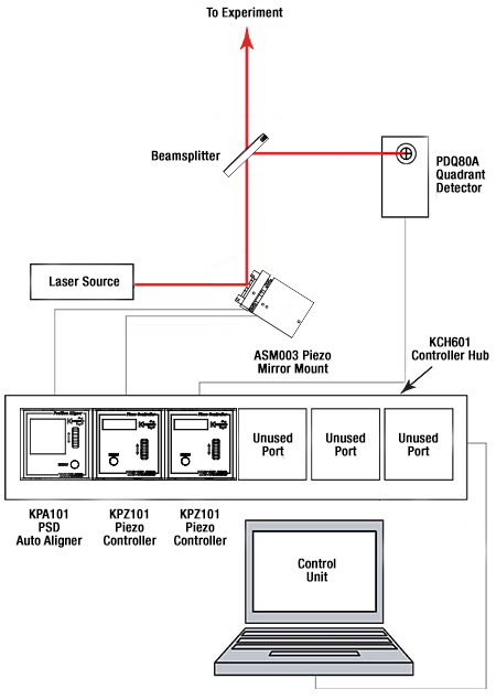
Typical Auto-Alignment Schematic
Example Auto-Alignment Setup
A basic auto-alignment schematic is shown to the right. It consists of a PDQ80A Photodiode Sensor, a KPA101 Beam Position Aligner, two KPZ101 Piezo Drivers, a previous-generation ASM003 two-axis piezo mirror mount (alternative mounts can be found here), a laser source, and a computer. Together, the system is used to position and maintain the laser beam so that it is located at the center of the detector array with respect to the beam's power density.

Click to Enlarge
Example Auto-Alignment Setup
The experimental setup shown above was created based on the schematic to the right. An LDM635 red laser diode module emitting at 635 nm serves as the laser source. The light is incident on a previous-generation ASM003 turning mirror mount, which is mounted on an MBT616D flexure stage (center of photo). The turning mirror's X and Y motions are controlled using two KPZ101 piezo controllers (not shown). Please note that the piezo elements are meant for small beam alignment adjustments. The turning mirror directs light to a BP150 pellicle beamsplitter. The light transmitted by this beamsplitter will continue on to the rest of the experimental setup (not shown) while the reflected light is directed towards the PDQ80A Quadrant Sensor (right of photo), which is controlled by the KPA101 Auto-Aligner (not shown).
It should be noted that when used with older versions of the former generation TPZ001 T-Cubes (i.e., Rev. 1; the revision number is displayed on the LED screen when the T-Cube is booted), the piezo cubes must be connected to the beam position aligner using two external SMA connectors even if a KCH301 or KCH601 Controller Hub or former generation TCH002 Controller Hub is being used. If KPZ101 K-Cubes™ or Rev. 2 TPZ001 T-Cubes are used with a controller hub, the SMA to SMA cables are not needed.
| K-Cube vs. T-Cube Feature Comparison | ||
|---|---|---|
| Feature | KPA101 K-Cube | TPA101 T-Cube |
| Kinesis Software Compatibility | ||
| APT Software Compatibility | ||
| Kinesis USB Controller Hubs Compatibility |
Requires KAP101 Adapter | |
| TCH002 T-Cube USB Controller Hubs Compatibility |
N/A | |
| OLED Position Display | N/A | |
| Power Switch | N/A | |
| Bidirectional SMA Trigger Porta | 2 | N/A |
| SMA SUM, X Diff, and Y Diffa | ||
| Computer Connectiona | USB 3.0 Micro B (USB 2.0 Compliant) |
USB 2.0 Micro B (USB 2.0 Compliant) |
| Included Mounting Plate | ||
| Size (L x W x H) |
60.0 mm x 60.0 mm x 49.2 mm (2.36" x 2.36" x 1.94") |
60.0 mm x 60.0 mm x 49.2 mm (2.36" x 2.36" x 1.94") |
| On-Unit Menu | ||
| Open Loop Mode | ||
| Closed Loop Mode | ||
| Monitor Mode | ||
| Automatic Loop Switching | N/A | |
| Screen Brightness | N/A | |
Introducing Thorlabs' Kinesis® Motion Controllers
A major upgrade to the former-generation T-Cubes, the growing K-Cube line of high-end controllers provides increased versatility not only through the new Kinesis software, but through an overhaul and updating of their physical design and firmware.
Every K-Cube controller includes a digital display. In addition to basic input and output readouts, the KPA101 OLED display hosts a number of menu options that include monitor, closed loop, open loop, and automatic closed/open loop switching. The on-unit wheel and menu button are used to scroll through the available options. Each unit contains a front-located power switch that, when turned off, saves all user-adjustable settings as well as two bidirectional SMA trigger ports that accept or output a 5 V TTL logic signal.
Please see the table to the right for a full comparison of the features offered by our new KPA101 K-Cube and previous-generation TPA101 T-Cube PSD controllers.
Click to Enlarge
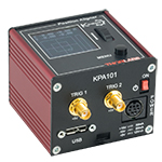
KPA101 K-Cube Kinesis PSD Controller
Kinesis USB Controller Hubs
Complementing our K-Cubes are our Kinesis USB 2.0 controller hubs. With two versions available for three or six K- or T-Cubes, these USB hubs are designed specifically for communication between multiple controllers and the host control PC. These hubs are backward compatible with our T-Cubes.
K-Cubes simply clip into place using the provided on-unit clips, while current- and previous-generation T-Cubes require the KAP101 Adapter Plate, shown in the animation to the below right. The hub vastly reduces the number of USB and power cables required when operating multiple controllers.
K-Cube Table Mounting Plate
Unlike T-Cubes, every K-Cube includes a mounting plate that clips onto the base of the controller. The plate contains two magnets for temporary placement on an optical table and two counterbores for 1/4"-20 (M6) cap screws for more permanent placement on the tabletop.
Kinesis USB Controller Hubs
3- and 6-Port USB Controller Hubs allow multiple controllers to be connected to one PC for multi-axis applications. K-Cubes can be directly attached to the hubs while T-Cubes require a KAP101 Adapter Plate.
Thorlabs offers two platforms to drive our wide range of motion controllers: our Kinesis® software package or the legacy APT™ (Advanced Positioning Technology) software package. Either package can be used to control devices in the Kinesis family, which covers a wide range of motion controllers ranging from small, low-powered, single-channel drivers (such as the K-Cubes™ and T-Cubes™) to high-power, multi-channel, modular 19" rack nanopositioning systems (the APT Rack System).
The Kinesis Software features .NET controls which can be used by 3rd party developers working in the latest C#, Visual Basic, LabVIEW™, or any .NET compatible languages to create custom applications. Low-level DLL libraries are included for applications not expected to use the .NET framework. A Central Sequence Manager supports integration and synchronization of all Thorlabs motion control hardware.

Kinesis GUI Screen
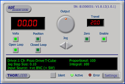
APT GUI Screen
Our legacy APT System Software platform offers ActiveX-based controls which can be used by 3rd party developers working on C#, Visual Basic, LabVIEW™, or any Active-X compatible languages to create custom applications and includes a simulator mode to assist in developing custom applications without requiring hardware.
By providing these common software platforms, Thorlabs has ensured that users can easily mix and match any of the Kinesis and APT controllers in a single application, while only having to learn a single set of software tools. In this way, it is perfectly feasible to combine any of the controllers from single-axis to multi-axis systems and control all from a single, PC-based unified software interface.
The software packages allow two methods of usage: graphical user interface (GUI) utilities for direct interaction with and control of the controllers 'out of the box', and a set of programming interfaces that allow custom-integrated positioning and alignment solutions to be easily programmed in the development language of choice.
A range of video tutorials is available to help explain our APT system software. These tutorials provide an overview of the software and the APT Config utility. Additionally, a tutorial video is available to explain how to select simulator mode within the software, which allows the user to experiment with the software without a controller connected. Please select the APT Tutorials tab above to view these videos.
Software
Kinesis Version 1.14.47
The Kinesis Software Package, which includes a GUI for control of Thorlabs' Kinesis and APT™ system controllers.
Also Available:
- Communications Protocol
Thorlabs' Kinesis® software features new .NET controls which can be used by third-party developers working in the latest C#, Visual Basic, LabVIEW™, or any .NET compatible languages to create custom applications.
C#
This programming language is designed to allow multiple programming paradigms, or languages, to be used, thus allowing for complex problems to be solved in an easy or efficient manner. It encompasses typing, imperative, declarative, functional, generic, object-oriented, and component-oriented programming. By providing functionality with this common software platform, Thorlabs has ensured that users can easily mix and match any of the Kinesis controllers in a single application, while only having to learn a single set of software tools. In this way, it is perfectly feasible to combine any of the controllers from the low-powered, single-axis to the high-powered, multi-axis systems and control all from a single, PC-based unified software interface.
The Kinesis System Software allows two methods of usage: graphical user interface (GUI) utilities for direct interaction and control of the controllers 'out of the box', and a set of programming interfaces that allow custom-integrated positioning and alignment solutions to be easily programmed in the development language of choice.
For a collection of example projects that can be compiled and run to demonstrate the different ways in which developers can build on the Kinesis motion control libraries, click on the links below. Please note that a separate integrated development environment (IDE) (e.g., Microsoft Visual Studio) will be required to execute the Quick Start examples. The C# example projects can be executed using the included .NET controls in the Kinesis software package (see the Kinesis Software tab for details).
 |
Click Here for the Kinesis with C# Quick Start Guide Click Here for C# Example Projects Click Here for Quick Start Device Control Examples |
 |
LabVIEW
LabVIEW can be used to communicate with any Kinesis- or APT-based controller via .NET controls. In LabVIEW, you build a user interface, known as a front panel, with a set of tools and objects and then add code using graphical representations of functions to control the front panel objects. The LabVIEW tutorial, provided below, provides some information on using the .NET controls to create control GUIs for Kinesis- and APT-driven devices within LabVIEW. It includes an overview with basic information about using controllers in LabVIEW and explains the setup procedure that needs to be completed before using a LabVIEW GUI to operate a device.
 |
Click Here to View the LabVIEW Guide Click Here to View the Kinesis with LabVIEW Overview Page |
 |
The APT video tutorials available here fall into two main groups - one group covers using the supplied APT utilities and the second group covers programming the APT System using a selection of different programming environments.
Disclaimer: The videos below were originally produced in Adobe Flash. Following the discontinuation of Flash after 2020, these tutorials were re-recorded for future use. The Flash Player controls still appear in the bottom of each video, but they are not functional.
Every APT controller is supplied with the utilities APTUser and APTConfig. APTUser provides a quick and easy way of interacting with the APT control hardware using intuitive graphical control panels. APTConfig is an 'off-line' utility that allows various system wide settings to be made such as pre-selecting mechanical stage types and associating them with specific motion controllers.
APT User Utility
The first video below gives an overview of using the APTUser Utility. The OptoDriver single channel controller products can be operated via their front panel controls in the absence of a control PC. The stored settings relating to the operation of these front panel controls can be changed using the APTUser utility. The second video illustrates this process.
APT Config Utility
There are various APT system-wide settings that can be made using the APT Config utility, including setting up a simulated hardware configuration and associating mechanical stages with specific motor drive channels. The first video presents a brief overview of the APT Config application. More details on creating a simulated hardware configuration and making stage associations are present in the next two videos.
APT Programming
The APT Software System is implemented as a collection of ActiveX Controls. ActiveX Controls are language-independant software modules that provide both a graphical user interface and a programming interface. There is an ActiveX Control type for each type of hardware unit, e.g. a Motor ActiveX Control covers operation with any type of APT motor controller (DC or stepper). Many Windows software development environments and languages directly support ActiveX Controls, and, once such a Control is embedded into a custom application, all of the functionality it contains is immediately available to the application for automated operation. The videos below illustrate the basics of using the APT ActiveX Controls with LabVIEW, Visual Basic, and Visual C++. Note that many other languages support ActiveX including LabWindows CVI, C++ Builder, VB.NET, C#.NET, Office VBA, Matlab, HPVEE etc. Although these environments are not covered specifically by the tutorial videos, many of the ideas shown will still be relevant to using these other languages.
Visual Basic
Part 1 illustrates how to get an APT ActiveX Control running within Visual Basic, and Part 2 goes on to show how to program a custom positioning sequence.
LabVIEW
Full Active support is provided by LabVIEW and the series of tutorial videos below illustrate the basic building blocks in creating a custom APT motion control sequence. We start by showing how to call up the Thorlabs-supplied online help during software development. Part 2 illustrates how to create an APT ActiveX Control. ActiveX Controls provide both Methods (i.e. Functions) and Properties (i.e. Value Settings). Parts 3 and 4 show how to create and wire up both the methods and properties exposed by an ActiveX Control. Finally, in Part 5, we pull everything together and show a completed LabVIEW example program that demonstrates a custom move sequence.
Part 1: Accessing Online Help
Part 2: Creating an ActiveX Control
Part 3: Create an ActiveX Method
Part 4: Create an ActiveX Property
Part 5: How to Start an ActiveX Control
The following tutorial videos illustrate alternative ways of creating Method and Property nodes:
Create an ActiveX Method (Alternative)
Create an ActiveX Property (Alternative)
Visual C++
Part 1 illustrates how to get an APT ActiveX Control running within Visual C++, and Part 2 goes on to show how to program a custom positioning sequence.
MATLAB
For assistance when using MATLAB and ActiveX controls with the Thorlabs APT positioners, click here.
To further assist programmers, a guide to programming the APT software in LabVIEW is also available here.
| Posted Comments: | |
user
(posted 2024-03-14 20:04:00.35) Hello I've started to use your position aligning devices due to unwanted beam drift by thermal lensing within an AOM(Acousto optic Modulator).
I've connected the Xdiff, Ydiff to the piezo controller( Thorlabs MDT693B). But since the piezo controller only allows external control of positive voltage, the bipolar feature of the position aligner makes it hard to apply to it. Is there any way to apply the position aligner to normal piezo controllers.
Also, when I checked the voltage output. The Xdiff output polarity was the opposite with the software displayed volatge. For example, for Xdiff, when I output 5V on the software, the real output was -5V. However Ydiff output was working well.
Is there something wrong with the product I have?
Best regards. spolineni
(posted 2024-04-02 09:19:52.0) Thank you for reaching out. I will contact you directly to provide further assistance in resolving this matter. Tyler Heritage
(posted 2024-01-09 12:37:20.56) Currently working through a similar situation as stated by others. Trying to write to a csv or other through Labview in order to record position values over time. Could you send me the example file? cstroud
(posted 2024-01-12 11:08:32.0) Thank you for reaching out. I will contact you directly to send over some Labview examples. user
(posted 2023-06-20 07:31:31.933) Hello, I'm using a KPA101 with a PDQ80A sensor and I want to read and extract the X Diff, Y Diff and SUM data using Labview. Can you please send me an example? Thanks, fguzman
(posted 2023-06-23 09:23:11.0) Thanks for your enquiry. We have a Labview guide in our Kinesis Tutorials https://www.thorlabs.com/newgrouppage9.cfm?objectgroup_id=3180&tabname=Kinesis%20tutorials. I will contact you directly for an example in how to plot XY position of KPA101. Natalia Orlova
(posted 2023-04-20 13:48:15.52) Hi there, my name is Natalia Orlova and I'm in charge of the high-throughput two-photon imaging core (two dual beam MesoScopes, a few single beam conventional two-photon microscopes, light sheet microscopes) at the Allen Institute. Currently I'm working on a monitoring software for our systems, and one of the components is the Kinesis cube + PSD detectors. My entire app is in Python: it would be great to have a python adapter for the Kinesis SDK/API. Thank you!
Natalia Orlova JReeder
(posted 2023-04-24 04:19:05.0) Thank you for your enquiry. You should not need a Python Adapter in order to use the KPA and Kinesis SDK/APIs in Python. I have reached out to you to provide examples and further information on how to control the KPA in Python. Bob Cacho
(posted 2023-03-22 22:50:54.32) Purchased a KPA101 auto aligner, PDP90A sensor, and TPS002 power supply - I notice that the sensor wasn't detecting the laser in the -X/-Y or +X/-Y positions in the Kinesis program. I thought the sensor was bad, had it replaced same problem. I notice when the sensor was plug-in to the KPA101 the -15volt power supply when down to -0.1V. The PDP90A requires +/-5volts, does the +/-15volts get converted down to +/-5Volts. My question is what's the problem? do'neill
(posted 2023-04-05 11:50:24.0) Response from Daniel at Thorlabs. I am sorry to hear this I will reach out to you directly to discuss this with you. Bob Cacho
(posted 2023-02-15 20:25:32.063) Hi, I'm using a KPA101 with a PDP90A sensor and I want to
read the X Diff and Y Diff data using Labview. Can you please send me an example, I'm new in Labview?
Thanks, Bob DJayasuriya
(posted 2023-02-16 11:09:18.0) Thank you for your inquiry. We have got in touch with you directly, to help with your application. Matin Jafari
(posted 2022-11-15 09:06:42.733) Hello,
We are using KPA101, and I can see XDIFF, YDIFF, and SUM on the screen. For an application, we have to save these values over long periods of time, for example, five days. How can I do that? I have searched the Kinesis software but i could not find any function or button which does this for me.
Best Regards; cwright
(posted 2022-11-17 05:22:49.0) Response from Charles at Thorlabs: Thank you for your query. The Kinesis GUI software does not have this ability. You can however use the DLLs to request the specific values from the device and then log them to a CSV file. This would require writing a program to do so. We have guides for programming our devices in C# and LabVIEW, which can be found here: https://www.thorlabs.com/newgrouppage9.cfm?objectgroup_id=10285
There is also an example C# program for the KPA101 on our Github, which is found here: https://github.com/Thorlabs/Motion_Control_Examples/blob/main/C%23/KCube/KPA101/Program.cs
The DLLs are found in the installation folder which by default is here: C:\Program Files\Thorlabs\Kinesis. The DotNet_API help file is also in that location and explains the functions you would need. In particular you should look at QuadStatus() to get the PositionDifference and Sum properties. Yi Chu
(posted 2022-11-08 14:48:00.633) Dear Sir/Madam,
We are using KPA101 with PDQ80A, connected to a Linux PC with USB. I wrote a python script using the APT protocol to talk to the KPA101 to get readings of the PDQ80A for a fast steering mirror. Every time the PC sends a request status update message, it takes about 15 ms for the KPA101 to send back a get status update message. This gives around 60 readings per sec which is very slow for a fast steering mirror. Is there any way to improve this delay? Or is there an alternative way to get the readings from KPA frequently over USB without repeatedly sending request status update messages? DJayasuriya
(posted 2022-11-09 09:23:16.0) Thank you for your inquiry. We have got in touch with directly to troubleshoot your issue. ZHU SHAODI
(posted 2022-03-29 14:46:26.517) I can not read the postion data from the screen on KPA101 when using PDP90A, but it is availble through APT software. Seems my controller can only display the raw xdiff and ydiff voltage. Is it an freature or something wrong with my controller? DJayasuriya
(posted 2022-03-30 09:35:34.0) Thank you for your inquiry. On the KAP101 displays the Signals received
from detector, e.g. XDiff and YDiff, Signals output to rear panel SMA connectors and the operation mode i.e open or closed loop. (please see https://www.thorlabs.com/drawings/148cdb3066adcb11-8D9E52F7-EF82-FC97-85BCC31EE31C2412/KPA101-KPA101ManualforAPT.pdf, page 24). Lorenz Keck
(posted 2022-01-13 16:05:35.25) Dear madam or sir,
I am working at the National Institute of Standards and Technology. My group just purchased a KPA101 K-Cube and we use it in combination with a PDP90A and a laser to monitor the position of a stage.
We need to use the labview integration with Kinesis. For this, we set up the communication using the .NET classes in labview and can open and close the communication with our KPA101. However, we cannot figure out, how to extract the position readouts into a labview variable. The required class for this seems to be not accessible.
Is it possible to get technical support on this for our group highly important topic?
It would be great if a technician would reach out to me via email. Thank you a lot for considering to help!
Kind regards,
Lorenz Keck 上月 準平
(posted 2022-01-11 10:45:35.92) APTソフト内の移動距離を手入力で変更できると思いますが、これをエクセルに記録している数値をAPTソフト内の移動距離に入力し、動作させていのですが、可能でしょうか。 Sicheng Lu
(posted 2021-06-07 11:22:50.043) I connect KPA101 to the PC, and the position data can be displayed on Kinesis. How can I save the position data in Excel format? jcater
(posted 2021-06-07 04:30:15.0) Response from Jack at Thorlabs: Thank you for your feedback. Unfortunately at this moment in time it is not possible to extract the KPA101's positional data and save to a .csv file. This will have to be done in a third party application using the .NET APT and by using the KPA101's XYPosition struct to write the X and Y position to a file. I will reach out to you with a LabVIEW example of how to do this. Sicheng Lu
(posted 2021-06-07 11:14:48.19) I connect KPA101 to the PC, and the location data can be displayed on Kinesis. How can I save the location data on the PC in Excel format? YLohia
(posted 2021-08-27 02:32:22.0) Thank you for your feedback. Unfortunately, at this moment in time, it is not possible to extract the KPA101's positional data and save to a .csv file. This will have to be done in a third party application using the .NET APT and by using the KPA101's XYPosition struct to write the X and Y position to a file. We have reached out to you with a LabVIEW example of how to do this. Wade Bortz
(posted 2021-05-12 14:38:09.41) We've got a pair of KPA101's monitoring our sun sensors here on the DKIST solar telescope in Maui. I'm having a problem where I have to climb up on the optical support structure to reset the Control Mode to Monitor each time the power is cycled. Is there any way to store that monitoring setting across power cycles? Thanks! DJayasuriya
(posted 2021-05-24 04:42:09.0) Thank you for your inquiry. yes this is correct, each time the device is power cycled the setting get reset. This is due to a safety feature in the device. We will get in touch with you directly to discuss your application and find a solution. Hong Fang zhang
(posted 2020-11-17 11:24:22.41) when I use KPA101 with senor PDP90A,I cant find the correct configuration to read X Diff and Y Diff in labview. Can u give me a example about this in labview ?
thanks a lot. cwright
(posted 2020-11-17 12:02:39.0) Response from Charles at Thorlabs: Hello and thank you for your query. This would use the PositionDifference property from the PositionAlignerStatus class. I will email you with an example. Francesco Vedovato
(posted 2019-12-17 09:10:05.68) I am Francesco Vedovato from the University of Padua. We used your KPA101 to realize a closed-loop feedback system to drive a piezo-driven mirror (by another company) in an optical system exploiting light at 1064 nm. We used your KPA101 in conjunction with a PSD and an amplifier (by other companies) and it worked well in the first prototype we implemented.
However, I would have more information about the functionality of the KPA101 in "closed-loop mode". In the manual it is stated that, "when the KPA101 unit is switched to closed loop mode, the spot moves towards the center of the display".
It is possible to set (via hardware or software) a different target position on the display with respect to its center? Do you have any other suggestion?
If the question is not clear, please contact me.
Cordially,
Francesco Vedovato
===================================
Francesco Vedovato, PhD
Research Fellow in the QuantumFuture Group
Department of Information Engineering
Via Gradenigo 6/B, 35131 Padova, Italy
University of Padua
Mail: francesco.vedovato@dei.unipd.it
Phone: +39 049 9817490
Mobile Phone: +39 3405470664
Google Scholar link
=================================== cwright
(posted 2019-12-19 06:07:20.0) Response from Charles at Thorlabs: Hello Francesco. Unfortunately you cannot set an offset in the software in order to centre at a specific position in closed-loop mode but I will reach out to you directly to see if we can help find a satisfactory solution for you. steve
(posted 2019-03-05 15:58:11.95) To operate in Monitor Mode, after power cycling the Kinesis KPA101 Position Aligner, its "Mode" must be changed from its power-on default of "Open loop" to "Monitor".
This is done by pressing its MENU button, then rotating its knurled wheel downward
so that its display reads :
"1 Control mode"
Then press its MENU button again so its display now reads :
"Open loop
to select"
Then rotate its knurled wheel either direction until its display reads :
"Monitor"
Then press the MENU button to save "Monitor" as the Mode.
DO NOT let the device auto-timeout and return to its normal display. If that is done, it will show Monitor as its Mode if you go into that menu again but it actually is a bug as of 1/9/2019 and is not in Monitor mode.
If not in Monitor mode, no signal position change will be measured when the control voltage is changed.
As of 1/9/2019, the KPA101 does not remember its Mode setting after power cycling.
Both of these concerns have be made known to Thorlabs rmiron
(posted 2019-03-07 01:01:21.0) Response from Radu at Thorlabs: Hello Steve. As described in the manual, on page 22, the mode indicator is not the first option that appears when one goes to select the operating mode. The sign in the top-right corner of the screen indicates the current operating mode. Regarding your suggestion about the cube starting in the operating mode that was last used, we agree that this would improve user experience, but there are some safety considerations preventing us from implementing the feature. steve
(posted 2018-11-19 13:43:51.02) Is it possible over USB to have an array of positions returned that had been acquired at high rate? This would be an alternative to and a method of obtaining time resolved positions faster than a one-by-one position request over USB. There would need to be a way to specify the acquisition rate and duration, then the acquisition would occur, then USB would send those results. rmiron
(posted 2018-11-20 06:32:14.0) Response from Radu at Thorlabs. Hello, Steve. This depends on the required acquisition rate. The fastest way to keep track of the positional data would be to read the analog signals output by the XDiff and YDiff ports in closed-loop mode. The polling rate will only be limited by the sampling rate of the DAQ card you would employ, or by the 100 kHz bandwidth of the signals. In order to collect the same data over USB, you would need to write a piece of code which uses or .NET API, our C API or our serial communications protocol. I expect the maximum polling rate that you can achieve via USB is on the order of a few hundred Hertz. Writing your own program for controlling KPA101 would of course enable you to control the acquisition duration and rate (as long as it is below that max. achievable figure). I will contact you directly in case further assistance is required. 1611820688
(posted 2018-09-27 06:21:05.997) Hi, I have a PDP30C with the KPA101.I try to interface with this across USB to get the position data (Xdiff,Ydiff,Sum).I've downloaded the Kinesis,and I could see the positon data from the panel in labview.But how can I get the position data out of the panel?Because I just want the position data (Xdiff,Ydiff,Sum),and write control algorithm on my own rather than just click the panel button.
So how I get the position data by labview not in the way of panel? rmiron
(posted 2018-10-01 12:30:33.0) Response from Radu at Thorlabs: You will need to read the Sum and the PositionDifference attributes of the PositionAlignerStatus class, from the KCube.PositionAligner.CLI. I will contact you directly in case further assistance is required. michael.nickerson
(posted 2017-10-18 11:09:29.037) Unfortunately this cannot interface with the TIM101, and thus is unable to control any of the PIA line of piezo controllers. It would be very useful if this KPA101 could somehow control the PIA line of piezo-inertial actuators. AManickavasagam
(posted 2017-10-27 11:42:34.0) Response from Arunthathi at Thorlabs: Thank you for your query. Unfortunately, without external elctronics there is no way to control TIM101 with KPA101 for beam stabilisation/tracking.
We will note this requirement and notify our engineers. tricejp
(posted 2016-06-09 15:54:21.787) Hi,
I have a PDP90a with the TQD001. We are interfacing with this across USB to get the position data (X,Y,Sum,Xpos Ypos...). What is the ~ max sample rate across the USB that we can expect to get from the TQD001? Thanks bwood
(posted 2016-06-13 05:04:47.0) Response from Ben at Thorlabs: Thank you for your feedback. The fundamental limiting factor is the speed of the data exchange between the PC and the TQD001. When the read command is issued, it has to go through whichever software you are using, the USB drivers, and than a USB to serial conversion at the cube. Then the embedded processor has to interpret the command, put together a response and the response has to go through the same channels in reverse order. Although this happens quite quickly, the response is not instantaneous and will be application specific. We would expect a frequency of around 60 readouts per second. pauline.belzanne
(posted 2016-04-22 12:16:02.957) Hi,
I have a PDP90A with a TQD001. I have checked that the voltage delivered by the software for XDIFF and YDIFF was the same on an oscilloscope or a multimeter. I have a good result for YDIFF but for XDIFF I have a very big difference. I've already tried to removed the cable or change the chanel, but I have the same issue.
Do you have an idea to solve this problem?
Thanks. besembeson
(posted 2016-04-22 09:31:25.0) Response from Bweh at Thorlabs USA: I have contacted you to discuss your application and observations further. ysu
(posted 2016-04-18 22:13:52.407) Hi! I have signal displayed on the software, but no voltage output from the SAM. I use it in the monitor mode. It worked fine before, but I don't know why this problem happens now. How can I fix it? bwood
(posted 2016-04-18 10:34:27.0) Response from Ben at Thorlabs: I am sorry to hear about your difficulties here. I will contact you directly for further details, to help us troubleshoot this issue. user
(posted 2013-11-06 11:08:35.927) Hi! Is the signal of the x_Diff and y_Diff output a ground referenced signal or a floating source?
Thanks jlow
(posted 2013-11-14 04:53:22.0) Response from Jeremy at Thorlabs: The signals are referenced to ground. jlow
(posted 2012-11-05 12:01:00.0) Response from Jeremy at Thorlabs: When operating in 'Monitor' mode, the X axis (XDIFF) and Y axis (YDIFF) difference signals from the detector, are
fed through to the rear panel SMA connectors. Using the typical definition of quadrants in circles, the XDIFF is "(Q2 + Q3) - (Q1 + Q4)" and the YDIFF is "(Q1 + Q2) - (Q3 + Q4)". For more detail information on that including schematic diagrams, please refer to Section 4.2 and 4.4 of the manual (http://www.thorlabs.com/Thorcat/17800/TQD001-Manual.pdf). hrudka
(posted 2012-11-05 13:14:45.21) Dear Thorlabs. I have not found information about getting a beam's position of X_DIFF and Y_DIFF and SUM voltages in monitor mode. I am using a 4quadrant diode PDQ80A.
Please help me on this.
Kind regards!
Marek Hudec tcohen
(posted 2012-05-08 09:12:00.0) Response from Tim at Thorlabs: Unfortunately, we currently do not have a document analogous to the APT Motor Controllers Host-Controller Communications Protocol for the TQD001. We are working to provide a protocol document and I will contact you to update you with this information. dpristinski
(posted 2012-05-03 14:48:50.0) Is there a USB communication protocol description for the TQD001 aligner available? Something similar to the motor controllers communication protocol which is on CD. Lou; leichner
(posted 2009-05-21 14:57:37.0) Unfortunately I think we will need additional information regarding your applicaiton. But we can sy that position values state the following:
The system reads the signals Xdiff and Ydiff from the sensor (which are proportional to the light beam position) and outputs Xpos and Ypos (which should really be called Xout and Yout).
Operating modes:
In “monitor” mode: Xpos = Xdiff and Ypos = Ydiff.
In “open loop” mode: Xpos = 0 and Ypos = 0 constant.
In “closed loop” mode: Xpos, Ypos is the output of the PID controller that is trying to maintain zero Xdiff and Ydiff values.
X,Y display modes:
In “difference” mode, the display shows Xdiff and Ydiff, (regardless of the operating mode).
In “position” mode, the display shows Xpos and Ypos, (regardless of the operating mode). m.j.rossewij
(posted 2009-05-20 05:41:09.0) TQD001 manual figure 4.8 suggests that a XPOS setpoint can be subtracted from the normalized XDIFF signal (e.g. to correct for errors due to asymetric beams). However, the APT GUI and software interface do not seem do have this function. Only for open loop is the SetPositionOutputs available to force Xpos to fXPos. (Or has fXPos an undocumented double function, where it is in closed loop subtracted from Xdiff)? srubin
(posted 2008-12-16 12:54:45.0) The PDP90A is listed in the price boxes at the bottom of the page but it is not compatible with the T-Cube sold on this page. technicalmarketing
(posted 2008-06-11 13:35:39.0) Reply from Inge at Thorlabs: We made the following measurements for you. The closed loop bandwidth is up to 200 Hz using 10% of the full positioning range available. Open loop bandwidth (X Difference, Y Difference and Sum signals) is up to 100 kHz (-3dB). lsandstrom
(posted 2008-05-16 01:47:14.0) What is the closed loop / open loop performance on the PDQ80A and TQD001 combination? |

Click to Enlarge
KCH301 USB Controller Hub (Sold Separately) with Installed K-Cube and T-Cube™ Modules (T-Cubes Require the KAP101 Adapter)
- Control Panel and OLED Screen for On-Unit Control and Position Readout
- Two Bidirectional Trigger Ports to Read or Control External Equipment
- Interfaces with Computer Using Included USB Cable
- Fully Compatible with Kinesis® or APT™ Software Packages
- Compact Footprint: 60.0 mm x 60.0 mm x 49.2 mm
- Power Supply Not Included (See Below)
- Not Recommended for Use with Pulsed Lasers
The KPA101 K-Cube™ Beam Position Aligner is designed for use with our range of Quadrant and Lateral Effect Sensor Heads. It features a top-mounted control panel with an OLED screen for on-unit control and position readouts. The OLED display includes a backlight that can be dimmed or turned off using the top panel menu options. The front of the unit contains two bidirectional trigger ports that can be used to read a 5 V external logic signal or output a 5 V logic signal to control external equipment. Each port can be independently configured to control the logic level or to set the trigger as an input or output.
The unit is fully compatible with our new Kinesis software package and our legacy APT control software. Please see the Motion Control Software tab for more information. Please note that this module does not ship with a power supply. Compatible power supplies are listed below.
Operation
The KPA101 K-Cube can be controlled by the manual interface on the top of the unit or via a USB connection to a computer running our new Kinesis software package or our legacy APT (Advanced Positioning Technology) software package. Both interfaces allow the auto aligner to be operated in either an open- or closed-loop mode. In both modes, the K-Cube generates a left-minus-right X difference (X DIFF) signal, a top-minus-bottom Y (Y DIFF) difference signal, and a sum (SUM) signal that are displayed on the target screen.
When in open-loop mode, the X DIFF and Y DIFF difference signals shown on the target screen are not output to the SMA connectors on the back of the unit. Instead, the X DIFF and Y DIFF SMA outputs, which represent X OUT and Y OUT position demand signals, will be fixed at zero or the last closed-loop value. This mode allows for manual alignments on the detector. Once roughly aligned, the unit can be set to closed-loop mode to begin automated alignments of the system.
In the closed-loop mode, a DSP processor inside the KPA101 runs two independent feedback loops that output X DIFF and Y DIFF position demand signals. These signals will be present at the SMA connectors on the back of the unit for use as the inputs to the beam steering elements being used to center the beam on the detector. The proportional, integral, and differential (PID) constants can be adjusted to fine tune the response of the feedback loops to changes in the target position. Floating-point arithmetic allows for a greater range of PID coefficients to be used in the control loop, resulting in higher precision and lower noise (see Appendix B of the manual for details). This increases the range of actuators that can be stabilized using the auto aligner. Furthermore, the unit incorporates a notch filter that can be used to counteract the natural resonance of the specific mechanical system in which the unit is being used. This can stabilize actuators that are prone to mechanical resonances, such as piezo mirror gimbal mounts.
When the unit is controlled via the USB interface, the open-loop output of the unit is also exported digitally to the computer. Please note that stable closed-loop operation can only be achieved with continuous wave (CW) lasers. The KPA101 K-Cube is not recommended for use with pulsed lasers.

- Individual ±15 V/5 V Power Supply
- TPS002: For up to Two K-Cubes™ or T-Cubes™ with Mini-DIN Input*
- USB Controller Hubs Provide Power and Communications
- KCH301: For up to Three K-Cubes or T-Cubes
- KCH601: For up to Six K-Cubes or T-Cubes
The TPS002 supplies power for up to two K-Cubes* or T-Cubes. The cubes still require individual computer connection via USB cable.
The KCH301 and KCH601 USB Controller Hubs each consist of two parts: the hub, which can support up to three (KCH301) or six (KCH601) K-Cubes or T-Cubes, and a power supply that plugs into a standard wall outlet. The hub draws a maximum current of 10 A; please verify that the cubes being used do not require a total current of more than 10 A. In addition, the hub provides USB connectivity to any docked K-Cube or T-Cube through a single USB connection.
For more information on the USB Controller Hubs, see the full web presentation.
*The TPS002 can only support one KNA-VIS or KNA-IR controller or one KLD101 driver and should not be used to power any additional units as that may exceed current limitations.
 Products Home


 Zoom
Zoom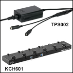
 K-Cube Position Sensing Detector Controller