 Products Home / Actuators, Adjusters, & Transducers / Motorized Actuators / 2" (50 mm) Motorized Actuators
2" (50 mm) Motorized Actuators
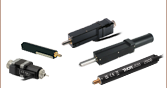
- Piezo Inertia or Stepper Actuators with 50 mm of Travel
- High Load Capacities
- No Backlash
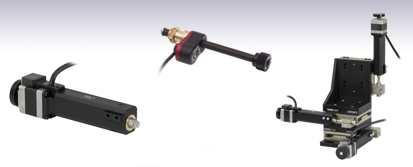
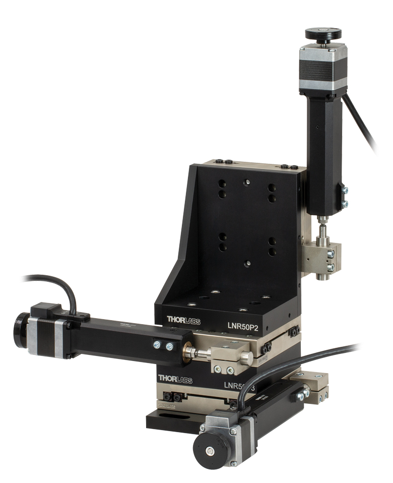
Application Idea
Three LNR50DD Stages
in XYZ Configuration
with DRV250 Motors
DRV250
50 mm Travel
Stepper Motor Actuator
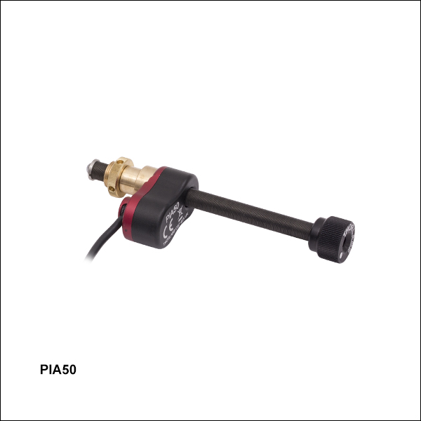
PIA50
50 mm Travel
Piezo Inertia Actuator


Please Wait
| Table 1.1 Available Models | |||
|---|---|---|---|
| Item #a | DRV250 | PIA50 | PIA50VF |
| Travel | 50 mm (1.97") | ||
| Motor Type | 2-Phase Stepper | Piezo Inertia Acuator | |
| Mounting | Two M4 Cap Screws | Ø3/8" (Ø9.525 mm) Barrel | |
| Vacuum Rating | N/A | N/A | 10-6 Torr |
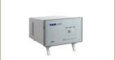
| Required Controller | BSC201, BSC202, BSC203, or MST602 |
KIM001 or KIM101 | |
Features
- 50 mm (1.97") Travel
- Stepper Motor and Piezo Inertia Actuator Models
- Rotating and Non-Rotating Drive Tips
- Replace Micrometers on Manual Stages and Mounts
Thorlabs' Motorized Actuators are designed for use with optical positioning devices. They offer high resolution in lightweight packages, which makes these actuators ideally suited for demanding optical automation applications. These 50 mm (1.97") travel motorized actuators are available with two drive types: 2-phase stepper motors or piezo inertia actuators. A vacuum-compatible model with a piezo inertia actuator provides functionality down to 10-6 Torr. See Table 1.1 for an overview of the available models.
| Table 1.2 Quick Links to Other Motorized Actuators | |||
|---|---|---|---|
| 10 mm (0.39") or Less Travel | 12 mm or 13 mm (1/2") Travel | 25 mm (1") Travel | 50 mm (2") Travel |
DRV225 Actuator
Pin Diagram
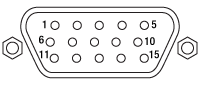
High-Density D-Type Male 15 Pin Connector
15-Pin D-Sub Connector Pin Out
| Pin | Description | Pin | Description |
|---|---|---|---|
| 1 | Limit Grounda | 9 | Ident (for Future Use) |
| 2 | CCW Limit Switch | 10 | +5 V |
| 3 | CW Limit Switch | 11 | Reserved for Future Use |
| 4 | Motor Phase B -ve | 12 | Reserved for Future Use |
| 5 | Motor Phase B +ve | 13 | +5 V |
| 6 | Motor Phase A -ve | 14 | Reserved for Future Use |
| 7 | Motor Phase A +ve | 15 | Ground |
| 8 | Reserved for Future Use | - | - |
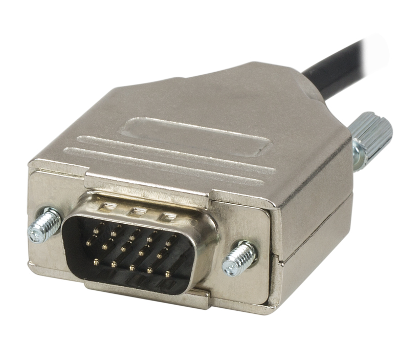
Click to Enlarge
High-Density D-Type Male 15 Pin Connector
Example: Calculating the Linear Displacement per Microstep for Stepper Motor Driven Actuators
The DRV series of stepper motor actuators have 200 full steps per revolution with 2048 microsteps per full step resulting in 409 600 microsteps per revolution of the motor.
Number of microsteps per lead screw revolution is:
Number of Full Steps x Number of Microsteps per Full Step = 200 x 2048= 409 600 Microsteps per Lead Screw Revolution.
The theoretical linear displacement of the lead screw per microstep is:
1.0 mm / 409 600 = 2.4 x 10⁻⁶ mm = 2.4 nm.
Summary of Calculations for Stepper Motor Driven Actuators
| Posted Comments: | |
Peter Hogg
(posted 2021-08-27 13:23:46.94) I'm a graduate student who is trying to build a custom stage with a controller and parts I already have in the lab. I was wondering the compatibility of this actuator (DRV250) with a controller I already have (Sutter MP 285). I have the pin-out for the Sutter's driver and I am comfortable with creating custom wiring but want to make sure I of compatibility before purchasing anything. cwright
(posted 2021-09-02 09:25:24.0) Response from Charles at Thorlabs: Thank you for your query. Unfortunately we are not able to support the use of third party controllers with our actuators and would recommend the use of BSC201 with the DRV250. wmwu
(posted 2016-02-29 19:00:04.997) Dear Officer,
Is "Stepper Motor Drive (DRV014)" able to connect to the "Translation Stage(PT1A)", and to control its motion?
Thanks very much.
Best regards, Alan bwood
(posted 2016-03-01 04:06:43.0) Response from Ben at Thorlabs: Thank you for your feedback. Unfortunately, the DRV014 is not compatible with the PT1A. Among other reasons, the DRV014 barrel size is too large (Ø12 mm) for the PT1A (Ø9.5 mm). The recommended stage to pair with the DRV014 are the 50 mm TravelMax™ stages, and the recommended actuators for the PT1A can be found under the "Actuator" tab on the PT1 series web page. |

 Zoom
Zoom| Key Specificationsa | |
|---|---|
| Travel Range | 50 mm (1.97") |
| Unidirectional Repeatability | ±1.6 µm |
| Bidirectional Repeatability | ±3.9 µm |
| Maximum Pushing Forceb | 180 N |
| Maximum Velocity | 50 mm/s |
| Maximum Acceleration | 50 mm/s2 |
| Limit Switches | Hall Effect |
| Homing Repeatability | ±3.6 µm |
| Feedback | Nonec |
| Motor Type | 2-Phase Stepper Motor |
| Full Step Angle | 1.8° |
| Lead Screw Pitch | 1.0 mm |
| Microsteps per Revolution | 409 600 |
| Actuator Mass | 0.66 kg |
| Compatible Controllersd | BSC201, BSC202, BSC203, or MST602 |
- Designed for Use with LNR50 TravelMax™ Stages
- ±1.6 µm Unidirectional Repeatability
- Maximum Pushing Force: 180 N
- Preload to Eliminate Backlash
- Non-Rotating Tip
- 25 mm Travel Version also Available
The DRV250 offers 50 mm (1.97") of travel and a unidirectional repeatability of ±1.6 μm. When used with one of our stepper motor controllers, the DRV250 achieves a theoretical minimum step size of 2.4 nm and a maximum speed of 50 mm/s.
The hybrid stepper motor, with its rotor that consists of 50 individual magnetic teeth, is ideally suited for micro-stepping applications. Aside from the increase in resolution resulting from increasing the steps per revolution from 200 to 409 600, micro-stepping also ensures smoother low-speed motion by allowing the discrete 1.8° step size to be reduced to much smaller steps, resulting in lower vibrational noise.
The DRV250 stepper motor drive is equipped with a trapezoidal screw thread for more efficient high-load operation than is available from a standard threading.
Click to Enlarge
Figure G1.1 A 3-axis LNR50DD 2" travel stage shown with the manual adjusters replaced by DRV250 actuators.
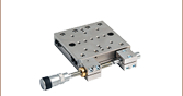
This actuator is designed for use with our 2" TravelMax Manual Stages. To use the DRV250 with these stages, mount the motor to the side of the stage using two 40 mm long M4 cap screws (included). In order to secure the TravelMax stage to a table while using the DRV250 actuator, the LNR50P4(/M) base plate is required.
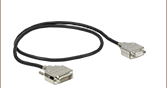
A 500 mm (19.7") cable with a 15-pin D-type connector is attached to the unit to connect the stepper motor to a controller. The unit also comes with a 3 m (9.8 ft) extension cable (item # PAA613). If a shorter cable is needed, the 1 m (3.3 ft) PAA612 cable is available separately.
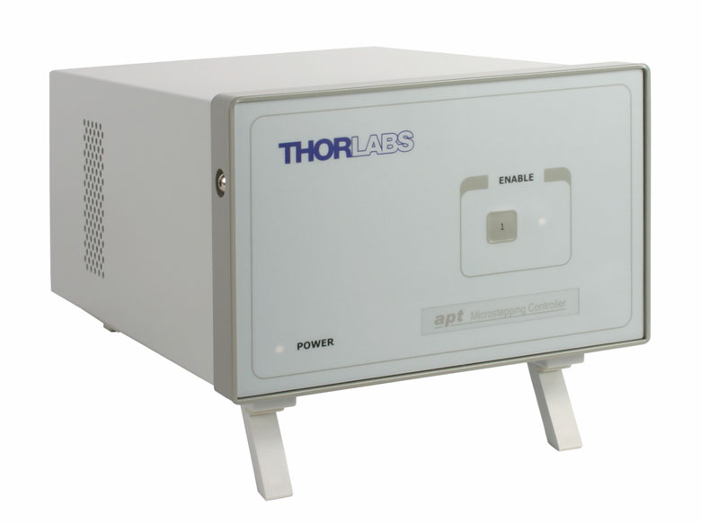
Recommended Controllers:
BSC201, BSC202, or BSC203
- 409 600 Microsteps per Revolution
- 48 V Output at 25 W
- Trapezoidal and
'S-Curve' Velocity Profiles

 Zoom
Zoom| Item #a | PIA50 | |||
|---|---|---|---|---|
| Travel | 50 mm (1.97") | |||
| Typical Step Sizeb,c | 10 - 30 nm (Typ.) ≤30 nm (Max) |
|||
| Step Size Adjustabilityd | Up to 30% | |||
| Max Step Frequency | 2 kHz | |||
| Backlash | None | |||
| Max Active Preloade | 25 N | |||
| Recommended Max Axial Load Capacityf |
2.5 kg (5.5 lbs) | |||
| Speed (Continuous Stepping)b,c |
1.2 - 3.6 mm/min. (Typ.) ≤3.6 mm/min. (Max) |
|||
| Drive Screw | 1/4"-80 Thread, Hard PVD Coated | |||
| Motor Type | Piezoelectric Inertia | |||
| Mounting Feature (Auxiliary) |
Ø3/8" (Ø9.525 mm) Barrel (3/8"-40 Thread with Lock Nut) |
|||
| Operating Temperature | 10 to 40 °C (50 to 104 °F) | |||
| Dimensions | 3.80" x 1.24" x 0.67” (96.6 mm x 31.5 mm x 17.0 mm) |
|||
| Cable Length | 1.0 m (3.28') | |||
| Connector | SMC, Female | |||
| Required Controllerg | KIM001 or KIM101 | |||
- Ø3/8" (Ø9.525 mm) Mounting Barrel for Compatibility with Translation Stages
- Compact Design: 31.5 mm x 17.0 mm (W x H)
- Manual Adjustment via Knob on Adjuster Screw
- 125 V Maximum Operating Voltage
- Also Available in 13 mm and 25 mm Travel Versions
- Ideal for Set-and-Hold Applications that Require High-Resolution Relative Positioning
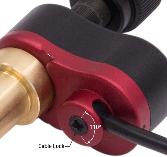
- Control Cable can be Adjusted up to 110° for Space-Constrained Applications
Thorlabs' PIA50 Piezoelectric Inertia Actuator provides high-resolution linear motion control with a long piezo-controlled translation range in a compact package. It can support loads up to 2.5 kg (5.51 lbs) and preloads up to 25 N with typical step size ranging from 10 nm to 30 nm and no backlash. The step size can be adjusted up to 30% to a maximum of approximately 30 nm using the KIM101 Controller and Kinesis software. However, due to the open-loop design, piezo hysteresis, and application conditions such as the direction of travel, the achieved step size of the system can vary by up to 20% and is not normally repeatable. An external feedback system will need to be used to overcome this variance.
This actuator has a Ø3/8" (Ø9.525 mm) barrel that can be mounted in a manual stage that has a Ø3/8" (Ø9.525 mm) mounting clamp. For compatibility with 1/4"-80 or 3/16"-100 threaded mirror mounts see our 10 mm travel piezo inertia actuators. The actuator is self-locking when at rest and when there is no power supplied to the piezo, making the actuator ideal for set-and-hold applications that require nanometer resolution and long-term alignment stability. Manual adjustments can be made using the knob on the adjuster screw, as long as the piezo is not actively translating the screw; the knob is also compatible with 5/64" (2.0 mm) hex keys.
Powered by a 10 mm long discrete piezo stack, the actuator can operate at speeds of up to 3.6 mm/min. The design of the piezo motor will rotate the tip of the lead screw during translation. For information on the design of our piezo inertia "slip-stick" motor actuators, please see the complete presentation here.
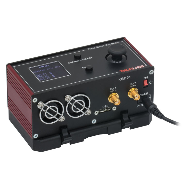
Required Controller
A K-Cube® Piezo Inertia Controller is required to operate our PIA50 Piezo Inertia Actuator; the actuator cannot be operated using a standard piezo controller. The K-Cube controllers have an internal sawtooth voltage signal generator capable of sending sub-millisecond pulses (steps) with controllable amplitudes from 85 V to 125 V. In addition to a single-channel driver, we offer a four-channel driver capable of single- or dual-channel operation, which is ideal for applications involving multiple motorized actuators, such as beam steering.
For more information, please see the full web presentation here.
Required Controller:
KIM001 or KIM101
- KIM001: Single-Channel Output
- KIM101: Four Output Channels, Capable of Multi-Channel Operation
- Standalone Control via Top Panel or PC-Control via USB
- Voltage Output from 85 V to 125 V
Click for Details
Figure G2.1 The control cable can be adjusted up to 110° for space-constrained applications.

 Zoom
Zoom| Item #a | PIA50VF |
|---|---|
| Travel | 50 mm (1.97") |
| Step Sizeb,c | 10 - 30 nm (Typ.) ≤30 nm (Max) |
| Step Size Adjustabilityd | ≤30% |
| Max Step Frequency | 2 kHz |
| Backlash | None |
| Max Active Preloade | 25 N |
| Recommended Max Axial Load Capacityf |
2.5 kg (5.5 lbs) |
| Speed (Continuous Stepping)b,c |
1.2 - 3.6 mm/min. (Typ.) ≤3.6 mm/min. (Max) |
| Drive Screw | 1/4"-80 Thread, Hard PVD Coated |
| Motor Type | Piezoelectric Inertia |
| Mounting Featureg (Auxiliary) |
Ø3/8" (Ø9.525 mm) Barrel (3/8"-40 Thread with Lock Nut) |
| Vacuum Rating | 10-6 Torr |
| Operating Temperature | 5 to 40 °C |
| Max Bakeout Temperature | 130 °C |
| Dimensions | 97.0 mm x 31.5 mm x 17.0 mm (3.82" x 1.24" x 0.67") |
| Mass (Including Cable) | 65 g (2.29 oz) |
| Cable Length | 0.75 m (2.46 ft) Flying Lead for Vacuum, 1.0 m (3.3 ft) Cored Cable for Wiring Outside Chamber |
| Connector | SMC Female |
| Required Controllerh | KIM001 or KIM101 |
- Compact Design: 31.5 mm x 17.0 mm (W x H)
- Manual Adjustment via Knob on Adjuster Screw
- Rated Down to 10-6 Torr
- 125 V Maximum Operating Voltage
- Ø3/8" (Ø9.525 mm) Mounting Barrel for Compatibility with Translation Stages
- Ideal for Set-and-Hold Applications that Require High-Resolution Relative Positioning
- Also Available in 13 mm and 25 mm Travel Versions
Thorlabs' PIA50VF Vacuum-Compatible Piezoelectric Inertia Actuator is rated down to
This actuator has a Ø3/8" (Ø9.525 mm) barrel that can be mounted in a manual stage that has a Ø3/8"(Ø9.525 mm) mounting clamp. For compatibility with 1/4"-100 threaded mirror mounts see our 10 mm travel piezo inertia actuators. The actuator is self-locking when at rest and when there is no power supplied to the piezo, making the actuator ideal for set-and-hold applications that require nanometer resolution and long-term alignment stability. Manual adjustments can be made using the knob on the adjuster screw, as long as the piezo is not actively translating the screw; the knob is also compatible with 5/64" (2.0 mm) hex keys.
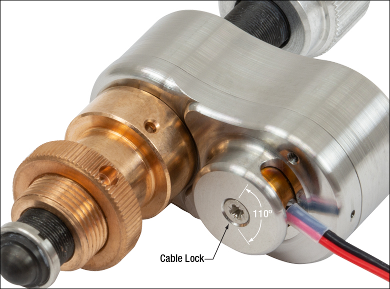
Each actuator has an integrated 0.75 m flying lead, plus 1.0 m of cored cable for wiring outside the vacuum chamber. The flying leads and cored cable lengths can be cut down as needed, but the total length (inside and outside) should not exceed 2.0 m. As shown in Figure G3.1, the flying lead for each actuator can be rotated up to 110° for space-constrained applications.
Powered by a 10 mm long discrete piezo stack, the actuator can operate at speeds of up to 3.6 mm/minute. The design of the piezo motor will rotate the tip of the lead screw during translation. For information on the design of this piezo inertia "slip-stick" motor actuator, please see the complete presentation here.
Required Controller
A KIM001 or KIM101 controller is required to operate our PIA13VF Piezo Inertia Actuator; the actuator cannot be operated using a standard piezo controller. These drivers have an internal sawtooth voltage signal generator capable of sending sub-millisecond pulses (steps) with controllable amplitudes from 85 V to 125 V. The KIM001 and KIM101 controllers offer one and four output channels, respectively.
For more information, please see the full web presentation here.
Required Controller:
KIM001 or KIM101
- KIM001: Single-Channel Output
- KIM101: Four Output Channels, Capable of Multi-Channel Operation
- Standalone Control via Top Panel or PC Control via USB
- Voltage Output from 85 V to 125 V
Click for Details
Figure G3.1 The flying lead can be adjusted up to 110° for space-constrained applications.

 Zoom
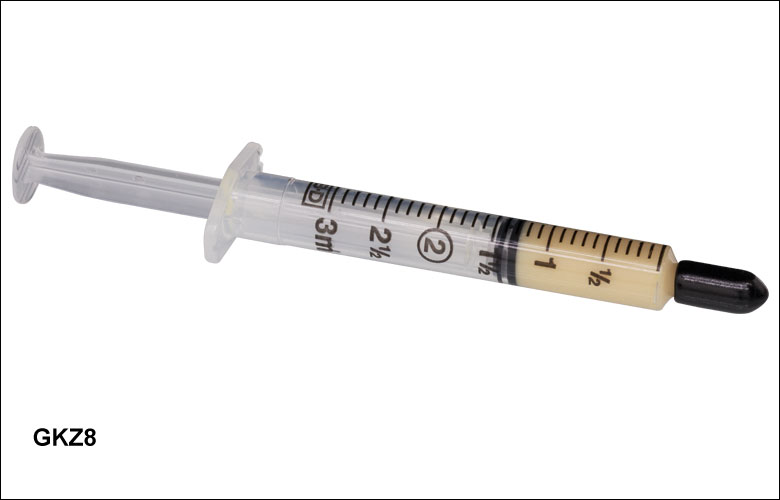
Zoom- 1.5 cc Syringe of Apiezon 100 Grease
- Convenient, Inexpensive Package that Reduces Waste
- Prolongs Lifetime of Actuator
- Ready to Dispense
- Vacuum Compatible to 10-9 Torr
This Apiezon grease has excellent anti-seize properties. It contains PTFE for maximum lubricity and is ideal for re-lubricating the lead screw threads of our ZST, ZFS, and Z9 series actuators. It is supplied in a syringe for easy application and is recommended both for general use and for vacuum applications down to
Note: It is recommended that the lead screw and end ball of the Z9, ZFS, and ZST actuators are lubricated every 10 000 cycles or whenever a squeaking noise is heard during motion.
Thorlabs' DRV, ZST, and ZFS Stepper Motor Actuators, as well as our Z9 DC Servo Motor Actuators, come with cables for connecting to the required controllers. Thorlabs also offers separate cables that may be used as extension cables.
Stepper Motor Cables
Thorlabs offers a variety of cables to support several stepper motor actuator and controller combinations. Supported stepper motors include our ZST, ZFS, and DRV actuators; supported controllers include our BSC benchtop controllers, our KST201 K-Cube® Controller, and our MST602 Rack Control Module. In order to see which cable is compatible with a given combination of stepper motor and controller, please see Table 747A. The pin assignment for each cable is given in the full web presentation here. Please note that these cables cannot be used with motors and controllers that do not match their pin assignment, even if the connectors are the same.
DC Motor Cables
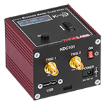
The PAA632 is a 2.5 m cable for our Z9 series of DC motor actuators. This cable is intended to be used with the KDC101 K-Cube DC Servo Motor Controller. The pin assignment for this cable is given in the full web presentation here. Although it uses a 15-pin connector, this cable is not compatible with any of our stepper motors.
| Table 747A Motor and Controller Cable Compatibility | ||
|---|---|---|
| Motor | Controller | Compatible Cable |
  |
 |
PAA614 (1 m) |
| ZST and ZFS Stepper Motor Actuator | KST201 K-Cube Controller | |
 |
|
PAA614 (1 m)a |
| KST201 K-Cube Controller | ||
  |
PAA612 (1 m) or PAA613 (3 m) |
|
| DRV Series Stepper Motor Actuatora | BSC Benchtop Controller and MST602 Rack Controller |
|
 |
 |
PAA632 (2.5 m) |
| Z9 DC Servo Motor Actuator | KDC101 K-Cube Controllerb | |