 Products Home / Actuators, Adjusters, & Transducers / Motorized Actuators / 1" (25 mm) Travel Motorized Actuators
1" (25 mm) Travel Motorized Actuators
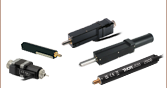
- Piezo Inertia, DC Servo, or Stepper Actuators with 25 mm of Travel
- Load Capacities Up to 55 lbs (25 kg) Available
- Maximum Speeds Up to 50 mm/s Available
- Compatible with a Wide Range of Stages
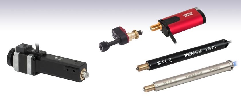
PIA25
Piezo Inertia Actuator
ZFS25B
Compact Stepper Motor Actuator
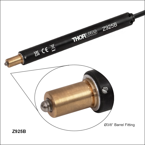
Z925B
DC Servo Actuator
Z925BV
Vacuum-Compatible DC Servo Actuator
DRV225
Trapezoidal Stepper Motor Actuator


Please Wait
| Table 1.1 Available Models | |||||||
|---|---|---|---|---|---|---|---|
| Item #a | ZFS25B | ZST225B | DRV225 | Z925B | Z925BV | PIA25 | PIA25VF |
| Travel | 25 mm (0.98") | ||||||
| Motor Type | 2-Phase Stepper | DC Servo w/ Encoder |
Piezo Inertia Acuator | ||||
| Mounting | Ø3/8" (Ø9.525 mm) Barrel | Two M4 Cap Screws | Ø3/8" (Ø9.525 mm) Barrel | ||||
| Vacuum Rating | N/A | N/A | 10-6 Torr | N/A | 10-6 Torr | ||
| Required Controller | KST201 | BSC201, BSC202, BSC203, or MST602 |
KDC101 | KIM001 or KIM101 | |||
Features
- 1" (25 mm) Travel
- Stepper Motor, Servo Motor, and Piezo Inertia Actuator Models
- Rotating and Non-Rotating Drive Tips
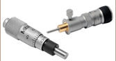
- Replace Micrometers on Manual Stages and Mounts
Thorlabs' Motorized Actuators are designed for use with optical positioning devices. They offer high resolution in lightweight packages, which makes these actuators ideally suited for demanding optical automation applications. These 1" (25 mm) travel motorized actuators are available with three drive types: 2-phase stepper motors, DC servos with encoders, or piezo inertia actuators. Vacuum-compatible models with DC servos or piezo inertia actuators provide functionality down to 10-6 Torr. See Table 1.1 for an overview of the available models.
| Table 1.2 Quick Links to Other Motorized Actuators | |||
|---|---|---|---|
| 10 mm (0.39") or Less Travel | 12 mm or 13 mm (1/2") Travel | 25 mm (1") Travel | 50 mm (2") Travel |
ZFS25B and ZST225B Actuators
Pin Diagram
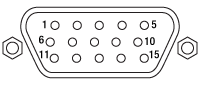
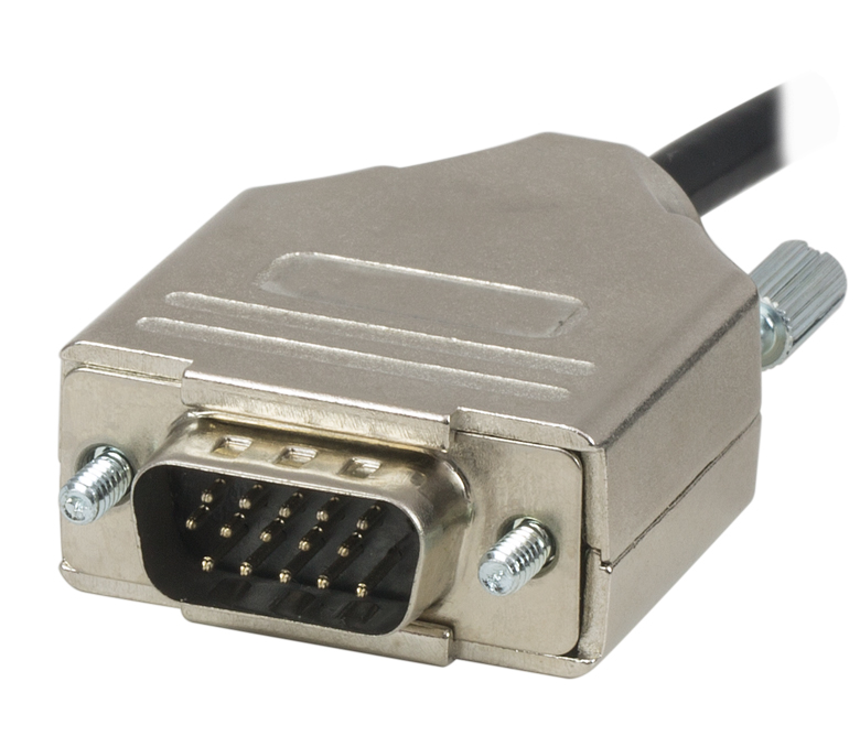
High-Density D-Type Male 15 Pin Connector
15-Pin D-Sub Connector Pin Out
| Pin | Description | Pin | Description |
|---|---|---|---|
| 1 | Limit Ground | 8 | Reserved for Future Use |
| 2 | CCW Limit Switch | 9 | Reserved for Future Use |
| 3 | CW Limit Switch | 10 | Vcc (+5 VDC) |
| 4 | Motor Phase B - | 11 | Reserved for Future Use |
| 5 | Motor Phase B + | 12 | Reserved for Future Use |
| 6 | Motor Phase A - | 13 | Reserved for Future Use |
| 7 | Motor Phase A + | 14 | Reserved for Future Use |
| - | - | 15 | Ground |
Click to Enlarge
High-Density D-Type Male 15 Pin Connector
DRV225 Actuator
Pin Diagram
High-Density D-Type Male 15 Pin Connector
15-Pin D-Sub Connector Pin Out
| Pin | Description | Pin | Description |
|---|---|---|---|
| 1 | Limit Grounda | 9 | Ident (for Future Use) |
| 2 | CCW Limit Switch | 10 | +5 V |
| 3 | CW Limit Switch | 11 | Reserved for Future Use |
| 4 | Motor Phase B -ve | 12 | Reserved for Future Use |
| 5 | Motor Phase B +ve | 13 | +5 V |
| 6 | Motor Phase A -ve | 14 | Reserved for Future Use |
| 7 | Motor Phase A +ve | 15 | Ground |
| 8 | Reserved for Future Use | - | - |
Click to Enlarge
High-Density D-Type Male 15 Pin Connector
Z925B Actuator
Pin Diagram
High-Density D-Type Male 15 Pin Connector
15-Pin D-Sub Connector Pin Out
| Pin | Description | Pin | Description |
|---|---|---|---|
| 1 | Ground (Limit and Vcc) | 9 | Resistive Identification |
| 2 | Forward Limit | 10 | +5 VDC |
| 3 | Reverse Limit | 11 | Encoder Channel A |
| 4 | Reserved for Future Use | 12 | Reserved for Future Use |
| 5 | Motor (-) | 13 | Encoder Channel B |
| 6 | Reserved for Future Use | 14 | Pin 2 Identification EEPROM |
| 7 | Motor (+) | 15 | Pin 1 Identification EEPROM |
| 8 | Reserved for Future Use |
Click to Enlarge
High-Density D-Type Male 15 Pin Connector
Z925BV Actuator
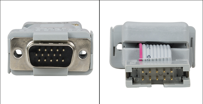
The vacuum-compatible cable integrated with the Z925BV actuator is terminated in a female IDC 10-Pin socket connector. A short converter cable, which adapts this female IDC socket connector to a D-type male HD15 pin connector, is included with the Z925BV actuator to facilitate connecting it to the recommended KDC101 controller. This converter cable, whose terminating connectors are shown below, is not vacuum compatible. Information describing the pin assignments for both the female IDC socket and male D-type HD connector (when it is connected to the female IDC socket connector) follows.
Pin Diagram
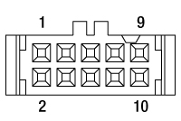
10 Pin Female IDC Socket Connector
(Amphenol T812 Series, 2.54 mm Pitch)
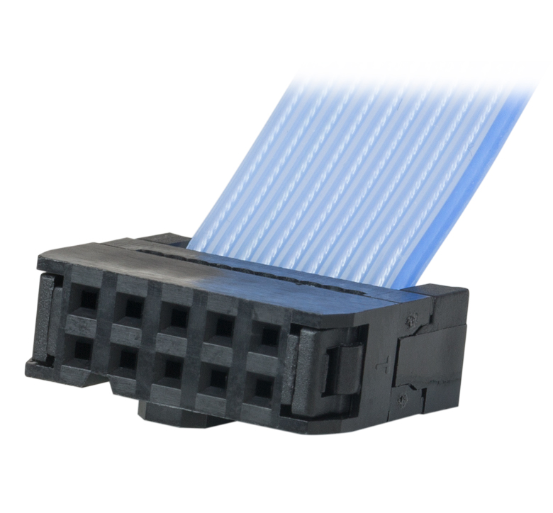
Female IDC 10-Pin Connector Pin Out
| Pin | Description | Pin | Description |
|---|---|---|---|
| 1 | Motor (+) | 6 | Motor (-) |
| 2 | Vcc | 7 | Limit Ground |
| 3 | Channel A | 8 | Reverse Limit |
| 4 | Channel B | 9 | Forward Limit |
| 5 | Ground | 10 | Not Connected |
Pin Diagram
High-Density D-Type Male 15 Pin Connector
Male HDDB15 Connector Pin Out
| Pin | Description | Pin | Description |
|---|---|---|---|
| 1 | Ground (Limit and Vcc) | 8 | Reserved For Future Use |
| 2 | Forward Limit | 9 | Ident Resistor |
| 3 | Reverse Limit | 10 | Vcc (+5 VDC) |
| 4 | Reserved For Future Use | 11 | Encoder Channel A |
| 5 | Motor (-) | 12 | Reserved for Future Use |
| 6 | Reserved for Future Use | 13 | Encoder Channel B |
| 7 | Motor (+) | 14, 15 | Reserved For Future Use |
Click to Enlarge
Connectors terminating the converter cable. The image on the left shows the high-density D-type male 15-pin connector, and the image on the right shows the 10-pin male IDC socket connector.
Example: Calculating the Linear Displacement per Microstep for Stepper Motor Driven Actuators
The ZFS series of stepper motor actuators have 24 full steps per revolution. When driven by the KST201 driver, there are 2048 microsteps per full step resulting in 49 152 microsteps per revolution of the motor. The output shaft of the motor goes into a 400:9 (~44.444:1) gear head. This requires the motor to rotate 44.444 times to rotate the 1.0 mm pitch lead screw one revolution, giving a linear displacement of 1.0 mm.
Number of microsteps per lead screw revolution is:
Number of Microsteps x Gearbox Ratio = 49 152 x 44 444 = 2 184 511.5 Microsteps per Lead Screw Revolution.
The theoretical linear displacement of the lead screw per microstep is:
1.0 mm / 2 184 511.5 = 0.46 x 10⁻⁶ mm = 0.46 nm.
Summary of Calculations for Stepper Motor Driven Actuators
| Item # | Required Driver | Full Steps per Revolution | Microsteps per Revolution | Gearbox Ratio | Displacement per Microstepa |
|---|---|---|---|---|---|
| ZFS25B | KST201 | 24 | 49 152 | 44.444:1 | 0.46 nm |
| ZST225B | 40.866:1 | 0.50 nm | |||
| DRV225 | BSC201, BSC202, BSC203, or MST602 |
200 | 409 600 | N/A | 2.4 nm |
Example: Calculating the Encoder Resoution for Z9 Series Servo Motor Driven Actuators
The Z9 series of servo motor driven actuators have 512 encoder counts per revolution of the servo motor. The output shaft of the motor goes into a 67.49:1 planetary gear head, requiring the motor to rotate 67.49 times to rotate the 1.0 mm pitch lead screw one revolution, giving a linear displacement of 1.0 mm.
The number of encoder counts per lead screw revolution is:
Number of Encoder Counts x Gearbox Ratio = 512 x 67.49 = 34 555 Encoder Counts per Lead Screw Revolution.
The theoretical encoder resolution (linear displacement of the lead screw per encoder count) is:
1.0 mm / 34 555 counts = 2.9 x 10⁻⁵ mm = 29 nm.
Summary of Calculations for Servo Motor Driven Actuators
| Item # | Required Driver | Encoder Counts per Revolution | Gearbox Ratio | Encoder Resolution |
|---|---|---|---|---|
| Z925B | KDC101 | 512 | 67.49:1 | 29 nm |
| Z925BV |
| Posted Comments: | |
Upasana Das
(posted 2024-10-03 12:17:22.887) I have been using two Motor Actuator with 25 mm Travel for my APD setup but when they move around 5 mm or more at a stretch it makes a loud whining noise. What can be the possible reason behind this sound and what to do for maintainance of these actuators? spolineni
(posted 2024-10-10 12:30:46.0) Thank you for reaching out. I will personally contact you to assist with troubleshooting the issue with your motor actuator. Franklin Wei
(posted 2024-06-24 18:38:20.267) We have an application which would benefit from a 50 mm version of the Z925B. Is there a chance this could be developed? cstroud
(posted 2024-06-26 11:11:40.0) Thanks for reaching out. I will pass along your feedback to our internal suggestion forum. Yu Chen
(posted 2023-12-10 00:20:42.793) I have the same problem as Martin Tmej mentioned. When connecting ZFS25B to a controller KST101 the actuator reports itself as ZST6(B) model. I noticed in the reply it said that a firmware update for the controller should solve this question. My question is where can I get the firmware update done? Thanks Victor Lorenz Fonfria
(posted 2022-09-08 10:09:28.75) Can I use the actuator Z825B to replace a micrometer in the stage LX30/M? The micrometers in LX30/M have a Ø3/8" barrel, so I guess I can replace them with Z825B, but I would like to have a confirmation. cwright
(posted 2022-09-09 05:17:59.0) Response from Charles at Thorlabs: Thank you for your query. Yes the Z825B could be used with the LX30/M as a replacement for the micrometer. Martin Tmej
(posted 2022-06-22 08:49:54.44) Hello, I connected the ZFS25B to a controller KST101 and the actuator reports itself as ZST6(B) model. There does not fit any calibration. I tried to change the actuator type through Kinesis application, but it does not allow it. Please, how can I change the actuator type?
Thanks, Martin Tmej cwright
(posted 2022-06-23 09:32:47.0) Response from Charles at Thorlabs: Thank you for your query. If the stage is not detected correctly then it may be that the controller requires a firmware update to account for a change of ident device. We will reach out to you to help with this. HYESANG KIM
(posted 2020-04-23 12:05:12.517) KDC101 with Z825B. Wanted to control them with matlab, and it worked a bit successfully.
I can use device.Home() and device.MoveTo(), but device.MoveToAt() or device.MoveContinuous() and several commands are not working with error : "Class 'Thorlabs.MotionControl.KCube.DCServoCLI.KCubeDCServo' does not have the appropriate method, property, field 'MoveToAt'.".
How can I use them? DJayasuriya
(posted 2020-04-24 09:30:11.0) Response from Dinuka at Thorlabs: Thank you for your feedback, I will be in contact with you directly to help troubleshoot your programming issues. himada
(posted 2018-11-04 21:58:18.32) Can we remove the spherical tip and attach another tip? rmiron
(posted 2018-11-05 06:40:18.0) Response from Radu at Thorlabs: Unfortunately, this is not possible with Z825B. I will relay your question internally so that it is taken into account when we design the next iteration of this product. chao.he
(posted 2018-06-07 15:19:34.433) Hi, I am using Z825B and the KDC101 to control. I can understand the calculation process and the resolution. But how could I know how many rotating steps (number on KDC101 display) corresponding to the real distance moving by one direction? For example, if I change the control number from 0 to 0.25 on KDC, what will be the real distance moving by the Z825B induced? Thanks rmiron
(posted 2018-06-11 05:53:03.0) Response from Radu at Thorlabs: I am afraid that I do not know what is the number on KDC101's display that you are referring to. By default, the controller only displays the current position in mm or degrees and the reading should be labelled accordingly. Therefore, no conversion should be necessary. I will contact you directly for clarification purposes. ruby.mchone
(posted 2015-04-24 16:12:26.65) Please provide details on designing the mating part to best press fit the actuator mounting the part. Thank you. bhallewell
(posted 2015-04-27 10:41:06.0) Response from Ben at Thorlabs: Thanks for your request here Ruby. This is dependent upon the size of the acceptance bore of the particular stage you would intend to mount this actuator to. To mount the stage into a 0.5" hole we hold the item RBA1 an adapter which would encompass the 3/8" barrel on the actuator.
I will contact you directly to discuss this. martien.veekens
(posted 2015-03-11 13:53:36.193) Dear Mrs./Mr.
To add these parts in our systems we need some more information. We could not find it in the available datasheets.
Can you inform me about the materials and surface treatments of the below mentioned parts.
ZST225B
NRT150/M
LNR50SE/M
LNR50S/M
Thanks in advance for your help. bhallewell
(posted 2015-03-16 11:40:47.0) Response from Ben at Thorlabs: Thank you for your request for this information. I will contact you directly to see if I can clarify surface detail to wihtin your requirements. mszheng
(posted 2014-09-20 12:23:38.257) I have a brand new ZST225B that becomes scalding hot once plugged in, without any load or movement at all. It is on default settings. This appears to be a defective unit, can you replace it for us? msoulby
(posted 2014-09-22 08:43:29.0) Response from Mike at Thorlabs: Our older model of TST001 and stepper actuators have a different current settings which are set in the APT Config utility. We will contact you directly to learn more about your configuration settings as if these are set incorrectly you could inadvertently supply the incorrect moving and rest currents to the motor causing it to overheat. hamid.jahroudi
(posted 2014-08-04 11:32:48.177) Hello
I need an actuator for moving in 266 nm steps and with constant velocity and minimum error.
I saw "Calculated Minimum Incremental Motion" section but I'm worried about backlash of this apparatus.
Overally, can I use this apparatus for my Goal?
I'm grateful for your help.:) msoulby
(posted 2014-08-05 05:47:52.0) Response from Mike at Thorlabs: The calculated minimum increment is a calculation based on the microstep count of the stepper motor when driven with our TST001 controller. In reality the actual minimum incremental will be much larger than the 0.5nm calculated; this is due to friction, load, mechanical slack in the system and backlash. The actuator is however very capable of moving a very low velocities and sub-micron increments. Our software also has built in backlash correction to compensate for any predictable errors to improve the repeatability of the actuator, this setting can be adjusted by the user or even disabled if necessary. michael.renner
(posted 2014-05-14 16:20:49.24) Is it possible to fit the actuators to the 10mm barrels of the metric stages (PT3/m) somehow? cdaly
(posted 2014-05-22 11:36:38.0) Response from Chris at Thorlabs: It's is not possible to take an existing PT3/M and replace the micrometers with these actuators, but it is possible for us to provide a custom which uses these. Due to the barrel size (10mm) of the metric micrometer used in the standard PT3/M, the hole is to large for the standard 3/8" actuators barrels. This would be possible with the other metric version of the stage though, which do not eed to have the larger hole, such a PT3A or PT1B. olivier.theobald
(posted 2010-11-29 09:49:26.0) I am interested with this product for a precise xy motorized table. Which tables would you recommand for a 25mm travel ? Thorlabs
(posted 2010-11-30 08:55:50.0) Response from Javier at Thorlabs to Olivier: We currently do not have any stages specifically designed to work with the DRV013 actuator. However, you can use it with our LNR50 2" travel stage (http://www.thorlabs.com/NewGroupPage9.cfm?ObjectGroup_ID=2295&pn=LNR50D). I will contact you directly to discuss your application. c.j.lee
(posted 2010-06-17 03:18:36.0) Is the actuator compatible with your babinet-soilet compensators? (e.g. http://www.thorlabs.com/NewGroupPage9.cfm?ObjectGroup_ID=871). If not, is there a way to automate the compensator? Javier
(posted 2010-06-17 09:47:59.0) From Javier at Thorlabs to c.j.lee: You may also be interested in our liquid crystal variable retarder. We offer three different versions which cover the 450-1650 nm wvalength range.(http://www.thorlabs.com/NewGroupPage9.cfm?ObjectGroup_ID=3925&pn=LCR-1-IR1&CFID=2840336&CFTOKEN=81043801) davymooree
(posted 2009-07-31 19:44:48.0) Is this actuator compatible with other motor drivers or only the TDC001? klee
(posted 2009-07-31 23:38:48.0) Response from Ken at Thorlabs to davymooree: These DC Servo Motor Actuators are only compatible with TDC001. |

 Zoom
Zoom| Item # | ZFS25B |
|---|---|
| Travel | 25 mm (0.98") |
| Backlasha | <15 µm |
| Repeatability | <5.0 µm |
| Home Location Accuracy | <5.0 µm |
| Maximum Load Capacity | 40 N (8.99 lb) |
| Speed | 2.0 mm/s (Max) |
| Acceleration | 10 mm/s2 (Max) |
| Gearbox Ratio | 400:9 (Approx 44:1) |
| Limit Switches | Hall Effect Sensor |
| Lead Screw Pitch | 1.0 mm |
| Motor Type | 2-Phase Stepper |
| Microsteps per Revolution of the Motorb |
24 Full Steps 2048 µsteps per Full Step 49 152 µsteps per Revolution |
| Calculated Minimum Incremental Motionc |
0.46 nm |
| Mounting | Ø3/8" (Ø9.525 mm) Barrel |
| Operating Temperature | 5 to 40 °C (41 to 104 °F) |
| Dimensions (L x W x H) | 88.5 mm x 35.0 mm x 19.0 mm (3.48" x 1.38" x 0.75") |
| Cable Length | 0.6 m (2 ft) |
| Connector | HDDB15 |
| Required Controller | KST201 |
- Compact, Bi-Polar Stepper Motor Actuator: 88.5 mm (3.48") Long when Fully Retracted
- Manual Adjustment via Rear-Located Thumbscrew
- Non-Rotating Drive Tip
- Compatible with Stages and Mounts that Accept Ø3/8" (Ø9.525 mm) Barrels
- Also Available in 6 mm and 13 mm Travel Versions
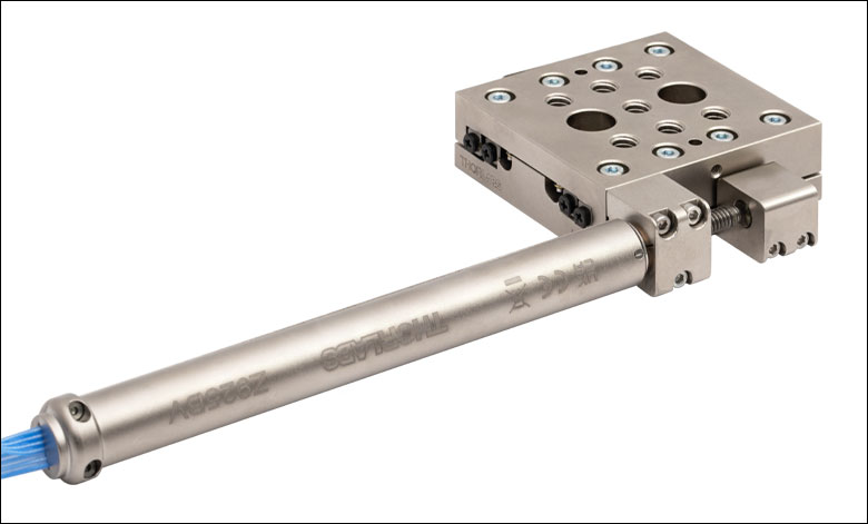
Our ZFS25B Actuator provides smooth, precise linear motion control in a sleek, compact package measuring just 88.5 mm (3.48") in length when fully retracted. This compact profile reduces the distance between the end of the actuator and optomechanical components, keeping the center of mass closer to the contact point than the ZST225B actuator.
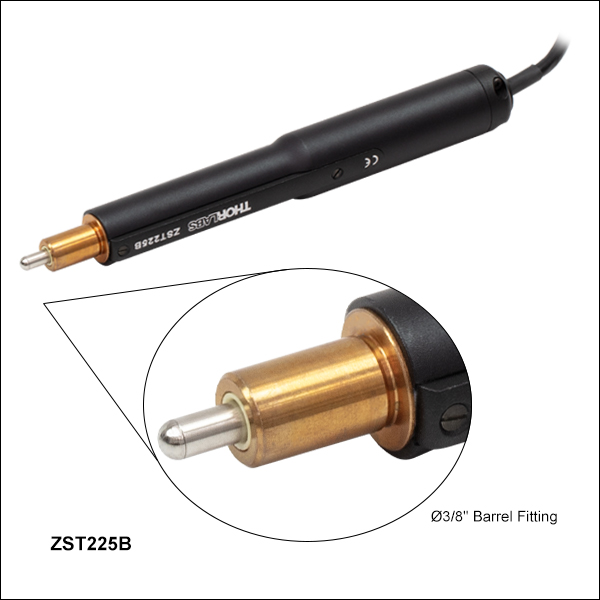
Powered by a small-diameter, dual-phase stepper motor, this actuator operates at speeds of up to 2.0 mm/s. The non-rotating drive tip reduces wear and friction and improves smoothness of motion by removing rotational contact at the tip. If power is not supplied to the actuator, manual adjustment is accomplished using the rear-located thumbscrew. The actuator motor can be damaged if this thumbscrew is rotated while power is being supplied. Mounting is accomplished via a standard Ø3/8" (Ø9.525 mm) barrel.
The ZFS25B Motorized Actuator uses a stepper motor that provides sufficient torque for loads up to 40 N (8.99 lb). The actuator allows very small step sizes over the entire travel range, delivering greater flexibility with low (<15 µm) backlash and fine resolution. The design incorporates a 400:9 gear reduction head which, when combined with the 49 152 microsteps per revolution offered by the KST201 stepper motor driver, gives a theoretical travel per microstep of 0.46 nm (see the Calculations tab for details).
Hall effect limit switches prevent the unit from being overdriven and provide homing capability with an accuracy of <5.0 μm. The ZFS25B ships with 0.6 m (2 ft) of cable terminated in a 15-pin D-Type connector (see the Pin Diagrams tab) that is compatible with our KST201 stepper motor controller. A 1 m (3.3 ft) extension cable (PAA614) is available separately.
The ZFS25B has a standard Ø3/8" (Ø9.525 mm) mounting barrel for fastening into any application compatible with our precision micrometer heads, like the PT1 Single-Axis Translation Stage or the PT3 Three-Axis Translation Stage. The manual adjuster of the LNR25 stage in Figure G1.1 was replaced with a ZFS25B motorized actuator.
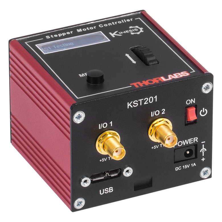
Required Controller:
KST201
- 49 152 Microsteps per Revolution
- 15 V Output at 12 W
- Trapezoidal and
'S-Curve' Velocity Profiles
Click for Details
Figure G1.1 The ZFS25B actuator is a component of the LNR25ZFS Translation Stage.

 Zoom
Zoom| Item # | ZST225B |
|---|---|
| Travel | 25 mm (0.98") |
| Backlasha | <15 µm |
| Repeatability | <5.0 µm |
| Home Location Accuracy | <5.0 µm |
| Maximum Load Capacity | 40 N (8.99 lb) |
| Speed | 2.0 mm/s (Max) |
| Acceleration | 10 mm/s2 (Max) |
| Gearbox Ratio | 29 791:729 (Approx 41:1) |
| Limit Switches | Hall Effect Sensor |
| Lead Screw Pitch | 1.0 mm |
| Motor Type | 2-Phase Stepper |
| Microsteps per Revolution of the Motorb |
24 Full Steps 2048 µsteps per Full Step 49 152 µsteps per Revolution |
| Calculated Minimum Incremental Motion |
0.5 nm |
| Mounting | Ø3/8" (Ø9.525 mm) Barrel |
| Operating Temperature | 5 to 40 °C (41 to 104 °F) |
| Cable Length | 0.6 m (2 ft) |
| Connector | HDDB15 |
| Required Controller | KST201 |
- Non-Rotating Drive Tip
- Bi-Polar Stepper Motor Actuator: 150.5 mm (5.93") Long
- Compatible with Stages and Mounts that Accept Ø3/8" (Ø9.525 mm) Barrels
- Also Available in 6 mm and 13 mm Travel Versions
The ZST225B Actuator provides smooth, precise linear motion control in a package measuring 150.5 mm (5.93") in length. Powered by a small-diameter, dual-phase stepper motor, this actuator operates at speeds of up to 2.0 mm/s. The non-rotating drive tip reduces wear and friction and improves smoothness of motion by removing rotational contact at the tip. Mounting is via a standard Ø3/8" (Ø9.525 mm) barrel.
This actuator uses a stepper motor that provides sufficient torque for loads up to 40 N (8.99 lb). It allows very small step sizes over the entire travel range, delivering greater flexibility with low (<15 µm) backlash and fine resolution. The design incorporates a 41:1 gear reduction head which, when combined with the 49 152 microsteps per revolution offered by the KST201 stepper motor driver, gives a theoretical travel per microstep of 0.5 nm (see the Calculations tab for details).
Hall effect limit switches prevent the unit from being overdriven and provide homing capability with an accuracy of <5.0 μm. The ZST225B ships with 0.6 m (2 ft) of cable terminated in a 15-pin D-Type connector that is compatible with our KST201 stepper motor controller. A 1 m (3.3 ft) extension cable (PAA614) is available separately.
The ZST225B has a standard Ø3/8" (Ø9.525 mm) mounting barrel for fastening into any application compatible with our precision micrometer heads, like the PT1 Single-Axis Translation Stage or the PT3 Three-Axis Translation Stage.
Required Controller:
KST201
- 49 152 Microsteps per Revolution
- 15 V Output at 12 W
- Trapezoidal and
'S-Curve' Velocity Profiles
Click for Details
Figure G2.1 An LNR25 1" travel stage shown with the manual adjuster replaced by a ZST225B actuator.

 Zoom
Zoom| Key Specificationsa | |
|---|---|
| Travel Range | 25 mm (0.98") |
| Unidirectional Repeatability | ±1.6 µm |
| Bidirectional Repeatability | ±3.9 µm |
| Maximum Pushing Forceb | 180 N |
| Maximum Velocity | 50 mm/s |
| Maximum Acceleration | 50 mm/s2 |
| Limit Switches | Hall Effect |
| Homing Repeatability | ±3.6 µm |
| Feedback | Nonec |
| Motor Type | 2-Phase Stepper Motor |
| Full Step Angle | 1.8° |
| Lead Screw Pitch | 1.0 mm |
| Microsteps per Revolution | 409 600 |
| Actuator Mass | 0.58 kg |
| Compatible Controllersd | BSC201, BSC202, BSC203, or MST602 |
- Compatible with LNR50 TravelMax™ Stages
- ±1.6 µm Unidirectional Repeatability
- Maximum Pushing Force: 180 N
- Preload to Eliminate Backlash
- Non-Rotating Tip
- 50 mm Travel Version Also Available
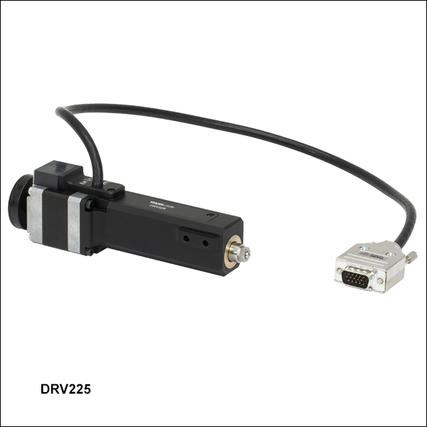
The DRV225 Trapezoidal Stepper Motor Drive offers 25 mm (0.98") of travel and a unidirectional repeatability of ±1.6 μm. When used with one of our stepper motor controllers, this actuator can achieve a theoretical minimum step size of 2.4 nm and a maximum speed of 50 mm/s.
The hybrid stepper motor, with its rotor that consists of 50 individual magnetic teeth, is ideally suited for microstepping applications. Its 200 full steps per revolution are further broken down into 409 600 microsteps. In addition to the resulting increase in resolution, microstepping produces smoother low-speed motion by allowing the discrete 1.8° step size to be reduced to much smaller steps with inherently lower vibrational noise.
The DRV225 stepper motor drive is equipped with a trapezoidal screw thread for more efficient high-load operation than is available from standard threading.
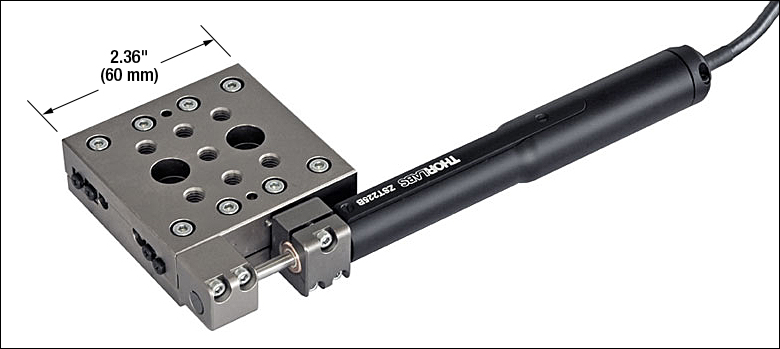
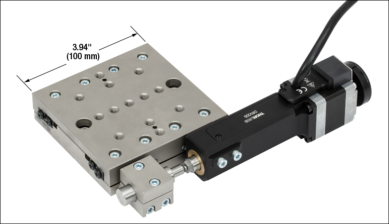
This actuator is compatible with our 2" TravelMax manual stages. To use the DRV225 with these stages, mount the motor to the side of the stage using two 40 mm long M4 cap screws (included).
A 500 mm (19.7") cable with a 15-pin D-type connector is attached to the unit to connect the stepper motor to a controller. The unit also comes with a 3 m (9.8 ft) extension cable (item # PAA613). If a shorter cable is needed, the 1 m (3.3 ft) PAA612 cable is available separately.
Recommended Controllers:
BSC201, BSC202, or BSC203
- 409 600 Microsteps per Revolution
- 48 V Output at 25 W
- Trapezoidal and
'S-Curve' Velocity Profiles
Click for Details
Figure G3.1 An LNR50 Series 2" Travel Stage with the Manual Adjuster Replaced by a DRV225 Actuator

 Zoom
Zoom| Item # | Z925B |
|---|---|
| Travel Range | 25 mm (0.98") |
| Encoder Resolutiona | 34 555 counts/mm (Linear Displacement) |
| Maximum Pushing Force | 45 N |
| Homing Repeatability | ±9 µm |
| Uncompensated Backlash | 13 µm |
| Uncompensated Bidirectional Repeatability | ±7 µm |
| Residual Backlash After Compensationb | 0.7 µm |
| Compensated Bidirectional Repeatability | ±0.8 µm |
| Travel Accuracyc | 40 µm |
| Minimum Repeatable Incremental Movement | 0.2 µm |
| Maximum Speedd | 2.6 mm/s |
| Maximum Acceleration | 4 mm/s2 |
| Phase to Phase Resistance | 33.0 Ω |
| Phase to Phase Inductance | 0.6 mH |
| Tested Lifetimee | >100 000 In and Out Cycles |
| Operating Temperature Range | 41° to 104° F (5° to 40° C) |
| Weight | 0.13 kg |
| Motor Type | DC Servo |
| Cable Length | 485.0 mm (19.09") |
| Required Controller | KDC101 |
- 6 VDC Servo Actuator
- Sub-Micron Resolution
- Maximum Speed: 2.6 mm/s
- Drop-In Replacement for Most 25 mm Manual Actuators
- Compatible with Stages and Mounts that Accept Ø3/8" (Ø9.525 mm) Barrels
- Limit Switches for Zero Datum and Actuator Protection
- Also Available in 6 mm and 12 mm Travel Versions
Our Z9 Series Motorized Actuators are engineered for use with optical positioning devices. They offer high resolution in a lightweight package, which makes these actuators ideally suited for demanding optical laboratory automation applications. The Z925B delivers 25 mm of travel.
Commercial limit switches have been added to provide overdrive protection and accurate home positioning. The incorporated motor is capable of speeds up to 2.6 mm/s, but a maximum speed of 2.3 mm/s is recommended in order to maintain the specified control. The precision of the encoder (512 counts/rev) results in a minimum resolution of about 29 nm (see the Calculations tab for more information).
The Z925B has been designed specifically to replace the manual adjusters in stages and mirror mounts that have a Ø3/8" (Ø9.525 mm) barrel clamp, like the PT1 Single-Axis Translation Stage or the PT3 Three-Axis Translation Stage.
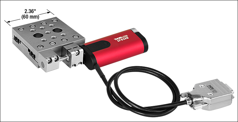
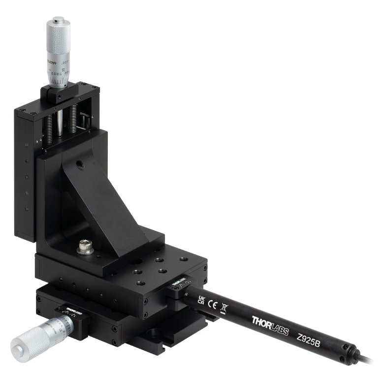
To install, remove the existing manual adjuster from the mount, and fit the replacement Z9 Actuator. Figure G4.1 shows a PT3 three-axis stage with a Z925B fitted to one of the axes.
The units are shipped with one 485.0 mm (19.09") cable. A 2.5 m (8') extension cable (Item # PAA632) is available separately.
For applications with different travel requirements, please see our 6 mm Z906 and 12 mm Z912 actuators. We also offer the Z925BV vacuum-compatible version (sold below), which is rated for use down to 10-6 Torr and is shipped with a 485.0 mm flat ribbon cable, IDC connector, and a converter cable for use with our KDC101 controller.
The KDC101 DC Servo Controller is the required driver for the Z9 series actuators. The latest version of the Kinesis and XA software can be downloaded here. When using the Kinesis software package, firmware version 2.2.8 or higher (included with Kinesis software version 1.14.40 or higher) is required to use the KDC101 with the Z9 actuators. Prior versions of firmware will operate the Z9 actuators but will call the actuators Z8.
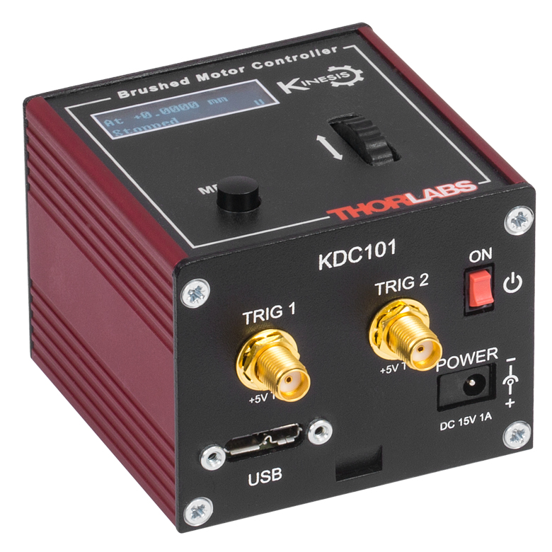
Required Controller:
KDC101
- 34 555 Encoder Counts per Revolution
- 15 V Output at 2.5 W
- Trapezoidal Velocity Profile
Click to Enlarge
Figure G4.1 1" XYZ translation stage with a Z925B motorized actuator replacing the manual adjuster.

 Zoom
Zoom| Item # | Z925BV |
|---|---|
| Travel Range | 25 mm (0.98") |
| Encoder Resolutiona | 34 555 counts/mm (Linear Displacement) |
| Maximum Pushing Force | 45 N |
| Homing Repeatability | ±9 µm |
| Uncompensated Backlash | 13 µm |
| Uncompensated Bidirectional Repeatability | ±7 µm |
| Residual Backlash After Compensationb | 0.7 µm |
| Compensated Bidirectional Repeatability | ±0.8 µm |
| Travel Accuracyc | 40 µm |
| Minimum Repeatable Incremental Movement | 0.2 µm |
| Maximum Speedd | 2.6 mm/s |
| Maximum Acceleration | 4 mm/s2 |
| Maximum Phase to Phase Resistance | 33.0 Ω |
| Maximum Phase to Phase Inductance | 0.6 mH |
| Tested Lifetimee | >100,000 In and Out Cycles |
| Operating Temperature Range | 41° to 104° F (5° to 40° C) |
| Vacuum Rating | 10-6 Torr |
| Weight | 0.094 kg |
| Motor Typef | DC Servo |
| Cable Length | 485.0 mm (19.09") |
| Required Controller | KDC101 |
- Servo Actuator
- Sub-Micron Resolution
- Maximum Operating Speed 2.6 mm/s
- Drop-In Replacement for Most 25 mm Manual Actuators
- Compatible with Ø3/8" (Ø9.525 mm) Barrel-Fitting Stages and Mounts
- Limit Switches for Zero Datum and Actuator Protection
- Rated Down To 10-6 Torr
- Also Available in 6 mm and 12 mm Travel Versions
The Z925BV actuator offers features and specifications similar to the Z925B actuator described above with the added benefit of being vacuum compatible down to 10-6 Torr. They incorporate vacuum-rated servo motors, a phosphorus bronze internal coupling mechanism and mounting bush, and high-vacuum grease.
These actuators are shipped with a 485.0 mm (19.09") vacuum-compatible flat ribbon cable with an IDC connector. A converter cable for use with the KDC101 controller is also supplied, but it is not vacuum compatible and should only be used outside the chamber.
The Z925BV has been designed specifically to replace the manual adjusters in stages and mirror mounts that have a Ø3/8" (Ø9.525 mm) barrel clamp, such as the PT1 Single-Axis Translation Stage or the PT3 Three-Axis Translation Stage.
To install, remove the existing manual adjuster from the mount, and fit the replacement Z9 Actuator. Figure G5.1 shows a Z925BV fitted to a custom vacuum-compatible LNR25M stage. For information about ordering vacuum-compatible versions of our stages, please contact Tech Sales. For applications with different travel requirements, please see our 6 mm Z906V and 12 mm Z912V and Z912BV actuators.
The KDC101 DC Servo Controller is the required driver for the Z9 series actuators. The latest version of the Kinesis and XA software can be downloaded here. When using the Kinesis software package, firmware version 2.2.8 or higher (included with Kinesis software version 1.14.40 or higher) is required to use the KDC101 with the Z9 actuators. Prior versions of firmware will operate the Z9 actuators but will call the actuators Z8.
Required Controller:
KDC101
- 34 555 Encoder Counts per Revolution
- 15 V Output at 2.5 W
- Trapezoidal Velocity Profile
Click to Enlarge
Figure G5.1 Custom vacuum-compatible LNR25 series stages can be ordered for use with Z925BV actuators.

 Zoom
Zoom| Item #a | PIA25 | |||
|---|---|---|---|---|
| Travel | 25 mm (0.98") | |||
| Step Sizeb,c | 10 - 30 nm (Typ.) ≤30 nm (Max) |
|||
| Step Size Adjustabilityd | ≤30% | |||
| Max Step Frequency | 2 kHz | |||
| Backlash | None | |||
| Max Active Preloade | 25 N | |||
| Recommended Max Axial Load Capacityf |
2.5 kg (5.5 lbs) | |||
| Speed (Continuous Stepping)b,c |
1.2 - 3.6 mm/min. (Typ.) ≤3.6 mm/min. (Max) |
|||
| Drive Screw | 1/4"-80 Thread, Hard PVD Coated | |||
| Motor Type | Piezoelectric Inertia | |||
| Mounting Feature (Auxiliary) |
Ø3/8" (Ø9.525 mm) Barrel (3/8"-40 Thread with Lock Nut) |
|||
| Operating Temperature | 10 to 40 °C (50 to 104 °F) | |||
| Dimensions | 2.81" x 1.24" x 0.67" (71.4 mm x 31.5 mm x 17.0 mm) |
|||
| Cable Length | 1.0 m (3.28') | |||
| Connector | SMC, Female | |||
| Required Controllerg | KIM001 or KIM101 | |||
- Ø3/8" (Ø9.525 mm) Mounting Barrel for Compatibility with Translation Stages
- Compact Design: 31.5 mm x 17.0 mm (W x H)
- Manual Adjustment via Knob on Adjuster Screw
- 125 V Maximum Operating Voltage
- Also Available in 13 mm and 50 mm Travel Versions
- Ideal for Set-and-Hold Applications that Require High-Resolution Relative Positioning
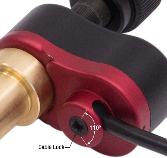
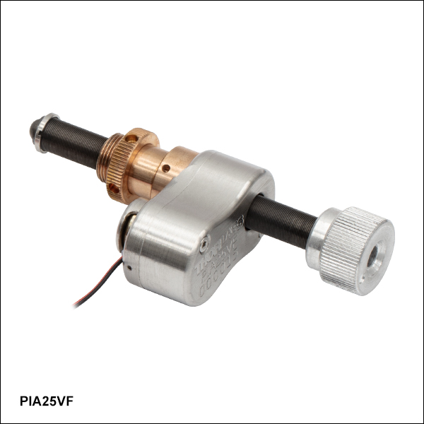
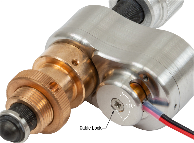
- Control Cable can be Adjusted up to 110° for Space-Constrained Applications
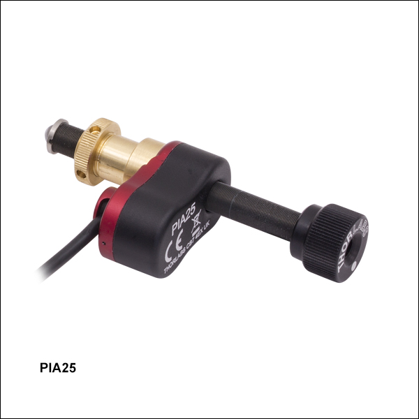
Thorlabs' PIA25 Piezoelectric Inertia Actuator provides high-resolution linear motion control with a long piezo-controlled translation range in a compact package. It can support loads up to 2.5 kg (5.51 lbs) and preloads up to 25 N with typical step size ranging from 10 nm to 30 nm and no backlash. The step size can be adjusted up to 30% to a maximum of approximately 30 nm using the KIM101 Controller and Kinesis software. However, due to the open-loop design, piezo hysteresis, and application conditions such as the direction of travel, the achieved step size of the system can vary by up to 20% and is not normally repeatable. An external feedback system will need to be used to overcome this variance.
This actuator has a Ø3/8" (Ø9.525 mm) barrel that can be mounted in a manual stage that has a Ø3/8" mounting clamp. For compatibility with 1/4"-80 or 3/16"-100 threaded mirror mounts see our 10 mm travel piezo inertia actuators. The actuator is self-locking when at rest and when there is no power supplied to the piezo, making the actuator ideal for set-and-hold applications that require nanometer resolution and long-term alignment stability. Manual adjustments can be made using the knob on the adjuster screw, as long as the piezo is not actively translating the screw; the knob is also compatible with 5/64" (2.0 mm) hex keys.
Powered by a 10 mm long discrete piezo stack, the actuator can operate at speeds of up to 3.6 mm/min. The design of the piezo motor will rotate the tip of the lead screw during translation. For information on the design of our piezo inertia "slip-stick" motor actuators, please see the complete presentation here.
Required Controller
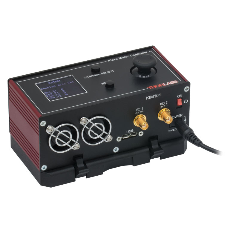
A KIM001 or KIM101 controller is required to operate our PIA25 Piezo Inertia Actuator; the actuator cannot be operated using a standard piezo controller. These drivers have an internal sawtooth voltage signal generator capable of sending sub-millisecond pulses (steps) with controllable amplitudes from 85 V to 125 V. The KIM001 and KIM101 controllers offer one and four output channels, respectively.
For more information, please see the full web presentation here.
Required Controller:
KIM001 or KIM101
- KIM001: Single-Channel Output
- KIM101: Four Output Channels, Capable of Multi-Channel Operation
- Standalone Control via Top Panel or PC-Control via USB
- Voltage Output from 85 V to 125 V
Click for Details
Figure G6.1 The control cable can be adjusted up to 110° for space-constrained applications.

 Zoom
Zoom| Item #a | PIA25VF |
|---|---|
| Travel | 25 mm (0.98") |
| Step Sizeb,c | 10 - 30 nm (Typ.) ≤30 nm (Max) |
| Step Size Adjustabilityd | Up to 30% |
| Max Step Frequency | 2 kHz |
| Backlash | None |
| Max Active Preloade | 25 N |
| Recommended Max Axial Load Capacityf |
2.5 kg (5.5 lbs) |
| Speed (Continuous Stepping)b,c |
1.2 - 3.6 mm/min. (Typ.) ≤3.6 mm/min. (Max) |
| Drive Screw | 1/4"-80 Thread, Hard PVD Coated |
| Motor Type | Piezoelectric Inertia |
| Mounting Featureg (Auxiliary) |
Ø3/8" (Ø9.525 mm) Barrel (3/8"-40 Thread with Lock Nut) |
| Vacuum Rating | 10-6 Torr |
| Operating Temperature | 5 to 40 °C |
| Max Bakeout Temperature | 130 °C |
| Dimensions | 72.0 mm x 31.5 mm x 17.0 mm (2.83" x 1.24" x 0.67") |
| Mass (Including Cable) | 60 g (2.12 oz) |
| Cable Length | 0.75 m (2.46 ft) Flying Lead for Vacuum, 1.0 m (3.3 ft) Cored Cable for Wiring Outside Chamber |
| Connector | SMC Female |
| Required Controllerh | KIM001 or KIM101 |
- Compact Design: 31.5 mm x 17.0 mm (W x H)
- 20 nm Typical Step Size
- Manual Adjustment via Knob on Adjuster Screw
- Rated Down to 10-6 Torr
- 125 V Maximum Operating Voltage
- Ø3/8" (Ø9.525 mm) Mounting Barrel for Compatibility with Translation Stages
- Ideal for Set-and-Hold Applications that Require High-Resolution Relative Positioning
- Also Available in 13 mm and 50 mm Travel Versions
Click for Details
Figure G7.1 The flying lead can be adjusted up to 110° for space-constrained applications.
Thorlabs' PIA25VF Vacuum-Compatible Piezoelectric Inertia Actuator is rated down to 10-6 Torr operation and provides high-resolution linear motion control with a long piezo-controlled translation range in a compact, vacuum-compatible package. It can support loads up to 2.5 kg and preloads up to 25 N with typical step size ranging from 10 nm to 30 nm and no backlash. The step size can be adjusted up to 30% to a maximum of approximately 30 nm using the KIM101 Controller and Kinesis software. However, due to the open-loop design, piezo hysteresis, and application conditions such as the direction of travel, the achieved step size of the system can vary by up to 20% and is not normally repeatable. An external feedback system will need to be used to overcome this variance.
This actuator has a Ø3/8" (Ø9.525 mm) barrel that can be mounted in a manual stage that has a Ø3/8" mounting clamp. For compatibility with 1/4"-100 threaded mirror mounts see our 10 mm travel piezo inertia actuators. The actuator is self-locking when at rest and when there is no power supplied to the piezo, making the actuator ideal for set-and-hold applications that require nanometer resolution and long-term alignment stability. Manual adjustments can be made using the knob on the adjuster screw, as long as the piezo is not actively translating the screw; the knob is also compatible with 5/64" (2.0 mm) hex keys.
Each actuator has an integrated 0.75 m flying lead, plus 1.0 m of cored cable for wiring outside the vacuum chamber. The flying leads and cored cable lengths can be cut down as needed, but the total length (inside and outside) should not exceed 2.0 m. As shown in Figure G7.1, the flying lead for each actuator can be rotated up to 110° for space-constrained applications.
Powered by a 10 mm long discrete piezo stack, the actuator can operate at speeds of up to 3.6 mm/minute. The design of the piezo motor will rotate the tip of the lead screw during translation. For information on the design of this piezo inertia "slip-stick" motor actuator, please see the complete presentation here.

Click to Enlarge
Figure G7.2 PIA25VF Inertia Actuator Used in Place of the Micrometer in our LNR25M(/M) Translation Stage (Contact Tech Sales to Request a Vacuum-Compatible Version of the Stage)
Required Controller
A KIM001 or KIM101 controller is required to operate our PIA25VF Piezo Inertia Actuator; the actuator cannot be operated using a standard piezo controller. These drivers have an internal sawtooth voltage signal generator capable of sending sub-millisecond pulses (steps) with controllable amplitudes from 85 V to 125 V. The KIM001 and KIM101 controllers offer one and four output channels, respectively.
For more information, please see the full web presentation here.
Required Controller:
KIM001 or KIM101
- KIM001: Single-Channel Output
- KIM101: Four Output Channels, Capable of Multi-Channel Operation
- Standalone Control via Top Panel or PC Control via USB
- Voltage Output from 85 V to 125 V

 Zoom
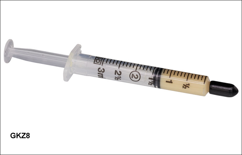
Zoom- 1.5 cc Syringe of Apiezon 100 Grease
- Convenient, Inexpensive Package that Reduces Waste
- Prolongs Lifetime of Actuator
- Ready to Dispense
- Vacuum Compatible to 10-9 Torr
This Apiezon grease has excellent anti-seize properties. It contains PTFE for maximum lubricity and is ideal for re-lubricating the lead screw threads of our ZST, ZFS, and Z9 series actuators. It is supplied in a syringe for easy application and is recommended both for general use and for vacuum applications down to
Note: It is recommended that the lead screw and end ball of the Z9, ZFS, and ZST actuators are lubricated every 10 000 cycles or whenever a squeaking noise is heard during motion.
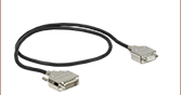
Thorlabs' DRV, ZST, and ZFS Stepper Motor Actuators, as well as our Z9 DC Servo Motor Actuators, come with cables for connecting to the required controllers. Thorlabs also offers separate cables that may be used as extension cables.
Stepper Motor Cables
Thorlabs offers a variety of cables to support several stepper motor actuator and controller combinations. Supported stepper motors include our ZST, ZFS, and DRV actuators; supported controllers include our BSC benchtop controllers, our KST201 K-Cube® Controller, and our MST602 Rack Control Module. In order to see which cable is compatible with a given combination of stepper motor and controller, please see Table 747A. The pin assignment for each cable is given in the full web presentation here. Please note that these cables cannot be used with motors and controllers that do not match their pin assignment, even if the connectors are the same.
DC Motor Cables
The PAA632 is a 2.5 m cable for our Z9 series of DC motor actuators. This cable is intended to be used with the KDC101 K-Cube DC Servo Motor Controller. The pin assignment for this cable is given in the full web presentation here. Although it uses a 15-pin connector, this cable is not compatible with any of our stepper motors.
| Table 747A Motor and Controller Cable Compatibility | ||
|---|---|---|
| Motor | Controller | Compatible Cable |
  |
 |
PAA614 (1 m) |
| ZST and ZFS Stepper Motor Actuator | KST201 K-Cube Controller | |
 |
|
PAA614 (1 m)a |
| KST201 K-Cube Controller | ||
  |
PAA612 (1 m) or PAA613 (3 m) |
|
| DRV Series Stepper Motor Actuatora | BSC Benchtop Controller and MST602 Rack Controller |
|
 |
 |
PAA632 (2.5 m) |
| Z9 DC Servo Motor Actuator | KDC101 K-Cube Controllerb | |