 Products Home / Imaging Systems / OCT Imaging Systems & Components / OCT Components / Interferometers / OCT Common-Path Interferometer
OCT Common-Path Interferometer
INT-COM-1300
- Common-Path Interferometer
- Balanced Detection
- Low Insertion Loss


Please Wait
| Item # | INT-COM-1300 |
|---|---|
| Wavelength Range | 1250 - 1350 nm |
| Insertion Loss: 1300 nm IN to Probea | <1.5 dB (Typ), 2.3 dB (Max) |
| Insertion Loss: 1300 nm IN to VOA INa | <17 dB (Typ), 20 dB (Max) |
| Insertion Loss: 660 nm IN to Probe Porta | <2 dB (Typ), 4 dB (Max) |
| Output Bandwidth (3 dB) | DC - 15 MHz |
| Saturation Powerb | 70 uW @ 1300 nm |
| Maximum Input Power (Damage Threshold)b |
20 mW |
Features
- Low Insertion Loss
- Flat Wavelength Response
- Integrated Balanced Signal Detection with Active Aliasing Filter
- Input for 660 nm Alignment Beam
- Compact Design; Comes Complete with Power Supply
Thorlabs' INT-COM-1300 interferometer is designed to be used inside a swept source OCT system for common-path OCT applications. It integrates a fiber coupler network for use with an external common-path interferometer probe. These couplers are optimized for flat wavelength response and very low polarization dependent coupling losses. The integrated high-gain balanced detector includes an active aliasing filter that minimizes the generation of aliasing frequencies in the digitized fringe signals for improved image quality.
The module is designed for ease of use, and easy integration using the FC/APC angled fiber adapters. Alignment is made easier due to an additional input for a 660 nm aiming laser and a specially designed WDM coupler that combines the swept laser source (1300 nm) and the alignment laser (660 nm).
INT-COM-1300 Interferometer Specifications
| Item # | INT-COM-1300 |
|---|---|
| Optical | |
| Wavelength Range | 1250 - 1350 nm |
| Fiber Type | Corning SMF-28e |
| Fiber Port | FC/APC |
| Insertion Loss: 1300 nm IN to Probea | <1.5 dB (Typ), 2.3 dB (Max) |
| Insertion Loss: 1300 nm IN to VOA INa | <17 dB (Typ), 20 dB (Max) |
| Insertion Loss: 660 nm IN to Probe Porta | <2 dB (Typ), 4 dB (Max) |
| Electrical | |
| Detector Material/Type | InGaAs |
| Detector Wavelength Range | 800 - 1700 nm |
| Maximum Responsivity (Typical) | 1.0 A/W |
| Output Bandwidth (3 dB) | DC - 15 MHz |
| Transimpedance Gain | 51 kV/A |
| DC-Offset | < ±5 mV |
| Saturation Powerb | 70 µW @ 1300 nm |
| Maximum Input Power (Damage Threshold)b | 20 mW |
| Output Impedance | 50 Ω |
| Optical Connectors | FC/APC |
| Electric Output Port | SMA |
| Power Supply | ±12 V @ 250 mA (100/120/230 VAC, 50 - 60 Hz, Switchable) |
| General | |
| Size | 120 mm x 80 mm x 21 mm (4.42" x 3.15" x 0.827") |
Power Monitor Output
SMA Female
0 - 1.8 V (50 Ω) or 0 - 3.6 V (High Z)
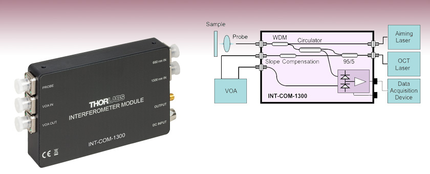
Figure 4.1 shows the schematic diagram of the INT-COM-1300 interferometer's internal optical network and a basic OCT application setup.
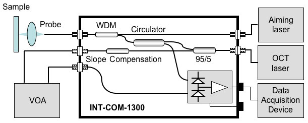
Figure 4.1 Schematic of INT-COM-1300
The internal fiber network of the INT-COM-1300 interferometer is designed for swept source Fourier domain OCT systems in which the signal from both the reference and the sample arm of the interferometer follow a common path configuration. The reflections from both arms are combined to produce the interference fringes which are detected by one channel of the integrated balanced detector. The second channel of the detector may then be used to offset the DC component of the interference signal by using an external variable optical attenuator (VOA) to control the amount of light reaching the second detector channel.
A 95/5 fiber coupler is used to split the incoming light so that 95% of the light is transmitted to a circulator and then passed to the WDM coupler which combines the incoming 1300 nm light with the aiming laser for ease of alignment. From the WDM coupler the light exits the probe port for sample observation. The light reflected from the sample passes back through the WDM coupler and then through the circulator for detection in one channel of the balanced detector.
The 5% of the light which was split from the incoming beam is connected to VOA IN port via a slope compensation coupler. This additional coupler is used to compensate the wavelength dependent coupling ratio. The two coupler design makes the VOA IN signal nearly independent of the OCT laser wavelength allowing broadband DC offset compensation. This is demonstrated by the wavelength response curves shown in Figures 4.2 and 4.3.
Figure 4.2 shows the INT-COM-1300 interferometer's coupling ratio measured from 1300 nm input to the probe ports, while Figure 4.3 shows similar information measured from the input port to input of the VOA port.
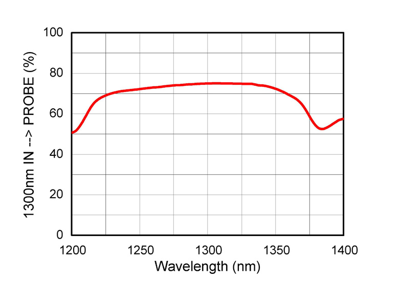 Figure 4.2 Wavelength Response of Coupling from Input to Probe Port
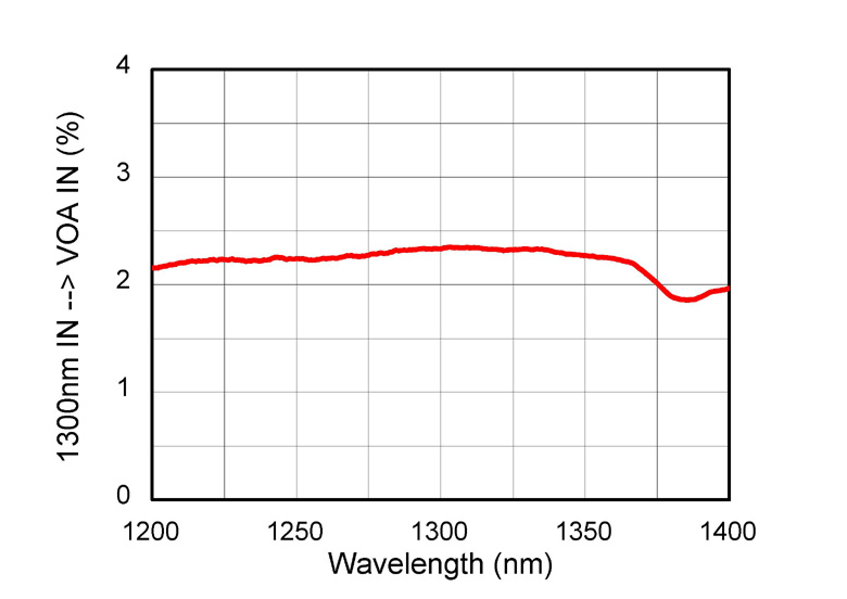 Figure 4.3 Wavelength Response of Coupling from Input to VOA Input Port
| Posted Comments: | |
Wilfried Hortschitz
(posted 2021-09-17 12:24:09.81) Dear sir or madam,
I do have to know what the max. temperature range for operation and storage is for the INT-COM-1300.
BR,
Wilfried dpossin
(posted 2021-09-22 09:20:34.0) Dear Wilfried,
Thank you for your feedback. The device can be stored between -40 and +70°C. All you need is to avoid condensation and therefore stay above the dewpoint. Further information can be found in my previous answer. Wilfried Hortschitz
(posted 2020-11-09 12:10:14.13) Dear Thorlabs-service team,
Can you please provide any data regarding the dependecy or a cross-sensitivity regarding the temperatur?
BR,
Wilfried dpossin
(posted 2020-11-10 03:36:53.0) Dear Wilfried,
Thank you for your feedback. Inside of the given operating temperature between 0°C and 40°C, the performance does not change significantly. However we did not tested the performance outside of the specifications but the responsivity over temperature graph of the photodiode itself tells us, that the overall change between -40°C and 70°C is just 3%. I am reaching out to you to further discuss this. Y Yang
(posted 2020-01-03 16:37:18.26) The output signal is the interference signal of reference light and sample light, right? MKiess
(posted 2020-01-03 08:11:37.0) This is a response from Michael at Thorlabs. Thank you very much for your inquiry. The INT-COM-1300 has an output SMA connector that delivers the measured OCT fringe signal. This signal is a voltage proportional to the difference between the two optical input signals of the balanced detector, and thus the difference between the photocurrents of both photodetectors.
I have contacted you directly to discuss further details. Y Yang
(posted 2019-12-31 09:40:07.987) The reflections from both arms are combined to produce the interference fringes which are detected by one channel of the integrated balanced detector. However, it can not be seen from the schematic diagram that the input of PD is the interference of two beams of light. MKiess
(posted 2020-01-02 10:59:09.0) This is a response from Michael at Thorlabs.
Thank you very much for this feedback. We will discuss whether there is a better representation for this situation. hongsoo88
(posted 2017-07-05 10:44:53.683) Our lab is trying to build swept source OCT and thinking about using OCT common-Path Interferometer(INT-COM-1300).
Can I get a data sheet or user manual for this product? I need more details about this product. swick
(posted 2017-07-05 04:06:38.0) This is a response from Sebastian at Thorlabs. Thank you for the inquiry.
Manuals and data-sheets are directly available on our website. You can click on the red button next to the part number, then a window appears where you can download the manual and other documents. nanjo
(posted 2016-08-18 03:25:11.49) Do you have any tips for optimizing the noise performance with the INT-COM-1300? Our fringe signals after FFT have a lot of noise in them, so SNR is a little low.
How should we tune the VOA? Does the optical path length of the VOA matter (from VOA input to output?
Thank you! swick
(posted 2016-08-18 06:10:44.0) This is a response from Sebastian at Thorlabs. Thank you very much for your inquiry. Basically the VOA ports are used to compensate the DC component in the interference signal. The compensation is done by adjusting the power balance at the balanced detector inputs via a VOA.
Any path length imbalance will introduce a phase shift between the two optical signals detected which will decrease noise reduction performance.
While the inner path lengths are nearly identical the external path length has to be matched. As a rule of thumb, the PROBE-to-sample optical path length shall be half of the optical path length between VOA IN and VOA OUT. Please see also page 19 in the manual.
Unfortunately, the email address which you have left on this feedback is not working. We would like to discuss your questions about noise and your setup in detail. Please use europe@thorlabs.com for contacting us directly. avle
(posted 2016-06-20 02:56:59.263) Will this work with a 50khz sweep rate laser? shallwig
(posted 2016-06-23 05:38:07.0) This is a response from Stefan at Thorlabs. Thank you very much for your inquiry. The frequency of the detected fringe signals is proportional to laser sweep rate, total wavelength sweep range, and the probing interferometer delay. The peak electronic fringe frequency of a sine wave drive laser is: f_peak=-1.57*k *(deltaLambda)*L/(Lambda)^2
The board of the INT-COM-1300 can resolve up to 15 MHz. Depending on the parameters of your laser and setup a laser with a sweep rate of 50kHz can be used. I have contacted you directly to discuss your application in more detail. anthony
(posted 2016-04-09 22:50:03.79) Can you quote for the common path interferometer with 400mhz bandwidth PN INT-COM-1300?
Thank you shallwig
(posted 2016-04-11 03:59:05.0) This is a response from Stefan at Thorlabs. Thank you very much for your inquiry. We will contact you directly to provide you with a quote for this special with 400 MHz bandwidth. jlow
(posted 2012-08-10 09:19:00.0) Response from Jeremy at Thorlabs: You do not need a polarization controller for this because the interferometer does not require polarized light. ggjmlee
(posted 2012-08-10 14:26:33.0) Do I need polraization cotroller to get a signal throught this interferometer? jvigroux
(posted 2011-07-15 11:19:00.0) A response form Julien at Thorlabs: we shoud be able to offer a custom ineterferometer having a bandwidth of 100MHz with a transimpedance gain of 100kV/A. I will contact you directly to see if those values would meet your requirements. avle
(posted 2011-07-14 14:11:25.0) Hi there,
Is it possible to increase the bandwidth of the TIA from 15mhz to 100mhz by adjusting internal values of the TIA circuit?
Thanks! |