 Products Home
K-Cube® and T-Cube™ USB Controller Hubs
- Provide Power and Communication for up to Three or Six K-Cubes® or T-Cubes
- Install T-Cubes Using KAP101 or KAP102 Adapter Plate
- USB 2.0 Interface
Application Idea
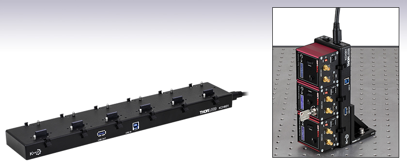
KCH301 Mounted Vertically with K-Cubes Installed (AP90 Bracket Not Included)
KCH601
Controller Hub


Please Wait
| Table 1.1 Specifications | ||
|---|---|---|
| Item # | KCH301 | KCH601 |
| K-/T-Cube Baysa | Three | Six |
| Housing Dimensions (without Mounting Brackets) | 193.5 mm x 70.0 mm x 24.0 mm (7.62" x 2.76" x 0.94") |
376.5 mm x 70.0 mm x 24.0 mm (14.82" x 2.76" x 0.94") |
| Weight | 0.3 kg | 0.5 kg |
| Input Power Requirements | 15 V, 10 A (Max) | |
| Output Power | +15 V, 6 A (Max) -15 V, 1 A (Max) +5 V, 5 A (Max) |
|
| USB Hub Circuit | Fully Compliant USB 2.0 Hub | |
| Finish | Black Anodized | |
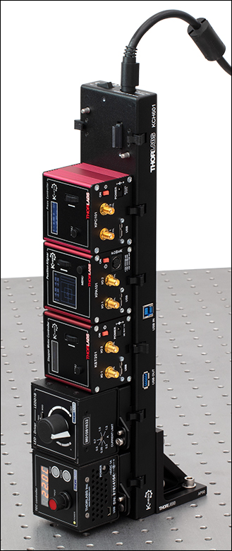
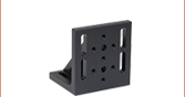
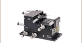
Click to Enlarge Figure 1.2 The controller hubs contain M6 taps on the bottom, allowing them to be mounted vertically using the AP90(/M) Right Angle Bracket (sold separately).
| K-Cube® Motion Control Modules |
|---|
| Brushed DC Servo Motor Controller |
| Brushless DC Servo Motor Controller |
| Fiber Alignment Controllers |
| Four-Channel Piezo Inertia Actuator Controller |
| PSD Auto Aligner |
| Single-Channel Piezo Controller and Strain Gauge Reader |
| Solenoid Controller |
| Stepper Motor Controller |
| Compact Light Source & Driver Modules |
| Laser Sources |
| Laser Diode Driver |
| LED Driver |
| Compact Temperature Control Module |
| Temperature Controller |
Features
- Enables Communication between K-Cubes®, T-Cubes™, and Host Control PC
- Supports up to Three (KCH301) or Six (KCH601) K-Cube or T-Cube Controllers
- Compact USB 2.0 Platform
- Horizontal or Vertical Mounting to Optical Tables
- Single USB Cable and Single Power Cable for all Connected K-Cubes and T-Cubes
- Second USB Port for Connecting Multiple Controller Hubs
- Fully RoHS Compliant
These USB Controller Hubs have been designed specifically with multiple K-Cube and T-Cube operation in mind. They simplify issues such as cable management, power supply routing, and multiple USB device communications. In addition, they make it possible to mount the electronic drivers on the optical table, next to all of the other mechanical components required to build an automated optomechanical application.
Each USB Controller Hub comprises a slim base-plate type carrier with electrical connections located on the upper surface. It contains a fully compliant USB 2.0 hub circuit and provides all communications and power distribution for up to three (KCH301) or six (KCH601) K-Cubes or T-Cubes, using only a single power connection. The hub draws a maximum current of 10 A; please verify that the cubes being used do not require a total current of more than 10 A. See Table 1.1 for output power specifications. The hubs are shipped complete with the power supply and horizontal mounting brackets.
The hub vastly reduces the number of USB and power cables required when operating multiple K-Cubes or T-Cubes. Furthermore, a USB output connector can be connected to the USB input on another unit, allowing multiple controller hubs to be connected together while still only using a single USB cable from the host control PC. As an added feature, the controller hub, when combined with devices that work in a closed loop such as the K-Cube Piezo Controller and Strain Gauge Reader paired with the K-Cube Position Sensing Detector, provides closed-loop control without the need for additional cabling.
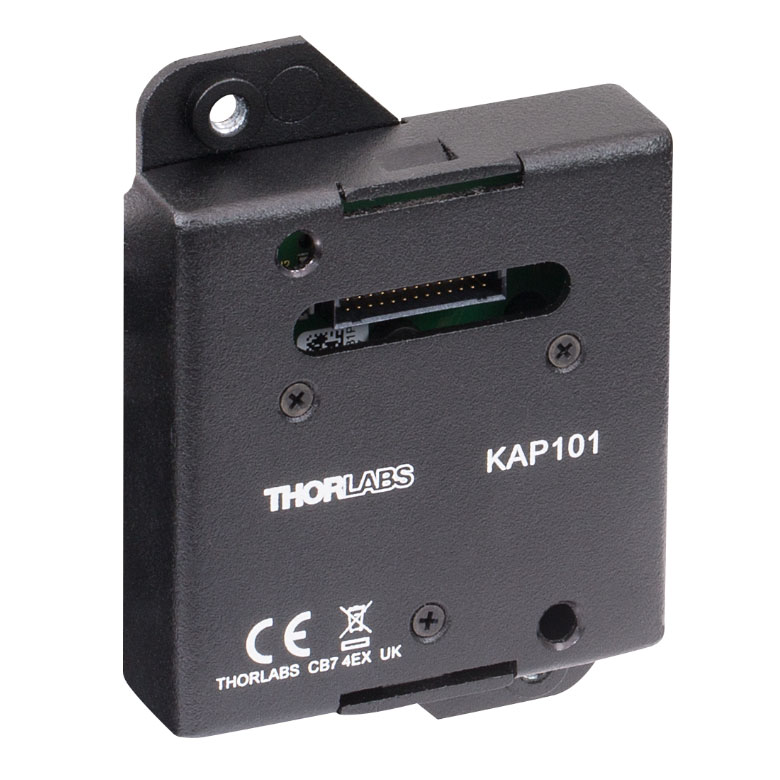
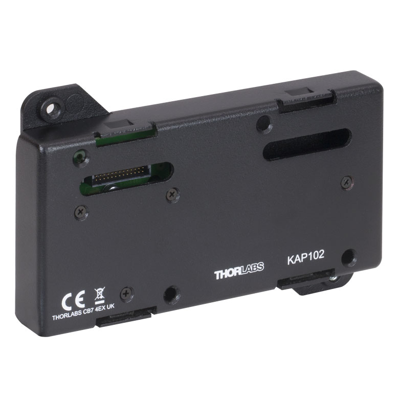
A KAP101 or KAP102 Adapter Plate (sold separately below) is required for each T-Cube to operate on the controller hub. The KAP101 is designed to adapt 60 mm wide T-Cubes to the hubs, while the KAP102 is designed to adapt 120 mm wide T-Cubes to the hubs.
Mounting Options
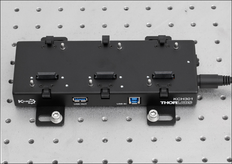
An array of mounting holes on the bottom of the USB Controller Hubs enables them to be mounted in multiple configurations to both imperial and metric tables. The hubs are shipped complete with mounting brackets that allow horizontal mounting; these brackets are compatible with both imperial and metric screws and allow the hub to be mounted flat on the optical table, much like the mounting plates of the individual cubes.
Alternatively, the AP90(/M) Right Angle Brackets, sold separately, can used to mount a hub vertically, thus saving space on the optical table. Two M6 cap screws (16 or 20 mm long) are required to attach the right angle bracket to the hub.
The hubs also have two (KCH301) or three (KCH601) magnets on the bottom to temporarily secure the hubs in place on the table.
Click to Enlarge
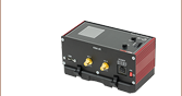
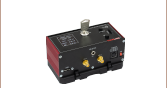
Figure 1.3 The KAP101 Adapter Plate (sold separately below) is required for mating 60 mm wide T-Cubes with KCH series hubs.
Click to Enlarge
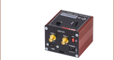
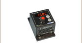
Figure 1.4 The KAP102 Adapter Plate (sold separately below) is required for mating 120 mm wide T-Cubes with KCH series hubs.
Click to Enlarge
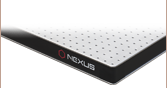
Figure 1.5 Each controller hub includes horizontal mounting brackets for securing the hub to an optical table or breadboard.
Power Connector
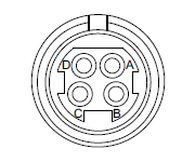
| Pin | Description | Minimum | Maximum | Max Operating Current |
|---|---|---|---|---|
| A | 15 V | 14 V | 16 V | 10 A |
| B | 15 V Return | - | - | - |
| C | 15 V Return | - | - | - |
| D | 15 V | 14 V | 16 V | 10 A |
USB OUT

This port can be connected to the USB IN on another Hub or other USB device, allowing multiple Controller Hubs to be connected together, thereby requiring only a single USB cable from the host control PC.
USB IN
Provides communication to the host controller PC.
Software
Kinesis Version 1.14.54
XA Version 1.2.7
The Kinesis and XA Software Packages, which include a GUI for control of Thorlabs' motion controllers.
Also Available:
- Communications Protocol
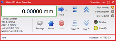
Figure 789A Kinesis GUI Screen
Thorlabs offers two platforms to drive our wide range of motion controllers: our XA software package and our Kinesis software package, which is being phased out. The Kinesis software supports most of Thorlabs' motion control products. The XA software is an improved platform for developers that currently supports some of our most popular motion control products (see the full list of supported products here). The software is undergoing continuous, intensive development and will eventually add support for our entire line of motion control products. The XA software application will be fully supported through the year 2040.
Kinesis Motion Control Software
The Kinesis software features .NET controls which can be used by 3rd party developers working in the latest C#, Visual Basic, LabVIEW™, or any .NET compatible languages to create custom applications. Low-level DLL libraries are included for applications not expected to use the .NET framework. A Central Sequence Manager supports integration and synchronization of all Thorlabs motion control hardware.
By providing a common software platform, Thorlabs has ensured that users can easily mix and match any of the Kinesis controllers in a single application, while only having to learn a single set of software tools. In this way, it is perfectly feasible to combine any of the controllers from single-axis to multi-axis systems and control all from a single, PC-based unified software interface.
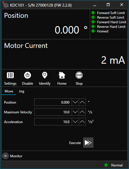
Click to Enlarge
Figure 789B XA GUI for KDC101 Brushed DC Servo Controller
The software package allows two methods of usage: graphical user interface (GUI) utilities for direct interaction with and control of the controllers out of the box, and a set of programming interfaces that allow custom-integrated positioning and alignment solutions to be easily programmed in the development language of choice.
XA Motion Control Software: Improved Platform for Developers
Designed from the ground up to be straightforward to understand, XA provides a thread-safe and language-paradigm-agnostic set of application programming interfaces in C, C++, and C#/.NET with language wrappers available to allow for easy integration into your native, .NET language, Python, or LabVIEW applications. This enables the same functionality as mentioned for the Kinesis software development kit (SDK) while providing a more streamlined toolkit for developers. Coupled with the included developer guides and code examples in the SDK, this software is tailored toward users interested in creating complex, customized applications and interfaces. Full API documentation is provided for the native C library, and the .NET wrapper documentation is currently under development. Please contact Tech Support for more details on using the .NET wrapper.
XA also features a comparable GUI to Kinesis while adding improvements to the user experience, like the ability to save device states and a more consistent interface across devices of different types. In addition, further improvements are planned as XA will be fully supported through the year 2040, whereas the Kinesis software is being phased out. The current version of the XA software can only drive select Thorlabs motion controllers. However, the software is undergoing continuous, intensive development and will eventually add support for our entire line of motion control products. Information on software compatibility can be found in the XA User Guide, and additional details about the software, including a list of compatible devices, can be found here.
Thorlabs' Kinesis software features new .NET controls which can be used by third-party developers working in the latest C#, Visual Basic, LabVIEW™, or any .NET compatible languages to create custom applications.
C#
This programming language is designed to allow multiple programming paradigms, or languages, to be used, thus allowing for complex problems to be solved in an easy or efficient manner. It encompasses typing, imperative, declarative, functional, generic, object-oriented, and component-oriented programming. By providing functionality with this common software platform, Thorlabs has ensured that users can easily mix and match any of the Kinesis controllers in a single application, while only having to learn a single set of software tools. In this way, it is perfectly feasible to combine any of the controllers from the low-powered, single-axis to the high-powered, multi-axis systems and control all from a single, PC-based unified software interface.
The Kinesis System Software allows two methods of usage: graphical user interface (GUI) utilities for direct interaction and control of the controllers 'out of the box', and a set of programming interfaces that allow custom-integrated positioning and alignment solutions to be easily programmed in the development language of choice.
For a collection of example projects that can be compiled and run to demonstrate the different ways in which developers can build on the Kinesis motion control libraries, click on the links below. Please note that a separate integrated development environment (IDE) (e.g., Microsoft Visual Studio) will be required to execute the Quick Start examples. The C# example projects can be executed using the included .NET controls in the Kinesis software package (see the Kinesis Software tab for details).
 |
Click Here for the Kinesis with C# Quick Start Guide Click Here for C# Example Projects Click Here for Quick Start Device Control Examples |
|
LabVIEW
LabVIEW can be used to communicate with any Kinesis-based controller via .NET controls. In LabVIEW, you build a user interface, known as a front panel, with a set of tools and objects and then add code using graphical representations of functions to control the front panel objects. The LabVIEW tutorial, provided below, provides some information on using the .NET controls to create control GUIs for Kinesis-driven devices within LabVIEW. It includes an overview with basic information about using controllers in LabVIEW and explains the setup procedure that needs to be completed before using a LabVIEW GUI to operate a device.
 |
Click Here to View the LabVIEW Guide Click Here to View the Kinesis with LabVIEW Overview Page |
|
| Posted Comments: | |
Lai KunKun
(posted 2025-05-21 11:01:25.963) After updating the KDC101 firmware to version 2.2.6, there is a discrepancy between the motor displacement commanded by the APT User control software and the actual displacement. For example, when the APT User commands the motor to move 0.1mm, the actual movement is 0.093mm. Are there any solutions to this issue? Can reverting the KDC101 hardware version resolve the problem? Looking forward to your reply.Thank you. cstroud
(posted 2025-05-29 11:32:38.0) Thanks for reaching out, I'm sorry that you're having issues with your controller. I will contact you directly to help troubleshoot this issue. user
(posted 2025-05-14 16:04:35.157) I have purchased the KCH601 along with a KPA101 position aligner, a quadrant PDQ30C quadrant photodiode and a MDT693B. Can you provide me with example codes in python, other than the typical provided at the ThorLabs GITHUB, because i have a lot of issues due to voltage restriction of the MDT693 piezocontroller and the -10V to10V output currents of the KPA101 aligner.
Thank you dnewnham
(posted 2025-05-28 09:48:15.0) Thank you for your inquiry, GitHub is the only place where we post our python examples but I will reach out to you directly to assist with this particular query. Young Soo Yu
(posted 2024-11-05 11:10:48.413) Hello, I'm Young-Soo Yu from KAIST. I am using KCH601 for several brushless motor driver KDB101. But I managed to find some malfunction from the KCH601.
After turning off the KCH601 before a blackout, two of the ports of the KCH601 shows errors. More precisely, when using a Kinesis software to control the K cubes, I couldn't get connection to the ports that are not working.
I found out that there were USB recognition errors found at windows device manager for the two malfunctioning ports.
We had a same problem with KCH601 last year and got an exchange, but got the same problem again.
Can you give me an adivce? dnewnham
(posted 2024-11-07 06:05:50.0) Thank you for your inquiry I will reach out to you directly to help troubleshoot this for you E BIVER
(posted 2024-07-23 12:46:16.57) What are the 4-pin power connector type and the power supply part number for the KCH301? I need to make an extension cable for it.
Is it possible to use another 15 V power supply? cstroud
(posted 2024-07-26 10:05:15.0) Thanks for reaching out. The 4-pin power connector type is the Kycon KPPX-4P. I will contact you directly to discuss extension cables. Jay P
(posted 2023-10-31 15:07:39.67) We are using this product for powering 6 T-cube LED drivers (LEDD1B).
My question is if this product can support remote control of LED intensities in each slot via USB connection to alter manual control using the knobs at each driver. The technical details in the product information describes motion control examples. If there is any example software or documentation which is applicable to LEDD1B, let us find and use that solution.
Thank you in advance. do'neill
(posted 2023-11-10 10:50:26.0) Response from Daniel at Thorlabs. The LEDD1B has no remote control functionality even using the KCH601 hubs. They can only be controlled by the knobs or the modulation inputs on the back of the cubes and only use the Hubs for power not USB control. Ralph Malein
(posted 2022-08-02 14:02:05.593) I'm having a similar problem to others below: I have 3 K-cubes controlling an xyz stage that I would like to use with the KCH601 but when docked to the hub, while they are powered on and can be controlled manually, Kinesis does not recognise them. cwright
(posted 2022-08-03 04:28:52.0) Response from Charles at Thorlabs: Thank you for your query. Often this is because the switch on the hub itself has been forgotten but it can also be an issue with the hub. Technical support will reach out to you to help troubleshoot this. heloise Bourgeois
(posted 2022-06-03 14:44:53.443) hello,
I have just received a KCH601 with KDC101 cubes. The cubes are recognized with direct USB connections and Kinesis +Windows 7 64 bits? but none of them is recognized when attached to the hub (which seems to be not working except for the power supply).
I am DISAPPOINTED !
Please give me some information. DJayasuriya
(posted 2022-06-07 10:08:49.0) Thank you for your inquiry. We have got in touch with you directly to resolve the issue. Usually if the cube is directly connected to your computer than through the hub this issue would show up. Jisoo Kyoung
(posted 2022-03-08 14:50:16.423) Dear thorlabs,
Hello, I am Jisoo Kyoung from Dankook university in Korea.
I am interested in your KCH301.
I am using a single KDC101 (K-Cube Brushed DC Servo Motor Controller) and control it by Python code you provided.
My controller is directly connected to my PC by USB cable.
Now, I am planning to control two KDC101 controllers by using KCH301.
If I use KCH301, then only single USB connection to PC is available even though I have two contollers.
Then, is it possible to independently control each KDC101 though a single connection?
My goal is to control two KDC101 using Python code.
It would be good if I can use KCH301 with Python code to make compact set up.
But I'm not sure if I can control the KCH301 with Python.
Thanks. DJayasuriya
(posted 2022-03-09 03:37:52.0) Thank you for your inquiry. Using the KCH301 although there is only one USB cable you would be able to control multiple K-cubes using Python. We will gt in touch with you directly with some example code. Aurelien David
(posted 2021-10-12 19:23:19.78) I am having issues with this hub and a KDC101 controller.
I have two KDC101 controllers, both purchased at the same time 2 years ago. Both work fine when connected directly to the computer (without the hub).
When I connect the cubes through the hub: one of them still works fine; but the other one is not detected in Kinesis (so, it cannot be loaded). The cube is powered normally by the hub (the display is on). I tried several positions on the hub - this cube is never detected. cwright
(posted 2021-10-13 03:58:40.0) Response from Charles at Thorlabs: Thank you for contacting us. It could be there is an issue with the connector on the underside of the cube. Your local technical support team will reach out to you to help with troubleshooting. Tsai hung lu
(posted 2021-10-13 17:26:50.937) When we connect Z812 KDC101 & KCH301, we can control Z812 by KDC101
But when we try to use computer control Z812 by USB from KCH301 to PC, it can't find the USB device.
How could we solve this problem DJayasuriya
(posted 2021-10-14 03:50:04.0) Thank you for your inquiry. we will get in touch with you directly to resolve your issue. arie faitelson
(posted 2021-01-26 23:29:31.207) brick connected through USB.
Kcube controllers are not recognized by kinesis.
the controllers work directly connected. cwright
(posted 2021-01-27 10:04:09.0) Response from Charles at Thorlabs: Thank you for contacting us. I am sorry to hear you are having this trouble. Technical support will reach out to you directly to assist with troubleshooting. In these cases we would recommend ensuring that the device is not connected through a hub but rather directly to the computer and that multiple USB ports have been tried. It is also worth ensuring that the power supply is working adequately. Len Ness
(posted 2019-05-30 16:12:00.473) I am using the KCH301 with 2 T-cubs and 1 KDC101. When in trigger mode the T-cubes won't trigger. If I take them off of the KCH301 and power them separately they trigger fine. How can I correct this? rmiron
(posted 2019-06-04 10:08:28.0) Response for Radu at Thorlabs: This could be happening for a few different reasons. I will contact you directly in order to offer troubleshooting instructions. evan.meyer.scott
(posted 2019-02-20 09:11:32.867) Is it safe to use the main switch on the KCH601 to power down all connected K-Cubes? Or should each K-Cube be switched off individually first? rmiron
(posted 2019-02-21 05:20:54.0) Response from Radu at Thorlabs: Hello Evan. We advise you to switch off each cube individually before switching off the hub (and viceversa when switching on). That is the safest sequence because it minimises any transient effects. With that being said, if that is not an option for you, we think the risk of failure due to your planed course of action is low because the hub and its power supply were also designed to deal with transience. fabrice.onofri
(posted 2018-05-18 13:40:36.953) I have just received a KCH601 with KDC101 cubes.
The cubes are recognized with direct USB connections and Kinesis +Windows 7 64 bits, but only but none of them is recognized when attached to the hub (which seems to be not working except for the power supply). Please help. rmiron
(posted 2018-05-24 04:08:59.0) Response from Radu at Thorlabs: I am sorry to read that. All of the hub's ports are inspected before packaging so this is a surprising occurrence. With that being said, it is possible that a conductive element was dislodged during shipping, creating an open circuit. We will send you a replacement straight away. We will also collect the hub you received in order to inspect it and learn how such issues can be prevented in the future. I will contact you directly to discuss the matter further. james.david.good
(posted 2017-09-21 16:29:52.71) I have a two KDC101 cubes with sequential serial numbers (xxx837 & xxx839), both are recognized in Windows 7 with direct USB connections but only one is recognized when attached to the hub. AManickavasagam
(posted 2017-09-25 11:21:53.0) Response from Arunthathi at Thorlabs:
Thank you for your comment.
I am sorry that you have difficulties here. I will be in direct contact with you to troubleshoot this issue. james.ivory
(posted 2017-04-27 15:18:47.937) I have a KCH601 with 3 cubes attached. When I am trying to identify hardware in the firmware update utility, the only thing that is found is a single cube. The two other cubes are powered and work manually, but will not be recognised by the PC. Please advise. bwood
(posted 2017-05-02 09:43:54.0) Response from Ben at Thorlabs: I am sorry to hear about your difficulties here. I will be in contact with you directly, to troubleshoot this issue further. avize
(posted 2017-03-16 01:24:16.33) I recently purchased the KCH301.
The computer identifies a USB 2.0 MTT hub, but the Kinesis software does not recognize any device.
Please advise. bwood
(posted 2017-03-16 07:49:20.0) Response from Ben at Thorlabs: I am sorry to hear about your issues here. I will be in contact directly to help troubleshoot the problem. However, in general a good way to assess the communications between Kinesis and any given controller is the Firmware Update Utility included with Kinesis. If the controller appears, then USB communications have been established with the computer, and if the drop down menu of the device can be opened, this means the controller and Kinesis are communicating. user
(posted 2016-10-01 17:12:04.317) What devices can be used by this "Kinesis" software? Is there a webpage that lists all compatible devices? bwood
(posted 2016-10-03 03:50:31.0) Response from Ben at Thorlabs: Thank you for your question. The Kinesis software is designed to be used with our range of motion control controllers, and certain complementary devices. More specifically, it is compatible with our K-cube, T-cube, Benchtop (for example the BSC201) and rack controllers. It is also compatible with certain devices with integrated controllers, including the LTS series stages, the K10CR1 and the MLJ050. The most notable exceptions to this are the LEDD1B, stages using Elliptec™ motors and the MDT series controllers. Usually, the compatible software for a given device can be found under the "Software" tab on its webpage. If you need further advice on a particular device, please contact your local technical support office, who will be happy to assist you. user
(posted 2014-10-14 15:09:43.663) I am using C# and an FTDI driver to communicate with a TQD001 (position 1) and TPZ001 (position 2) mounted on a TCH002 hub. When I send the IDENTIFY command (05 00 00 00 21 01) the TPZ001 LED's flash. It does not seem to matter which destination I specify, I can only get TPZ001 to flash. I have tried 0x20, 0x21, 0x22, 0x50, etc for the destination. The APT User software is able to flash both device's LED's. Thank-you for any help you can provide. bhallewell
(posted 2014-10-30 10:15:10.0) Response from Ben at Thorlabs: Thank you for your question here. It is important to view the TCH002 as a USB hub, containing a serial port for each mounted cube & not as a single USB device. With this in mind, it is not possible to ‘Identify’ the TQD001 if you are altering the destination byte through a single serial port in your program. You would instead be required to tailor your program to send the 23, 02, 00, 00, 50*, 01 Identify Command through each serial port corresponding to a designated T-cube controller. This could perhaps be done by establishing a VCP/Hyperlink terminal for each T-cube device.
*‘50’ being the destination byte corresponding to ‘Generic USB Device) jlow
(posted 2012-10-25 11:33:00.0) Response from Jeremy at Thorlabs: The 4-pin connector type on the TCH002 is the Farnell 1007205. zimm
(posted 2012-10-21 18:12:54.09) What is the 4-pin power connector & part number for the power cable on the TCH002? I need to make an extension cable for it. |