 Products Home
NIR Transmission Gratings
- Gratings Designed for Optimum Use in the NIR
- Two Groove Angles Available: 24.8° and 31.7°
- Two Sizes Available: 25 mm x 25 mm and 50 mm x 50 mm
GTI50-03A
(50 mm x 50 mm)
GTI25-03A
(25 mm x 25 mm)


Please Wait
| Selection Guide | |
|---|---|
| Transmission Gratings | |
| Ruled | UV |
| Visible | |
| Near IR | |
| Volume Phase Holographic |
Visible |
| Near IR | |
| Reflective Gratings | |
| Ruled | UV |
| Visible | |
| Near IR | |
| Mid IR | |
| Holographic | |
| Echelle | |
| Common Specifications | |
|---|---|
| Substrate Material | Schott B270 |
| Thickness | 3 mm Nominal |
| Dimensional Tolerances | ±0.5 mm |
| Thickness Tolerance | ±0.5 mm |
Features
- Designed for Optimum Performance in the Near Infrared
- Ideal for Fixed Grating Applications
- Schott B270 Substrate
- Custom Sizes Available Upon Request
Thorlabs' Near Infrared Transmission Gratings are designed for the 500 nm to 1.8 μm range. Due to their basic simplicity, transmission gratings are beneficial for use in fixed grating applications, such as spectrographs. The incident light is dispersed on the opposite side of the grating at a fixed angle. Transmission gratings provide low alignment sensitivity, which minimizes alignment errors. These grooved transmission gratings were designed for optimum performance in the near infrared, offering different levels of dispersion. In most cases, the efficiency of these gratings is comparable to that of reflection gratings such as Ruled Gratings or Holographic Gratings when used in the same wavelength range.
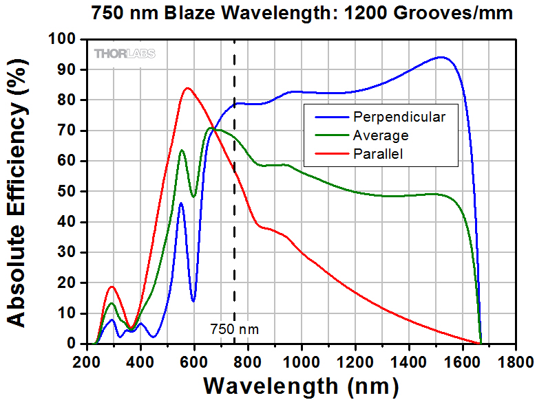
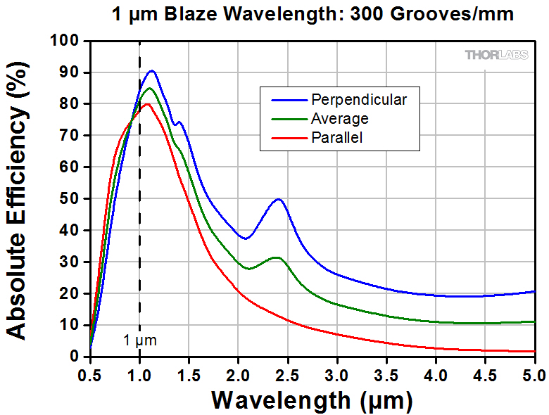
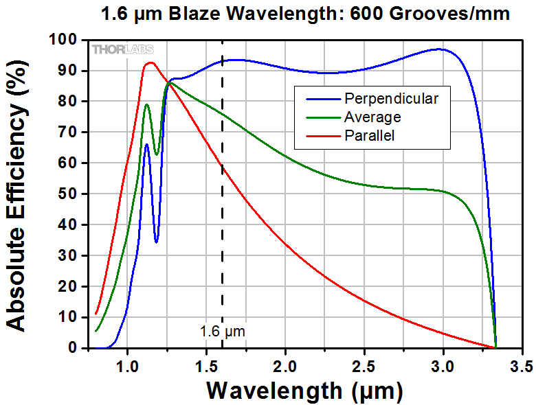
By necessity, transmission gratings require relatively coarse groove spacings to maintain high efficiency. As the diffraction angles increase with the finer spacings, the refractive properties of the substrate materials used limit the transmission at the higher wavelengths and performance drops off. The grating dispersion characteristics, however, lend themselves to compact systems utilizing small detector arrays. The gratings are also relatively polarization insensitive. Our NIR transmission gratings are offered in two different sizes, with a choice of two groove angles. Please see Figures 1.1 and 1.3 for performance characteristics.
Please see the Gratings Guide tab to choose the right grating for your application.
Mounts and Adapters
Thorlabs' gratings can be mounted directly into the KM100C Right-Handed or KM100CL Left-Handed Kinematic Rectangular Optic Mount for precise and stable mounting and alignment.
Warning:
Optical gratings can be easily damaged by moisture, fingerprints, aerosols, or the slightest contact with any abrasive material. Gratings should only be handled when necessary and always held by the sides. Latex gloves or a similar protective covering should be worn to prevent oil from fingers from reaching the grating surface. No attempt should be made to clean a grating other than blowing off dust with clean, dry air or nitrogen. Solvents will likely damage the grating's surface.
Thorlabs uses a clean room facility for assembly of gratings into mechanical setups. If your application requires integrating the grating into a sub-assembly or a setup, please contact us to learn more about our assembly capabilities.

Click to Enlarge
Click Here for Raw Data
Figure 1.1 NIR transmission grating performance at 24.8° blaze angle. The absolute efficiency plotted here includes Fresnel reflections.
Click to Enlarge
Click Here for Raw Data
Figure 1.2 NIR transmission grating performance at 31.7° blaze angle. The absolute efficiency plotted here includes Fresnel reflections.
Click to Enlarge
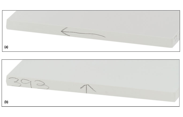
Figure 1.3 On one edge of the grating, (a), an arrow parallel to the grating's surface indicates the blaze direction (as defined in the Gratings Tutorial tab). On the opposite edge of the grating, (b), an arrow perpendicular to the grating's surface indicates the transmission direction.
Diffraction Gratings Tutorial
- Introduction
- Blazed (Ruled) Gratings
- Volume Phase Holographic Transmission Gratings
- Holographic Reflective Gratings
Introduction
Diffraction gratings, either transmissive or reflective, can separate different wavelengths of light using a repetitive structure embedded within the grating. The structure affects the amplitude and/or phase of the incident wave, causing interference in the output wave. In the transmissive case, the repetitive structure can be thought of as many tightly spaced, thin slits. Solving for the irradiance as a function wavelength and position of this multi-slit situation, we get a general expression that can be applied to all diffractive gratings when ![]() = 0°,
= 0°,
known as the grating equation. The equation states that a diffraction grating with spacing ![]() will deflect light at discrete angles (
will deflect light at discrete angles (![]() ), dependent upon the value
), dependent upon the value ![]() λ, where
λ, where ![]() is the order of principal maxima. The diffracted angle,
is the order of principal maxima. The diffracted angle, ![]() , is the output angle as measured from the surface normal of the diffraction grating. It is easily observed from Equation 1 that for a given order
, is the output angle as measured from the surface normal of the diffraction grating. It is easily observed from Equation 1 that for a given order ![]() , different wavelengths of light will exit the grating at different angles. For white light sources, this corresponds to a continuous, angle-dependent spectrum.
, different wavelengths of light will exit the grating at different angles. For white light sources, this corresponds to a continuous, angle-dependent spectrum.
Figure 48A Transmission Grating
Transmission Gratings
One popular style of grating is the transmission grating. The sample diffraction grating with surfaces grooves shown in Figure 48A is created by scratching or etching a transparent substrate with a repetitive series of narrow-width grooves separated by distance ![]() . This creates areas where light can scatter.
. This creates areas where light can scatter.
The incident light impinges on the grating at an angle ![]() , as measured from the surface normal. The light of order
, as measured from the surface normal. The light of order ![]() exiting the grating leaves at an angle of
exiting the grating leaves at an angle of ![]() , relative to the surface normal. Utilizing some geometric conversions and the general grating expression (Equation 1) an expression for the transmissive diffraction grating can be found:
, relative to the surface normal. Utilizing some geometric conversions and the general grating expression (Equation 1) an expression for the transmissive diffraction grating can be found:

where both ![]() and
and ![]() are positive if the incident and diffracted beams are on opposite sides of the grating surface normal, as illustrated in the example in Figure 48A. If they are on the same side of the grating normal,
are positive if the incident and diffracted beams are on opposite sides of the grating surface normal, as illustrated in the example in Figure 48A. If they are on the same side of the grating normal, ![]() must then be considered negative.
must then be considered negative.
Figure 48B Reflective Grating
Reflective Gratings
Another very common diffractive optic is the reflective grating. A reflective grating is traditionally made by depositing a metallic coating on an optic and ruling parallel grooves in the surface. Reflective gratings can also be made of epoxy and/or plastic imprints from a master copy. In all cases, light is reflected off of the ruled surface at different angles corresponding to different orders and wavelengths. An example of a reflective grating is shown in Figure 48B. Using a similar geometric setup as above, the grating equation for reflective gratings can be found:

where ![]() is positive and
is positive and ![]() is negative if the incident and diffracted beams are on opposite sides of the grating surface normal, as illustrated in the example in Figure 48B. If the beams are on the same side of the grating normal, then both angles are considered positive.
is negative if the incident and diffracted beams are on opposite sides of the grating surface normal, as illustrated in the example in Figure 48B. If the beams are on the same side of the grating normal, then both angles are considered positive.
Both the reflective and transmission gratings suffer from the fact that the zeroth order mode contains no diffraction pattern and appears as a surface reflection or transmission, respectively. Solving Equation 2 for this condition, ![]() =
= ![]() , we find the only solution to be
, we find the only solution to be ![]() =0, independent of wavelength or diffraction grating spacing. At this condition, no wavelength-dependent information can be obtained, and all the light is lost to surface reflection or transmission.
=0, independent of wavelength or diffraction grating spacing. At this condition, no wavelength-dependent information can be obtained, and all the light is lost to surface reflection or transmission.
This issue can be resolved by creating a repeating surface pattern, which produces a different surface reflection geometry. Diffraction gratings of this type are commonly referred to as blazed (or ruled) gratings. More information about this can be found in the section below.
Blazed (Ruled) Gratings
Figure 48D Blazed Grating, 0th Order Reflection
Figure 48C Blazed Grating Geometry
The blazed grating, also known as the echelette grating, is a specific form of reflective or transmission diffraction grating designed to produce the maximum grating efficiency in a specific diffraction order. This means that the majority of the optical power will be in the designed diffraction order while minimizing power lost to other orders (particularly the zeroth). Due to this design, a blazed grating operates at a specific wavelength, known as the blaze wavelength.
The blaze wavelength is one of the three main characteristics of the blazed grating. The other two, shown in Figure 48C, are ![]() , the groove or facet spacing, and
, the groove or facet spacing, and ![]() , the blaze angle. The blaze angle
, the blaze angle. The blaze angle ![]() is the angle between the surface structure and the surface parallel. It is also the angle between the surface normal and the facet normal. Note that Figure 48C also defines the direction of the "blaze arrow"; this arrow is visibly marked on one edge of all Thorlabs' blazed transmission gratings.
is the angle between the surface structure and the surface parallel. It is also the angle between the surface normal and the facet normal. Note that Figure 48C also defines the direction of the "blaze arrow"; this arrow is visibly marked on one edge of all Thorlabs' blazed transmission gratings.
The blazed grating features geometries similar to the transmission and reflection gratings discussed thus far; the incident angle (![]() ) and
) and ![]() th order reflection angles (
th order reflection angles (![]() ) are determined from the surface normal of the grating. However, the significant difference is the specular reflection geometry is dependent on the blaze angle,
) are determined from the surface normal of the grating. However, the significant difference is the specular reflection geometry is dependent on the blaze angle, ![]() , and NOT the grating surface normal. This results in the ability to change the diffraction efficiency by only changing the blaze angle of the diffraction grating.
, and NOT the grating surface normal. This results in the ability to change the diffraction efficiency by only changing the blaze angle of the diffraction grating.
The 0th order reflection from a blazed grating is shown in Figure 48D. The incident light at angle ![]() is reflected at
is reflected at ![]() for
for ![]() = 0. From Equation 3, the only solution is
= 0. From Equation 3, the only solution is ![]() = –
= –![]() . This is analogous to specular reflection from a flat surface.
. This is analogous to specular reflection from a flat surface.
Figure 48F Blazed Grating, Incident Light Normal to Grating Surface
Figure 48E Blazed Grating, Specular Reflection from Facet
The specular reflection from the blazed grating is different from the flat surface due to the surface structure, as shown in Figure 48E. The specular reflection, ![]() , from a blazed grating occurs at the blaze angle geometry. This angle is defined as being negative if it is on the same side of the grating surface normal as
, from a blazed grating occurs at the blaze angle geometry. This angle is defined as being negative if it is on the same side of the grating surface normal as ![]() . Performing some simple geometric conversions, one finds that
. Performing some simple geometric conversions, one finds that

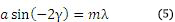
Figure 48F illustrates the specific case where ![]() = 0°, hence the incident light beam is perpendicular to the grating surface. In this case, the 0th order reflection also lies at 0°. Utilizing Eqs. 3 and 4, we can find the grating equation at twice the blaze angle:
= 0°, hence the incident light beam is perpendicular to the grating surface. In this case, the 0th order reflection also lies at 0°. Utilizing Eqs. 3 and 4, we can find the grating equation at twice the blaze angle:
Littrow Configuration for Reflective Gratings
The Littrow configuration refers to a specific geometry for blazed gratings and plays an important role in monochromators and spectrometers. It is the angle ![]() at which the grating efficiency is the highest. In this configuration, the angle of incidence of the incoming and diffracted light are the same,
at which the grating efficiency is the highest. In this configuration, the angle of incidence of the incoming and diffracted light are the same, ![]() =
= ![]() , and
, and ![]() > 0 so
> 0 so
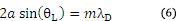
Figure 48G Littrow Configuration
The Littrow configuration angle, ![]() , is dependent on the most intense order (
, is dependent on the most intense order (![]() = 1), the design wavelength,
= 1), the design wavelength, ![]() , and the grating spacing
, and the grating spacing ![]() . It is easily shown that the Littrow configuration angle,
. It is easily shown that the Littrow configuration angle, ![]() , is equal to the blaze angle,
, is equal to the blaze angle, ![]() , at the design wavelength. The Littrow / blaze angles for all Thorlabs' Blazed Gratings can be found in the grating specs tables.
, at the design wavelength. The Littrow / blaze angles for all Thorlabs' Blazed Gratings can be found in the grating specs tables.

It is easily observed that the wavelength dependent angular separation increases as the diffracted order increases for light of normal incidence (for ![]() = 0°,
= 0°, ![]() increases as
increases as ![]() increases). There are two main drawbacks for using a higher order diffraction pattern over a low order one: (1) a decrease in efficiency at higher orders and (2) a decrease in the free spectral range,
increases). There are two main drawbacks for using a higher order diffraction pattern over a low order one: (1) a decrease in efficiency at higher orders and (2) a decrease in the free spectral range, ![]() , defined as:
, defined as:

where ![]() is the central wavelength, and
is the central wavelength, and ![]() is the order.
is the order.
The first issue with using higher order diffraction patterns is solved by using an Echelle grating, which is a special type of ruled diffraction grating with an extremely high blaze angle and relatively low groove density. The high blaze angle is well suited for concentrating the energy in the higher order diffraction modes. The second issue is solved by using another optical element: grating, dispersive prism, or other dispersive optic, to sort the wavelengths/orders after the Echelle grating.
Figure 48H Volume Phase Holographic Grating
Volume Phase Holographic Transmission Gratings
Unlike traditional gratings, volume phase holographic (VPH) gratings do not have surface grooves. Instead, VPH gratings consist of a dichromated gelatin (DCG) film between two glass substrates. These VPH gratings are designed to reduce the periodic errors that can occur in blazed gratings. Surface gratings with high groove density also have an issue with polarization dependent loss. These unique transmission gratings deliver high first-order diffraction peak efficiency, low polarization dependence, and uniform performance over broad bandwidths.
The desired grating pattern is comprised of a repetitive series of lines separated by distance ![]() . The fringe planes for transmission gratings are perpendicular to the plane of the plate as seen in Figure 48H, allowing any frequency of light to pass through the plate. Diffraction occurs as incoming light crosses through the DCG film. Therefore, the three major factors that determine performance are film thickness, bulk index (the average index of refraction between Bragg planes), and index modulation (the difference of index of refraction between the Bragg planes). The incident light enters the grating at an angle of
. The fringe planes for transmission gratings are perpendicular to the plane of the plate as seen in Figure 48H, allowing any frequency of light to pass through the plate. Diffraction occurs as incoming light crosses through the DCG film. Therefore, the three major factors that determine performance are film thickness, bulk index (the average index of refraction between Bragg planes), and index modulation (the difference of index of refraction between the Bragg planes). The incident light enters the grating at an angle of ![]() , as measured from the surface normal. The light of order
, as measured from the surface normal. The light of order ![]() exiting the grating leaves at an angle of
exiting the grating leaves at an angle of ![]() , relative to the surface normal. The grating expression mentioned above can be used to calculate diffraction angles for volume phase holographic gratings since dispersion is based on the line density. The quality of the grating is determined by the fringe contrast, with a poor fringe contrast resulting in low efficiency or no grating at all.
, relative to the surface normal. The grating expression mentioned above can be used to calculate diffraction angles for volume phase holographic gratings since dispersion is based on the line density. The quality of the grating is determined by the fringe contrast, with a poor fringe contrast resulting in low efficiency or no grating at all.
The DCG film is taken through multiple quality control steps to ensure it performs up to standard and then cut into the desired size. The film is sealed between two glass covers to prevent degradation of the material. Since the DCG film is contained between two glass substrates, VPH gratings have high durability and long lifetimes, as well as easy maintenance compared to other gratings that can be easily damaged.

Figure 48J Holographic Grating
Holographic Surface Reflective Gratings
While blazed gratings offer extremely high efficiencies at the design wavelength, they suffer from periodic errors, such as ghosting, and relatively high amounts of scattered light, which could negatively affect sensitive measurements. Holographic gratings are designed specially to reduce or eliminate these errors. The drawback of holographic gratings compared to blazed gratings is reduced efficiency.
Holographic gratings are made from master gratings by similar processes to the ruled grating. The master holographic gratings are typically made by exposing photosensitive material to two interfering laser beams. The interference pattern is exposed in a periodic pattern on the surface, which can then be physically or chemically treated to expose a sinusoidal surface pattern. An example of a holographic grating is shown in Figure 48J.
Please note that dispersion is based solely on the number of grooves per mm and not the shape of the grooves. Hence, the same grating equation can be used to calculate angles for holographic as well as ruled blazed gratings.
| Posted Comments: | |
Chris Rodgers
(posted 2025-11-22 14:55:43.247) Is it possible to get a csv file with the transmission raw data for the grating with uncertainties? Weiyu Lee
(posted 2025-01-05 21:53:38.06) How to know the incident angle according to the groove angle? let's say it is at 520nm EGies
(posted 2025-01-06 05:30:27.0) Thank you for contacting Thorlabs. The diffraction angle theta_m can be determined based on incident angle theta_i using the equation a[sin(theta_m) - sin(theta_i)] = m*lambda, where a is the groove spacing, m is the diffraction order, and lambda is the operating wavelength. The blaze/groove angle for these transmission gratings does not change the incident or diffraction angle, only the efficiency vs wavelength. That said, the standard angle of incidence for a transmission grating is typically 0 degrees. I have reached out to you directly regarding your specific application. Vahideh Farzam Rad
(posted 2024-06-23 23:46:23.257) Hello,
Since we need the 1746 grooves/mm grating in the NIR range, can we order this kind of grating?
thanks cdolbashian
(posted 2024-07-01 01:24:01.0) Thank you for reaching out to us with this inquiry. Unfortunately at this time, we are unable to produce something with this specific groove spacing. I have reached out to you directly to discuss your application and possible alternatives. Xichen Hu
(posted 2023-09-11 15:23:04.31) We would like to know the damage threshold of GTI50-03 for ultrafast (30fs) laser. It would be nice if you could provide damage thresholds for all your gratings. Thank you. cdolbashian
(posted 2023-09-25 08:49:40.0) Thank you for reaching out to us with this request. This is indeed a good idea moving forward. I have contacted you with the information we currently have regarding the pulse damage threshold for these components. 月 石
(posted 2022-09-12 12:03:14.51) 请问贵司透射型闪耀光栅的结构单元是三角形还是锯齿形?为什么实验中会出现800nm正负一级衍射角不同的情况? cdolbashian
(posted 2022-09-16 09:41:12.0) Thank you for reaching out to us with this inquiry! Our gratings are sawtooth style blazed gratings. I have reached out to you regarding you inquiry surrounding the 800nm experiment for clarification. 永威 吴
(posted 2022-09-05 21:57:57.403) Whether the positive and negative first-order light and the zero order light diffracted by the transmission grating have the same light intensity cdolbashian
(posted 2022-09-19 10:35:29.0) Thank you for reaching out to us with this inquiry! We do share some guiding equations regarding where the light will fall spatially, but for the relative intensities of light in different optical configurations, a bit more algebra is required. I have emailed you with some explicit and helpful sources, which may assist you with your particular inquiry. Jhon pabon
(posted 2021-11-12 11:21:26.35) There is a problem with the Auto CAD PDF YLohia
(posted 2021-11-12 04:52:29.0) Thank you for contacting Thorlabs. I have reached out to you directly to gather more information on the issue, as the AutoCAD pdf is loading correctly for us. user
(posted 2020-10-26 09:01:42.303) We are designing a Prism Grating Prism in the NIR 0.8 um to 1.6 um with a central wavelength 1.2 um. We choose the GTI25-03A transmission grating 300 lines/mm and 31.7 blaze. How choose the incident angle at central wavelength that maximize the energy in the first order m=1? We started doing the angle incident and difracted at central wavelength be the same given angle at 10.37 degree, it's fine?. But if we taking into account the Littrow conf with blaze angle at 31.7 changed a lot of. Finally the question is which is the criteria to maximize the energy in the first order for my central wavelenght? asundararaj
(posted 2021-01-28 03:29:54.0) Thank you for contacting Thorlabs. Unfortunately, we do not have any data available for various AOI’s that would increase efficiency. That being said, for transmission gratings, depending on the wavelength of interest a change from the standard 0° AOI may improve the performance curve slightly. However, large AOI’s will quickly diminish any gains in efficiency due to the surface reflection on both the front and back surface of the optic. user
(posted 2020-06-24 14:30:46.807) Is there a solution for mounting these square 25 mm gratings onto a rotation mount like the PRM2? YLohia
(posted 2020-07-14 03:26:01.0) Thank you for contacting Thorlabs. Unfortunately, we don't offer an adapter specifically for this at the moment. You could use the CYLCP cage plate to mount your transmission grating and attach it to the PRM2 using our 6mm cage rods. That being said, we have noted your request and will consider offering a similar product in the future. user
(posted 2020-05-20 20:34:21.513) Dear Thorlabs Supporting Team,
Can I mount this grating(GTI25-03A) on KM100S? If I can, is there anything to be paid special attention to during mounting? It will be good if some illustrates or photos are provided. In addition, if I want to design a rotational stage for this grating, how should I mount?
Thanks in advance!
Yours
Ethel YLohia
(posted 2020-05-26 10:20:54.0) Hello Ethel, thank you for contacting Thorlabs. The KM100S would be fine to mount the GTI25-03A (the locking set screw will need to be screwed an extra 0.4 mm). That being said, the better choice for mounting this optic would be the KM100C. If you are hoping to provide rotation along the optical axis, then you may use the CYLCP coupled to the PRM2 using our cage rods. If you are hoping to adjust the AOI of your beam onto the optic, we offer many rotation stages here: https://www.thorlabs.com/navigation.cfm?guide_id=3. Ethel Chen
(posted 2020-02-15 23:36:05.41) Hello,
Could you please answer questions below?
1.What does Groove Angles mean?
2.What does "Blaze Angle" mean for a transmission grating?
3.What will be the diffraction angle be if light is normally incident?
Thank you very much!
Ethel Chen nbayconich
(posted 2020-02-19 10:33:09.0) Thank you for contacting Thorlabs. The Blaze or Groove angle of a diffraction grating is the physical angle between the surface structure and the surface parallel. It is also the angle between the surface normal and the facet normal. The groove angle and the blaze angle are the same thing, there is no difference between the two definitions.
The diffracted angle can be calculated by the equation below, a is the groove spacing Θm is your diffracted angle Θi is your incident angle, m being the diffraction order and λ the wavelength of your source.
a[sinΘm - sinΘi]=m*λ hmardanpur
(posted 2017-07-29 14:19:02.01) Dear support team,
I bought a GTI25-03 NIR grating from thorlabs. I can not find the exact equation for using Transmission Gratings with grove 24.8 deg in the website. Should I use: "a.sin(theta) = m.L"
where a=grove density, m=order, L= wavelength, theta= diffraction angle?
The tutorial explains the reflective gratings with blazed angles clearly but Transmission is not clear.
Second question: should I use incident light as normal (90 deg) to back side of grating or should I use blaze angle as incident angle?
I look forward to hearing from you soon.
Your Sincerely
Hossein Mardanpour tfrisch
(posted 2017-09-12 01:23:19.0) Hello, thank you for contacting Thorlabs. In the general case, you can use equation (2) from the Gratings Tutorial to characterize light transmitted through a grating. The angle given is the blaze angle which is used when operating in the Littrow configuration which maximizes m=1 efficiency. Blaze angle is equal to the angle of incidence in this special configuration. I will reach out to you directly to discuss your application. afardad
(posted 2014-04-15 13:11:57.74) Hi there,
I am wondering if you make costume design transmission grating? I need some at 871nm with >1500lines/mm. please notify me via e-mail. Thanks. pbui
(posted 2014-05-01 04:24:17.0) We will contact you directly to find out more about your application and requirements to see if we can provide a custom solution. scottie730318
(posted 2013-03-31 04:10:28.183) Dear Sir:
The absolute efficiency of the GTI NIR transmission grating at the overview page is different to the Catalog.pdf file in the website (http://www.thorlabs.com/thorProduct.cfm?partNumber=GTI25-03).
In the overview (http://www.thorlabs.com/images/TabImages/GTI_Trans_780.gif), the blue line is the GTIxx-03 (24.8° Blaze Angle), but the Catalog.pdf file show the blue line is the GTIxx-03A. Can you tell me which is correct? Thank you very much. sharrell
(posted 2013-04-02 09:35:00.0) Response from Sean at Thorlabs: Thank you for pointing out the inconsistency. The plot on our catalog page was correct. We have updated the plots on our webpage for correctness and clarity. jjurado
(posted 2011-05-09 10:39:00.0) Response from Javier at Thorlabs to Mutsuo Ogura: Thank you very much for contacting us. We will contact you directly in order to assist you with your application. ogura-m
(posted 2011-05-08 22:18:28.0) Dear sirs,
I would like to make a spectrometer between 0.8 and 1.5 micron using NIR Transmission Gratings.
The line sensor has a width of about 10mm
Will you give any related optical configulation?
Sincerely,
Mutsuo Ogura, AIST Japan |
Transmission Gratings
Thorlabs offers two types of transmission gratings: ruled and volume phase holographic. The ruled transmission gratings are created by scratching or etching a transparent substrate with a repetitive, parallel structure, creating areas where light can scatter. These gratings have a sawtooth diffraction profile and are made of epoxy and/or plastic imprints from a master copy, in a process called replication. Our volume phase holographic diffraction gratings consist of a dichromated gelatin (DCG) film between two glass substrates. These gratings have a sinusoidal wave diffraction pattern written on the DCG film using a laser setup. For more information, please refer to the Gratings Tutorial tab.
| Ruled Diffraction Gratings | ||
|---|---|---|
 |
UV | Thorlabs' ruled transmission gratings disperse incident light on the opposite side of the grating at a fixed angle. They are ruled and blazed for optimum efficiency in their respective wavelength range, are relatively polarization insensitive, and have an efficiency comparable to that of a reflection grating optimized for the same wavelength. They are ideal for applications that require fixed gratings such as spectrographs. |
| Visible | ||
| Near IR | ||
| UV Ruled Transmission Blazed Diffraction Gratings |
|---|
| Visible Ruled Transmission Blazed Diffraction Gratings |
|---|
| NIR Ruled Transmission Blazed Diffraction Gratings |
|---|

| Volume Phase Holographic Diffraction Gratings | |||
|---|---|---|---|
 |
Volume Phase Holographic | Thorlabs' volume phase holographic (VPH) gratings consist of a DCG film between two glass substrates. These unique transmission gratings are easy to maintain and deliver high first-order diffraction peak efficiency and uniform performance over broad bandwidths. | |
| Visible VPH Transmission Gratings |
|---|

| NIR VPH Transmission Gratings |
|---|


Reflective Gratings
Reflective grating master copies are made by depositing a metallic coating on an optic and ruling parallel grooves in the surface. Thorlabs' reflective gratings are made of epoxy and/or plastic imprints from a master copy, in a process called replication. In all cases, light is reflected off of the ruled surface at different angles corresponding to different orders and wavelengths. All of Thorlabs' ruled reflective diffraction gratings exhibit a sawtooth profile, also known as blazed, while our reflective holographic diffraction gratings exhibit a sinusoidal profile. For more information, please refer to the Gratings Tutorial tab.
| Ruled Diffraction Gratings | ||
|---|---|---|
 |
UV | Ruled gratings can achieve higher efficiencies than holographic gratings due to their blaze angles. They are ideal for applications centered near the blaze wavelength. Thorlabs offers replicated ruled diffraction gratings in a variety of sizes and blaze angles. |
| Visible | ||
| Near IR | ||
| Mid IR | ||
| UV Ruled Reflective Blazed Diffraction Gratings |
|---|
| Visible Ruled Reflective Blazed Diffraction Gratings |
|---|
| Near-IR Ruled Reflective Blazed Diffraction Gratings |
|---|


| Mid-IR Ruled Reflective Blazed Diffraction Gratings |
|---|

| Holographic Diffraction Gratings | |||
|---|---|---|---|
 |
Holographic | Holographic gratings have a low occurrence of periodic errors, which results in limited ghosting, unlike ruled gratings. The low stray light of these gratings makes them ideal for applications where the signal-to-noise ratio is critical, such as Raman Spectroscopy. | |
| Reflective Holographic Sinusoidal Diffraction Gratings |
|---|

| Echelle Diffraction Gratings | |||
|---|---|---|---|
 |
Echelle | Echelle gratings are low period gratings designed for use in high diffraction orders. They are generally used with a second grating or prism to separate overlapping diffracted orders. They are ideal for applications such as high-resolution spectroscopy. | |
| Echelle Ruled Blazed Diffraction Gratings |
|---|
Selecting a grating requires consideration of a number of factors, some of which are listed below:
Efficiency:
Ruled gratings generally have a higher efficiency than holographic gratings. Holographic grating tend to have a lower efficiency but a broader effective wavelength range. The efficiency of ruled gratings may be desirable in applications such as fluorescence excitation and other radiation-induced reactions.
Blaze Wavelength:
Ruled gratings have a sawtooth groove profile created by sequentially etching the surface of the grating substrate. As a result, they have a sharp peak efficiency around their blaze wavelength. Holographic gratings are harder to blaze, and tend to have a sinusoidal groove profile resulting in a less intense peak around the design wavelength. Applications centered around a narrow wavelength range could benefit from a ruled grating blazed at that wavelength.
Stray Light:
Due to a difference in how the grooves are made, holographic gratings have less stray light than ruled gratings. The grooves on a ruled grating are machined one at a time which results in a higher frequency of errors. Holographic gratings are made through a lithographic process, which generally creates smoother grating masters free of tool marks. Replicants made from these masters exhibit less stray light. Applications such as Raman spectroscopy, where signal-to-noise is critical, can benefit from the limited stray light of the holographic grating.
Resolving Power:
The resolving power of a grating is a measure of its ability to spatially separate two wavelengths. It is determined by applying the Rayleigh criteria to the diffraction maxima; two wavelengths are resolvable when the maxima of one wavelength coincides with the minima of the second wavelength. The chromatic resolving power (R) is defined by R = λ/Δλ = n*N, where Δλ is the resolvable wavelength difference, n is the diffraction order, and N is the number of grooves illuminated. Due to their low groove density, Echelle gratings provide high resolving power.
Polarization Dependence:
Surface gratings that have high groove densities also have an issue with polarization dependent loss, often with significantly lower efficiency when exposed to parallel- versus perpendicularly-polarized light. Volume phase holographic gratings are designed for applications that require low polarization dependent loss at higher spatial frequencies.
For further information about gratings and selecting the grating right for your application, please visit our Gratings Tutorial.
Caution for Gratings with Surface Grooves:
The surface of a diffraction grating with surface grooves can be easily damaged by fingerprints, aerosols, moisture or the slightest contact with any abrasive material. Gratings should only be handled when necessary and always held by the sides. Latex gloves or a similar protective covering should be worn to prevent oil from fingers from reaching the grating surface. Solvents will likely damage the grating's surface. No attempt should be made to clean a grating other than blowing off dust with clean, dry air or nitrogen. Scratches or other minor cosmetic imperfections on the surface of a grating do not usually affect performance and are not considered defects. Conversely, volume phase holographic gratings can be cleaned using standard optics cleaning procedures and have high durability.