 Products Home / Polarization Optics / Liquid Crystal Devices / Liquid Crystal Deterministic Linear Polarization Rotator
Liquid Crystal Deterministic Linear Polarization Rotator
- Smooth and Continuous Rotation of Arbitrary Linear Input Polarization
- Standalone or Remote Operation with KLC101 Controller
- Stabilized Output Azimuth with Closed-Loop Feedback
- Compact Design with Extinction Ratio >820:1
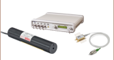
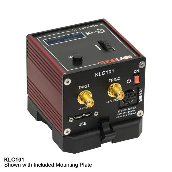
KLC101
K-Cube® Liquid Crystal Controller
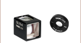
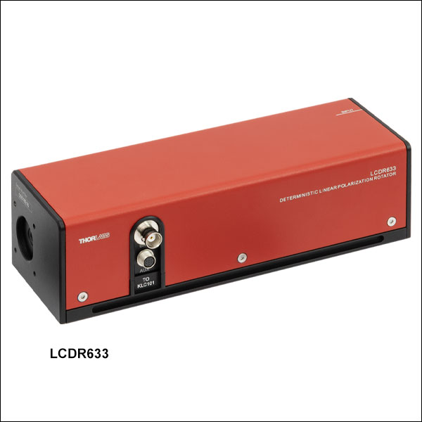
LCDR633
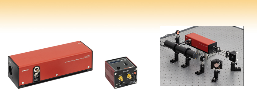
Deterministic Linear Polarization Rotator
Application Idea
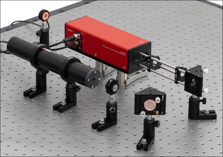
Irises and kinematic mirror mounts can be used to align the linearly polarized input laser beam.

Please Wait
| Table 1.1 Key Specsa | ||
|---|---|---|
| Operating Wavelength | 633 nm | |
| Input Optical Power | 0.1 to 300 mW | |
| Clear Aperture | Ø5.0 mm | |
| Angle of Incidence | 0° | |
| Output Azimuth Rotation Resolutionb | 0.1° | |
| Output Azimuth Accuracyb | ±2° | |
| Output Azimuth Stabilityb | <0.05° (RMS) | |
| Extinction Ratioc | >820:1 | |
| Linear Polarization Rotation Range | >360° | |
Features
- Rotate Arbitrary Linear Input Polarization Continuously Through >360°
- Feedback Design Stabilizes Output Azimuth
- 633 nm Operating Wavelength with Input Power Up to 300 mW
- Mounting Features on Input and Output Ports
- 4-40 Taps fo 30 mm Cage System
- Internal Threading for SM1 Lens Tubes
- Requires KLC101 LC Controller (Sold Separately Below)
Thorlabs' LCDR633 Liquid Crystal Deterministic Rotator (LCDR), controlled by the KLC101 Liquid Crystal Controller, can continuously rotate the polarization state of an arbitrary linearly polarized input beam through over 360° with no mechanical movement involved. An internal closed-loop feedback mechanism analyzes the output beam and adjusts the driving voltage of the liquid crystal retarder to stabilize the output azimuth (as illustrated in Figure 1.2).
The LC polarization rotator consists of a liquid crystal variable retarder and two quartz zero-order quarter-wave plates; the LC retarder and wave plates have their fast axes oriented at 45° with respect to each other, as shown in Figure 1.2. With arbitrarily linearly polarized light incident on the polarization rotator, azimuth rotation of the output polarization can be achieved by adjusting the liquid crystal retardation. The linearly polarized input beam can have any arbitrary polarization angle.
Click to Enlarge
Figure 1.2 Schematic Showing the Operating Principle of the Azimuth Rotation and Detection Modules
Operating Principle
The LCDR incorporates two modules: an azimuth rotation module that implements the rotation of linearly polarized input light, and the azimuth detection module that detects the azimuth orientation of the output light. The communication between these two modules is what makes this closed-loop feedback system deterministic.
The azimuth rotation module consists of a liquid crystal variable retarder and two quartz zero-order quarter-wave plates. The LC retarder and wave plates have their fast axes oriented at 45° with respect to each other. Such a configuration allows smooth and continuous rotation of arbitrarily linearly polarized input light.
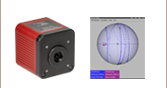
The azimuth detection module contains photodiodes which collect the intensity of four linear polarization states of the sampled light: -45°, 0°, 45°, and 90°. These intensities are then used to compute the actual output azimuth.
Utilizing the azimuth rotation module combined with the azimuth detection module and a feedback control circuit (integrated with the KLC101 LC controller), the LCDR can eliminate the azimuth fluctuation in linearly polarized light, achieving output azimuth stabilization within 0.05° (RMS), which is ideal for applications requiring precise and stable linear polarizations, such as polarization photo alignment, direct laser writing (with linear polarization modulation), and linear polarization encoding in quantum optics, e.g., quantum key distribution (QKD), quantum computing, and quantum sensing.
Click to Enlarge
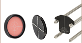
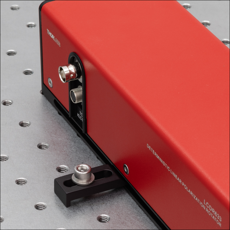
Figure 1.4 CL6 table clamps can be used to secure the LCDR633 rotator directly to an optical table via the slots on both of its sides.
Mounting and Alignment Features
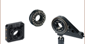
The input and output ports of the LCDR feature internal SM1 threading, which can be used to install externally SM1-threaded alignment targets or irises (not included). Both ports also have four 4-40 threaded holes for compatibility with our 30 mm cage systems. To aid in initial alignment, we recommend using cage assembly rods and our CP20D 30 mm cage system iris diaphragm, as shown in Figure 1.3.
Click to Enlarge
Figure 1.3 Irises and kinematic mirror mounts can be used to align the linearly polarized input laser beam.
The LCDR features pairs of M4 x 0.7 and 8-32 mounting holes on either the bottom or side of the rotator housing for mounting to Ø1/2" optical posts or Ø1" pedestal posts. There are two sets on the bottom of the housing, one set centered on the housing and one set centered on the optical axis. The side-located mounting holes are ideal for spatially constrained systems where cable protrusion out of the side of the rotator is undesirable (in this case, the cables would connect to the top surface). Alternatively, two slots on either side of the rotator housing allow the LCDR to be mounted directly to an optical table with table clamps, such as our CL6 clamps (not included), as shown in Figure 1.4, resulting in a minimum beam height of 28.0 mm (1.10") while minimizing vibration and drift.
Voltage Controller
The KLC101 liquid crystal controller is designed with the feedback needs of the LCDR633 in mind and provides active DC offset compensation while applying an AC voltage (0 to 25 Vrms). The DC offset compensation automatically zeros the DC bias across the LC device in order to counteract the buildup of charge.
Note: The KLC101 controller that is used must have been manufactured in 2025 or later (serial numbers larger than 39486044) and use firmware version 1.14.64 or higher; please click here to download the latest firmware version. Earlier versions of this controller or those with older firmware will not function properly with the LCDR633 polarization rotator.
| Table 2.1 Specifications | ||
|---|---|---|
| Operating Wavelength | 633 nm | |
| Linear Polarization Rotation Range | >360° | |
| Input Beam Polarization State | Arbitrary Linear Polarized | |
| Extinction Ratioa | >820:1 | |
| Input Optical Power | 0.1 to 300 mW | |
| Typical Transmission | >82% | |
| Clear Aperture | Ø5.0 mm | |
| Angle of Incidence | 0° | |
| Output Azimuth Rotation Resolutionb | 0.1° | |
| Output Azimuth Accuracyb | ±2° | |
| Output Azimuth Stabilityb | <0.05° (RMS) | |
| Output Ellipticity Tolerance | ±2° | |
| Operating Temperature | 10 to 40 °C | |
| Storage Temperature | 0 to 40 °C | |
| Housing Dimensions (W x D x H)c | 222.0 mm x 75.0 mm x 63.0 mm (8.74" x 2.95" x 2.48") |
|
| Weight | 1.62 kg (3.57 lbs) | |
Click to Enlarge
Figure 2.2 This plot shows the typical output azimuth stability provided by the LCDR633 rotator when the output azimuth is held for 10 s at various angles.
Click to Enlarge
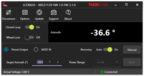
Figure 3.1 Screenshot of the GUI interface
Software
Version 1.0.0
GUI Interface for controlling the LCDR633 via a PC. To download, click the button below.
Software for the LCDR633 Liquid Crystal Deterministic Polarization Rotator
The LCDR software user interface allows full control of the LCDR633 rotator's set azimuth, closed-loop feedback, and other settings. These settings can also be accessed from the KLC101 top panel.
| Posted Comments: | |
| No Comments Posted |

 Zoom
Zoom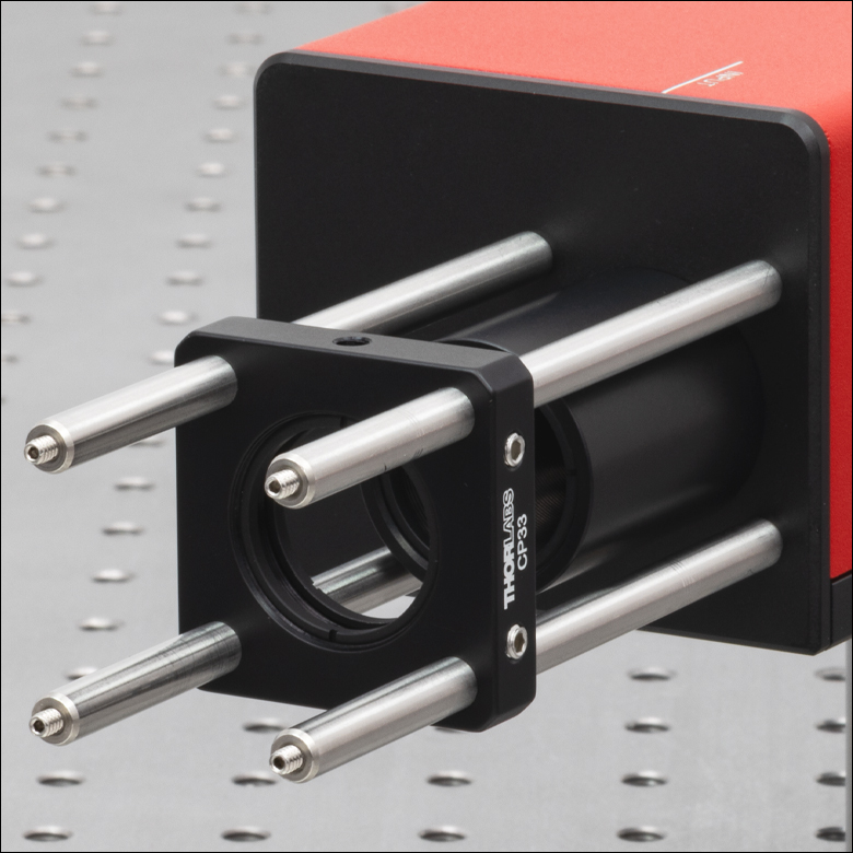
Click to Enlarge
Figure G1.2 The input and output ports are compatible with 30 mm cage system components and SM1-threaded components.
Click to Enlarge
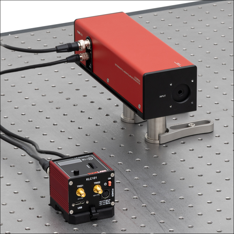
Figure G1.1 A KLC101 K-Cube controller is required to control the LCDR633 polarization rotator.
- 633 nm Operating Wavelength
- Ø5.0 mm Clear Aperture
- SM1-Threaded Entrance and Exit Apertures
- 8-32 (M4 x 0.7) Taps on Bottom and Side for Post Mounting
- Two Slots for Direct Table Mounting Using CL6 Clamps
Thorlabs' LCDR633 Liquid Crystal Polarization Rotator accepts arbitrarily linearly polarized light and can rotate the output polarization through >360°. A feedback mechanism detects and stabilizes the azimuth of the output light. The rotator includes 1.5 m long BNC and Hirose cables for use with the KLC101 LC controller, which is required and sold separately below. The KLC101 controller that is used must be manufactured in 2025 or later (serial numbers larger than 39486044) and use firmware version 1.14.64 or higher. Earlier versions of this controller or those with older firmware will not function properly with the LCDR633 polarization rotator.

 Zoom
Zoom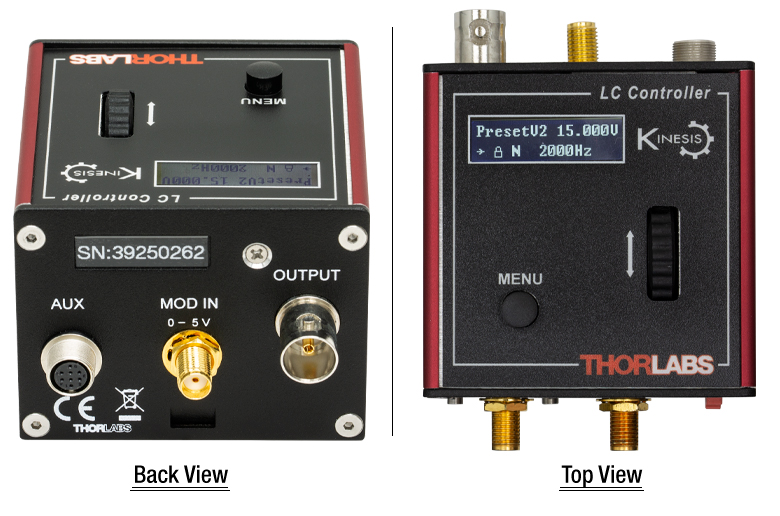
Click to Enlarge
Figure G2.1 Back and Top Views of the KLC101 K-Cube®
- Square-Wave Output Voltage with Adjustable Amplitude and Frequency
- 0 to ±25 VAC
- 500 Hz to 10 kHz (50% Duty Cycle)
- Maximum Output Current: 50 mA
- Operating Modes Include:
- Switching Between Two Voltage and Frequency Set Points at Frequencies of 0.1 to 150 Hz (50% Duty Cycle)
- User-Programmable Voltage Sequences
- Trigger Input and Output
- Edit Settings Using Device Top Panel or Control via USB Input from a PC
- Power Supply Not Included (See Below)
Thorlabs' KLC101 K-Cube Liquid Crystal Controller provides control of the LCDR633 liquid crystal polarization rotator and other liquid crystal devices. The digital display and controls on the top panel can be used to locally set the output voltage amplitude and frequency. The digital display includes a backlight that can be dimmed or turned off using the top panel menu options. Alternatively, a USB port allows the unit to be connected to a computer and controlled using the LCDR software (available in the Software tab above).
A MOD IN port on the back panel also allows the output voltage to be controlled using a 0 to 5 V input, with a 5 V input corresponding to a ±25 VAC output. The front of the unit contains two bidirectional trigger ports that can be used to read a 5 V external logic signal or output a 5 V logic signal to control external equipment.
Please note that this controller does not ship with a power supply. Compatible power supplies are listed below.
See the full KLC101 controller web presentation for more information on the features of this controller.
Note: The KLC101 controller that is used must have been manufactured in 2025 or later (serial numbers larger than 39486044) and use firmware version 1.14.64 or higher; please click here to download the latest firmware version. Earlier versions of this controller or those with older firmware will not function properly with the LCDR633 polarization rotator.

 Zoom
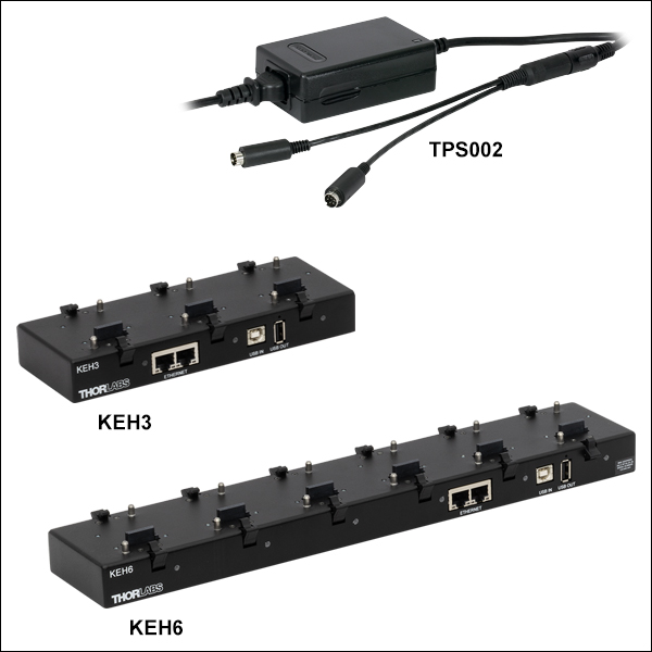
Zoom- Individual ±15 V/5 V Power Supply
- TPS002: For Up to Two K-Cubes® or T-Cubes™ with Mini-DIN Input*
- Ethernet and USB Controller Hubs Provide Power and Communications
- KEH3: For Up to Three K-Cubes or T-Cubes
- KEH6: For Up to Six K-Cubes or T-Cubes
The TPS002 supplies power for up to two K-Cubes* or T-Cubes. The cubes still require individual computer connection via USB cable.
The KEH3 and KEH6 Controller Hubs contain a fully compliant USB 2.0 hub circuit and provide all communications and power distribution for up to three (Item # KEH3) or six (Item # KEH6) K-Cubes or T-Cubes (using the KAP101 or KAP102 adapters, for T-Cubes), using only a single power connection. Additionally, the hubs have two Ethernet connection ports. The second Ethernet port or USB OUT port can be connected to the input on another Controller Hub to allow multiple Controller Hub connections while still only requiring a single Ethernet or USB cable from the host PC. The hubs draw a maximum current of 4.6 A; please verify that the cubes being used do not require a total current of more than 4.6 A.
For more information on the Controller Hubs, see the full web presentation.
*The TPS002 can only support one KNA-VIS or KNA-IR controller or one KLD101 driver and should not be used to power any additional units as that may exceed current limitations.