 Products Home / Motorized Stages / Motorized Rotation Stages and Mounts / Motorized Tilt and Rotation Stage with Integrated Controller
Motorized Tilt and Rotation Stage with Integrated Controller
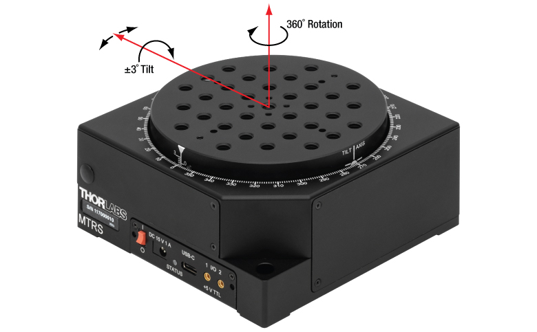
- ±3° Tilt and 360° Continuous Rotation
- Bidirectional Accuracy at ±0.05°
- Integrated DC Servo Motors and Controller
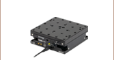
MTRS
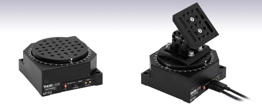
Motorized Tilt and Rotation Stage
AP180 Articulating Platform Mounted on MTRS Stage


Please Wait
| Key Specificationsa | ||
|---|---|---|
| Stage Specifications | Tilt | Rotation |
| Travel | ±3° | 360° (Continuous) |
| Maximum Velocity | 0.5 °/s | 1.5 °/s |
| Maximum Acceleration | 0.5 °/s2 | 1.5 °/s2 |
| Bidirectional Repeatability | 0.05° | ±0.05° |
| Min Incremental Movement | ±0.005° | ±0.005° |
| Bidirectional Accuracy | ±0.05° | ±0.05° |
| Horizontal Load Capacity | 5.0 kg (11.02 lbs) | |
| Vertical Load Capacity | 2.0 kg (4.41 lbs) | |
Click to Enlarge
Figure 1.1 Rotation and Tilt Motion Illustration
Click for Details
Figure 1.3 MTRS/M Mounting Features
Click for Details
Figure 1.2 MTRS Mounting Features
Features
- ±3° Tilt and 360° Continuous Rotation
- 5 kg Horizontal Load Capacity (Approximate)
- 5 V TTL Input and Output Trigger Ports
- USB-C Connectivity for Plug and Play PC-Controlled Operation
- Multiple Units Can be Connected to PC for Multi-Axis Applications
The MTRS(/M) Motorized Tilt and Rotation Stage features two DC servo motors and an integrated DC controller. The controller includes a USB-C port that can be connected to a PC. Coupling this with the user-friendly Kinesis software allows plug and play operation, with advanced custom motion control applications and sequences also possible using the extensive programming environment supplied. This programming library is compatible with many development tools such as LabVIEW, Visual Basic, Visual C++, C++ Builder, LabWindows/CVI, MATLAB, and Delphi.
With a 115 mm x 115 mm footprint and an array of tapped holes (Figures 1.2 and 1.3), the MTRS(/M) stage is compatible with Thorlabs' ORIC® Piezo Inertia Rotation and Translation (5 mm and 20 mm) Stages, the KVS30 Motorized Vertical Translation Stage, or the M30XY Motorized XY Translation Stage, as well as general optomechanical components. By combining stages, up to 5-axis adjustment can be achieved. To change the nominal starting angle from 0°, adapters such as the AP30 angled mounting plate or the AP180 adjustable angle mounting plate can be secured to the platform. For applications that might require long linear travel + rotation and tilt control, the MTRS(/M) can also be mounted on the DDS300(/M) or DDS600(/M) direct drive stages, among others.
Engravings at 1° intervals provide a visual reference for the rotation and tilt of the stage. There is also an engraved line on the side of the moving platform to mark the axis about which the platform rotates when tilt adjustments are made.
With both rotation and tilt control (Figure 1.1), the MTRS(/M) stage is useful for applications such as imaging surface imperfections. The stage is also suitable for use with laser sources, fiber optics, and other multi-axis stages.
These stages are compatible with our Kinesis software package, which can be downloaded here. Please see the Kinesis Software tab for more information. Each stage includes a 79" (2 m) USB A to USB C cable for remote connections, two 72" (1.8 m) MMCX-to-BNC input and output trigger cables, and a 15 V, 2.4 A power supply. CA3439 MMCX to SMA cables are available separately.
| Item # | MTRS(/M) | |
|---|---|---|
| Stage Specifications | Tilt | Rotation |
| Travel | ±3° | 360° (Continuous) |
| Maximum Velocity | 0.5 °/s | 1.5 °/s |
| Maximum Acceleration | 0.5 °/s2 | 1.5 °/s2 |
| Bidirectional Repeatability | 0.05° | ±0.05° |
| Min Incremental Movement | ±0.005° | ±0.005° |
| Bidirectional Accuracy | ±0.05° | ±0.05° |
| Backlash | ±0.05° | ±0.05° |
| Axis Wobble | ±0.01° | |
| Load Capacity | ||
| Horizontal Load | 5.0 kg (11.02 lbs) | |
| Vertical Load | 2.0 kg (4.41 lbs) | |
| Input Power Requirements | ||
| Voltage | 15 V Regulated DC | |
| Current | 500 mA (Peak) | |
| General Data | ||
| Motor Type | 2 x DC Servo Motors | |
| Dimensions (W x D x H) at 0° of Tilt |
115 mm x 115 mm x 57.1 mm (4.53" x 4.53" x 2.25") |
|
| Mass (Without Cables) | 1.47 kg (3.24 lbs) | |
Click to Enlarge
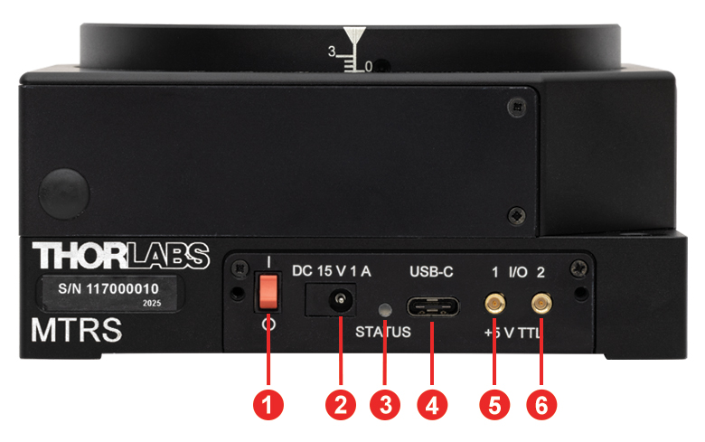
Figure 3.1 MTRS Front Panel
| Table 3.2 MTRS(/M) Front Panel | |
|---|---|
| Callout | Description |
| 1 | Power Switch |
| 2 | Power Supply Connector |
| 3 | Status LED |
| 4 | USB Type-C Connectora |
| 5 | Output Connector, MMCX Socket, 5 V TTLb |
| 6 | Input Connector, MMCX Socket, 5 V TTLb |
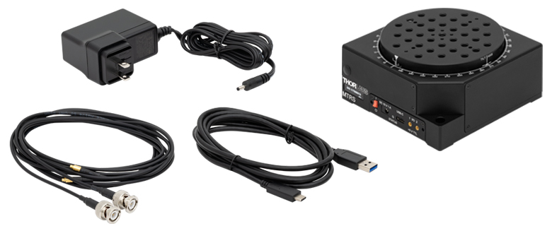
MTRS(/M) Shipping List
Software
Kinesis Version 1.14.58
The Kinesis Software Package, which includes a GUI for control of Thorlabs' Kinesis system controllers.
Also Available:
- Firmware Update Utilities
- Communications Protocol
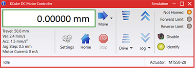
Figure 58A Kinesis GUI Screen
Thorlabs offers the Kinesis software package to drive our wide range of motion controllers. The software can be used to control devices in the Kinesis family, which covers a wide variety of motion controllers ranging from small, low-powered, single-channel drivers (such as the K-Cubes®) to high-power, multi-channel benchtop units and modular 19" rack nanopositioning systems (the MMR60x Rack System).
The Kinesis Software features .NET controls which can be used by 3rd party developers working in the latest C#, Visual Basic, LabVIEW™, or any .NET compatible languages to create custom applications. Low-level DLL libraries are included for applications not expected to use the .NET framework and APIs are included with each install. A Central Sequence Manager supports integration and synchronization of all Thorlabs motion control hardware.
By providing this common software platform, Thorlabs has ensured that users can mix and match any of our motion control devices in a single application, while only having to learn a single set of software tools. In this way, it is perfectly feasible to combine any of the controllers from single-axis to multi-axis systems and control all from a single, PC-based unified software interface.
The software package allows two methods of usage: graphical user interface (GUI) utilities for direct interaction with and control of the controllers 'out of the box', and a set of programming interfaces that allow custom-integrated positioning and alignment solutions to be easily programmed in the development language of choice.
Thorlabs' Kinesis software features new .NET controls which can be used by third-party developers working in the latest C#, Visual Basic, LabVIEW™, or any .NET compatible languages to create custom applications.
C#
This programming language is designed to allow multiple programming paradigms, or languages, to be used, thus allowing for complex problems to be solved in an easy or efficient manner. It encompasses typing, imperative, declarative, functional, generic, object-oriented, and component-oriented programming. By providing functionality with this common software platform, Thorlabs has ensured that users can easily mix and match any of the Kinesis controllers in a single application, while only having to learn a single set of software tools. In this way, it is perfectly feasible to combine any of the controllers from the low-powered, single-axis to the high-powered, multi-axis systems and control all from a single, PC-based unified software interface.
The Kinesis System Software allows two methods of usage: graphical user interface (GUI) utilities for direct interaction and control of the controllers 'out of the box', and a set of programming interfaces that allow custom-integrated positioning and alignment solutions to be easily programmed in the development language of choice.
For a collection of example projects that can be compiled and run to demonstrate the different ways in which developers can build on the Kinesis motion control libraries, click on the links below. Please note that a separate integrated development environment (IDE) (e.g., Microsoft Visual Studio) will be required to execute the Quick Start examples. The C# example projects can be executed using the included .NET controls in the Kinesis software package (see the Kinesis Software tab for details).
 |
Click Here for the Kinesis with C# Quick Start Guide Click Here for C# Example Projects Click Here for Quick Start Device Control Examples |
|
LabVIEW
LabVIEW can be used to communicate with any Kinesis-based controller via .NET controls. In LabVIEW, you build a user interface, known as a front panel, with a set of tools and objects and then add code using graphical representations of functions to control the front panel objects. The LabVIEW tutorial, provided below, provides some information on using the .NET controls to create control GUIs for Kinesis-driven devices within LabVIEW. It includes an overview with basic information about using controllers in LabVIEW and explains the setup procedure that needs to be completed before using a LabVIEW GUI to operate a device.
 |
Click Here to View the LabVIEW Guide Click Here to View the Kinesis with LabVIEW Overview Page |
|
| Posted Comments: | |
| No Comments Posted |
Rotation Mount and Stage Selection Guide
Thorlabs offers a wide variety of manual and motorized rotation mounts and stages. Rotation mounts are designed with an inner bore to mount a Ø1/2", Ø1", or Ø2" optic, while rotation stages are designed with mounting taps to attach a variety of components or systems. Motorized options are powered by a DC Servo motor, 2 phase stepper motor, piezo inertia motor, or an Elliptec™ resonant piezo motor. Each offers 360° of continuous rotation.
Manual Rotation Mounts
| Rotation Mounts for Ø1/2" Optics | |||||||
|---|---|---|---|---|---|---|---|
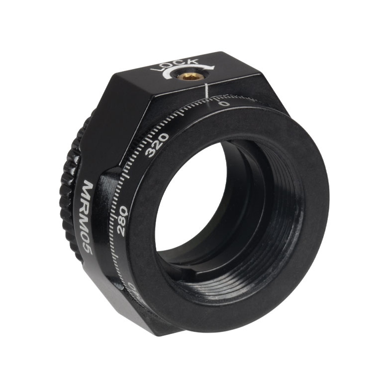
| Item # | MRM05(/M) | RSP05(/M) | CRM05 | PRM05(/M)a | SRM05 | KS05RS | CT104 |
| Click Photo to Enlarge |
 |
 |
 |
 |
 |
 |
 |
| Features | Mini Series | Standard | External SM1 (1.035"-40) Threads |
Micrometer | 16 mm Cage-Compatible | ±4° Kinematic Tip/Tilt Adjustment Plus Rotation | Compatible with 30 mm Cage Translation Stages and 1/4" Translation Stagesb |
| Additional Details | |||||||
| Rotation Mounts for Ø1" Optics | ||||||||
|---|---|---|---|---|---|---|---|---|
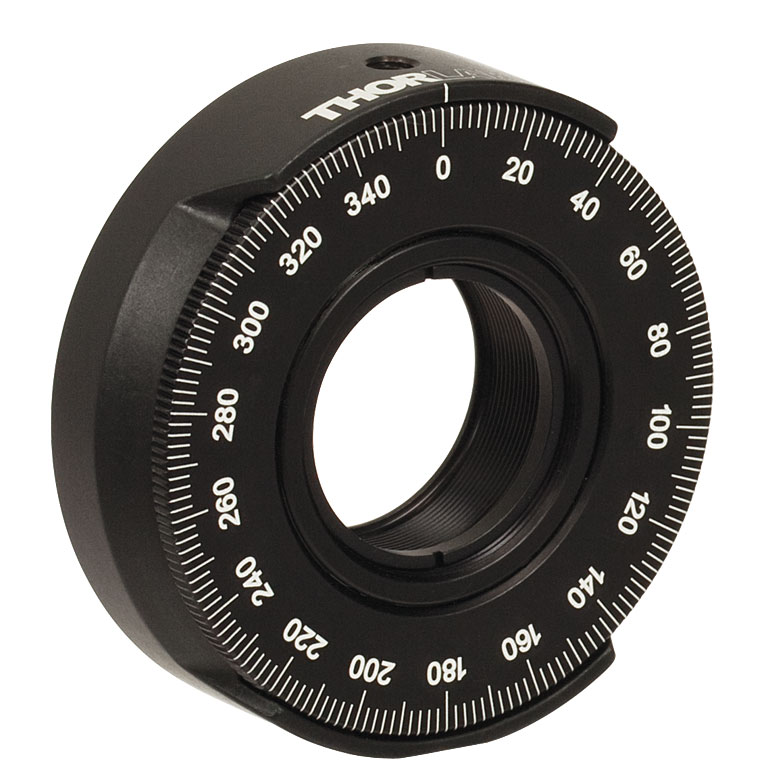
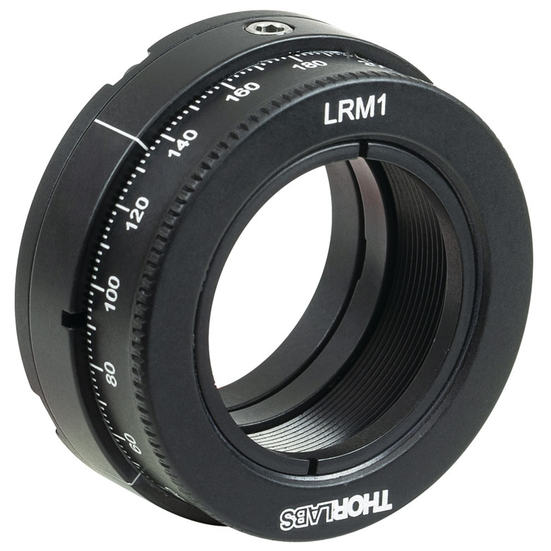
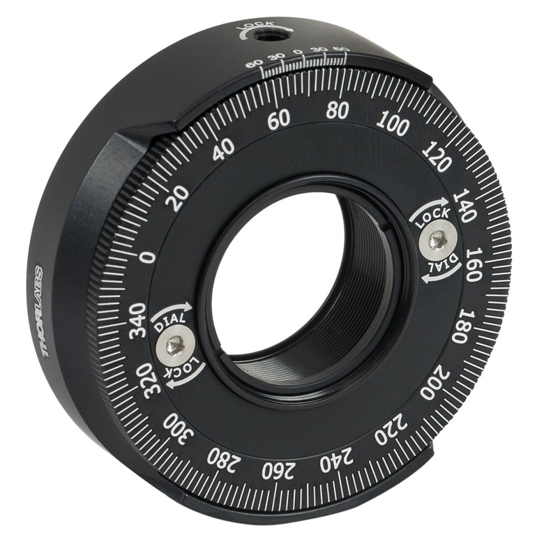
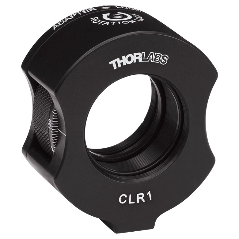
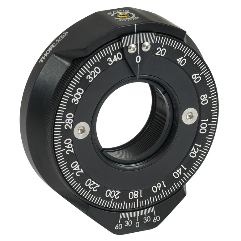
| Item # | RSP1(/M) | LRM1 | RSP1D(/M) | DLM1(/M) | CLR1(/M) | RSP1X15(/M) | RSP1X225(/M) | PRM1(/M)a |
| Click Photo to Enlarge |
 |
 |
 |
 |
 |
 |
|
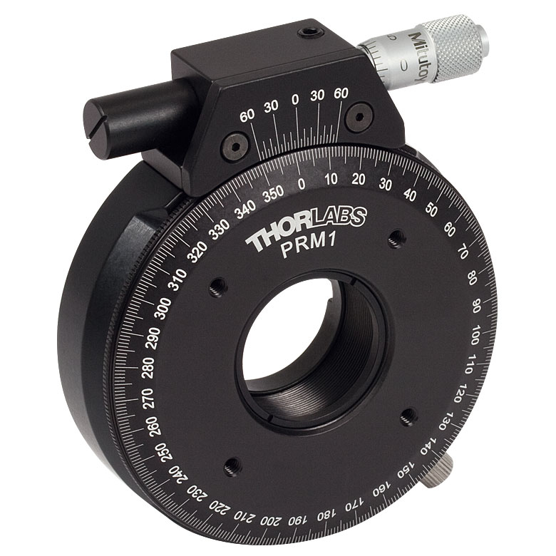 |
| Features | Standard | External SM1 (1.035"-40) Threads |
Adjustable Zero | Two Independently Rotating Carriages | Rotates Optic Within Fixed Lens Tube System |
Continuous 360° Rotation or 15° Increments |
Continuous 360° Rotation or 22.5° Increments |
Micrometer |
| Additional Details | ||||||||
| Rotation Mounts for Ø1" Optics | ||||||
|---|---|---|---|---|---|---|
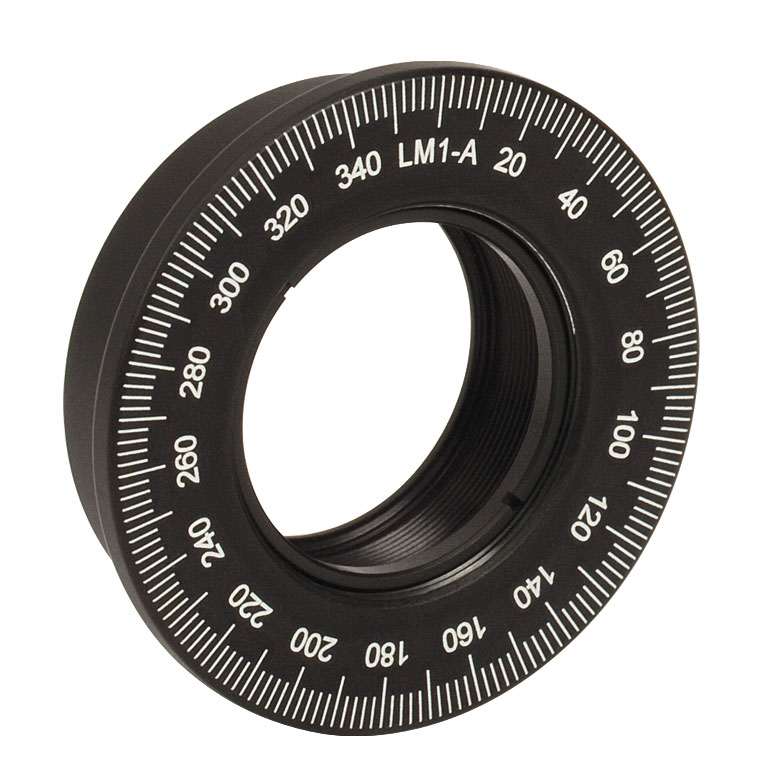
| Item # | LM1-A & LM1-B(/M) |
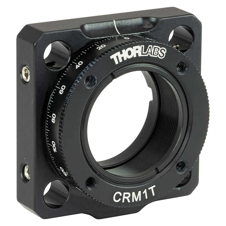
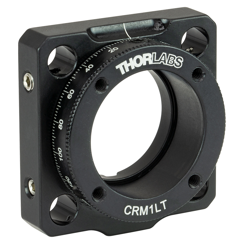
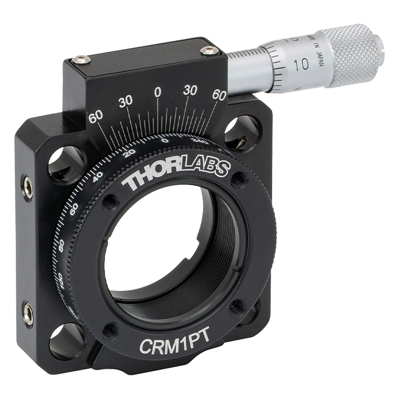
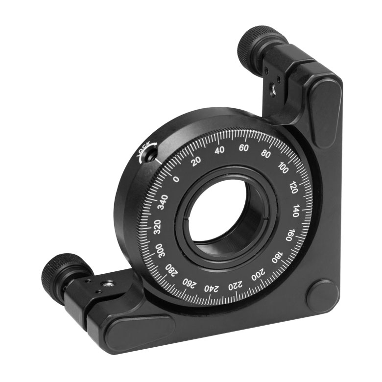
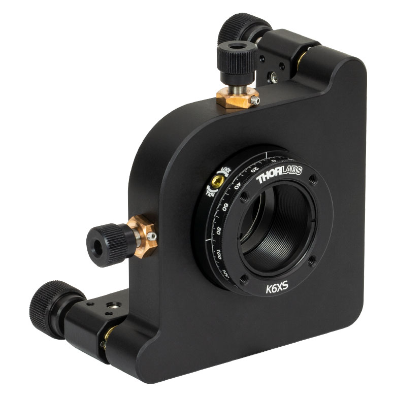
CRM1T(/M) | CRM1LT(/M) | CRM1PT(/M) | KS1RS | K6XS |
| Click Photo to Enlarge |
  |
 |
 |
 |
 |
 |
| Features | Optic Carriage Rotates Within Mounting Ring | 30 mm Cage-Compatiblea | 30 mm Cage-Compatible for Thick Opticsa |
30 mm Cage-Compatible with Micrometera |
±4° Kinematic Tip/Tilt Adjustment Plus Rotation | Six-Axis Kinematic Mounta |
| Additional Details | ||||||
| Rotation Mounts for Ø2" Optics | |||||||
|---|---|---|---|---|---|---|---|
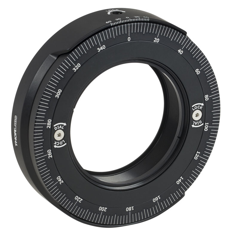
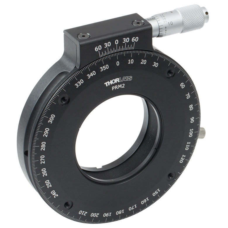
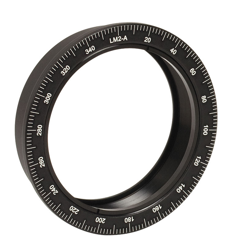
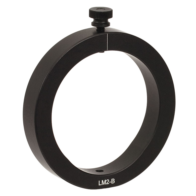
| Item # | RSP2(/M) | RSP2D(/M) | PRM2(/M) | LM2-A & LM2-B(/M) |
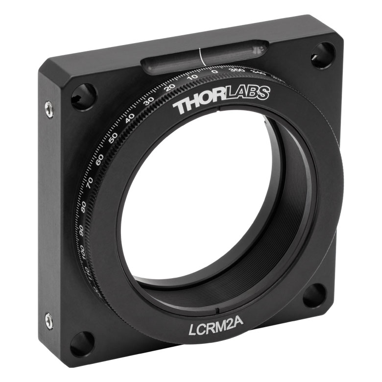
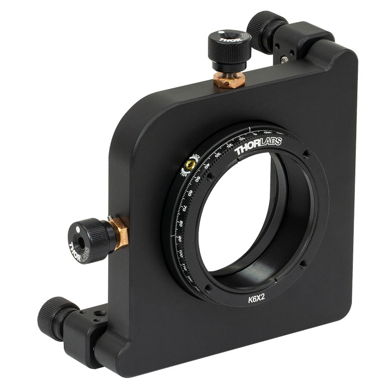
LCRM2A(/M) | KS2RS | K6X2 |
| Click Photo to Enlarge | 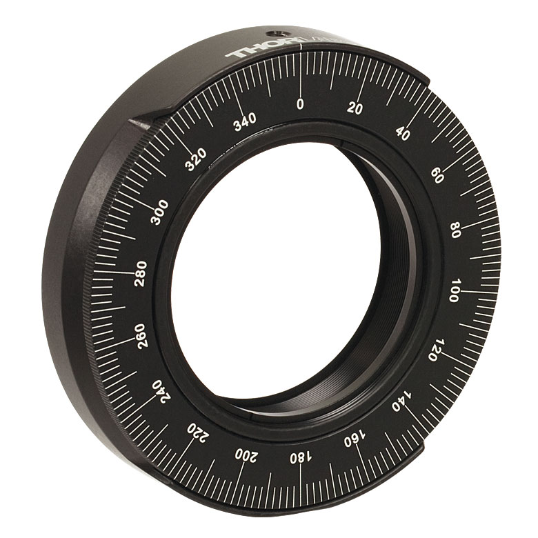 |
 |
 |
  |
 |
 |
 |
| Features | Standard | Adjustable Zero |
Micrometer | Optic Carriage Rotates Within Mounting Ring | 60 mm Cage-Compatible | ±4° Kinematic Tip/Tilt Adjustment Plus Rotation | Six-Axis Kinematic Mount |
| Additional Details | |||||||
Manual Rotation Stages
| Manual Rotation Stages | ||||||
|---|---|---|---|---|---|---|
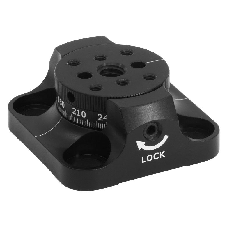
| Item # | RP005(/M) | PR005(/M) | MSRP01(/M) | RP01(/M) | RP03(/M) | QRP02(/M) |
| Click Photo to Enlarge |
 |
 |
 |
 |
 |
 |
| Features | Standard | Two Hard Stops | ||||
| Additional Details | ||||||
| Manual Rotation Stages | ||||||
|---|---|---|---|---|---|---|
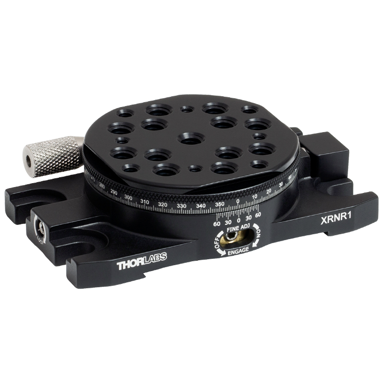
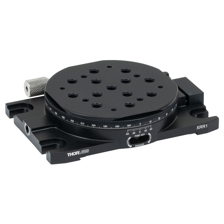
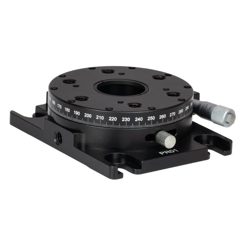
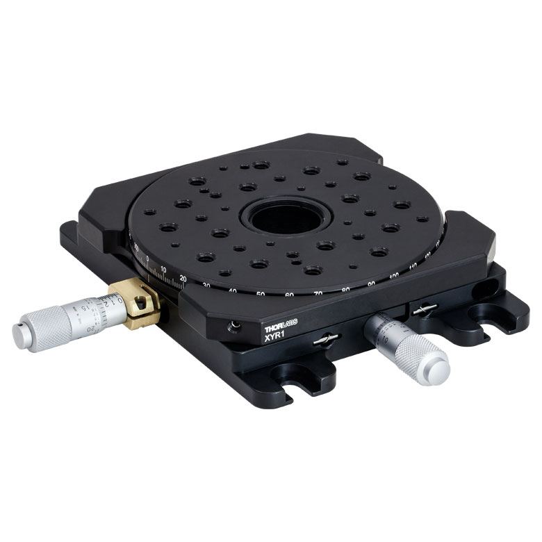
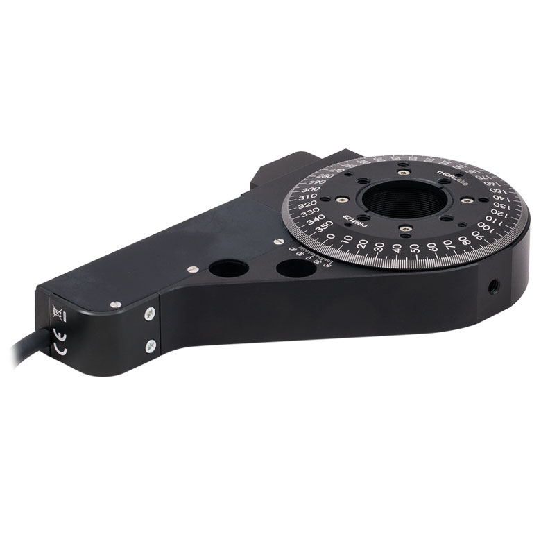
| Item # | XRNR1(/M) | XRR1(/M) | PR01(/M) | CR1(/M) | XYR1(/M) | OCT-XYR1(/M) |
| Click Photo to Enlarge |
 |
 |
 |
 |
 |
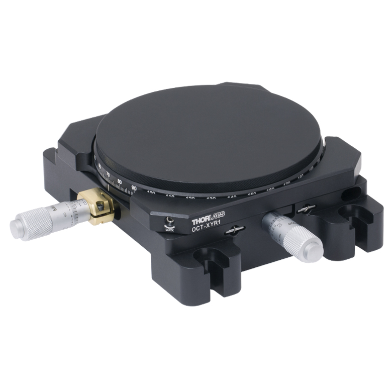 |
| Features | Fine Rotation Adjuster and 2" Wide Dovetail Quick Connect |
Fine Rotation Adjuster and 3" Wide Dovetail Quick Connect |
Fine Rotation Adjuster and SM1-Threaded Central Aperture |
Fine Pitch Worm Gear | Rotation and 1/2" Linear XY Translation | |
| Additional Details | ||||||
Motorized Rotation Mounts and Stages
| Motorized Rotation Mounts and Stages with Central Clear Apertures | |||||
|---|---|---|---|---|---|
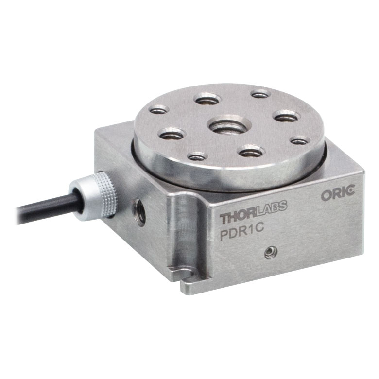
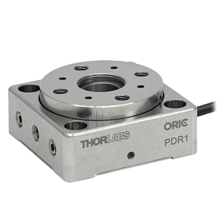
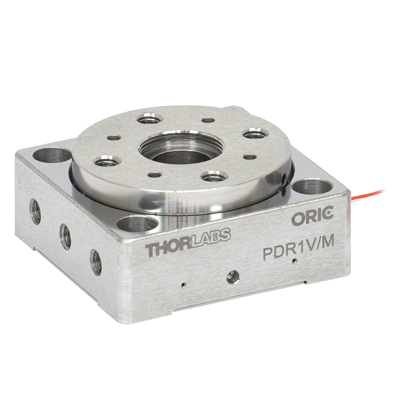
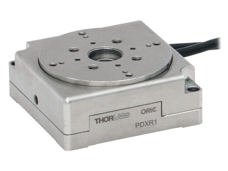
| Item # | DDR25(/M) | PDR1C(/M) | PDR1(/M) | PDR1V(/M) | PDXR1(/M) |
| Click Photo to Enlarge |
 |
 |
 |
 |
 |
| Features | Compatible with SM05 Lens Tubes, 16 mm Cage System, & 30 mm Cage System |
Compatible with 16 mm Cage System |
Compatible with SM05 Lens Tubes & 30 mm Cage System |
Vacuum-Compatible; Also Compatible with SM05 Lens Tubes & 30 mm Cage System |
Compatible with SM05 Lens Tubes & 30 mm Cage System |
| Additional Details | |||||
| Motorized Rotation Mounts and Stages with Central Clear Apertures | |||||||
|---|---|---|---|---|---|---|---|
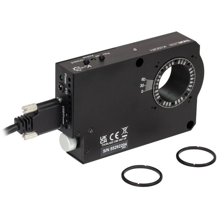
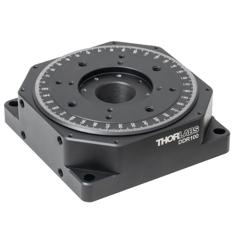
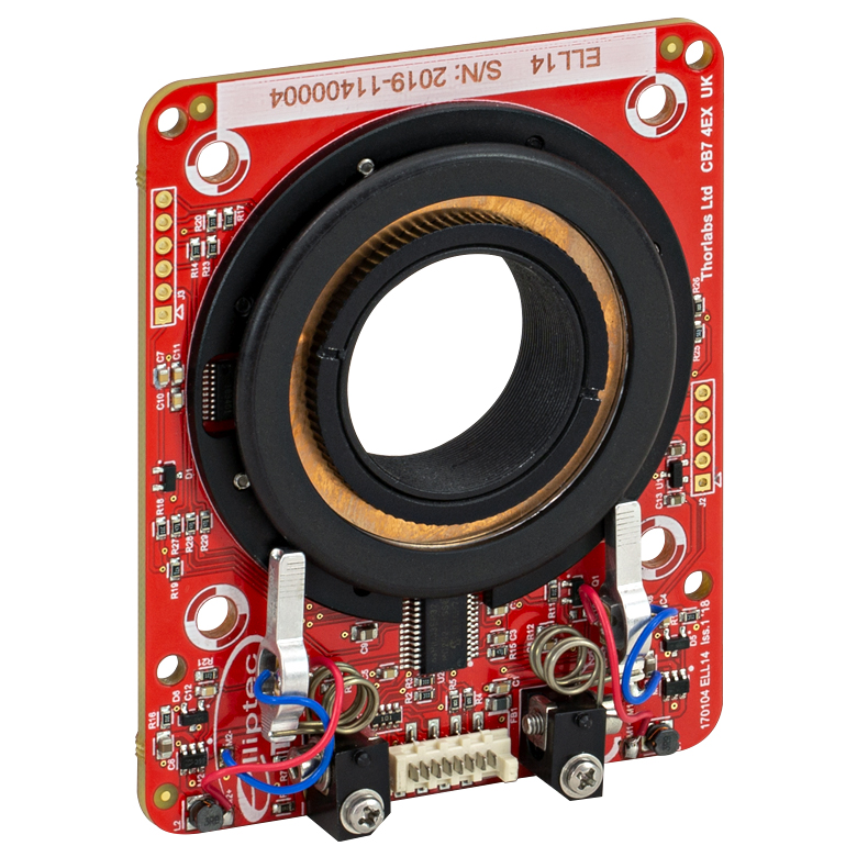
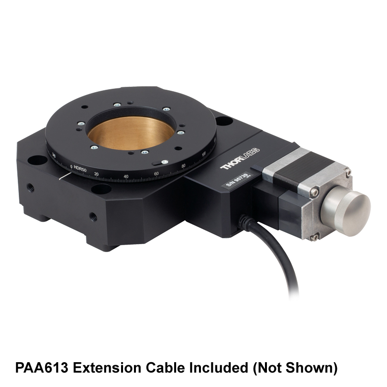
| Item # | K10CR1(/M) | PRM1Z8(/M)a | DDR100(/M) | ELL16 | ELL14 | ELL21(/M) | HDR50(/M) |
| Click Photo to Enlarge |
 |
 |
 |
 |
 |
 |
 |
| Features | Compatible with SM1 Lens Tubes & 30 mm Cage System | Compatible with SM1 Lens Tubes, 16 mm Cage System, 30 mm Cage System |
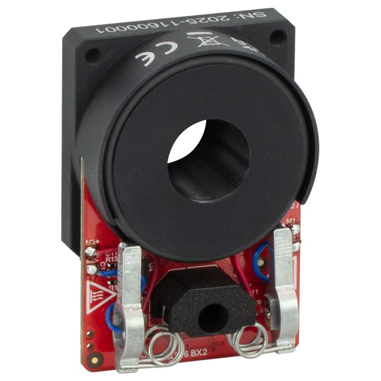
Compatible with SM05 Lens Tubes, Open Frame Design for OEM Applications |
Compatible with SM1 Lens Tubes, Open Frame Design for OEM Applications |
Compatible with SM2 Lens Tubes, Open Frame Design for OEM Applications |
Compatible with SM2 Lens Tubes |
|
| Additional Details | |||||||
| Motorized Rotation Mounts and Stages with Tapped Platforms | ||
|---|---|---|
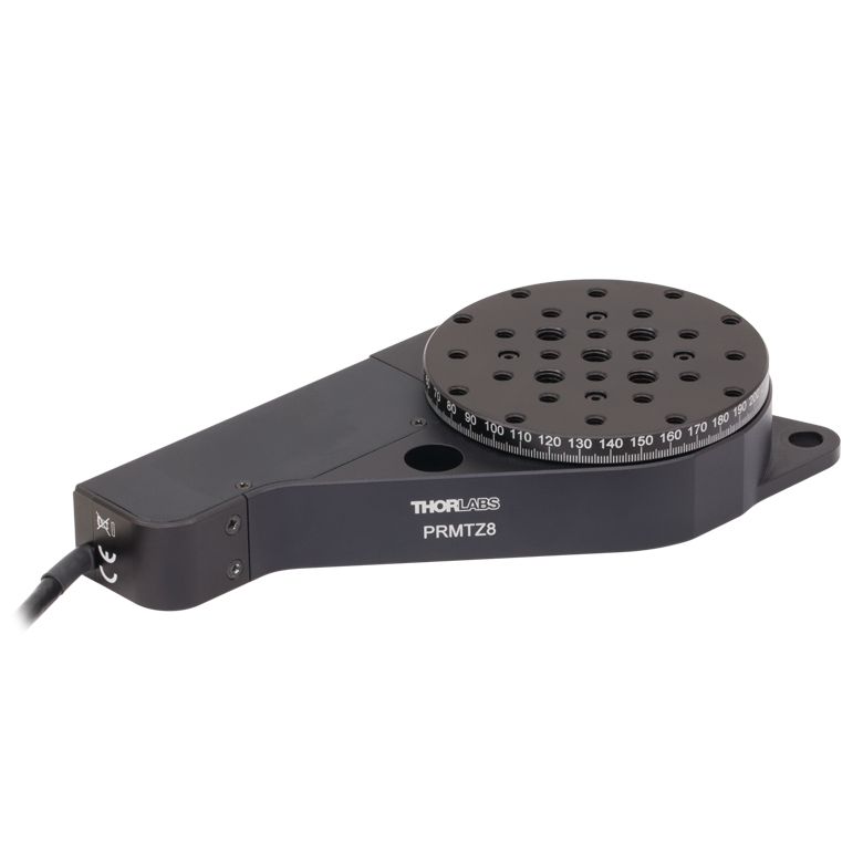
| Item # | PRMTZ8(/M)a | ELL18(/M)b |
| Click Photo to Enlarge |
 |
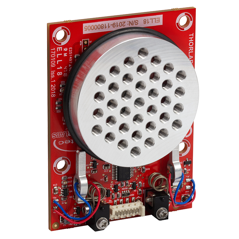 |
| Features | Tapped Mounting Platform for Mounting Prisms or Other Optics | Tapped Mounting Platform, Open Frame Design for OEM Applications |
| Additional Details | ||