 Products Home
Piezo-Based Fiber Phase Shifter

- Use in Closed- or Open-Loop Configurations to Shift the Phase of Light in Fiber
- Shift the Phase of Light Up to 6.5λ (13π radians)
- Wavelength Range: 1310 to 1550 nm
FVP155
Piezo-Based Fiber Phase Shifter
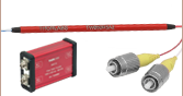
Application Idea
An FVP155 Phase Shifter is controlled by a KPC101 K-Cube® Piezo Controller.


Please Wait
Features
Click to Enlarge
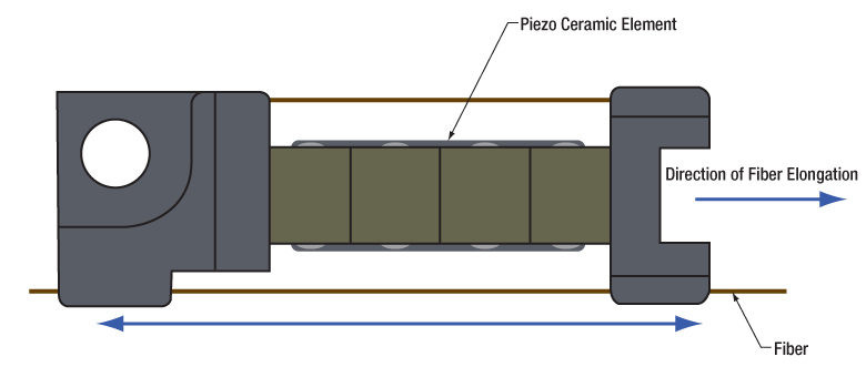
Figure 1.1 Schematic of the FVP155 Piezo-Based Fiber Phase Shifter
- Phase Shifts Up to 6.5λ (13π Radians)
- Input Drive Frequencies Up to 20 kHz
- Input Wavelength:1310 to 1550 nm
- Use in Closed- or Open-Loop Configurations
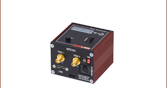
The FVP155 Piezo-Based Fiber Phase Shifter alters the optical phase of 1310 to 1550 nm light by stretching the single-mode fiber that goes through the device. The fiber is fixed to both ends of a piezoelectric ceramic, which elongates and thus stretches the fiber via the piezoelectric effect; see Figure 1.1 for a schematic diagram. The FVP155 phase shifter can produce a phase stroke of about 6.5λ (13π) at 150 V and operates with input frequencies as high as 20 kHz while maintaining a phase stroke of at least λ (2π). Please see the Graphs tab for typical graphs of the phase stroke versus the input voltage (Figure 3.1) and the phase stroke versus frequency (Figure 3.2). Note that the connectors on the device are narrow key FC/PC (2.0 wide) and that the device can be clamped to an optical table using a CL6 clamp, if needed.
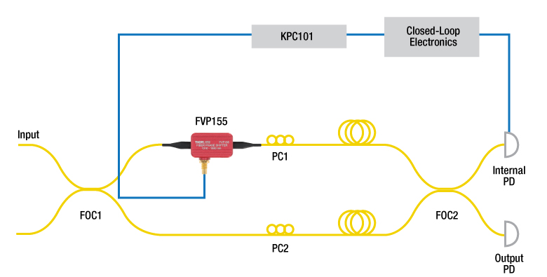
Click to Enlarge
Figure 1.2 The FVP155 Piezo-Based Fiber Phase Shifter can be integrated into a fiber interferometer to stabilize the path length using a KPC101 K-Cube® piezo controller. FOC = Fiber Optic Coupler, PC = Polarization Controller, PD = Photodetector.
The FVP155 phase shifter can be controlled by many of Thorlabs' piezo controllers via the SMC input on the device. For a list of compatible devices and their bandwidths, see Table 4.1 in the Controller Selection Guide tab. The FVP155 phase shifter is also equipped with a thermal switch to prevent damage to the device under high temperatures. When the device overheats, the circuit will be broken, and it will automatically reconnect when the temperature drops to around 50 °C. Since the device heats up faster when modulated at higher frequencies, we provide a list of recommended maximum voltages as a function of frequency to prevent overheating in Table 2.2 in the Specs tab, for reference.
Fiber phase shifters are versatile devices with applications in numerous fields, as listed above. By precisely controlling and modulating the phase of the input optical signal, they enable high-precision measurements, sensing, and laser technologies. Figure 1.2 shows a schematic for integrating the device into a fiber interferometer to stabilize the path length.
| Table 2.1 FVP155 Phase Shifter Specificationsa | |
|---|---|
| Drive Voltage Range | 0 - 150 V |
| Phase Stroke at 150 V and 1 kHzb | 13π radians ± 15% |
| Half-Wave Voltage | <11 V |
| Capacitancec | 200 nF ± 15% |
| Resonant Frequency | 80 kHz ± 15% |
| Insertion Loss | <0.1 dB (Without Connectors) |
| Residual Amplitude Modulation | <0.15% |
| Operating Wavelength | 1310 - 1550 nm |
| Operating Temperature | 0 - 50 °C |
| Electrical Connector | SMC Male |
| Fiber Type | SM1550P |
| Fiber Connectors | FC/PC Narrow Key (2.0 mm) |
| Storage Temperature | -40 - 85 °C |
| Dimensionsd (L x W x H) | With Fiber: 2000.0 mm × 28.2 mm × 12.0 mm (78.74" x 1.11" x 0.47") Housing With Connector: 29.0 mm × 28.2 mm × 12.0 mm (1.14" x 1.11" x 0.47") Housing Only: 29.0 mm × 17.0 mm × 12.0 mm (1.14" x 0.67" x 0.47") |
| Table 2.2 FVP155 Phase Shifter Recommended Voltage Limitsa | ||
|---|---|---|
| Frequency | Voltage Limit | Phase Shift |
| 2.0 kHz | 150 V | 14π radians |
| 2.5 kHz | 105 V | 11π radians |
| 3.5 kHz | 90 V | 10π radians |
| 5.0 kHz | 75 V | 9π radians |
| 8.0 kHz | 60 V | 8π radians |
| 11.0 kHz | 55 V | 7π radians |
| 15.0 kHz | 50 V | 6π radians |
| 20.0 kHz | 45 V | 4π radians |
Performance Graphs
All FVP155 phase shifter performance graphs are typical at 25°C, unless otherwise stated.

Click to Enlarge
Click for Raw Data
Figure 3.1 Typical FVP155 Phase Shifter Phase Stroke Versus Input Voltage at 1550 nm, Measured With a 2 kHz Input Modulation Frequency
Click to Enlarge
Click for Raw Data
Figure 3.3 Sample data for FVP155 Phase Shifter Half-Wave Voltage Versus Frequency at 1550 nm. The data shown is representative and may vary device-to-device.
Click to Enlarge
Click for Raw Data
Figure 3.2 Sample data for FVP155 Phase Shifter Phase Stroke Versus Frequency at 1550 nm. The data shown is representative and may vary device-to-device.
| Table 4.1 FVP155 Phase Shifter Controller Selection Guide | ||||||
|---|---|---|---|---|---|---|
| Item # | Channels | Bandwidth | Voltage Range | Maximum Current | Suggested Bandwidtha | Recommended Cable |
| BPC301 | 1 | 10 kHz (1 µF Load, 1 Vpp) | 0 - 150 V | 0.5 A | 3 kHz(150 Vpp) 26 kHz(30 Vpp) |
PAA100 or PAA101 |
| BPC303 | 3 | 1 A | 3 kHz(150 Vpp) 30 kHz(30 Vpp) |
|||
| MPZ601 | 2 | 10 kHz (1 µF Load, 1 Vpp) | 0 - 75 V DC (Software) | 0.5 A | 10 kHz(75 Vpp) 26 kHz(30 Vpp) |
|
| 0 - 90 V DC (External Input) |
8 kHz(90 Vpp) 26 kHz(30 Vpp) |
|||||
| KPC101 | 1 | 1 kHz (1 µF Load, 1 Vpp) | 0 - 150 V | 0.012 A | 0.09 kHz(150 Vpp) 0.6 kHz(30 Vpp) |
|
| MDT694B | 1 | 9 kHz (No Load, Small Signal) 8.5 kHz (No Load, 150 Vpp) 200 Hz (1.4 µF Piezo, 150 Vpp)b |
0 - 150 V | 0.06 A | 0.6 kHz(150 Vpp) 3 kHz(30 Vpp) |
CA26XX Series |
| MDT693B | 3 | |||||
| BPA100 | 1 | See the Responsivity Curves on the Overview tab of the BPA100 Amplifier webpage | 0 - 150 V | 2.5 A | 20 kHz(150 Vpp) 30 kHz(30 Vpp) |
CA26XX and T4004 |
 (1)
(1)
| Posted Comments: | |
| No Comments Posted |