 Products Home / Optical Elements / Optical Filters / Spectral Filters / Hard-Coated NIR Bandpass Filters
Hard-Coated NIR Bandpass Filters
- >90% Transmission at Design Wavelength
- Pass Regions from 1 nm to 70 nm FWHM
- Ø12.5 mm or Ø25 mm Mounted Filters
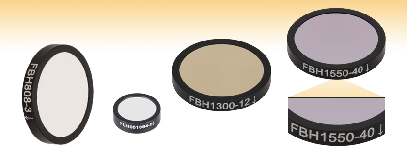
FBH808-3
Ø25 mm
FWHM: 3 nm
FLH051064-8
Ø12.5 mm
FWHM: 8 nm
FBH1300-12
Ø25 mm
FWHM: 12 nm
FBH1550-40
Ø25 mm
FWHM: 40 nm
Arrow Points in the Direction of Transmission


Please Wait
| General Specifications | |
|---|---|
| Out of Band Optical Density |
ODabs > 5 (700 to 1650 nm CWLs) ODabs > 4 (2000 nm CWL) |
| Transmission at CWL |
>90% |
| Angle of Incidence | 0° |
| Housing Diameter | 12.5 mm or 25 mm |
| Clear Aperture | Ø10.0 mm for Ø12.5 mm Ø21.1 mm for Ø25 mm |
| Mounted Thickness | 3.5 mm |
| Surface Quality | 60-40 Scratch-Dig |
| Coating | Hard Coated |
| Operating Temperature |
-40 to 90 °Ca |
| Edge Treatment | Mounted in Black Anodized Aluminum Ring |
| Edge Markings | Item #, Engraved Arrowb |
| Substrate | UV Fused Silicac |
| Damage Thresholdd | Item # FLH1064-10: Pulsed, 2 J/cm2 (1064 nm, 10 ns, 10 Hz, Ø1.020 mm) |
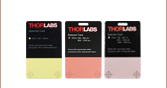
Packaging Redesign
Thorlabs is investing in green initiatives to replace plastic and foam optics packaging with more sustainable solutions. Leave feedback or learn more about what went into the design of our pilot program for Ø1" single optics here.

Click to Enlarge
Our new case is made from recyclable steel and includes recyclable paper inserts to protect the optic inside.

| Available Wavelengths |
|---|
| 700 - 750 nm |
| 760 - 790 nm |
| 800 - 840 nm |
| 850 - 890 nm |
| 900 - 940 nm |
| 950 - 990 nm |
| 1000 - 1064 nm |
| 1070 - 1250 nm |
| 1300 - 1490 nm |
| 1500 - 1590 nm |
| 1600 - 2000 nm |
Features
- Excellent Suppression in Rejection Region
- ODabs > 4 (CWL 2000 nm)
- ODabs > 5 (CWLs 700 to 1650 nm)
- 12.5 mm and 25 mm Outer Diameters Available
- Transmission Direction Engraved on Edge
- Transmission Direction Only Affects Backscatter and Reflection, Not Filter Performance
- Center Wavelengths from 700 nm to 2000 nm
- Hard-Coated Bandpass Filter Kits Sold Below
- Custom Bandpass Filter Sizes are Available by Contacting Tech Sales
Thorlabs' hard-coated bandpass filters, which are designed to provide enhanced isolation of key Yb:YAG, Nd:YLF, Nd:YAG, Tm:YAG, and diode laser lines, offer excellent suppression (ODabs > 4) in the blocking region while providing >90% transmission at the design wavelength. They are available with 12.5 mm or 25 mm outer diameters and are 3.5 mm thick, which allows the Ø25 mm filters to be used as drop-in replacements for our fluorescence emission filters.
The passbands of these filters range from 1 to 70 nm FWHM, depending on the center wavelength chosen, with steep cut-on and cut-off slopes. The center wavelength and passbands for these filters are specified for light normally incident on the surface. For angles of incidence (AOIs) greater than 0°, the band will shift toward a lower center wavelength and the shape of the pass band will change. Filters with passbands that have full width half maxima (FWHM) in the 1 to 5 nm range are particularly susceptible to these shifts. For more information, see the Tutorial tab.
These bandpass filters feature durable, hard-coated dielectric coatings on a UV fused silica substrate. The film construction is essentially a modified quarter-wave stack, using interference effects to isolate spectral bands. The dense coating on these filters allows them to be constructed using a single substrate, which yields a stable, long-lasting filter. This coating can withstand the normal cleaning and handling necessary when using any high-quality optical component.
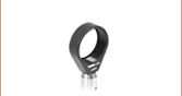
Each filter is housed in a black anodized aluminum ring that is labeled with an arrow indicating the design propagation direction. The ring makes handling easier and enhances the blocking OD by limiting scattering. These filters can be mounted in our extensive line of filter mounts and wheels. As the mounts are not threaded, retaining rings will be required to mount the filters in one of our internally threaded lens tubes. We do not recommend removing the filter from its mount as the risk of damaging the filter is very high.
| Additional Bandpass Filters | ||||||
|---|---|---|---|---|---|---|
| UV/VIS Hard-Coated Bandpass Filters 300 - 694 nm CWLs |
Wedged Hard-Coated Bandpass Filters 532 - 785 nm CWLs |
NIR Hard-Coated Bandpass Filters 700 - 2000 nm CWLs |
IR Bandpass Filters 1750 - 12000 nm CWLs |
Bandpass Filter Kits | ||
| We also offer custom bandpass filters with other central wavelengths or FWHM. To request a quote, contact Tech Sales. | ||||||
| Damage Threshold Specifications | |
|---|---|
| Item # | Damage Threshold |
| FLH1064-10a | Pulsed: 2 J/cm2 (1064 nm, 10 ns, 10 Hz, Ø1.020 mm) |
Damage Threshold Data for Thorlabs' Hard-Coated Bandpass Filters
The specifications to the right are measured data for a selection of Thorlabs' hard-coated bandpass filters.
Laser Induced Damage Threshold Tutorial
The following is a general overview of how laser induced damage thresholds are measured and how the values may be utilized in determining the appropriateness of an optic for a given application. When choosing optics, it is important to understand the Laser Induced Damage Threshold (LIDT) of the optics being used. The LIDT for an optic greatly depends on the type of laser you are using. Continuous wave (CW) lasers typically cause damage from thermal effects (absorption either in the coating or in the substrate). Pulsed lasers, on the other hand, often strip electrons from the lattice structure of an optic before causing thermal damage. Note that the guideline presented here assumes room temperature operation and optics in new condition (i.e., within scratch-dig spec, surface free of contamination, etc.). Because dust or other particles on the surface of an optic can cause damage at lower thresholds, we recommend keeping surfaces clean and free of debris. For more information on cleaning optics, please see our Optics Cleaning tutorial.
Testing Method
Thorlabs' LIDT testing is done in compliance with ISO/DIS 11254 and ISO 21254 specifications.
First, a low-power/energy beam is directed to the optic under test. The optic is exposed in 10 locations to this laser beam for 30 seconds (CW) or for a number of pulses (pulse repetition frequency specified). After exposure, the optic is examined by a microscope (~100X magnification) for any visible damage. The number of locations that are damaged at a particular power/energy level is recorded. Next, the power/energy is either increased or decreased and the optic is exposed at 10 new locations. This process is repeated until damage is observed. The damage threshold is then assigned to be the highest power/energy that the optic can withstand without causing damage. A histogram such as that below represents the testing of one BB1-E02 mirror.
The photograph above is a protected aluminum-coated mirror after LIDT testing. In this particular test, it handled 0.43 J/cm2 (1064 nm, 10 ns pulse, 10 Hz, Ø1.000 mm) before damage.
| Example Test Data | |||
|---|---|---|---|
| Fluence | # of Tested Locations | Locations with Damage | Locations Without Damage |
| 1.50 J/cm2 | 10 | 0 | 10 |
| 1.75 J/cm2 | 10 | 0 | 10 |
| 2.00 J/cm2 | 10 | 0 | 10 |
| 2.25 J/cm2 | 10 | 1 | 9 |
| 3.00 J/cm2 | 10 | 1 | 9 |
| 5.00 J/cm2 | 10 | 9 | 1 |
According to the test, the damage threshold of the mirror was 2.00 J/cm2 (532 nm, 10 ns pulse, 10 Hz, Ø0.803 mm). Please keep in mind that these tests are performed on clean optics, as dirt and contamination can significantly lower the damage threshold of a component. While the test results are only representative of one coating run, Thorlabs specifies damage threshold values that account for coating variances.
Continuous Wave and Long-Pulse Lasers
When an optic is damaged by a continuous wave (CW) laser, it is usually due to the melting of the surface as a result of absorbing the laser's energy or damage to the optical coating (antireflection) [1]. Pulsed lasers with pulse lengths longer than 1 µs can be treated as CW lasers for LIDT discussions.
When pulse lengths are between 1 ns and 1 µs, laser-induced damage can occur either because of absorption or a dielectric breakdown (therefore, a user must check both CW and pulsed LIDT). Absorption is either due to an intrinsic property of the optic or due to surface irregularities; thus LIDT values are only valid for optics meeting or exceeding the surface quality specifications given by a manufacturer. While many optics can handle high power CW lasers, cemented (e.g., achromatic doublets) or highly absorptive (e.g., ND filters) optics tend to have lower CW damage thresholds. These lower thresholds are due to absorption or scattering in the cement or metal coating.
LIDT in linear power density vs. pulse length and spot size. For long pulses to CW, linear power density becomes a constant with spot size. This graph was obtained from [1].
Pulsed lasers with high pulse repetition frequencies (PRF) may behave similarly to CW beams. Unfortunately, this is highly dependent on factors such as absorption and thermal diffusivity, so there is no reliable method for determining when a high PRF laser will damage an optic due to thermal effects. For beams with a high PRF both the average and peak powers must be compared to the equivalent CW power. Additionally, for highly transparent materials, there is little to no drop in the LIDT with increasing PRF.
In order to use the specified CW damage threshold of an optic, it is necessary to know the following:
- Wavelength of your laser
- Beam diameter of your beam (1/e2)
- Approximate intensity profile of your beam (e.g., Gaussian)
- Linear power density of your beam (total power divided by 1/e2 beam diameter)
Thorlabs expresses LIDT for CW lasers as a linear power density measured in W/cm. In this regime, the LIDT given as a linear power density can be applied to any beam diameter; one does not need to compute an adjusted LIDT to adjust for changes in spot size, as demonstrated by the graph to the right. Average linear power density can be calculated using the equation below.

The calculation above assumes a uniform beam intensity profile. You must now consider hotspots in the beam or other non-uniform intensity profiles and roughly calculate a maximum power density. For reference, a Gaussian beam typically has a maximum power density that is twice that of the uniform beam (see lower right).
Now compare the maximum power density to that which is specified as the LIDT for the optic. If the optic was tested at a wavelength other than your operating wavelength, the damage threshold must be scaled appropriately. A good rule of thumb is that the damage threshold has a linear relationship with wavelength such that as you move to shorter wavelengths, the damage threshold decreases (i.e., a LIDT of 10 W/cm at 1310 nm scales to 5 W/cm at 655 nm):

While this rule of thumb provides a general trend, it is not a quantitative analysis of LIDT vs wavelength. In CW applications, for instance, damage scales more strongly with absorption in the coating and substrate, which does not necessarily scale well with wavelength. While the above procedure provides a good rule of thumb for LIDT values, please contact Tech Support if your wavelength is different from the specified LIDT wavelength. If your power density is less than the adjusted LIDT of the optic, then the optic should work for your application.
Please note that we have a buffer built in between the specified damage thresholds online and the tests which we have done, which accommodates variation between batches. Upon request, we can provide individual test information and a testing certificate. The damage analysis will be carried out on a similar optic (customer's optic will not be damaged). Testing may result in additional costs or lead times. Contact Tech Support for more information.
Pulsed Lasers
As previously stated, pulsed lasers typically induce a different type of damage to the optic than CW lasers. Pulsed lasers often do not heat the optic enough to damage it; instead, pulsed lasers produce strong electric fields capable of inducing dielectric breakdown in the material. Unfortunately, it can be very difficult to compare the LIDT specification of an optic to your laser. There are multiple regimes in which a pulsed laser can damage an optic and this is based on the laser's pulse length. The highlighted columns in the table below outline the relevant pulse lengths for our specified LIDT values.
Pulses shorter than 10-9 s cannot be compared to our specified LIDT values with much reliability. In this ultra-short-pulse regime various mechanics, such as multiphoton-avalanche ionization, take over as the predominate damage mechanism [2]. In contrast, pulses between 10-7 s and 10-4 s may cause damage to an optic either because of dielectric breakdown or thermal effects. This means that both CW and pulsed damage thresholds must be compared to the laser beam to determine whether the optic is suitable for your application.
| Pulse Duration | t < 10-9 s | 10-9 < t < 10-7 s | 10-7 < t < 10-4 s | t > 10-4 s |
|---|---|---|---|---|
| Damage Mechanism | Avalanche Ionization | Dielectric Breakdown | Dielectric Breakdown or Thermal | Thermal |
| Relevant Damage Specification | No Comparison (See Above) | Pulsed | Pulsed and CW | CW |
When comparing an LIDT specified for a pulsed laser to your laser, it is essential to know the following:
LIDT in energy density vs. pulse length and spot size. For short pulses, energy density becomes a constant with spot size. This graph was obtained from [1].
- Wavelength of your laser
- Energy density of your beam (total energy divided by 1/e2 area)
- Pulse length of your laser
- Pulse repetition frequency (prf) of your laser
- Beam diameter of your laser (1/e2 )
- Approximate intensity profile of your beam (e.g., Gaussian)
The energy density of your beam should be calculated in terms of J/cm2. The graph to the right shows why expressing the LIDT as an energy density provides the best metric for short pulse sources. In this regime, the LIDT given as an energy density can be applied to any beam diameter; one does not need to compute an adjusted LIDT to adjust for changes in spot size. This calculation assumes a uniform beam intensity profile. You must now adjust this energy density to account for hotspots or other nonuniform intensity profiles and roughly calculate a maximum energy density. For reference a Gaussian beam typically has a maximum energy density that is twice that of the 1/e2 beam.
Now compare the maximum energy density to that which is specified as the LIDT for the optic. If the optic was tested at a wavelength other than your operating wavelength, the damage threshold must be scaled appropriately [3]. A good rule of thumb is that the damage threshold has an inverse square root relationship with wavelength such that as you move to shorter wavelengths, the damage threshold decreases (i.e., a LIDT of 1 J/cm2 at 1064 nm scales to 0.7 J/cm2 at 532 nm):

You now have a wavelength-adjusted energy density, which you will use in the following step.
Beam diameter is also important to know when comparing damage thresholds. While the LIDT, when expressed in units of J/cm², scales independently of spot size; large beam sizes are more likely to illuminate a larger number of defects which can lead to greater variances in the LIDT [4]. For data presented here, a <1 mm beam size was used to measure the LIDT. For beams sizes greater than 5 mm, the LIDT (J/cm2) will not scale independently of beam diameter due to the larger size beam exposing more defects.
The pulse length must now be compensated for. The longer the pulse duration, the more energy the optic can handle. For pulse widths between 1 - 100 ns, an approximation is as follows:

Use this formula to calculate the Adjusted LIDT for an optic based on your pulse length. If your maximum energy density is less than this adjusted LIDT maximum energy density, then the optic should be suitable for your application. Keep in mind that this calculation is only used for pulses between 10-9 s and 10-7 s. For pulses between 10-7 s and 10-4 s, the CW LIDT must also be checked before deeming the optic appropriate for your application.
Please note that we have a buffer built in between the specified damage thresholds online and the tests which we have done, which accommodates variation between batches. Upon request, we can provide individual test information and a testing certificate. Contact Tech Support for more information.
[1] R. M. Wood, Optics and Laser Tech. 29, 517 (1998).
[2] Roger M. Wood, Laser-Induced Damage of Optical Materials (Institute of Physics Publishing, Philadelphia, PA, 2003).
[3] C. W. Carr et al., Phys. Rev. Lett. 91, 127402 (2003).
[4] N. Bloembergen, Appl. Opt. 12, 661 (1973).

In order to illustrate the process of determining whether a given laser system will damage an optic, a number of example calculations of laser induced damage threshold are given below. For assistance with performing similar calculations, we provide a spreadsheet calculator that can be downloaded by clicking the button to the right. To use the calculator, enter the specified LIDT value of the optic under consideration and the relevant parameters of your laser system in the green boxes. The spreadsheet will then calculate a linear power density for CW and pulsed systems, as well as an energy density value for pulsed systems. These values are used to calculate adjusted, scaled LIDT values for the optics based on accepted scaling laws. This calculator assumes a Gaussian beam profile, so a correction factor must be introduced for other beam shapes (uniform, etc.). The LIDT scaling laws are determined from empirical relationships; their accuracy is not guaranteed. Remember that absorption by optics or coatings can significantly reduce LIDT in some spectral regions. These LIDT values are not valid for ultrashort pulses less than one nanosecond in duration.
A Gaussian beam profile has about twice the maximum intensity of a uniform beam profile.
CW Laser Example
Suppose that a CW laser system at 1319 nm produces a 0.5 W Gaussian beam that has a 1/e2 diameter of 10 mm. A naive calculation of the average linear power density of this beam would yield a value of 0.5 W/cm, given by the total power divided by the beam diameter:
However, the maximum power density of a Gaussian beam is about twice the maximum power density of a uniform beam, as shown in the graph to the right. Therefore, a more accurate determination of the maximum linear power density of the system is 1 W/cm.
An AC127-030-C achromatic doublet lens has a specified CW LIDT of 350 W/cm, as tested at 1550 nm. CW damage threshold values typically scale directly with the wavelength of the laser source, so this yields an adjusted LIDT value:
The adjusted LIDT value of 350 W/cm x (1319 nm / 1550 nm) = 298 W/cm is significantly higher than the calculated maximum linear power density of the laser system, so it would be safe to use this doublet lens for this application.
Pulsed Nanosecond Laser Example: Scaling for Different Pulse Durations
Suppose that a pulsed Nd:YAG laser system is frequency tripled to produce a 10 Hz output, consisting of 2 ns output pulses at 355 nm, each with 1 J of energy, in a Gaussian beam with a 1.9 cm beam diameter (1/e2). The average energy density of each pulse is found by dividing the pulse energy by the beam area:
As described above, the maximum energy density of a Gaussian beam is about twice the average energy density. So, the maximum energy density of this beam is ~0.7 J/cm2.
The energy density of the beam can be compared to the LIDT values of 1 J/cm2 and 3.5 J/cm2 for a BB1-E01 broadband dielectric mirror and an NB1-K08 Nd:YAG laser line mirror, respectively. Both of these LIDT values, while measured at 355 nm, were determined with a 10 ns pulsed laser at 10 Hz. Therefore, an adjustment must be applied for the shorter pulse duration of the system under consideration. As described on the previous tab, LIDT values in the nanosecond pulse regime scale with the square root of the laser pulse duration:
This adjustment factor results in LIDT values of 0.45 J/cm2 for the BB1-E01 broadband mirror and 1.6 J/cm2 for the Nd:YAG laser line mirror, which are to be compared with the 0.7 J/cm2 maximum energy density of the beam. While the broadband mirror would likely be damaged by the laser, the more specialized laser line mirror is appropriate for use with this system.
Pulsed Nanosecond Laser Example: Scaling for Different Wavelengths
Suppose that a pulsed laser system emits 10 ns pulses at 2.5 Hz, each with 100 mJ of energy at 1064 nm in a 16 mm diameter beam (1/e2) that must be attenuated with a neutral density filter. For a Gaussian output, these specifications result in a maximum energy density of 0.1 J/cm2. The damage threshold of an NDUV10A Ø25 mm, OD 1.0, reflective neutral density filter is 0.05 J/cm2 for 10 ns pulses at 355 nm, while the damage threshold of the similar NE10A absorptive filter is 10 J/cm2 for 10 ns pulses at 532 nm. As described on the previous tab, the LIDT value of an optic scales with the square root of the wavelength in the nanosecond pulse regime:
This scaling gives adjusted LIDT values of 0.08 J/cm2 for the reflective filter and 14 J/cm2 for the absorptive filter. In this case, the absorptive filter is the best choice in order to avoid optical damage.
Pulsed Microsecond Laser Example
Consider a laser system that produces 1 µs pulses, each containing 150 µJ of energy at a repetition rate of 50 kHz, resulting in a relatively high duty cycle of 5%. This system falls somewhere between the regimes of CW and pulsed laser induced damage, and could potentially damage an optic by mechanisms associated with either regime. As a result, both CW and pulsed LIDT values must be compared to the properties of the laser system to ensure safe operation.
If this relatively long-pulse laser emits a Gaussian 12.7 mm diameter beam (1/e2) at 980 nm, then the resulting output has a linear power density of 5.9 W/cm and an energy density of 1.2 x 10⁻⁴ J/cm2 per pulse. This can be compared to the LIDT values for a WPQ10E-980 polymer zero-order quarter-wave plate, which are 5 W/cm for CW radiation at 810 nm and 5 J/cm2 for a 10 ns pulse at 810 nm. As before, the CW LIDT of the optic scales linearly with the laser wavelength, resulting in an adjusted CW value of 6 W/cm at 980 nm. On the other hand, the pulsed LIDT scales with the square root of the laser wavelength and the square root of the pulse duration, resulting in an adjusted value of 55 J/cm2 for a 1 µs pulse at 980 nm. The pulsed LIDT of the optic is significantly greater than the energy density of the laser pulse, so individual pulses will not damage the wave plate. However, the large average linear power density of the laser system may cause thermal damage to the optic, much like a high-power CW beam.
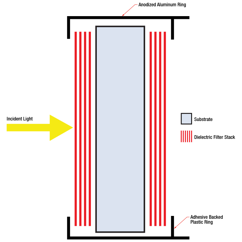
Click to Enlarge
The number of layers shown in this schematic is not indicative of the number of layers in an actual hard-coated bandpass filter. The drawing is also not to scale.
Hard-Coated Bandpass Filter Structure
A bandpass filter is created by depositing layers of material on the surface of the substrate. For our hard-coated bandpass filters, the coating is comprised of dielectric stacks alternating with dielectric spacer layers. Each dielectric stack is composed of a large number of alternating layers of low-index and high-index material. The thickness of each layer in the dielectric stack is λ/4, where λ is the design center wavelength of the bandpass filter (i.e. the wavelength designed to have highest transmittance through the filter at normal incidence). The spacer layers are placed in between the stacks and have a thickness of (nλ)/2, where n is an integer. A Fabry-Perot cavity is formed by each spacer layer sandwiched between dielectric stacks. The filter is mounted in an engraved metal ring for protection and ease of handling.
Filter Operation Overview
The constructive interference conditions of a Fabry-Perot cavity allow light at the center wavelength, and a small band of wavelengths to either side, to be transmitted efficiently, while destructive interference prevents the light outside the passband from being transmitted. However, the band of blocked wavelengths on either side of the center wavelength is small. To increase the blocking range of the filter, materials with broad blocking ranges are used as the substrate or to coat the spacer layers. Although these materials effectively block out-of-band transmission of incident radiation, they also decrease the transmission through the filter in the passband.
Filter Temperature
Click to Enlarge
This plot displays the forward (solid lines) and backward (dashed lines) transmission through the FBH800-10 and FBH800-40 hard-coated bandpass filters.
The center wavelength of the filter can be tuned slightly (~1 nm over the operating range of the filter) by changing the temperature of the filter. This is primarily due to the slight thermal expansion or contraction of the layers.
Filter Orientation
Direction of Transmission
An engraved arrow on the edge of the filter is used to indicate the recommended direction for the transmission of light through the filter. Orienting the coated side toward the source will reduce unwanted scattering and minimize reflections sent back toward the source. Using the filter in the opposite orientation will not, however, significantly affect the performance of the filter. The plot to the right was made by illuminating the filter with a low intensity broadband light and measuring the transmission as a function of wavelength. This plot shows that the direction of transmission through the filter has very little effect on the intensity and the spectrum of the light transmitted through the filter. The minimal variation between the forward and backward traces is most likely due to a small shift in the incident angle of the light on the filter introduced when the filter was removed, flipped over, and replaced in the jig.
Angle of Incidence (AOI)
The filter is intended to be used with collimated light normally incident on the surface of the filter. For uncollimated light or light striking the surface at an angle not normally incident to the surface, the center wavelength (wavelength corresponding to peak transmission) will shift toward lower wavelengths and the shape of the transmission region (passband) will change. Varying the angle of incidence (AOI) by a small amount can be used to effectively tune the passband over a narrow range. Large changes in the incident angle will cause larger shifts in the center wavelength but will also significantly distort the shape of the passband and, more importantly, cause a significant decrease in the transmittance of the passband. The plots below show examples of the change of the passband, transmission, and center wavelength (CWL) with when the AOI is changed for various filters. Filters with passband full width half maxima (FWHM) in the range of 1 nm to 5 nm are particularly susceptible to these shifts and extra care should be taken to ensure they are set to the desired AOI. The plots below given in order of increasing nominal passband FWHM.
Click to Enlarge
This plot displays the changing transmission and FWHM of the passband for an FLH1064-3 hard-coated bandpass filter at varying angles of incidence (AOI). The design CWL and passband of the FLH1064-3 filter are 1064 nm and 3 nm, respectively.
Click to Enlarge
This plot displays the changing transmission and FWHM of the passband for an FLH532-1 hard-coated bandpass filter at varying angles of incidence (AOI). The design CWL and passband of the FLH532-1 filter are 532 nm and 1 nm, respectively.
Click to Enlarge
This plot displays the changing transmission and FWHM of the passband for an FLH1030-10 hard-coated bandpass filter at varying angles of incidence (AOI). The design CWL and passband of the FLH1030-10 filter are 1030 nm and 10 nm, respectively.
Click to Enlarge
This plot displays the changing transmission and FWHM of the passband for an FBH800-10 hard-coated bandpass filter at varying angles of incidence (AOI). The design CWL and passband of the FBH800-10 filter are 800 nm and 10 nm, respectively.
The plots below show how the properties of the FLH532-1, FLH1064-3, and FLH1030-10 hard-coated bandpass filters change as the AOI is varied.
Click to Enlarge
This plot shows the the FWHM at the CWL corresponding to the peak transmission at the given AOI. Item #'s FLH532-1, FLH1064-3, and FLH1030-10 have design center wavelengths of 532, 1064, and 1030 nm with 1, 3, and 10 nm FWHM passbands, respectively.

Click to Enlarge
This plot displays the transmission at the design center wavelength as the angle of incidence is varied. As can be seen in this graph, the transmission of filters with wider passbands are less sensitive to changes in the AOI. Item #'s FLH532-1, FLH1064-3, and FLH1030-10 have design center wavelengths of 532, 1064, and 1030 nm with 1, 3, and 10 nm FWHM passbands, respectively.
Click to Enlarge
This plot displays the center wavelength that provides the maximum transmission for a given angle of incidence for an FLH1030-10 hard-coated bandpass filter with a design CWL of 1030 nm and a passband FWHM of 10 nm.
Click to Enlarge
This plot displays the center wavelength that provides the maximum transmission for a given angle of incidence for an FLH1064-3 hard-coated bandpass filter with a design CWL of 1064 nm and a passband FWHM of 3 nm.
Click to Enlarge
This plot displays the center wavelength and peak transmission at that wavelength for a given angle of incidence for an FLH532-1 hard-coated bandpass filter with design CWL of 532 nm and passband FWHM of 1 nm.
Filter Reflectance
Thorlabs' hard-coated bandpass filters reflect out-of-band light with high efficiency. The plot below shows the measured reflectance of an FBH1200-10 hard-coated bandpass filter with a design CWL of 1200 nm and passband FWHM of 10 nm. The blocking region for this filter is specified as ODabs > 5 between the ranges of 200 - 1180 nm and 1220 - 1700 nm.
Click to Enlarge
This plot displays the reflectance of an FBH1200-10 hard-coated bandpass filter over an extended range from 200 nm to 1800 nm. As can be seen in the graph, the filter reflectance is high within the blocking region of 200 - 1180 nm and 1220 - 1700 nm. The drop in reflectance below 300 nm is due to increased absorption by the glass substrate.
Out-of-Band Filter Performance
The transmission and optical density properties of the hard-coated bandpass filters will vary for far out-of-band wavelengths. The plots below show the variation in transmission and optical density for wavelengths far outside the specified blocking regions of 200 - 379 nm and 401 - 1200 nm for an FBH390-10 hard-coated bandpass filter. The FBH390-10 has a design CWL of 390 nm and a passband FWHM of 10 nm. The blocking region is specified to be ODabs > 5 between the ranges of 200 - 379 nm and 401 - 1200 nm.
Click to Enlarge
This plot displays the optical density (OD) measured between 200 nm and 1600 nm for the FBH390-10 hard-coated bandpass filter. The OD drops off for wavelengths beyond 1200 nm.
Click to Enlarge
This plot displays the transmission through an FBH390-10 hard-coated bandpass filter over an extended range from 200 nm to 1600 nm. The transmission varies for wavelengths beyond 1200 nm.
| Posted Comments: | |
user
(posted 2023-12-24 22:59:25.47) Regarding the central wavelength of narrow filters. The datasheet indicates uncertainty of 0.5% of central wavelength. Can you clarify? We are specifically interested in FBH1550-4
Thank you, jpolaris
(posted 2023-12-26 07:40:56.0) Thank you for contacting Thorlabs. The ±0.5% figure on variability in center-wavelength location is due to part-to-part variation that is inherent to our manufacturing technique. If your application requires a specific value for CWL, we might consider hand-selecting for CWL as a special order at an additional cost. Special requests such as this can be made by contacting us at techsupport@thorlabs.com. I have reached out to you directly to discuss this further. |
| Item #a | Center Wavelengthb (Transmission) |
FWHM Bandwidth |
Blocking Regions (Optical Density) | Transmission Datac |
TWEd | Surface Quality |
Mounted Thickness |
Clear Aperture |
Outer Diameter |
|---|---|---|---|---|---|---|---|---|---|
| FBH700-10 | 700 nm (T > 90%) | 10 nm | 200 - 684 nm, 716 - 1200 nm (ODabs > 5) | ≤158.2 nm | 60-40 Scratch-Dig |
3.5 mm | Ø21.1 mm | Ø25.0 mm | |
| FBH700-40 | 700 nm (T > 90%) | 40 nm | 200 - 669 nm, 730 - 1200 nm (ODabs > 5) | ≤158.2 nm | |||||
| FBH710-10 | 710 nm (T > 90%) | 10 nm | 200 - 694 nm, 725 - 1200 nm (ODabs > 5) | ≤158.2 nm | |||||
| FBH720-10 | 720 nm (T > 90%) | 10 nm | 200 - 704 nm, 735 - 1200 nm (ODabs > 5) | ≤158.2 nm | |||||
| FBH730-10 | 730 nm (T > 90%) | 10 nm | 200 - 714 nm, 746 - 1200 nm (ODabs > 5) | ≤158.2 nm | |||||
| FBH740-10 | 740 nm (T > 90%) | 10 nm | 200 - 724 nm, 756 - 1200 nm (ODabs > 5) | ≤158.2 nm | |||||
| FBH750-10 | 750 nm (T > 90%) | 10 nm | 200 - 733 nm, 766 - 1200 nm (ODabs > 5) | ≤158.2 nm | |||||
| FBH750-40 | 750 nm (T > 90%) | 40 nm | 200 - 718 nm, 781 - 1200 nm (ODabs > 5) | ≤158.2 nm |
- All specifications are valid for AOI = 0°.
- Center wavelength is nominal. The actual center wavelength of the passband may vary from the stated value, although typically within ±0.5%.
- Click on
 for a plot and downloadable data. Please note that transmission is only guaranteed for the specified wavelength and that the data in the plots is typical. Performance may vary from lot to lot.
 - Transmitted wavefront error (RMS) over the clear aperture.
In the table below, the items highlighted in green have passbands with a FWHM of 1 - 5 nm.
| Item #a | Center Wavelengthb (Transmission) |
FWHM Bandwidth |
Blocking Regions (Optical Density) | Transmission Datac |
TWEd | Surface Quality |
Mounted Thickness |
Clear Aperture |
Outer Diameter |
|---|---|---|---|---|---|---|---|---|---|
| FBH760-10 | 760 nm (T > 90%) | 10 nm | 200 - 743 nm, 776 - 1200 nm (ODabs > 5) | ≤158.2 nm | 60-40 Scratch-Dig |
3.5 mm | Ø21.1 mm | Ø25.0 mm | |
| FBH770-10 | 770 nm (T > 90%) | 10 nm | 200 - 754 nm, 787 - 1200 nm (ODabs > 5) | ≤158.2 nm | |||||
| FBH780-3 | 780 nm (T > 90%) | 3 nm | 200 - 764 nm, 796 - 1200 nm (ODabs > 5) | ≤158.2 nm | 60-40 Scratch-Dig |
3.5 mm | Ø21.1 mm | Ø25.0 mm | |
| FBH05780-10 | 780 nm (T > 90%) | 10 nm | 200 - 752 nm, 808 - 1200 nm (ODabs > 5) | λ/2e | 60-40 Scratch-Dig |
3.5 mm | Ø10.0 mm | Ø12.5 mm | |
| FBH780-10 | 780 nm (T > 90%) | 10 nm | 200 - 752 nm, 808 - 1200 nm (ODabs > 5) | λ/2e | 60-40 Scratch-Dig |
3.5 mm | Ø21.1 mm | Ø25.0 mm | |
| FBH785-3 | 785 nm (T > 90%) | 3 nm | 200 - 769 nm, 801 - 1200 nm (ODabs > 5) | ≤158.2 nm | 60-40 Scratch-Dig |
3.5 mm | Ø21.1 mm | Ø25.0 mm | |
| FBH785-10 | 785 nm (T > 90%) | 10 nm | 200 - 766 nm, 804 - 1200 nm (ODabs > 5) | ≤158.2 nm | 60-40 Scratch-Dig |
3.5 mm | Ø21.1 mm | Ø25.0 mm | |
| FBH790-10 | 790 nm (T > 90%) | 10 nm | 200 - 773 nm, 807 - 1200 nm (ODabs > 5) | ≤158.2 nm |
- All specifications are valid for AOI = 0°.
- Center wavelength is nominal. The actual center wavelength of the passband may vary from the stated value, although typically within ±0.5%.
- Click on for a plot and downloadable data. Please note that transmission is only guaranteed for the specified wavelength and that the data in the plots is typical. Performance may vary from lot to lot.
- Transmitted wavefront error (RMS) over the clear aperture.
- At 632.8 nm
In the table below, the items highlighted in green have passbands with a FWHM of 1 - 5 nm.
| Item #a | Center Wavelengthb (Transmission) |
FWHM Bandwidth |
Blocking Regions (Optical Density) | Transmission Datac |
TWEd | Surface Quality |
Mounted Thickness |
Clear Aperture |
Outer Diameter |
|---|---|---|---|---|---|---|---|---|---|
| FBH800-10 | 800 nm (T > 90%) | 10 nm | 200 - 771 nm, 829 - 1200 nm (ODabs > 5) | λ/2e | 60-40 Scratch-Dig |
3.5 mm | Ø21.1 mm | Ø25.0 mm | |
| FBH800-40 | 800 nm (T > 90%) | 40 nm | 200 - 757 nm, 845 - 1200 nm (ODabs > 5) | λ/2e | |||||
| FBH808-3 | 808 nm (T > 90%) | 3 nm | 200 - 791 nm, 825 - 1200 nm (ODabs > 5) | ≤158.2 nm | 60-40 Scratch-Dig |
3.5 mm | Ø21.1 mm | Ø25.0 mm | |
| FBH810-10 | 810 nm (T > 90%) | 10 nm | 200 - 781 nm, 839 - 1200 nm (ODabs > 5) | λ/2e | 60-40 Scratch-Dig |
3.5 mm | Ø21.1 mm | Ø25.0 mm | |
| FBH820-10 | 820 nm (T > 90%) | 10 nm | 200 - 803 nm, 837 - 1200 nm (ODabs > 5) | ≤158.2 nm | |||||
| FBH830-10 | 830 nm (T > 90%) | 10 nm | 200 - 812 nm, 847 - 1200 nm (ODabs > 5) | ≤158.2 nm | |||||
| FBH840-10 | 840 nm (T > 90%) | 10 nm | 200 - 822 nm, 857 - 1200 nm (ODabs > 5) | ≤158.2 nm |
- All specifications are valid for AOI = 0°.
- Center wavelength is nominal. The actual center wavelength of the passband may vary from the stated value, although typically within ±0.5%.
- Click on for a plot and downloadable data. Please note that transmission is only guaranteed for the specified wavelength and that the data in the plots is typical. Performance may vary from lot to lot.
- Transmitted wavefront error (RMS) over the clear aperture.
- At 632.8 nm
In the table below, the items highlighted in green have passbands with a FWHM of 1 - 5 nm.
| Item #a | Center Wavelengthb (Transmission) |
FWHM Bandwidth |
Blocking Regions (Optical Density) | Transmission Datac |
TWEd | Surface Quality |
Mounted Thickness |
Clear Aperture |
Outer Diameter |
|---|---|---|---|---|---|---|---|---|---|
| FBH05850-10 | 850 nm (T > 90%) | 10 nm | 200 - 832 nm, 868 - 1200 nm (ODabs > 5) | ≤158.2 nm | 60-40 Scratch-Dig |
3.5 mm | Ø10.0 mm | Ø12.5 mm | |
| FBH850-10 | 850 nm (T > 90%) | 10 nm | 200 - 830 nm, 870 - 1200 nm (ODabs > 5) | ≤158.2 nm | 60-40 Scratch-Dig |
3.5 mm | Ø21.1 mm | Ø25.0 mm | |
| FBH850-40 | 850 nm (T > 90%) | 40 nm | 200 - 805 nm, 896 - 1200 nm (ODabs > 5) | ≤158.2 nm | |||||
| FBH852-3 | 852 nm (T > 90%) | 3 nm | 200 - 835 nm, 869 - 1200 nm (ODabs > 5) | ≤158.2 nm | 60-40 Scratch-Dig |
3.5 mm | Ø21.1 mm | Ø25.0 mm | |
| FBH860-10 | 860 nm (T > 90%) | 10 nm | 200 - 842 nm, 878 - 1200 nm (ODabs > 5) | ≤158.2 nm | 60-40 Scratch-Dig |
3.5 mm | Ø21.1 mm | Ø25.0 mm | |
| FBH870-10 | 870 nm (T > 90%) | 10 nm | 200 - 852 nm, 888 - 1200 nm (ODabs > 5) | ≤158.2 nm | |||||
| FBH880-10 | 880 nm (T > 90%) | 10 nm | 200 - 862 nm, 898 - 1200 nm (ODabs > 5) | ≤158.2 nm | |||||
| FBH880-40 | 880 nm (T > 90%) | 40 nm | 200 - 847 nm, 913 - 1200 nm (ODabs > 5) | ≤158.2 nm | |||||
| FBH880-70 | 880 nm (T > 90%) | 70 nm | 200 - 832 nm, 928 - 1200 nm (ODabs > 5) | ≤158.2 nm | |||||
| FBH890-10 | 890 nm (T > 90%) | 10 nm | 200 - 871 nm, 908 - 1200 nm (ODabs > 5) | ≤158.2 nm |
- All specifications are valid for AOI = 0°.
- Center wavelength is nominal. The actual center wavelength of the passband may vary from the stated value, although typically within ±0.5%.
- Click on for a plot and downloadable data. Please note that transmission is only guaranteed for the specified wavelength and that the data in the plots is typical. Performance may vary from lot to lot.
- Transmitted wavefront error (RMS) over the clear aperture.
| Item #a | Center Wavelengthb (Transmission) |
FWHM Bandwidth |
Blocking Regions (Optical Density) | Transmission Datac |
TWEd | Surface Quality |
Mounted Thickness |
Clear Aperture |
Outer Diameter |
|---|---|---|---|---|---|---|---|---|---|
| FBH900-10 | 900 nm (T > 90%) | 10 nm | 200 - 881 nm, 918 - 1200 nm (ODabs > 5) | ≤158.2 nm | 60-40 Scratch-Dig |
3.5 mm | Ø21.1 mm | Ø25.0 mm | |
| FBH900-40 | 900 nm (T > 90%) | 40 nm | 200 - 866 nm, 933 - 1200 nm (ODabs > 5) | ≤158.2 nm | |||||
| FBH905-10 | 905 nm (T > 90%) | 10 nm | 200 - 886 nm, 924 - 1200 nm (ODabs > 5) | ≤158.2 nm | |||||
| FBH905-25 | 905 nm (T > 90%) | 25 nm | 200 - 879 nm, 931 - 1200 nm (ODabs > 5) | ≤158.2 nm | |||||
| FBH910-10 | 910 nm (T > 90%) | 10 nm | 200 - 891 nm, 929 - 1200 nm (ODabs > 5) | ≤158.2 nm | |||||
| FBH920-10 | 920 nm (T > 90%) | 10 nm | 200 - 901 nm, 939 - 1200 nm (ODabs > 5) | ≤158.2 nm | |||||
| FBH930-10 | 930 nm (T > 90%) | 10 nm | 200 - 911 nm, 949 - 1200 nm (ODabs > 5) | ≤158.2 nm | |||||
| FBH940-10 | 940 nm (T > 90%) | 10 nm | 200 - 921 nm, 959 - 1200 nm (ODabs > 5) | ≤158.2 nm |
- All specifications are valid for AOI = 0°.
- Center wavelength is nominal. The actual center wavelength of the passband may vary from the stated value, although typically within ±0.5%
- Click on for a plot and downloadable data. Please note that transmission is only guaranteed for the specified wavelength and that the data in the plots is typical. Performance may vary from lot to lot.
- Transmitted wavefront error (RMS) over the clear aperture.
In the table below, the items highlighted in green have passbands with a FWHM of 1 - 5 nm.
| Item #a | Center Wavelengthb (Transmission) |
FWHM Bandwidth |
Blocking Regions (Optical Density) | Transmission Datac |
TWEd | Surface Quality |
Mounted Thickness |
Clear Aperture |
Outer Diameter |
|---|---|---|---|---|---|---|---|---|---|
| FBH950-10 | 950 nm (T > 90%) | 10 nm | 200 - 930 nm, 969 - 1200 nm (ODabs > 5) | ≤158.2 nm | 60-40 Scratch-Dig |
3.5 mm | Ø21.1 mm | Ø25.0 mm | |
| FBH960-10 | 960 nm (T > 90%) | 10 nm | 200 - 940 nm, 979 - 1200 nm (ODabs > 5) | ≤158.2 nm | |||||
| FBH970-10 | 970 nm (T > 90%) | 10 nm | 200 - 950 nm, 990 - 1200 nm (ODabs > 5) | ≤158.2 nm | |||||
| FBH980-3 | 980 nm (T > 90%) | 3 nm | 200 - 960 nm, 1000 - 1200 nm (ODabs > 5) | ≤158.2 nm | 60-40 Scratch-Dig |
3.5 mm | Ø21.1 mm | Ø25.0 mm | |
| FBH980-10 | 980 nm (T > 90%) | 10 nm | 200 - 960 nm, 1000 - 1200 nm (ODabs > 5) | ≤158.2 nm | 60-40 Scratch-Dig |
3.5 mm | Ø21.1 mm | Ø25.0 mm | |
| FBH990-10 | 990 nm (T > 90%) | 10 nm | 200 - 970 nm, 1010 - 1200 nm (ODabs > 5) | ≤158.2 nm |
- All specifications are valid for AOI = 0°.
- Center wavelength is nominal. The actual center wavelength of the passband may vary from the stated value, although typically within ±0.5%
- Click on for a plot and downloadable data. Please note that transmission is only guaranteed for the specified wavelength and that the data in the plots is typical. Performance may vary from lot to lot.
- Transmitted wavefront error (RMS) over the clear aperture.
In the table below, the items highlighted in green have passbands with a FWHM of 1 - 5 nm.
| Item #a | Center Wavelengthb (Transmission) |
FWHM Bandwidth |
Blocking Regions (Optical Density) | Transmission Datac |
TWEd | Surface Quality |
Mounted Thickness |
Clear Aperture |
Outer Diameter |
|---|---|---|---|---|---|---|---|---|---|
| FBH1000-10 | 1000 nm (T > 90%) | 10 nm | 200 - 980 nm, 1020 - 1200 nm (ODabs > 5) | ≤158.2 nm | 60-40 Scratch-Dig |
3.5 mm | Ø21.1 mm | Ø25.0 mm | |
| FLH1030-3 | 1030 nm (T > 90%) | 3 nm | 200 - 1009 nm, 1051 - 1200 nm (ODabs > 5) | ≤158.2 nm | 60-40 Scratch-Dig |
3.5 mm | Ø21.1 mm | Ø25.0 mm | |
| FLH1030-10 | 1030 nm (T > 90%) | 10 nm | 200 - 1010 nm, 1050 - 1200 nm (ODabs > 5) | λ/4e | 60-40 Scratch-Dig |
3.5 mm | Ø21.1 mm | Ø25.0 mm | |
| FBH1050-10 | 1050 nm (T > 90%) | 10 nm | 200 - 1010 nm, 1095 - 1800 nm (ODabs > 5) | ≤158.2 nm | |||||
| FLH051064-3 | 1064 nm (T > 90%) | 3 nm | 200 - 1041 nm, 1087 - 1200 nm (ODabs > 5) | ≤158.2 nm | 60-40 Scratch-Dig |
3.5 mm | Ø10.0 mm | Ø12.5 mm | |
| FLH1064-3 | 1064 nm (T > 90%) | 3 nm | 200 - 1041 nm, 1087 - 1200 nm (ODabs > 5) | ≤158.2 nm | 60-40 Scratch-Dig |
3.5 mm | Ø21.1 mm | Ø25.0 mm | |
| FLH051064-8 | 1064 nm (T > 90%) | 8 nm | 200 - 1039 nm, 1089 - 1200 nm (ODabs > 5) | λ/4f | 60-40 Scratch-Dig |
3.5 mm | Ø10.0 mm | Ø12.5 mm | |
| FLH1064-8 | 1064 nm (T > 90%) | 8 nm | 200 - 1039 nm, 1089 - 1200 nm (ODabs > 5) | λ/4f | 60-40 Scratch-Dig |
3.5 mm | Ø21.1 mm | Ø25.0 mm | |
| FLH1064-10g | 1064 nm (T > 90%) | 10 nm | 200 - 1044 nm, 1084 - 1200 nm (ODabs > 5) | λ/4e |
- All specifications are valid for AOI = 0°.
- Center wavelength is nominal. The actual center wavelength of the passband may vary from the stated value, although typically within ±0.5%.
- Click on for a plot and downloadable data. Please note that transmission is only guaranteed for the specified wavelength and that the data in the plots is typical. Performance may vary from lot to lot.
- Transmitted wavefront error (RMS) over the clear aperture.
- At the center wavelength.
- At 632.8 nm
- Damage Threshold: 2 J/cm2 (1064 nm, 10 ns, 10 Hz, Ø1.020 mm)
| Item #a | Center Wavelengthb (Transmission) |
FWHM Bandwidth |
Blocking Regions (Optical Density) | Transmission Datac |
TWEd | Surface Quality |
Mounted Thickness |
Clear Aperture |
Outer Diameter |
|---|---|---|---|---|---|---|---|---|---|
| FBH1070-10 | 1070 nm (T > 90%) | 10 nm | 200 - 1050 nm, 1090 - 1200 nm (ODabs > 5) | λ/4e | 60-40 Scratch-Dig |
3.5 mm | Ø21.1 mm | Ø25.0 mm | |
| FBH1100-10 | 1100 nm (T > 90%) | 10 nm | 200 - 1064 nm, 1138 - 1800 nm (ODabs > 5) | ≤158.2 nm | |||||
| FBH1150-10 | 1150 nm (T > 90%) | 10 nm | 200 - 1128 nm, 1172 - 1800 nm (ODabs > 5) | ≤158.2 nm | |||||
| FBH1200-10 | 1200 nm (T > 90%) | 10 nm | 200 - 1180 nm, 1220 - 1700 nm (ODabs > 5) | λ/4f | |||||
| FBH1250-10 | 1250 nm (T > 90%) | 10 nm | 200 - 1226 nm, 1274 - 1800 nm (ODabs > 5) | ≤158.2 nm |
- All specifications are valid for AOI = 0°.
- Center wavelength is nominal. The actual center wavelength of the passband may vary from the stated value, although typically within ±0.5%.
- Click on for a plot and downloadable data. Please note that transmission is only guaranteed for the specified wavelength and that the data in the plots is typical. Performance may vary from lot to lot.
- Transmitted wavefront error (RMS) over the clear aperture.
- At 632.8 nm
- At the center wavelength.
| Item #a | Center Wavelengthb (Transmission) |
FWHM Bandwidth |
Blocking Regions (Optical Density) | Transmission Datac |
TWEd | Surface Quality |
Mounted Thickness |
Clear Aperture |
Outer Diameter |
|---|---|---|---|---|---|---|---|---|---|
| FBH1300-12 | 1300 nm (T > 90%) | 12 nm | 200 - 1255 nm, 1345 - 1800 nm (ODabs > 5) | ≤158.2 nm | 60-40 Scratch-Dig |
3.5 mm | Ø21.1 mm | Ø25.0 mm | |
| FBH1300-30 | 1300 nm (T > 90%) | 30 nm | 200 - 1265 nm, 1334 - 1800 nm (ODabs > 5) | ≤158.2 nm | |||||
| FBH1310-12 | 1310 nm (T > 90%) | 12 nm | 200 - 1265 nm, 1345 - 1800 nm (ODabs > 5) | ≤158.2 nm | |||||
| FBH1320-12 | 1320 nm (T > 90%) | 12 nm | 200 - 1294 nm, 1346 - 1800 nm (ODabs > 5) | ≤158.2 nm | |||||
| FBH1330-12 | 1330 nm (T > 90%) | 12 nm | 200 - 1304 nm, 1356 - 1800 nm (ODabs > 5) | ≤158.2 nm | |||||
| FBH1340-12 | 1340 nm (T > 90%) | 12 nm | 200 - 1314 nm, 1366 - 1800 nm (ODabs > 5) | ≤158.2 nm | |||||
| FBH1350-12 | 1350 nm (T > 90%) | 12 nm | 200 - 1324 nm, 1376 - 1800 nm (ODabs > 5) | ≤158.2 nm | |||||
| FBH1400-12 | 1400 nm (T > 90%) | 12 nm | 200 - 1352 nm, 1450 - 1800 nm (ODabs > 5) | ≤158.2 nm | |||||
| FBH1450-12 | 1450 nm (T > 90%) | 12 nm | 200 - 1400 nm, 1500 - 1800 nm (ODabs > 5) | ≤158.2 nm | |||||
| FBH1480-12 | 1480 nm (T > 90%) | 12 nm | 200 - 1452 nm, 1508 - 1800 nm (ODabs > 5) | ≤158.2 nm | |||||
| FBH1490-12 | 1490 nm (T > 90%) | 12 nm | 200 - 1461 nm, 1518 - 1800 nm (ODabs > 5) | ≤158.2 nm |
- All specifications are valid for AOI = 0°.
- Center wavelength is nominal. The actual center wavelength of the passband may vary from the stated value, although typically within ±0.5%
- Click on for a plot and downloadable data. Please note that transmission is only guaranteed for the specified center wavelength and that the data in the plots is typical. Performance may vary from lot to lot.
- Transmitted wavefront error (RMS) over the clear aperture.
In the table below, the items highlighted in green have passbands with a FWHM of 1 - 5 nm.
| Item #a | Center Wavelengthb (Transmission) |
FWHM Bandwidth |
Blocking Regions (Optical Density) | Transmission Datac |
TWEd | Surface Quality |
Mounted Thickness |
Clear Aperture |
Outer Diameter |
|---|---|---|---|---|---|---|---|---|---|
| FBH1500-12 | 1500 nm (T > 90%) | 12 nm | 200 - 1449 nm, 1551 - 1800 nm (ODabs > 5) | ≤158.2 nm | 60-40 Scratch-Dig |
3.5 mm | Ø21.1 mm | Ø25.0 mm | |
| FBH1510-12 | 1510 nm (T > 90%) | 12 nm | 200 - 1481 nm, 1539 - 1800 nm (ODabs > 5) | ≤158.2 nm | |||||
| FBH1520-12 | 1520 nm (T > 90%) | 12 nm | 200 - 1452 nm, 1508 - 1200 nm (ODabs > 5) | ≤158.2 nm | |||||
| FBH1530-12 | 1530 nm (T > 90%) | 12 nm | 200 - 1501 nm, 1559 - 1800 nm (ODabs > 5) | ≤158.2 nm | |||||
| FBH1540-12 | 1540 nm (T > 90%) | 12 nm | 200 - 1488 nm, 1592 - 1800 nm (ODabs > 5) | ≤158.2 nm | |||||
| FBH1550-4 | 1550 nm (T > 90%) | 4 nm | 200 - 1518 nm, 1582 - 1800 nm (ODabs > 5) | ≤158.2 nm | 60-40 Scratch-Dig |
3.5 mm | Ø21.1 mm | Ø25.0 mm | |
| FBH1550-12 | 1550 nm (T > 90%) | 12 nm | 200 - 1530 nm, 1570 - 1700 nm (ODabs > 5) | λ/4e | 60-40 Scratch-Dig |
3.5 mm | Ø21.1 mm | Ø25.0 mm | |
| FBH1550-30 | 1550 nm (T > 90%) | 30 nm | 200 - 1488 nm, 1612 - 1800 nm (ODabs > 5) | ≤158.2 nm | |||||
| FBH051550-40 | 1550 nm (T > 90%) | 40 nm | 200 - 1483 nm, 1617 - 1800 nm (ODabs > 5) | ≤158.2 nm | 60-40 Scratch-Dig |
3.5 mm | Ø10.0 mm | Ø12.5 mm | |
| FBH1550-40 | 1550 nm (T > 90%) | 40 nm | 200 - 1483 nm, 1617 - 1800 nm (ODabs > 5) | ≤158.2 nm | 60-40 Scratch-Dig |
3.5 mm | Ø21.1 mm | Ø25.0 mm | |
| FBH1560-12 | 1560 nm (T > 90%) | 12 nm | 200 - 1507 nm, 1613 - 1800 nm (ODabs > 5) | ≤158.2 nm | |||||
| FBH1570-12 | 1570 nm (T > 90%) | 12 nm | 200 - 1540 nm, 1599 - 1800 nm (ODabs > 5) | ≤158.2 nm | |||||
| FBH1580-12 | 1580 nm (T > 90%) | 12 nm | 200 - 1550 nm, 1610 - 1800 nm (ODabs > 5) | ≤158.2 nm | |||||
| FBH1590-12 | 1590 nm (T > 90%) | 12 nm | 200 - 1560 nm, 1620 - 1800 nm (ODabs > 5) | ≤158.2 nm |
- All specifications are valid for AOI = 0°.
- Center wavelength is nominal. The actual center wavelength of the passband may vary from the stated value, although typically within ±0.5%
- Click on for a plot and downloadable data. Please note that transmission is only guaranteed for the specified wavelength and that the data in the plots is typical. Performance may vary from lot to lot.
- Transmitted wavefront error (RMS) over the clear aperture.
- At the center wavelength.
| Item #a | Center Wavelengthb (Transmission) |
FWHM Bandwidth |
Blocking Regions (Optical Density) | Transmission Datac |
TWEd | Surface Quality |
Mounted Thickness |
Clear Aperture |
Outer Diameter |
|---|---|---|---|---|---|---|---|---|---|
| FBH1600-12 | 1600 nm (T > 90%) | 12 nm | 200 - 1550 nm, 1652 - 1800 nm (ODabs > 5) | ≤158.2 nm | 60-40 Scratch-Dig |
3.5 mm | Ø21.1 mm | Ø25.0 mm | |
| FBH1610-12 | 1610 nm (T > 90%) | 12 nm | 200 - 1580 nm, 1640 - 1800 nm (ODabs > 5) | ≤158.2 nm | |||||
| FBH1620-12 | 1620 nm (T > 90%) | 12 nm | 200 - 1590 nm, 1650 - 1800 nm (ODabs > 5) | ≤158.2 nm | |||||
| FBH1650-12 | 1650 nm (T > 90%) | 12 nm | 200 - 1594 nm, 1706 - 1800 nm (ODabs > 5) | ≤158.2 nm | |||||
| FBH2000-12 | 2000 nm (T > 90%) | 12 nm | 770 - 1960 nm, 2040 - 2700 nm (ODabs > 4) | ≤158.2 nm |
- All specifications are valid for AOI = 0°.
- Center wavelength is nominal. The actual center wavelength of the passband may vary from the stated value, although typically within ±0.5%
- Click on for a plot and downloadable data. Please note that transmission is only guaranteed for the specified wavelength and that the data in the plots is typical. Performance may vary from lot to lot.
- Transmitted wavefront error (RMS) over the clear aperture.

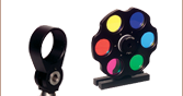
 Zoom
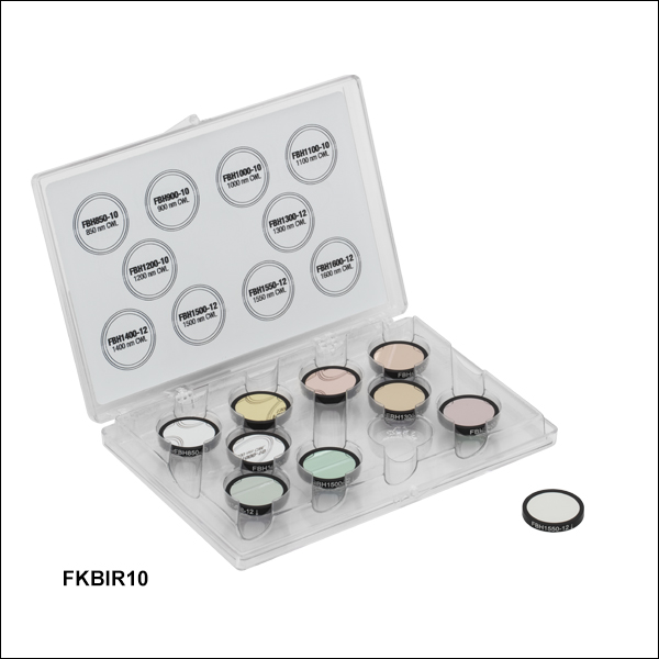
ZoomThorlabs' Bandpass Filter Kits contain 10 mounted hard-coated bandpass filters that can be used to transmit well-defined wavelength bands in the VIS/NIR or NIR, while rejecting other unwanted radiation. Each filter is mounted in an unthreaded Ø25.0 mm black-anodized aluminum ring that can be placed into our selection of Ø1" lens tubes and filter mounts using retaining rings. The filter kits come in a convenient plastic box for storage and transportation purposes. Expand the tables below for more information on the individual filters contained in each kit.
| FKBV10: 351 - 800 nm CWLs, 10 nm FWHM |
|---|
| FKBV40: 400 - 850 nm CWLs, 40 nm FWHM |
|---|
| FKBIR10: 850 - 1600 nm CWLs, 10 - 12 nm FWHM |
|---|
- All specifications are valid for AOI = 0°.
- Transmission at Center Wavelength
- Click on for a plot and downloadable data. Please note that transmission is only guaranteed for the specified wavelength and that the data in the plots is typical. Performance may vary from lot to lot.