 Products Home / Fiber Fusion Splicers and Processing Equipment / Connector Preparation / Laser Cleaver
Laser Cleaver

- CO2 Laser for Clean Fiber Stub Removal
- Cut Glass Fibers Up to Ø1.5 mm
- Consistent Cut Height
- Less Than 8 s Cut Time for >600 µm Clad Fiber
Ferrule Positioning with Guide Lines
After Cutting Process
LCM10


Please Wait

Click to Enlarge
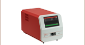
A close-up of the front panel on the LCM10 laser cleaver. Settings and operation are controlled entirely through the touchscreen. Cutting can also be started using the start button on the front or via the FS10 foot switch (sold separately below).
Manual vs. Laser Fiber Cleavers
Manual fiber cleavers result in a flat surface that is best suited for applications where two pieces of fiber will be fused. For applications such as patch cable manufacturing which require a connector to be attached to the fiber, further processing of the fiber end is necessary to achieve the surface polish and radius of curvature needed. The cut surface typically requires polishing with four different sizes of grit starting with a coarse polish to remove any remaining nub as well as epoxy. Using a laser cleaver instead of a manual cleaver to make the initial cut results in a cleaner and more uniform starting surface. This can reduce the needed number of polishing steps and prevent cracking in large fibers. Further polishing is still required to produce a completed fiber; use of a laser cleaver like the LCM10 unit sold below makes the process more efficient.
Demo Unit Available
Interested in trying the LCM10 Laser Cleaverfor your application? Contact us at techsales@thorlabs.com to request a demo unit.
| Key Specificationsa | |
|---|---|
| Laser Wavelength | 10.6 µm |
| Laser Output Power | 40 W (Max) |
| Maximum Fiber Size | Ø1.5 mm |
| Cut Time, Fiber Diameter ≤ 600 µm | <4 seconds |
| Cut Time, Fiber Diameter > 600 µm | <8 seconds |
| Dimensions (L x W x H) | 23.11" x 18.25" x 9.95" (586.9 mm x 463.6 mm x 252.7 mm) |
| Weight | 46.8 lbs (21 kg) |
| Packaged Weight | 64.8 lbs (29 kg) |
Features
- CO2 Laser Beam for Cutting Glass Fibers Up to Ø1500 µm
and Epoxy Beads Up to Ø3 mm- Supported Connectors: FC/PC, SC, SMA, MT, and LC
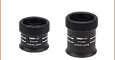
- Supported Ferrules: Ø1.25 mm and Ø2.5 mm
- Automatic Loading Dock and Adjustable Cut Height
- Touchscreen Controls Process and Offers Two Modes:
- Engineering Mode with Access to Cutting Parameters
- Operator Mode with Reduced Access
- Laser Lockout Key and Discard Tray Interlock
- Easy-to-Access Discard Chamber with Off-Cut Bin
- Fume Extraction and Filtration
- USB Port for Downloading Files
- HDMI*-Compatible Output Port for Optional External Monitor
- Ethernet Port for Remote Diagnostics
- Optional Foot Switch
The LCM10 Laser Cleaver is designed for cutting glass fibers in ferrules with a high degree of accuracy, ease of use, and versatility in manufacturing or research environments. It can cut through glass fibers emerging from ferrules as well as through epoxy beads at the ends of ferrules. The largest glass fiber that can be cut is Ø1.5 mm; there is no lower size limit.
This laser cleaver is designed to replace the manual cleave, denubbing, and epoxy removal steps normally employed by patch cord manufacturers with one single, rapid process, thereby reducing user fatigue, operator training times, and scrap rates. The final polishing procedure can be executed in fewer steps than would be necessary with a manual cleave.
This 23.11" x 18.25" x 9.95", 46.8 lbs laser cleaver employs a 40 W CO2 laser to perform the cut and has a fan at the back of the unit that expels the fumes generated by the process away from the user. The exhaust gas is passed through a carbon filter, which filters out the harmful waste products of the cutting process. Off-cuts drop into a collection bin, which is easily accessed via a door in the front of the unit.
The terminated fiber can be cleaned and polished with our line of fiber polishing supplies and fiber cleaning products. The fiber end faces can be checked with either our all-in-one interferometer or portable interferometer.
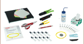
Connectors & Accessories
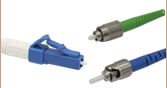
The LCM10 laser cleaver includes a variety of different interchangeable connector mounts, enabling it to trim the fiber emerging from FC/PC, SC, SMA, LC, and MT connectors, as well as Ø1.25 mm and Ø2.5 mm cannulae. We also offer replacement carbon filters and a foot switch (not included) for starting the cutting process.
*HDMI is a trademark or registered trademark of HDMI Licensing Administrator, Inc. The use of such trademark by Thorlabs does not constitute or imply any affiliation with or endorsement or sponsorship by such trademark owner.
LCM10 Laser Cleaver
- Laser Cleaver
- FC/PC and SC Connector Mount (Shown Installed)
- MT Connector Mount
- SMA Connector Mount
- LC Connector Mount
- Ø1.25 mm Cannula Stop
- Ø2.5 mm Cannula Stop
- Discard Bin
- Toolbox
- Fiber Coil Hanger
- Ferrule Holder Mast
- Calibration Pin
- Power Cable

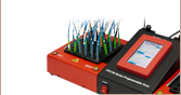
Click to Enlarge
Components included with the LCM10 Laser Cutter are shown above.
Laser Safety and Classification
Safe practices and proper usage of safety equipment should be taken into consideration when operating lasers. The eye is susceptible to injury, even from very low levels of laser light. Thorlabs offers a range of laser safety accessories that can be used to reduce the risk of accidents or injuries. Laser emission in the visible and near infrared spectral ranges has the greatest potential for retinal injury, as the cornea and lens are transparent to those wavelengths, and the lens can focus the laser energy onto the retina.
 |
 |
 |
 |
 |
 |
 |
 |
 |
Safe Practices and Light Safety Accessories
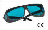
- Laser safety eyewear must be worn whenever working with Class 3 or 4 lasers.
- Regardless of laser class, Thorlabs recommends the use of laser safety eyewear whenever working with laser beams with non-negligible powers, since metallic tools such as screwdrivers can accidentally redirect a beam.
- Laser goggles designed for specific wavelengths should be clearly available near laser setups to protect the wearer from unintentional laser reflections.
- Goggles are marked with the wavelength range over which protection is afforded and the minimum optical density within that range.
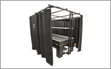
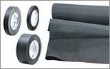
- Laser Safety Curtains and Laser Safety Fabric shield other parts of the lab from high energy lasers.
- Blackout Materials can prevent direct or reflected light from leaving the experimental setup area.
- Thorlabs' Enclosure Systems can be used to contain optical setups to isolate or minimize laser hazards.
- A fiber-pigtailed laser should always be turned off before connecting it to or disconnecting it from another fiber, especially when the laser is at power levels above 10 mW.
- All beams should be terminated at the edge of the table, and laboratory doors should be closed whenever a laser is in use.
- Do not place laser beams at eye level.
- Carry out experiments on an optical table such that all laser beams travel horizontally.
- Remove unnecessary reflective items such as reflective jewelry (e.g., rings, watches, etc.) while working near the beam path.
- Be aware that lenses and other optical devices may reflect a portion of the incident beam from the front or rear surface.
- Operate a laser at the minimum power necessary for any operation.
- If possible, reduce the output power of a laser during alignment procedures.
- Use beam shutters and filters to reduce the beam power.
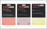
- Post appropriate warning signs or labels near laser setups or rooms.
- Use a laser sign with a lightbox if operating Class 3R or 4 lasers (i.e., lasers requiring the use of a safety interlock).
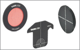
- Do not use Laser Viewing Cards in place of a proper Beam Trap.
Laser Classification
Lasers are categorized into different classes according to their ability to cause eye and other damage. The International Electrotechnical Commission (IEC) is a global organization that prepares and publishes international standards for all electrical, electronic, and related technologies. The IEC document 60825-1 outlines the safety of laser products. A description of each class of laser is given below:
| Class | Description | Warning Label |
|---|---|---|
| 1 | This class of laser is safe under all conditions of normal use, including use with optical instruments for intrabeam viewing. Lasers in this class do not emit radiation at levels that may cause injury during normal operation, and therefore the maximum permissible exposure (MPE) cannot be exceeded. Class 1 lasers can also include enclosed, high-power lasers where exposure to the radiation is not possible without opening or shutting down the laser. |  |
| 1M | Class 1M lasers are safe except when used in conjunction with optical components such as telescopes and microscopes. Lasers belonging to this class emit large-diameter or divergent beams, and the MPE cannot normally be exceeded unless focusing or imaging optics are used to narrow the beam. However, if the beam is refocused, the hazard may be increased and the class may be changed accordingly. |  |
| 2 | Class 2 lasers, which are limited to 1 mW of visible continuous-wave radiation, are safe because the blink reflex will limit the exposure in the eye to 0.25 seconds. This category only applies to visible radiation (400 - 700 nm). |  |
| 2M | Because of the blink reflex, this class of laser is classified as safe as long as the beam is not viewed through optical instruments. This laser class also applies to larger-diameter or diverging laser beams. |  |
| 3R | Class 3R lasers produce visible and invisible light that is hazardous under direct and specular-reflection viewing conditions. Eye injuries may occur if you directly view the beam, especially when using optical instruments. Lasers in this class are considered safe as long as they are handled with restricted beam viewing. The MPE can be exceeded with this class of laser; however, this presents a low risk level to injury. Visible, continuous-wave lasers in this class are limited to 5 mW of output power. |  |
| 3B | Class 3B lasers are hazardous to the eye if exposed directly. Diffuse reflections are usually not harmful, but may be when using higher-power Class 3B lasers. Safe handling of devices in this class includes wearing protective eyewear where direct viewing of the laser beam may occur. Lasers of this class must be equipped with a key switch and a safety interlock; moreover, laser safety signs should be used, such that the laser cannot be used without the safety light turning on. Laser products with power output near the upper range of Class 3B may also cause skin burns. |  |
| 4 | This class of laser may cause damage to the skin, and also to the eye, even from the viewing of diffuse reflections. These hazards may also apply to indirect or non-specular reflections of the beam, even from apparently matte surfaces. Great care must be taken when handling these lasers. They also represent a fire risk, because they may ignite combustible material. Class 4 lasers must be equipped with a key switch and a safety interlock. |  |
| All class 2 lasers (and higher) must display, in addition to the corresponding sign above, this triangular warning sign. |  |
|
Thorlabs Vytran USA
|
.jpg)

| Posted Comments: | |
| No Comments Posted |

 Zoom
ZoomComponents
Included
- Laser Cleaver
- FC/PC and SC Connector Mount
- SMA Connector Mount
- MT Connector Mount
- LC Connector Mount
- Ø1.25 mm Cannula Stop for LC Connector Mount
- Ø2.5 mm Cannula Stop for FC/PC & SC Connector Mount
- Discard Bin
- Toolbox
- Fiber Coil Hanger
- Ferrule Holder Mast
- Calibration Pin
- Power Cable
Optional Accessories (Sold Separately)
- Cut Glass Fibers Up to Ø1500 µm and Epoxy Beads Up to Ø3 mm
- Includes FC/PC, SC, SMA, MT, and LC Connector Mounts
- Includes Two Cannula Stops:
- Ø1.25 mm Cannula Stop for LC Connector Mount
- Ø2.5 mm Cannula Stop for FC/PC & SC Connector Mount
- CO2 Laser Cleaver with Touchscreen Control
- Ethernet Connectivity for Diagnostics
Click to Enlarge
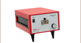
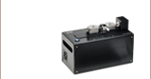
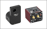
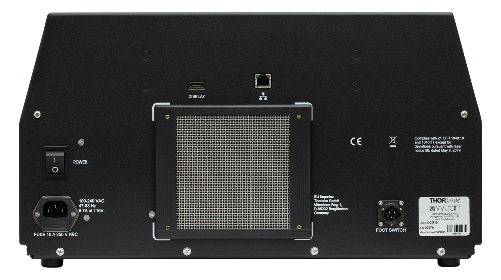
Rear Panel
The LCM10 Laser Cleaver employs a CO2 laser to cut glass fibers emerging from ferrules as well as through epoxy beads at the ends of ferrules, replacing the traditional multi-step cleaving process with one simple procedure. Within a production environment, the use of a fiber cutter reduces user fatigue, operator training, and scrap rates.
The cleaver includes a preinstalled connector mount for FC/PC and SC connectors. The system ships with an additional SMA connector mount, MT connector mount, and LC connector mount. These mounts attach to the recessed loading dock using a thumbscrew; the dock may be raised via the touchscreen interface to make mounting and removal easier. A Ø1.25 mm cannula stop and Ø2.5 mm cannula stop for the LC and FC/PC & SC mount, respectively, are also included. An off-cut bin in the front discard chamber collects cut remnants, making the clean-up process easier. Emissions from the cutting process are directed to the rear of the unit, where they are expelled through a carbon filter. Each unit is shipped with a location-specific power cord.
Visible on the rear panel shown to the left are the power switch and connector, ethernet port for remote diagnostics, video output port compatible with HDMI connectors for remote camera viewing, the foot switch connector (foot switch available separately below), and the carbon air filter door.
Replacement filters and a foot switch for initiating the cutting procedure are available separately below.

 Zoom
Zoom
Click to Enlarge
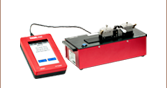
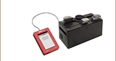
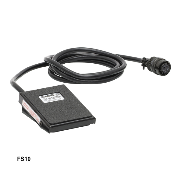
Connecting the Foot Switch
The FS10 Foot Switch can be used to initiate the cutting process instead of the start button at the top of the LCM10 laser cleaver. This is useful if the operator's hands are occupied. The foot switch's 6 foot cable connects to the rear panel of the laser cleaver.

 Zoom
Zoom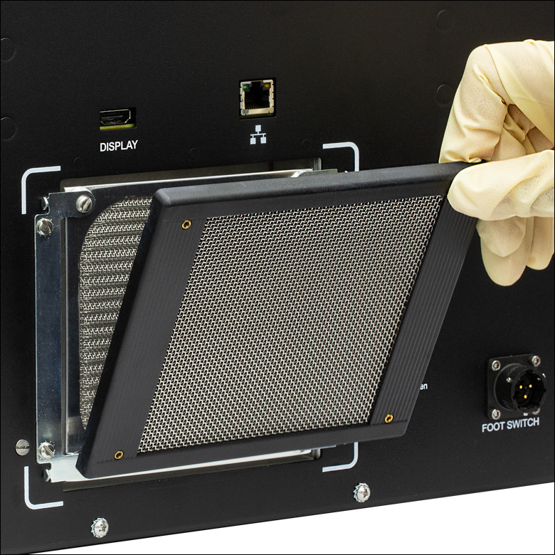
Click to Enlarge
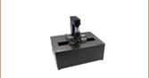
Replacing the Carbon Air Filter
Thorlabs offers replacement carbon air filters for the LCM10 laser cleaver in packages of four (Item # LCM10CF). The filter is held in place by a plastic cage that can be removed by prying an edge with a fingernail or flathead screwdriver. After replacing the filter, the cage can be snapped back onto the cleaver. We recommend replacing the filter every 6 months.