 Products Home / Optomechanical Components / Optomechanical Mounts / Optical Mirror Mounts / Polaris® Mirror Mounts / Low-Distortion Polaris® Mirror Mounts / Polaris® Low-Distortion Kinematic Mirror Mounts for Ø6" Optics
Polaris® Low-Distortion Kinematic Mirror Mounts for Ø6" Optics

- Full Cage Retention of the Optic
- Three Point Contact Base Provides Ultra-Stable Mounting
- Patent Pending Polished Sapphire and Stainless Steel Movement
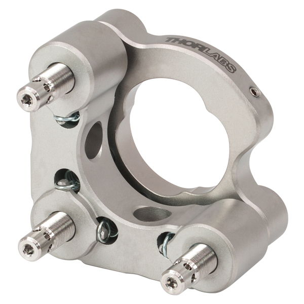
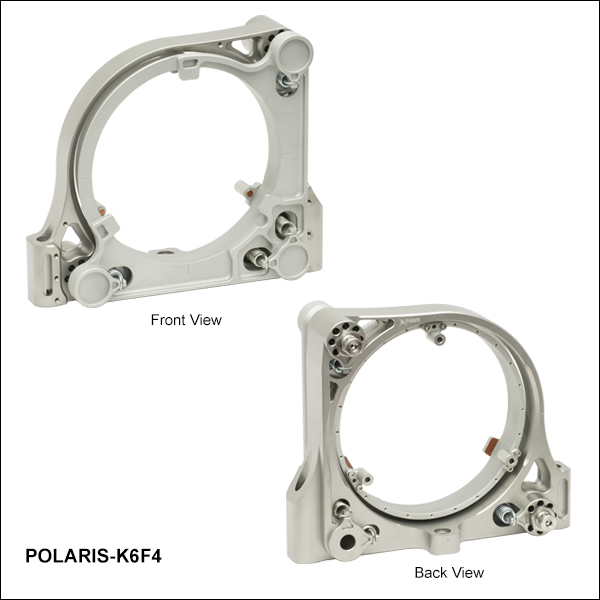
POLARIS-K6F4
Low-Distortion
Ruggedized Optic Mount
2 Hex Adjusters
Application Idea


Please Wait
Click for Details
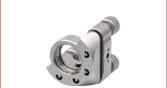
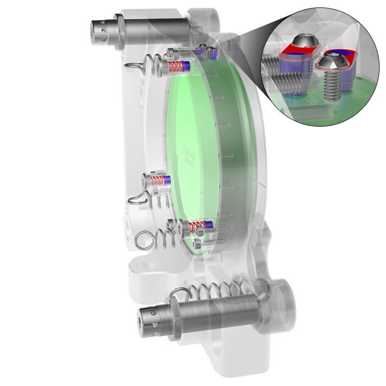
Figure 1.1 POLARIS-K4F4 Ø4" mirror mount cutaway diagram. The optic retention pistons (located behind the optic) and side contact pistons (at the top of the mount) have springs and stress-reducing contacts (highlighted red and blue, respectively). The POLARIS-K6F4 Ø6" mirror mount uses the same optic retention mechanisms.
Features
- Machined from Stress-Relieved Stainless Steel with Matched Coefficients of Thermal Expansion (CTE)
- Bi-Metal Design to Achieve Ultra-Stable Beam Pointing Stability (US Patent 11,150,439)
- Spring-Dampened, Indexed, Three-Point-Axial-and-Radial Contact Optic Cell
- Low Optical Distortion Lens Cell (US Patent 9,599,786)
- Hardened Stainless Steel Ball Contacts with Sapphire Seats for Durability and Smooth Movement
- Matched Actuator/Body Pairs Provide Smooth Kinematic Adjustment
- Less than 5 µrad Deviation after Temperature Cycling Guaranteed (See Thermal Test Data Tab for Details)
- Passivated Stainless Steel Surface and Special Pure Metal (Dye Free and Plastics Free) High Temperature Anodizing Ideal for Vacuum and High-Power Laser Cavity Applications
- Low Mount-to-Optic Weight Ratio
- Mass Reduced Lens Cell for Improved Beam Pointing Stability
- Custom Mount Configurations are Available by Contacting Tech Support
The Polaris® Low-Distortion Kinematic Mirror Mount for Ø6" Optics provides long-term pointing stability, while minimizing optic surface distortion introduced by the mount.
Optic Retention
Each mount features a faceplate with three padded contacts and two side contact pistons to mount the optic and reduce optical distortion compared to standard setscrew or retaining ring optic mount designs. Three padded spring-loaded pistons lock the optic in from behind, ensuring the optic is secure against significant thermal shock. See the Low Distortion tab and the Optic Installation tab for more details.
Polaris optic bores are precision machined to achieve a fit that will provide optimum beam pointing stability performance over changing environmental conditions such as temperature changes, transportation shock, and vibration. Each mount is designed to be used with an optic that is within +0"/-0.010" of the specified diameter; using an optic outside of this range will lead to diminished performance. For inquiries about mounts for other optic sizes, please contact Tech Support.
Design
The backplate is machined from heat-treated stainless steel, while the front plate is made from a superalloy aluminum, which has been aged for improved stability. The two-material design securely mounts the optic while also preventing stresses from forming in the optic due to extreme thermal shock. The Polaris ultra-stable design addresses the causes of beam missalignment in systems with extreme temperature fluctuation; please refer to the Design Features tab for detailed information.
Post Mounting
The Polaris Ø6" mirror mount includes three 5/16" (M7) counterbores for mounting; 1/4"-20 or M6 cap screws and washers can be used with these bores to secure the mount to three Ø1" posts. See the Usage Tips tab for more recommendations about mounting configurations.
Cleanroom and Vacuum Compatibility
The POLARIS-K6F4 is designed to be compatible with cleanroom and vacuum applications. See the Specs tab and the Design Features tab for more information.
| Item # | POLARIS-K6F4 |
|---|---|
| Optic Size | Ø6" +0"/-0.010" (Ø152.4 mm +0 mm/-0.25 mm) |
| Optic Thickness | 1.000" ± 0.010" (25.40 mm ± 0.25 mm) |
| Transmissive Clear Aperturea | Ø5.25" (Ø133.35 mm) |
| Number of Adjusters | Two |
| Adjuster Drive | 5 mm Hex Ø0.096" (Ø2.4 mm) Adjuster Side Holes |
| Adjuster Thread | 9/16"-100 (100 TPI Matched Actuator/Body Pairs) |
| Measured Point-to-Point Mechanical Resolution per Adjuster |
5 µrad (Typical); 2 µrad (Achievable) |
| Measured Adjuster Lock Mechanical Resolution per Adjuster |
5 µrad (Typical); 2 µrad (Achievable) |
| Resolution | 2.1 mrad/rev |
| Mechanical Angular Range (Nominal) | ±2° |
| Beam Deviation After Thermal Cyclingb | 5 μrad |
| Mounting | Three 5/16" (M7) Counterbores, Three 1/4" (M6) Screws with Washers Can be Used for Post Mounting |
| Alignment Pin Holesc | Two Ø5 mm Alignment Pin Holes: One at the Left and Right Counterbores |
| Vacuum Compatibilityd | 10-9 Torr at 25 °C with Proper Bake Out 10-5 Torr at 25 °C without Bake Out Grease Vapor Pressure: 10-13 Torr at 20 °C,10-5 Torr at 200 °C Epoxy Meets Low Outgassing Standards NASA ASTM E595 and Telcordia GR-1221 |
| Operating Temperature Range | -30 to 200 °C |
Replacing the Optic in a POLARIS-K6F4 Low-Distortion Mount
The optic and balldrivers shown with the mount in Figures 3.1 through 3.6 are not included with purchase.
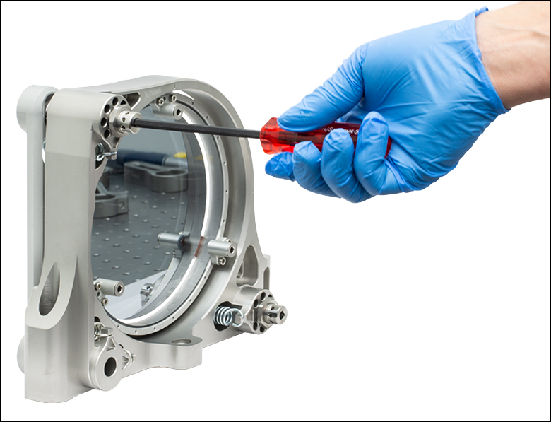
To remove a mounted optic, use a 5 mm balldriver or hex key to turn the Top Adjuster Screw (see Figure 3.1) until the Side Contact Piston Retention Screws are exposed on the top side of the mount (see Figure 3.2). Then, use a 2 mm balldriver or hex key to back off the Side Contact Piston Retention Screws (2 places) by one turn.
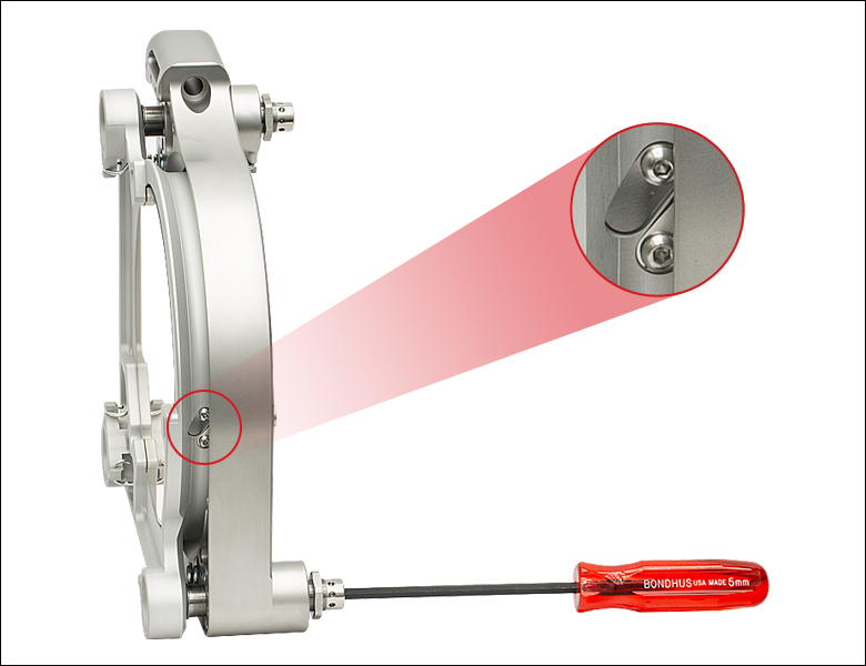
Click to Enlarge
Figure 3.2 The Exposed Side Contact Retention Screws on the Top of the POLARIS-K6F4 Ø6" Mirror Mount
Loosen each Optic Spring Compression Screw (3 places, see Figure 3.3) with a 5 mm balldriver or hex key by two turns, then remove each Optic Piston Array Retention Screw (6 places) with a 2.5 mm balldriver or hex key (see Figure 3.4). This will allow the Optic Retention Pistons (3 places), which make up the Optic Piston Array, to be removed from the mount, opening up the back of the optic bore.
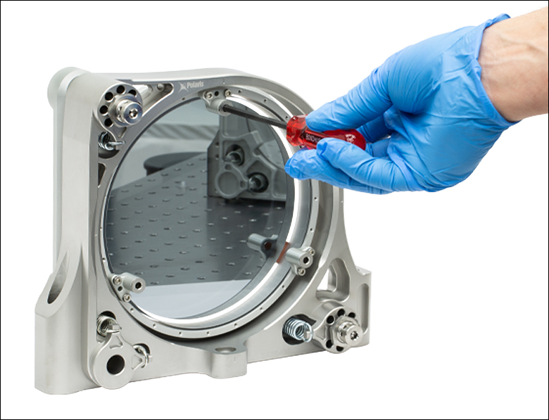
Click to Enlarge
Figure 3.3 Loosening an Spring Compression Screw (3 Places) on the POLARIS-K6F4 Ø6" Mirror Mount
Click to Enlarge
Figure 3.4 Loosening an Optic Piston Array Retention Screw (6 Places) of the POLARIS-K6F4 Ø6" Mirror Mount
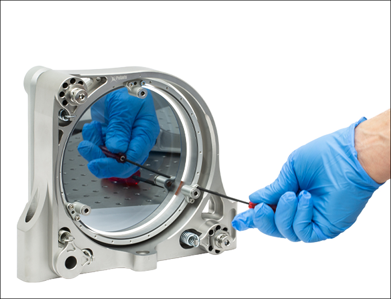
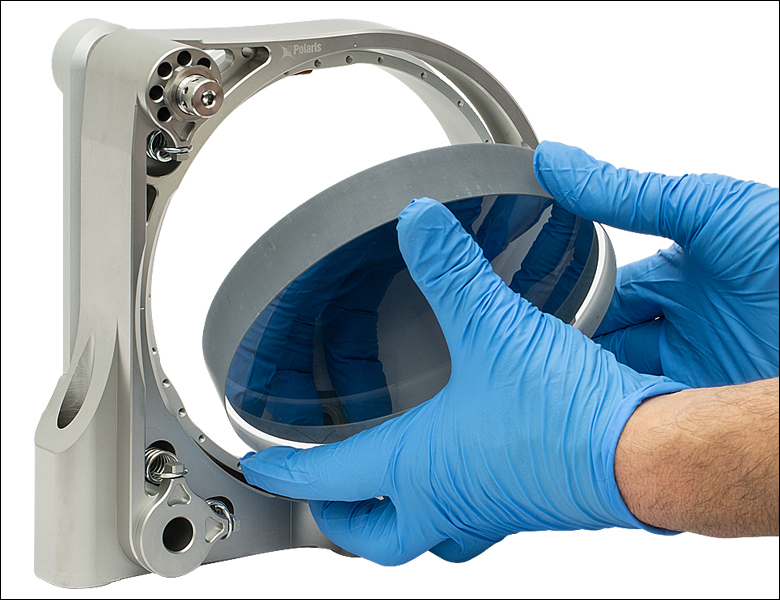
Using two hands, carefully remove the optic from the bore by pushing it through the back (see Figures 3.5 and 3.6).

Click to Enlarge
Figure 3.5 Bracing the Optic when Removing it from the POLARIS-K6F4 Ø6" Mirror Mount
Click to Enlarge
Figure 3.6 Gently Tilting the Optic out of the POLARIS-K6F4 Ø6" Mirror Mount
Before installing a new optic in the mount, ensure that there is no grease, dirt, or dust in the optic bore or on the optic itself. Remove any particulates with clean compressed air and/or clean with ethanol. Then, slowly tilt the new optic in through the opening in the back of the mount, as shown in Figure 3.6. It may help to use one hand to brace the front of the optic while positioning with the other, in a manner similar to what is shown in Figure 3.5, as this can help ensure the optic remains concentric with the optic bore. Retighten the Side Contact Piston Retention Screws with 2.8 lb-in (0.32 N-m) of torque, re-install the Optic Piston Array and Retention Screws using 2.8 lb-in (0.32 N-m) of torque, and tighten each Optic Spring Compression Screw with 30 lb-in (3.4 N-m) of torque.
Note: The force from the Side Contact Piston should secure the optic enough to leave the mount standing up while reattaching the retention springs; however, for a safer position to mount the optic, once the Side Contact Piston Retention Screws have been tightened, tilt the mount downwards until it is flat on the table. From there, reattach the Optic Retention Springs. Do not worry about the safety of the front of the optic; the front of the mount is cushioned and provides clearance, ensuring the front of the optic will not make contact with the work surface.
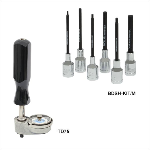
For optic installation, we recommend the BDSH-KIT/M hex driver bit kit with the TD75 torque driver, which are both sold below.
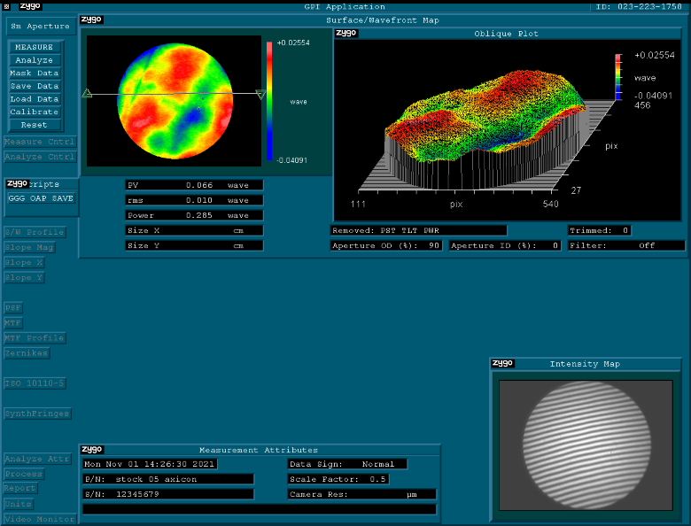
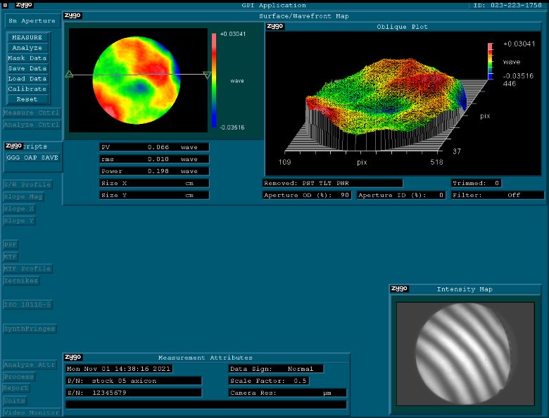
Optical Distortion Testing Using a ZYGO Phase-Shifting Interferometer
Procedure
A Ø6" mirror was installed into a POLARIS-K6F4 Ø6" Polaris Low-Distortion Ruggedized Kinematic Mirror Mount using the procedure detailed in the Optic Installation tab. The mount was then secured to three Ø1" stainless steel posts using three 1/4"-20 cap screws with washers. The Zygo interferometer aperture outer diameter was set to its maximum Ø4" (Ø101.6 mm) for these measurements, and the test wavelength was 634 nm. The Zygo interferometer used for testing was not large enough to scan the entire optic in one measurement, so scans were taken at the left, right, and center of the mounted optic to give an accurate presentation of the performance.
Results
In this test case, the wavefront distortion for the mounted optic was measured to be no greater than 0.094λ (click on the links in Table 4.1 for screenshots of the measurements) and was not noticeably different from the results for the unmounted optic.

Click to Enlarge
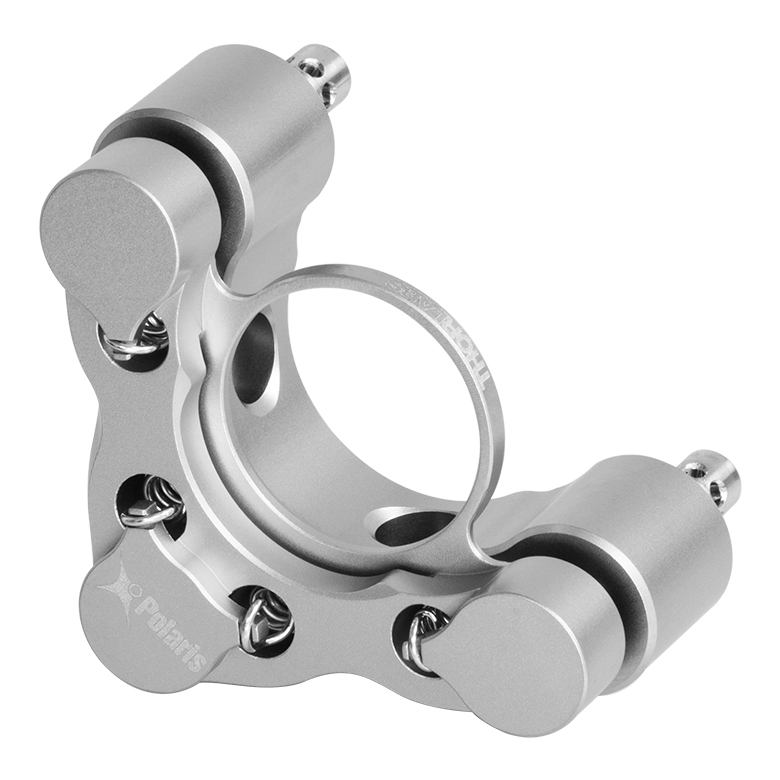
Figure 5.1 Design Features of the POLARIS-K6F4 Low-Distortion Ultra-Stable Mirror Mount
Several common factors typically lead to beam misalignment in an optical setup. These include temperature-induced hysteresis of the mirror's position, crosstalk, drift, and backlash. Polaris mirror mounts are designed specifically to minimize these misalignment factors and thus provide extremely stable performance. Hours of extensive research, multiple design efforts using sophisticated design tools such as finite element analysis software, and months of rigorous testing went into choosing the best components to provide an ideal solution for experiments requiring ultra-stable performance from a kinematic mirror mount.
Thermal Hysteresis
The temperature in most labs is not constant due to factors such as air conditioning, the number of people in the room, and the operating states of equipment. Thus, it is necessary that all mounts used in an alignment-sensitive optical setup be designed to minimize any thermally induced alignment effects. Thermal effects can be minimized by choosing materials with a low coefficient of thermal expansion (CTE), like stainless steel. However, even mounts made from a material with a low CTE do not typically return the mirror to its initial position when the initial temperature is restored. All of the back plate components of the POLARIS-K6F4 mirror mount are heat-treated prior to assembly since this process removes internal stresses that can cause a temperature-dependent hysteresis. As a result, the alignment of the optical system will be restored when the temperature of the mirror mount is returned to the initial temperature.
The method by which the mirror is secured in the mount is another important design factor; the POLARIS-K6F4 mount offers excellent performance without the use of adhesives. Instead, it has a three-point-contact faceplate, two side contact pistons, and three optic retention springs. This design minimizes distortion on the optic surface while maintaining beam pointing stability. Furthermore, the ultra-stable POLARIS-K6F4 low-distortion rugged kinematic mirror mount has a superalloy aluminum front plate which can undergo significant fluctuations in temperature without stressing the optic.
Crosstalk
Crosstalk is minimized by carefully controlling the dimensional tolerances of the front and back plates of the mount so that the pitch and yaw actuators are orthogonal. In addition, sapphire seats are used at all three contact points. Standard metal-to-metal actuator contact points will wear down over time. The polished sapphire seats of the Polaris mounts, in combination with the hardened stainless steel actuator tips, maintain the integrity of the contact surfaces over time.
Click to Enlarge
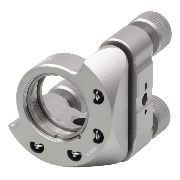
Figure 5.2 The POLARIS-K6F4 Low-Distortion Mount provides clearance for large diameter laser beams over a range of incident angles.
Drift and Backlash
In order to minimize the positional drift of the mirror mount and backlash, it is necessary to limit the amount of play in the adjuster as well as the amount of lubricant used. When an adjustment is made to the actuator, the lubricant will be squeezed out of some spaces and built up in others. This non-equilibrium distribution of lubricant will slowly relax back into an equilibrium state. However, in doing so, this may cause the position of the front plate of the mount to move. The Polaris mounts use adjusters matched to the body that exceed all industry standards so very little adjuster lubricant is needed. These adjusters have a smooth feel that allows the user to make small, repeatable adjustments.
Click for Details
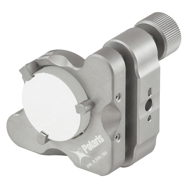
Figure 5.3 The POLARIS-K6F4 Ultra-Stable Low-Distortion Kinematic Mount provides threaded mounting holes for heat sinks and custom payload extensions.
Applications in High-Power Laser Systems
In setups which use high-powered lasers, the utility of expensive optical elements can be difficult to guarantee due to the high thermal energy and large beam diameter of the laser. The POLARIS-K6F4 low-distortion kinematic mirror mount addresses both of these issues through the design of its front plate. The superalloy aluminum, which makes up the front plate, acts as an excellent heat sink, preventing thermal stress on the optic. In the event that the aluminum front plate is insuffient, such as in systems with ultra-high-powered lasers, more heat sinks and heat pipes can be mounted to further protect the optic using the features shown in Figure 5.3. The optic seat has also been designed to support large beam diameters over a range of incident angles (see the Specs tab and Figure 5.2).
Optic Mount Design Minimizes Distortion
The front plate is designed to provide low-distortion mounting of Ø6" optics. In a test involving a Ø6" mirror (see the Low Distortion tab for details), no more than than 0.094λ wavefront distortion was observed on the mounted optic, which was not noticeably different from the distortion measured for the unmounted optic. The low-distortion performance is ideal for imaging applications, as image aberrations that result from the interaction between an optic and the mount will be minimal.
Cleanroom and Vacuum Compatibility
The POLARIS-K6F4 is designed to be compatible with cleanroom and vacuum applications. It is chemically cleaned using the Carpenter AAA passivation method to remove sulfur, iron, and contaminants from the surface. After passivation, it is assembled in a clean environment and then double vacuum bagged to eliminate contamination when transported into a cleanroom.

Click to Enlarge
Figure 5.4 Polaris Mounts are Shipped Inside Two Vacuum Bag Layers
The sapphire contacts are bonded into place using a NASA-approved low outgassing procedure. In addition, DuPont LVP High-Vacuum (Krytox) Grease, an ultra-high vacuum compatible, low outgassing PTFE grease, is applied to the adjusters. These features provide high vacuum compatibility and low outgassing performance. When operating at pressures below 10-5 Torr, we highly recommend using an appropriate bake out procedure prior to installing the mount in order to minimize contamination caused by outgassing.
Cleanroom-Compatible Packaging
Each vacuum-compatible Polaris mount is packaged within two vacuum bag layers after assembly in a clean environment, as seen in Figure 5.4. The vacuum-tight fit of the bags stabilizes the mount, limiting translation of the front plate due to shocks during transportation. The tight fit also minimizes rubbing against the bag, preventing the introduction of bag material shavings that would contaminate the clean mount.
In the vacuum-sealing process, moisture-containing air is drawn out of the packaging. This eliminates unwanted reactions on the surface of the mount without the need for desiccant materials. The vacuum bags protect the mount from contamination by air or dust during transport and storage, and the double-vacuum bag configuration allows for a straightforward and effective cleanroom entry procedure. The outer bag can be removed outside of the cleanroom, allowing the contaminant-free inner bag to be placed into a clean container and transferred into the cleanroom while retaining the benefits of vacuum-bag packaging. Inside the cleanroom, the mount can be removed from the inner bag when ready for use.
Click to Enlarge
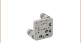
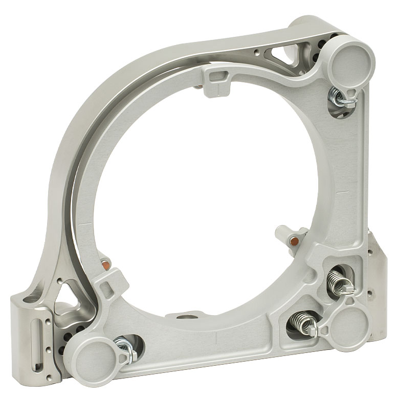
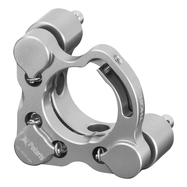
Figure 6.1 Low-Distortion Ultra-Stable Mount for Ø6" Optics
Polaris® Low-Distortion Ultra-Stable Kinematic Mirror Mounts, such as the one shown in Figure 6.1, are specifically designed to provide excellent performance under thermal changes and vibrations. Below are some usage tips to ensure that the POLARIS-K6F4 Low-Distortion Mount for Ø6" Optics provides optimal performance.
Match Materials
Due to its relatively low coefficient of thermal expansion, stainless steel was chosen as the material from which to fabricate the back plate of the POLARIS-K6F4 ultra-stable, low-distortion ruggedized mount. For the front plate, an aged superalloy aluminum was chosen, which reduces the stresses placed on an optic from extreme temperature fluctuations by acting as a heat sink. When mounting, we recommend using components fabricated from the same stainless steel material as the back plate, such as our Ø1" stainless steel posts.
Mounting Options
In order to minimize the impact of temperature changes and vibrations, we recommend mounting the Polaris ultra-stable low-distortion ruggedized mounts as close to the table's surface as possible and matching materials between the mount and mounting surface. By choosing components fabricated from the same material as the mount itself, all expansions and contractions will occur at the same rate.
For best beam pointing stability, the mount can be affixed directly to the surface of a custom stainless steel breadboard. Alternatively, our Ø1" stainless steel posts and POLARIS-CA1 or POLARIS-SCA1 Clamping Arms can be used to secure the mount an optical table or breadboard with standard imperial or metric hole patterns; 1/4"-20 screws with washers can be used with the mount's 5/16" (M7) counterbores when affixing the mount to optical posts. The POLARIS-SCA1 clamping arms are shorter than POLARIS-CA1 clamping arms, providing a smaller footprint if space constraints are a concern. When securing the mount to an optical post, we recommend applying 75 lb-in (8.5 N-m) of torque, which an be accomplished using our TD75 Torque Driver (available below). Be sure to check that the mounting surface is highly flat, polished, and free of debris or scratches prior to mounting.
Mount Alignment
Although the mount is designed to allow adjustments of up to ±2°, to achieve the best performance, it is recommended that the front plate be kept as parallel as possible to the back plate. This ensures maximum stability by forcing an even thermal expansion of all the adjustment screws, which results in the mounted mirror translating in the Z direction as opposed to rotating during temperature changes.
Temperature Regulation
These ultra-stable low-distorition mounts are designed for use in systems where there are frequent and large variations in temperature. The superalloy aluminum front plate acts as a heat sink, reducing stresses on the optic. While Thorlabs' ultra-stable low-distortion mount has been engineered to counter the issues presented by rapid shifts in temperature, we recommend further optimizing the mount performance in systems involving ultra-high-powered lasers by mounting additional heat pipes, shielding, and thermal sinks. This can be accomplished via the M4 x 0.7 threaded holes (8 places) on the front of the stainless steel back plate and the M2.5 x 0.45 threaded holes (21 places) on the back of the superalloy aluminum front plate. For more information, see the Design Features tab.
Polish and Clean the Points of Contact
We highly recommend that the points of contact between the mount and the posts, as well as the posts and the table, are clean and free of scratches or defects. For best results, we recommend using a polishing stone to clean the table’s surface and a polishing pad for the top and bottom of the posts as well as the bottom of the mount. To clean the mount, we recommend using either ethanol or compressed air.
Inspect and Care for Padded Contacts
Thorlabs' POLARIS-K6F4 Ultra-Stable Low-Distortion Mount utilizes Kapton®† plastic padded contacts when securing the optic. It is critical to inspect the pads to ensure they are not burnt and suitable for cushioning the optics. When burnt, Kapton®† plastic will warp and discolor. In the event that these pads need to be replaced, reach out to Tech Support for replacement sheets.
Not Recommended
We do not recommend taking the adjusters out of the body, as this can introduce contamination to the threading, which can consequently reduce the fine adjustment performance significantly. Also, do not pull the front plate away as it might stretch the springs beyond their operating range or crack the sapphire seats. When cleaning the mount, do not use acetone as it can denature the high-vacuum grease.
Adjuster Lock Nuts
The POLARIS-K6F4 2-Adjuster Mount comes with lock nuts pre-installed. The beam can be held on target with the adjuster screws while the mount's position is secured by tightening the lock nuts. In most setups, the lock nuts can be hand-tightened; however, for long term stability, we recommend tightening with 20 lb-in (2.3 N-m) of torque. Each lock nut is pre-greased with the same ultra-high-vacuum-compatible, low-outgassing PTFE grease as the Polaris mounts and has been tested for adjuster fit.
†Kapton® is a registered trademark of DuPont™ Electronics, Inc.
| Posted Comments: | |
| No Comments Posted |
Thorlabs offers several different general varieties of Polaris mounts, including kinematic side optic retention, SM-threaded, low optic distortion, piezo-actuated, vertical drive, and glue-in optic mounts, a fixed monolithic mirror mount and fixed optic mounts, XY translation mounts, 5-axis kinematic mount, and a kinematic platform mount. Refer to the tables below for our complete line of Polaris mounts, grouped by mount type, optic bore size, and then arranged by optic retention method and adjuster type (or intended application in the case of fixed mounts). We also offer a line of accessories that have been specifically designed for use with our Polaris mounts; these are listed in Table 103G. Note that the tables below list Item # suffixes that omit the "POLARIS" prefix for brevity. Click the photos below for details.
| Table 103A Polaris Mount Optic Retention Methods | |||
|---|---|---|---|
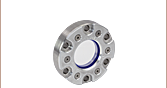
| Side Lock | SM Threaded | Low Distortion | Glue-In |
 |
 |
 |
 |
| Table 103B Polaris Mount Adjuster Types | |||||
|---|---|---|---|---|---|
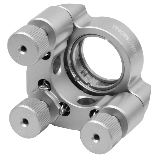
| Side Hole | Hex | Adjuster Knobs | Adjuster Lock Nuts |
Piezo Adjusters | Vertical-Drive Adjusters |
 |
 |
 |
 |
 |
 |
| Table 103C Polaris Kinematic Mounts for Round Optics | ||||
|---|---|---|---|---|
| Optic Retention Method | Side Lock | SM Threaded | Low Distortion | Glue-In |
| Ø1/2" Optics | ||||
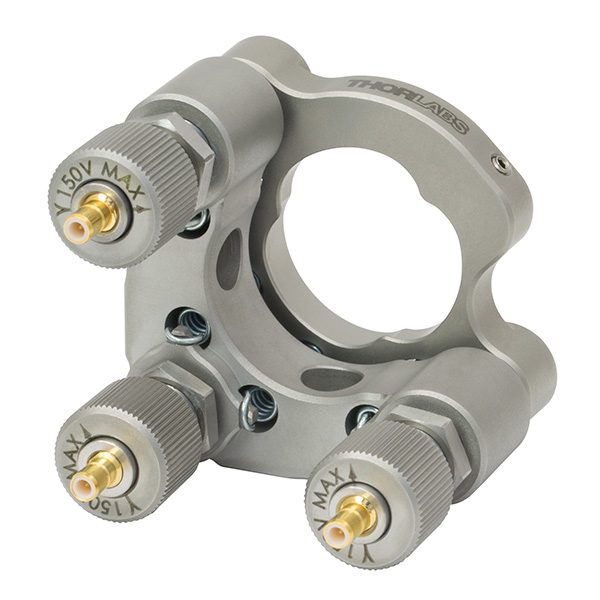
| 2 Side Hole Adjusters | - | - | - | -K05C4 -K05G4 |
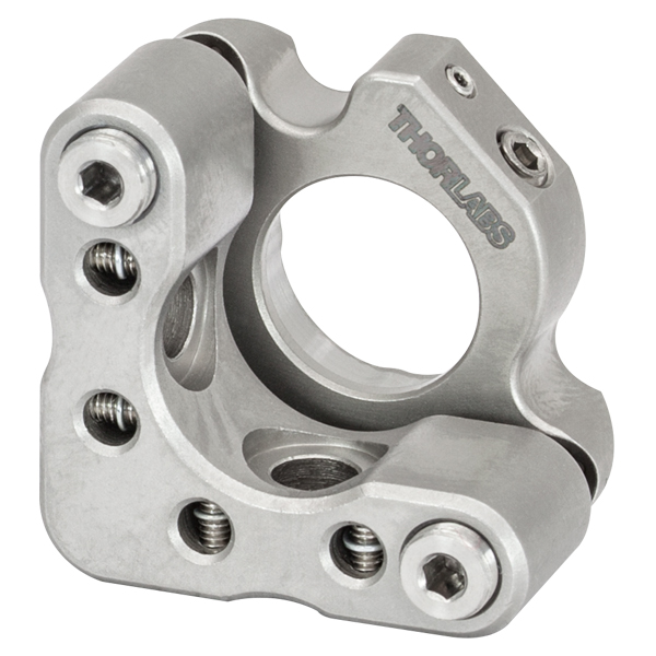
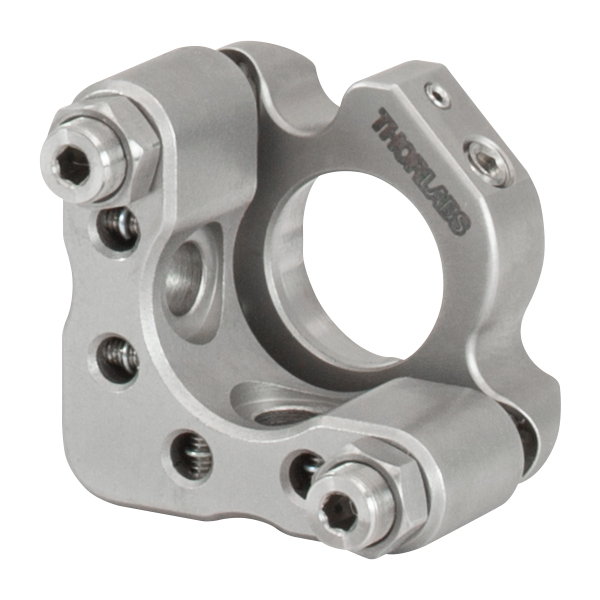
| 2 Hex Adjusters | -K05S1 | -K05T1 | -K05F1 | - |
| 2 Adjusters with Lock Nuts | -K05S2 | -K05T2 | -K05F2 | - |
| 2 Piezoelectric Adjusters | -K05P2 | - | - | - |
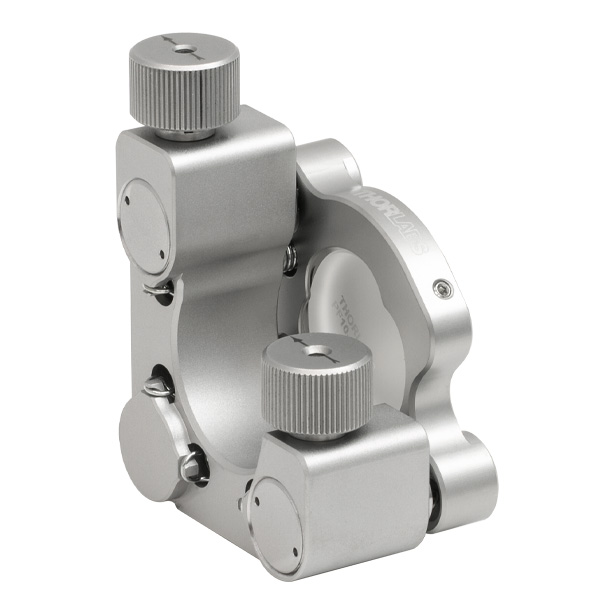
| 2 Vertical Adjusters | -K05VS2 -K05VS2L |
- | - | - |
| 3 Hex Adjusters | -K05 | - | - | - |
| 3 Adjusters with Lock Nuts | - | -K05T6 | -K05F6 | - |
| 3 Adjuster Knobs (Tip/Tilt/Z) & 2 Hex Adjusters (X/Y) |
- | -K05XY | - | - |
| Ø19 mm (3/4") Optics | ||||
| 2 Side Hole Adjusters | -K19S4 | - | -K19F4/M | -K19G4 |
| Ø25 mm Optics | ||||
| 2 Side Hole Adjusters | -K25S4/M | - | -K25F4/M | - |
| Ø1" Optics | ||||
| 2 Side Hole Adjusters | -K1S4 | - | - | -K1C4 -K1G4 |
| 2 Hex Adjusters | -K1E2 -K1-2AH |
-K1T2 | -K1F2 | - |
| 2 Adjuster Knobs | - | -K1T1 | -K1F1 | - |
| 2 Piezoelectric Adjusters | -K1S2P | - | - | - |
| 2 Vertical Adjusters | -K1VS2 -K1VS2L |
- | - | - |
| 3 Side Hole Adjuster | -K1S5 | - | - | - |
| 3 Hex Adjusters | -K1E3 -K1-H |
-K1T3 | - | - |
| 3 Adjuster Knobs | -K1E -K1 |
-K1T | -K1F | - |
| 3 Piezoelectric Adjusters | -K1S3P | - | - | - |
| 3 Adjuster Knobs (Tip/Tilt/Z) & 2 Hex Adjusters (X/Y) |
- | -K1XY | - | - |
| Optic Retention Method | Side Lock | SM Threaded | Low Distortion | Glue-In |
| Ø1.5" Optics | ||||
| 2 Side Hole Adjusters | -K15S4 | - | -K15F4 | - |
| 2 Vertical Adjusters | -K15VS2 -K15VS2L |
- | - | - |
| 3 Adjuster Knobs (Tip/Tilt/Z) & 2 Hex Adjusters (X/Y) |
- | -K15XY | - | - |
| Ø50 mm Optics | ||||
| 2 Side Hole Adjusters | -K50S4/M | - | -K50F4/M | - |
| Ø2" Optics | ||||
| 2 Hex Adjusters | -K2S2 | -K2T2 | -K2F2 | - |
| 2 Adjuster Knobs | -K2S1 | -K2T1 | -K2F1 | - |
| 2 Piezoelectric Adjusters | -K2S2P | - | - | - |
| 2 Vertical Adjusters | -K2VS2 -K2VS2L |
- | - | - |
| 3 Hex Adjusters | -K2S3 | -K2T3 | -K2F3 | - |
| 3 Adjuster Knobs | -K2 | -K2T | -K2F | - |
| Ø3" Optics | ||||
| 2 Side Hole Adjusters | -K3S4 | - | - | - |
| 3 Side Hole Adjusters | -K3S5 | - | - | - |
| Ø4" Optics | ||||
| 2 Side Hole Adjusters | - | - | -K4F4 | - |
| Ø6" Optics | ||||
| 2 Side Hole Adjusters | - | - | -K6F4 | - |
| Table 103D Polaris XY Translation Mounts for Round Optics | ||
|---|---|---|
| Optic Retention Method | SM Threaded | Representative Photos |
| Ø1/2" Optics | 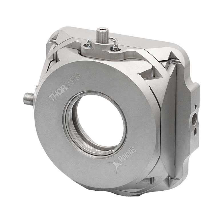 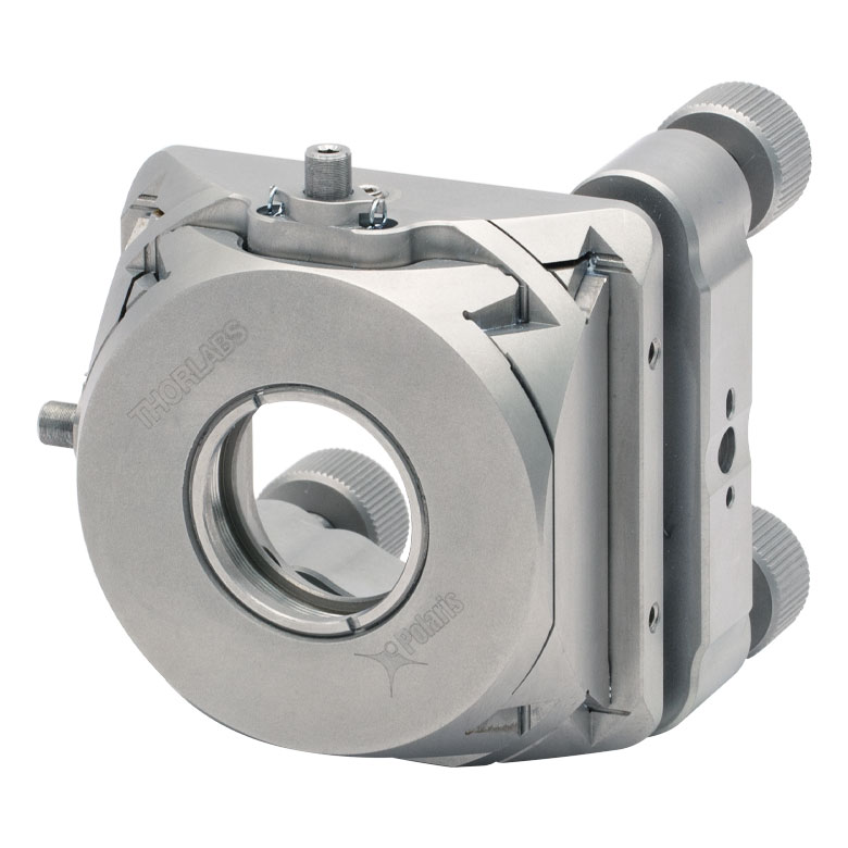 |
|
| 2 Hex Adjusters (X/Y) | -05CXY | |
| -05XY | ||
| 3 Adjuster Knobs (Tip/Tilt/Z) & 2 Hex Adjusters (X/Y) |
-K05XY | |
| Ø1" Optics | ||
| 2 Hex Adjusters (X/Y) | -1XY | |
| 3 Adjuster Knobs (Tip/Tilt/Z) & 2 Hex Adjusters (X/Y) |
-K1XY | |
| Ø1.5" Optics | ||
| 2 Hex Adjusters (X/Y) & 3 Adjuster Knobs (Tip/Tilt/Z) |
-K15XY | |
| Table 103E Polaris Fixed Mounts for Round Optics | ||||||
|---|---|---|---|---|---|---|
| Optic Retention Method | Side Lock | Low Distortion |
Glue-In | Representative Photos |
||
| Ø1/2" Optics | 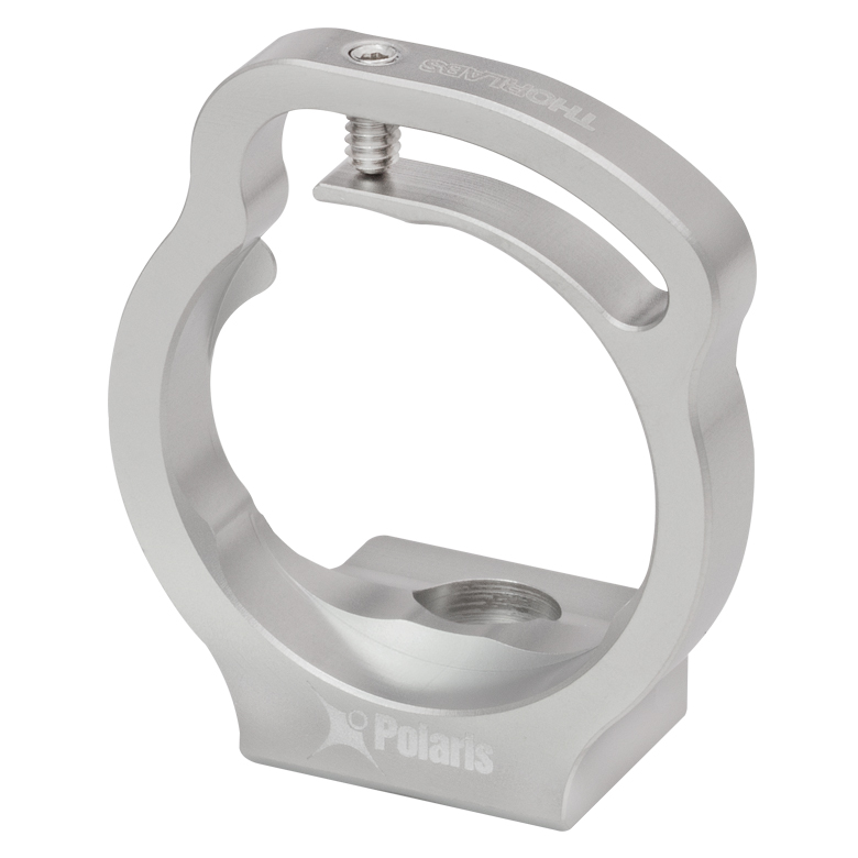 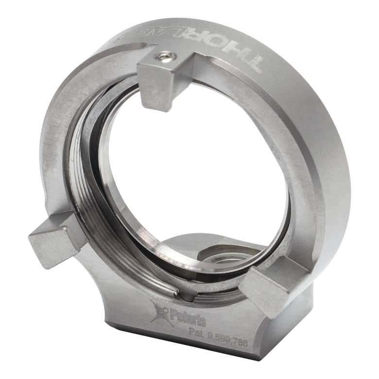 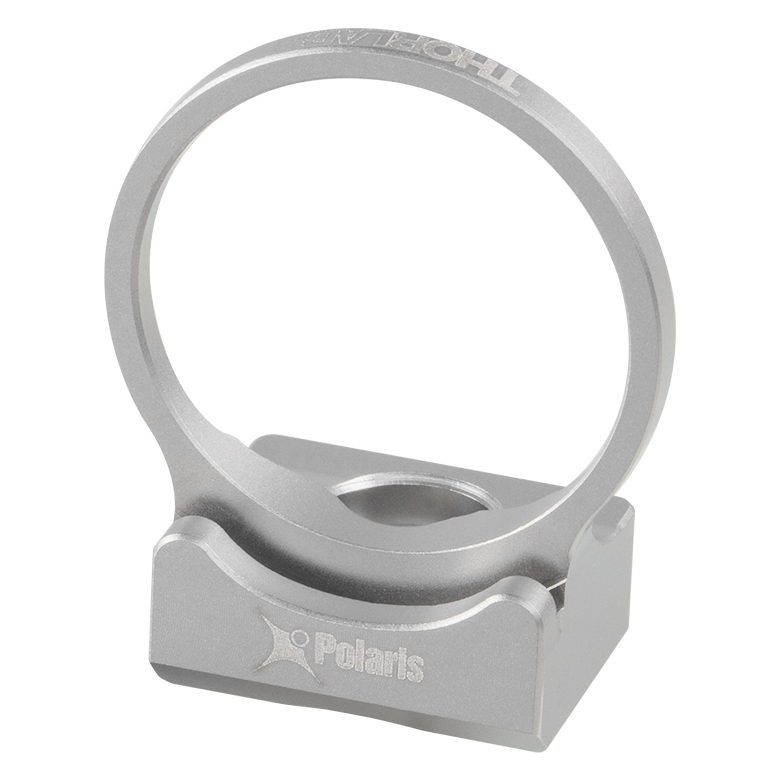 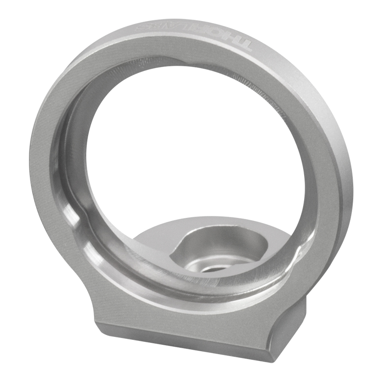 |
|||||
| Optimized for Mirrors | - | -B05F | -C05G | |||
| Optimized for Beamsplitters | -B05S | - | -B05G | |||
| Optimized for Lenses | - | - | -L05G | |||
| Ø19 mm (Ø3/4") Optics | ||||||
| Optimized for Mirrors | -19S50/M | - | - | |||
| Ø1" Optics | ||||||
| Optimized for Mirrors | - | -B1F | -C1G | |||
| Optimized for Beamsplitters | -B1S | - | -B1G | |||
| Optimized for Lenses | - | - | -L1G | |||
| Ø2" Optics | ||||||
| Optimized for Mirrors | - | -B2F | -C2G | |||
| Optimized for Beamsplitters | -B2S | - | - | |||
| Table 103F Polaris Kinematic 1.8" x 1.8" Platform Mount | ||
|---|---|---|
| Optomech Retention Method | Tapped Holes & Counterbores |
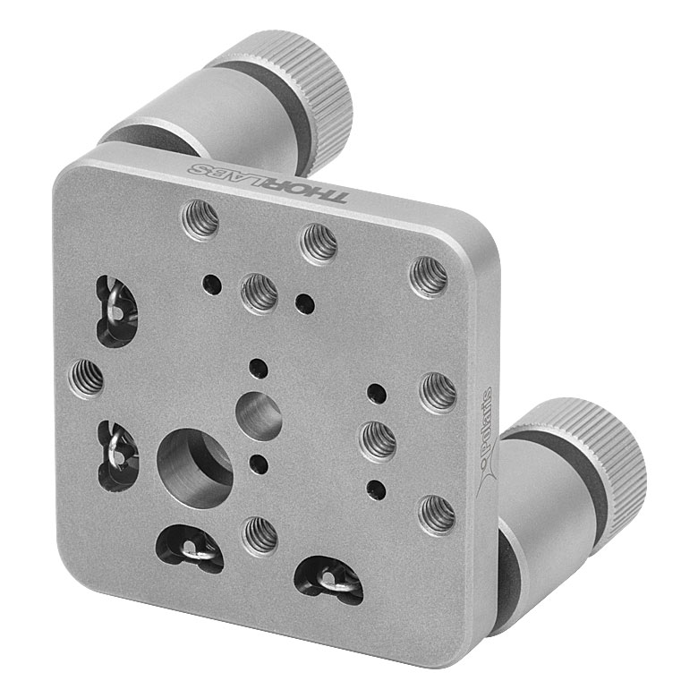 |
| 2 Adjuster Knobs | -K1M4(/M) | |
| Table 103G Accessories for Polaris Mounts | |
|---|---|
| Description | Representative Photos |
| Ø1/2" Posts for Polaris Mounts | 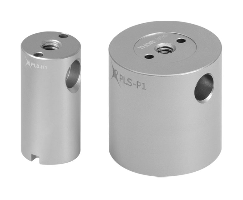 |
| Ø1" Posts for Polaris Mounts | |
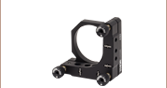
| Non-Bridging Clamping Arms | 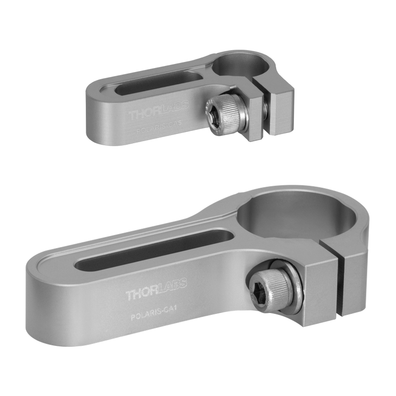 |
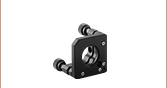
| 45° Mounting Adapter | 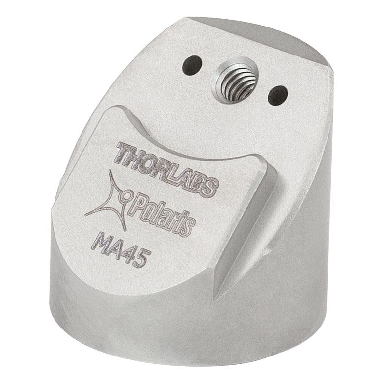 |

 Zoom
Zoom- 2-Adjuster Ultra-Stable Low-Distortion Mount Designed for Ø6" Optics
- Superalloy Aluminum Front Plate Reduces Kinematic Sprung Mass
- Stainless Steel Back Plate Provides Long Term Stability and High Stiffness
- Mounting Features are Included for Heat Pipes and Custom Payload Extensions (See the Design Features Tab)
- Fully Sprung Optic Cell Minimizes Optic Distortion Over Temperatures Ranging -30 to 200 °C
This Ø6" Polaris Low-Distortion Ruggedized Kinematic Mirror Mount is designed to minimize optic distortion and provide long-term stability. This mount is fitted with a three-point-contact faceplate to mount the optic. Three optic retention springs and two side contact pistons secure the optic. See the Optic Installation and Low Distortion tabs for details.
The front plate of the mount is a superalloy aluminum, which reduces the kinematic sprung mass and acts as a heat sink for optics used with ultra-high-power lasers. The reduction in the kinematic sprung mass works to improve beam pointing stability as well as to the minimize the shocks and vibrations absorbed from the operating environment. Additionally, the back plate uses matched actuator-body pairs made from heat-treated stainless steel, which provides long-term stability.
For positioning the optic, the POLARIS-K6F4 mount has two hex adjusters. The 5 mm hex adjuster screws are compatible with our HKM50NM hex key or any other 5 mm hex wrench or ball driver and provide a maximum angular range of ±2°. Each adjuster also features Ø0.096" (Ø2.4 mm) holes that allow actuation from the side. All adjusters are set into polished sapphire seats, ensuring their contact surfaces retain their integrity over a longer period of time than adjusters set in metal seats.
Three 5/16" (M7) counterbored holes at the center and ends of the bottom of the mount can be used to secure the mount in a setup. We recommend matching materials between the back plate and the mounting surface. For example, three PLS-P1 Ø1" stainless steel posts can be used with POLARIS-CA1 clamping arms to secure the POLARIS-K6F4 mount to a breadboard. Note that 1/4"-20 (M6) cap screws with washers will fit into the mount's 5/16" (M7) counterbores, allowing it to be directly connected to Ø1" optical posts. For custom mounting configurations, a single Ø5 mm alignment pin hole is located at each outer counterbore for setting a precise location and mounting angle. Standard 5mm-M6 (ISO 2338) alignment pins are recommended; for details, see the PDF drawing by clicking on the Docs icon ( ) below.
For optimal performance, it can be desirable to apply precise amounts of torque when mounting optics or securing this Polaris mirror mount to a breadboard or posts (see the Usage Tips tab for details). The TD75 torque driver and compatible hex driver bit kits, both of which are sold below, can be used for this application.

 Zoom
Zoom

Click to Enlarge
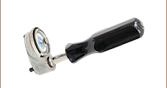
Figure G2.1 The dial face of the TD24 Torque Driver. The black needle indicates the current torque, while the silver memory needle can be used to indicate the desired torque value. The TD75 has a similar dial face.
The TD75 torque driver is equipped with a precision metal combination dial, has a 1/4" square drive socket at the end of the handle, and can provide 0 to 75 lb-in of torque. It is accurate to 2% of the dial reading from 20% of the full scale to the full scale. The design of this torque wrench allows accurate torques to be dialed in regardless of the hand-hold position on the handle.
The precision dial on the driver has two scales. The outer ring of white numbers is the primary scale, and the inner ring of black numbers is the secondary scale. Please see Figure G2.1 for details. The dial also has two needles: a black needle indicates the torque that is being applied to a fixture and a silver memory needle that remains in place after pressure is removed from the handle to mark the peak torque value reached.
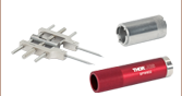
The TD75 torque driver can be used with the two hex driver bit kits offered below. The BDSH-KIT/M metric kit includes all of the bits needed for mounting optics in the POLARIS-K6F4 Ultra-Stable Low-Distortion Ø6" Mirror Mounts. If affixing the mount to posts or custom breadboards using imperial screws, we also recommend the BDSH-KIT Imperial Hex Driver Bit Kit. For additional information on mounting, see the Optic Installation and Usage Tips tabs. Each bit is engraved with its hex size. Table G2.2 lists the hex bits included in each kit. For more information on torque drivers and their accessories, please visit Thorlabs' Torque Drivers webpage.
| Table G2.2 Hex Sizes | |
|---|---|
| Hex Driver Bit Kit Item # | Included Hex Sizes |
| BDSH-KIT | 0.050", 1/16", 5/64", 3/32", 7/64", 1/8", 9/64", 5/32", and 3/16" |
| BDSH-KIT/M | 1.5 mm, 2.0 mm, 2.5 mm, 3.0 mm, 4.0 mm, and 5.0 mm |