 Products Home / Motorized Stages / Motorized Rotation Stages and Mounts / ORIC® Rotation Stages with Piezoelectric Inertia Drive
ORIC® Rotation Stages with Piezoelectric Inertia Drive
- 360° Rotation Stages with Open- or Closed-Loop Positioning
- Piezo Inertia Drive Ideal for Set-and-Hold Applications
- Model with Maximum Speeds up to 100°/s with 30 µrad Typical Step Size When Driven with PDXC Controller
- Backlash-Free Operation
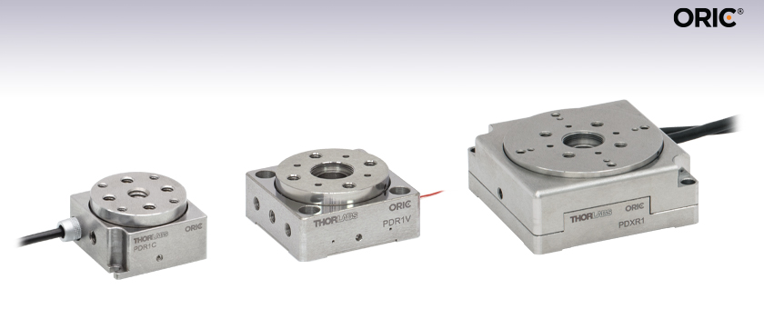
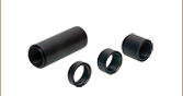
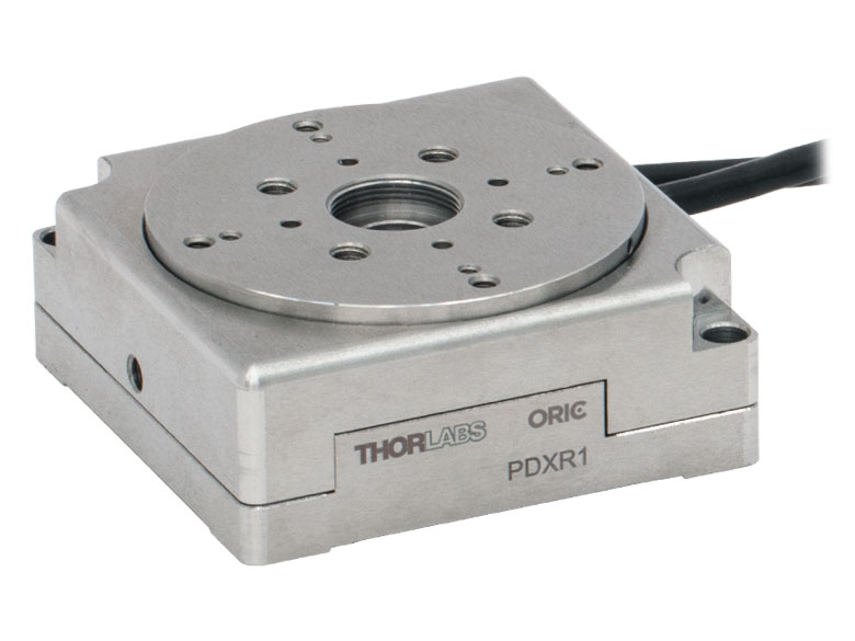
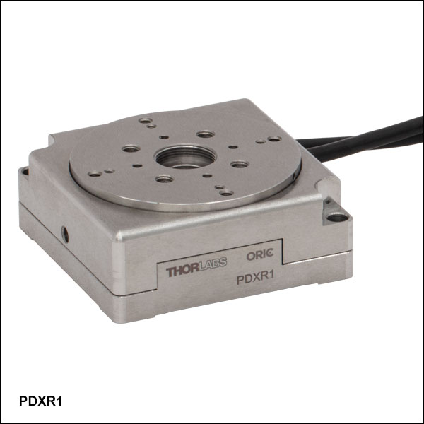
PDXR1
Stage with Optical Encoder,
Ø49.7 mm Platform
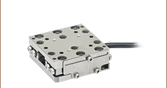
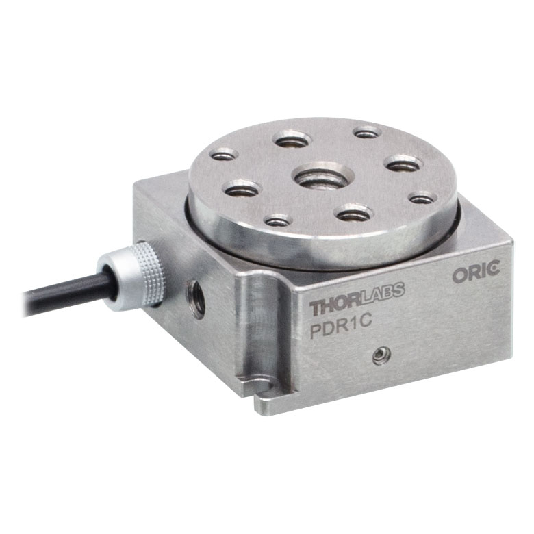
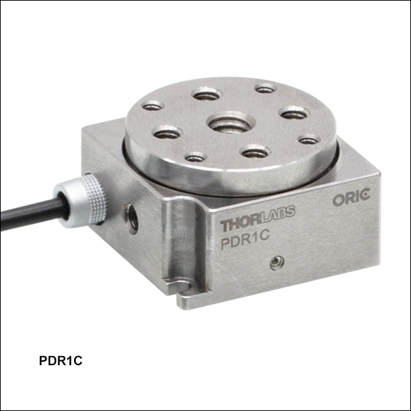
PDR1C
Compact Stage,
Ø28.0 mm Platform
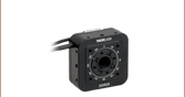
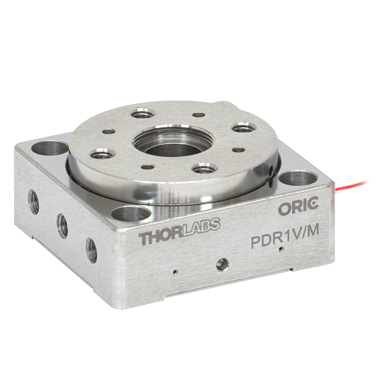
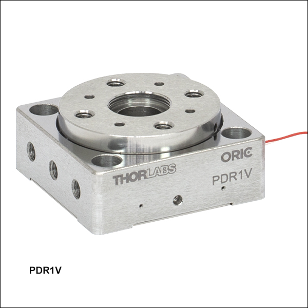
PDR1V
Vacuum-Compatible Stage,
Ø34.0 mm Platform
U.S. Patent 11,606,045


Please Wait
| ORIC® Piezo Inertia Stage Selection Guide |
|---|
| 4.5 mm Vertical Translation Stage |
| 5 mm Linear Translation Stages |
| 12 mm Linear Translation Stages |
| 20 mm Linear Translation Stages |
| 50 mm Linear Translation Stages |
| Rotation Stages |
| Vacuum-Compatible Stages |
| Quick Links | |
|---|---|
| Description | Platform Size |
| Compact Stage | Ø28.0 mm |
| Standard Stage | Ø34.0 mm |
| Vacuum-Compatible Stage | Ø34.0 mm |
| Stage with Optical Encoder | Ø49.7 mm |
| Dowel Pins | |
| Controllers | |
Click to Enlarge
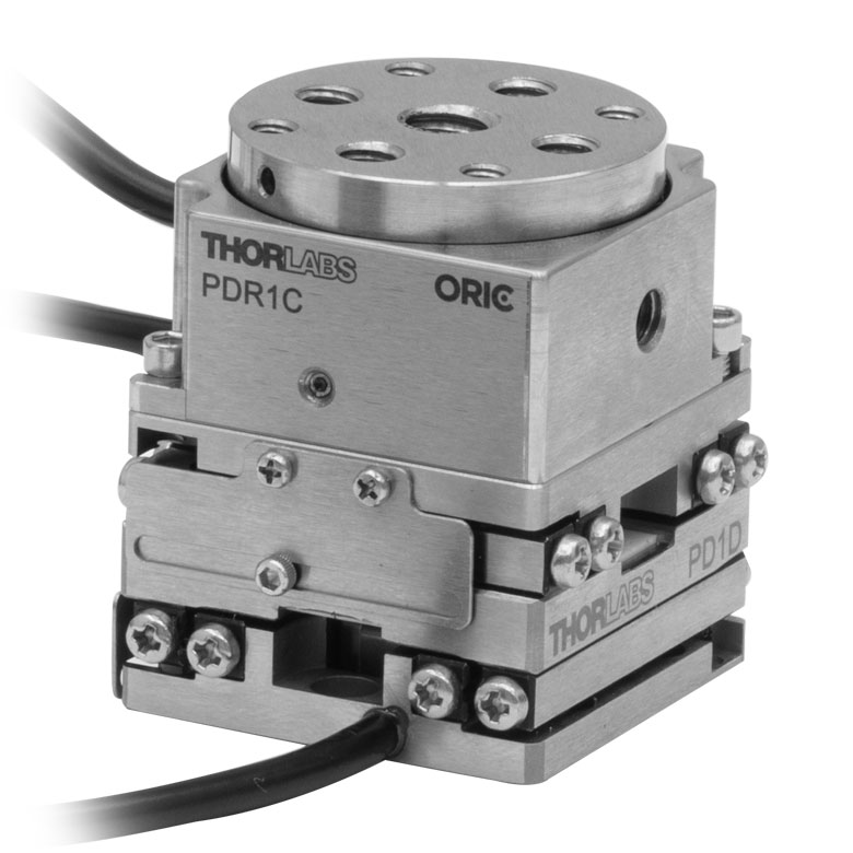
XY + rotation stage created by mounting a PDR1C(/M) rotation stage on a PD1D(/M) XY stage.
Click to Enlarge
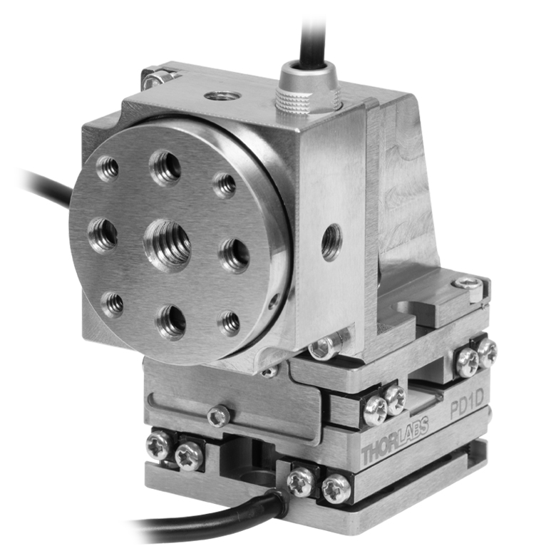
XY + rotation stage created by mounting a PDR1C(/M) rotation stage on a PD1D(/M) XY stage using a PD1Z(/M) right angle bracket.
Features
- Compact Stainless Steel Stages with Piezo Inertia Drive
- Ideal for OEMs and Set-and-Hold Applications that Require Relative Positioning with High Resolution
- Center Bore for Beam Passthrough or Optomech Mounting
- Several Stage Varieties Available (See Table to the Right)
- 8-32 (M4 x 0.7) Hole(s) on Sides for Post Mounting
- Stack with 20 mm or 50 mm Stages to Create XY + Rotation Configurations (See Photos Below)
- Stack with 4.5 mm Vertical Stage to Create Z + Rotation Configurations
- Requires a Piezo Inertia Controller (Sold Separately)
- Vacuum-Compatible Stage Suitable for Pressures Down to 10-6 Torr
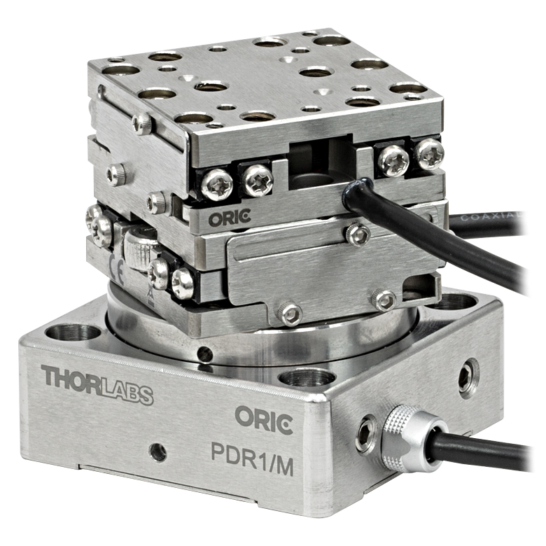
Thorlabs' PDR1 and PDXR1 Series ORIC® Piezoelectric Inertia Drive Rotation Stages (U.S. Patent 11,606,045) provide 360° of stable piezo-controlled rotary motion in compact packages. PDR1 series stages provide open-loop operation in two different sizes, each with different mounting features and performance characteristics, while the PDXR1(/M) stage with an optical encoder supports open- and closed-loop operation. All stages have a horizontal load capacity of 1 kg. The step size is dependent on the load and the drive voltage and can be further adjusted by changing the rise and fall voltages used to control the stages. For details, refer to the Specs tab above. In addition to continuous long-term stepping, the stages can also be used in a rotate-and-hold mode. The PDR1V(/M) stage is a vacuum-compatible version of the PDR1(/M) stage with flying leads.

Compatibility with Other ORIC Stages
These rotation stages can be combined with ORIC 20 mm or 50 mm travel linear stages to create an XY + rotation stage. See the photos to the right for examples using a PD1D(/M) monolithic 20 mm XY stage and the PDR1C(/M) rotation stage. The rotation stages can also be mounted on a PDXZ1(/M) vertical translation stage to create a Z + rotation stage.
A PD1U(/M) adapter plate is required to mount a PDR1(/M) or PDR1V(/M) stage on a PD1(/M) linear stage or PD1D(/M) XY stage. A PDR1(/M) or PDR1V(/M) rotation stage can also be mounted on top of a PD3(/M) or PDX3(/M) 50 mm linear stage using ER05-P4 cage rods and the PD3T(/M) adapter plate.
Click to Enlarge
Simplified Illustration Showing the Operation of the Piezo Inertia Drive
The "stick-slip" cycle consists of a slow piezo expansion and a fast piezo contraction.
Piezoelectric Inertia "Stick-Slip" Motor
The piezo inertia motor consists of three main parts: a flexure-coupled piezo actuator, a friction element, and a rotating platform. For clockwise rotation, the piezo slowly expands under the ramp voltage during the "stick" part of the cycle, pushing the friction element and the rotating platform in unison. During the "slip" part, the drive voltage drops rapidly, and the piezo element returns to its starting length, with the friction element "slipping." Due to the rotating platform's inertia and the low coefficient of kinetic friction between the friction element and the surface of the platform, the rotating platform does not reverse its direction during this process. The graph to the right shows the piezo drive voltage during one "stick-slip" cycle.
Repeating this cycle produces continuous clockwise rotation of the stage. For rotation in the reverse direction, the opposite drive voltage pattern is required, resulting in rapid piezo expansion and slower piezo contraction, or "slip-stick."
The achieved step size will vary and is not repeatable due to several factors, including the application conditions, piezo hysteresis, component variance, and the axial load. To help overcome this variance, an external feedback system will be necessary.
| Item # | PDR1C(/M)a | |
|---|---|---|
| Driving Controller | PDXC or PDXC2 Benchtop Controller |
KIM001 or KIM101 K-Cube® Controllers |
| Rotation Range | 360° Continuous | |
| Step Size | 30 µrad (Typical)b; <60 µrad (Max)c |
150 µrad (Typical)b; <200 µrad (Max)c |
| Step Size Adjustabilityc | Up to 100% | None |
| Maximum Step Frequencyd | 20 kHz | 2 kHz |
| Maximum Speed (Continuous Stepping)e,f |
100°/s (Typical) | 30°/s (Typical) |
| Speed Variation Over Travel Range (Average)f |
±10% (Typical) | |
| Horizontal Load Capacity | 1 kg (2.2 lbs) | |
| Vertical Load Torque Capacityg | 10 mN•m | 15 mN•m |
| Holding Torque | 20 mN•m | |
| Wobble | ≤200 µrad | |
| Lifetimeh | >10 Billion Steps | |
| Connector Type | Female SMC | |
| Cable Length | 1 m (3.3 ft)i | |
| Piezo Capacitance | 170 nF | |
| Operating Voltage | 125 V (Max) | |
| Operating Temperature | 10 to 40 °C (50 to 104 °F) | |
| Dimensions | 30.0 mm x 30.0 mm x 18.0 mm (1.18" x 1.18" x 0.71") |
|
| Weight (Including Cable) | 96 g (3.39 oz) | |
| Required Controllerj (Sold Separately Below) |
PDXC, PDXC2k, KIM001, or KIM101 | |
| Item # | PDR1(/M) | PDR1V(/M) |
|---|---|---|
| Driving Controller | KIM001 or KIM101 K-Cube® Controllersa | |
| Rotation Range | 360° Continuous | |
| Step Size | 250 µrad (Typical)b; <350 µrad (Max)c |
|
| Step Size Adjustabilityc | Up to 30% | |
| Maximum Step Frequency | 2 kHz | |
| Maximum Speed (Continuous Stepping)d | 20°/s (Typical) | |
| Speed Variation Over Travel Range (Average)d | ±10% (Typical) | |
| Horizontal Load Capacity | 1 kg (2.2 lbs) | |
| Vertical Load Torque Capacitye | 15 mN•m | |
| Holding Torque | 25 mN•m | |
| Wobble | ≤200 µrad | |
| Lifetimef | >10 Billion Steps | >10 Billion Stepsg |
| Vacuum Compatibility | N/A | 10-6 Torr |
| Connector Type | Female SMC | Flying Leads Attached to Stage; Additional Bare Lead-to-SMC Female Cable Included |
| Cable Length | 1 m (3.3 ft)h | 0.75 m (2.46 ft) Flying Lead for Vacuum; 1.0 m (3.3 ft)i Cored Cable for Wiring Outside Chamber |
| Piezo Capacitance | 170 nF | |
| Operating Voltage | 125 V (Max) | |
| Operating Temperature | 10 to 40 °C (50 to 104 °F) | |
| Dimensions | 40.0 mm x 40.0 mm x 18.0 mm (1.57" x 1.57" x 0.71") |
|
| Weight (Including Cable) | 151 g (5.33 oz) | 163 g (5.75 oz) |
| Required Controller (Sold Separately Below) |
KIM001 or KIM101 | |
| Item # | PDXR1(/M)a |
|---|---|
| Driving Controller | PDXC Benchtop Controller |
| Rotation Range | 360° Continuous |
| Optical Encoder Resolution | 0.4365 µrad (0.09 arcsec) |
| Minimum Incremental Motionb | 0.873 µrad (0.18 arcsec) |
| Step Size | 0.01 to 999.0° Using PDXC Only 0.00005 to 180.0° Using Software |
| Step Frequency | 20 kHz |
| Speed Adjustment Range (Continuous Stepping)b,c |
10 to 30°/s (Typical) |
| Speed Variation Over Travel Range (Average)b |
±3% (Typical) |
| Horizontal Load Capacity | 1 kg (2.2 lbs) |
| Vertical Load Torque Capacityc | 15 mN•m |
| Holding Torque | 25 mN•m |
| Wobble | ≤200 µrad |
| Lifetimee | ≥210 000 Revolutions |
| Connector Type | 15-Pin D-Sub Female |
| Cable Lengthf | 1.5 m (4.9 ft), PDXCE Cable (Optional, Not Included): 3 m (9.8 ft) |
| Piezo Capacitance | 65 nF |
| Operating Voltage | 60 V (Max) |
| Operating Temperature | 10 to 40 °C (50 to 104 °F) |
| Dimensions | 56.0 mm x 56.0 mm x 23.0 mm (2.20" x 2.20" x 0.91") |
| Mass (Including Cable) | 380 g (13.4 oz) |
| Required Controller (Sold Separately Below) |
PDXCg or PDXC2 |
PDR1C(/M) & PDR1(/M)
Female SMC

0 to 125 V
PDR1V(/M)
Flying Leads
0 to 125 V
PTFE Jacket, 30 AWG
Additional Cable with
Female SMC Connector*
0 to 125 V
*The PD1V(/M) includes an additional bare lead-to-SMC cable.
PDX1(/M)
Female 15-Pin D-Sub
| Pin(s) | Voltage Range | Name | Description |
|---|---|---|---|
| 1 | -7.5 to +12.5 V | Encoder_B_N | Encoder B- |
| 2 | -7.5 to +12.5 V | Encoder_B_P | Encoder B+ |
| 3 | 0 V | GND | Digital Ground |
| 4 | -7.5 to +12.5 V | Encoder_A_N | Encoder A- |
| 5 | -7.5 to +12.5 V | Encoder_A_P | Encoder A+ |
| 6 | - | - | Reserved |
| 7 | - | - | Reserved |
| 8 | +5 V | +5 V | 5 V Power |
| 9 | -7.5 to +12.5 V | Encoder_Z_N | Encoder Z- |
| 10 | -7.5 to +12.5 V | Encoder_Z_P | Encoder Z+ |
| 11 | -10 to +50 V | SigOut2 | Piezo Output 2 |
| 12 | 0 V | PGND | Power Ground |
| 13 | -10 to +50 V | SigOut1 | Piezo Output 1 |
| 14 | 5 V TTL | EEPROM | 1-Wire EEPROM |
| 15 | - | - | Reserved |
Software
PDXC Version 2.2.1
The PDXC Software Package, which includes a GUI, drivers, and LabVIEW™/C++/Python SDK for third-party development.
Thorlabs offers the PDXC software package to interface with the PDXC Piezo Stage Controller. This controller is designed to drive the following piezo inertia stages:
- PDXZ1(/M) 4.5 mm Vertical Stage with Optical Encoder
- PD2(/M) 5 mm Linear Stage
- PDX2(/M) 5 mm Linear Stage with Optical Encoder
- PDX4(/M) 12 mm Linear Stage with Optical Encoder
- PD1(/M) 20 mm Linear Stage
- PD1V(/M) Vacuum-Compatible 20 mm Linear Stage
- PD1D(/M) 20 mm Monolithic XY Stage
- PDX1(/M) 20 mm Linear Stage with Optical Encoder
- PDX1A(/M) 20 mm Low-Profile, Linear Stage with Optical Encoder
- PDX1AV(/M) Vacuum-Compatible 20 mm Low-Profile, Linear Stage with Optical Encoder
- PD3(/M) 50 mm Linear Stage
- PDX3(/M) 50 mm Linear Stage with Optical Encoder
- PDR1C(/M) Rotation Stage
- PDXR1(/M) Rotation Stage with Optical Encoder
The software package allows two methods of usage: graphical user interface (GUI) utilities for direct interaction with and control of the controllers 'out of the box', and a set of programming interfaces for third-party development of custom-integrated positioning and alignment solutions to be easily programmed in the development language of choice (LabVIEW™/C++/Python SDK).
Software
Kinesis Version 1.14.53
The Kinesis Software Package, which includes a GUI for control of Thorlabs' Kinesis system controllers.
Also Available:
- Communications Protocol
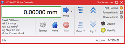
Figure 58A Kinesis GUI Screen
Thorlabs offers the Kinesis® software package to drive our wide range of motion controllers. The software can be used to control devices in the Kinesis family, which covers a wide variety of motion controllers ranging from small, low-powered, single-channel drivers (such as the K-Cubes®) to high-power, multi-channel benchtop units and modular 19" rack nanopositioning systems (the MMR60x Rack System).
The Kinesis Software features .NET controls which can be used by 3rd party developers working in the latest C#, Visual Basic, LabVIEW™, or any .NET compatible languages to create custom applications. Low-level DLL libraries are included for applications not expected to use the .NET framework and APIs are included with each install. A Central Sequence Manager supports integration and synchronization of all Thorlabs motion control hardware.
By providing this common software platform, Thorlabs has ensured that users can mix and match any of our motion control devices in a single application, while only having to learn a single set of software tools. In this way, it is perfectly feasible to combine any of the controllers from single-axis to multi-axis systems and control all from a single, PC-based unified software interface.
The software package allows two methods of usage: graphical user interface (GUI) utilities for direct interaction with and control of the controllers 'out of the box', and a set of programming interfaces that allow custom-integrated positioning and alignment solutions to be easily programmed in the development language of choice.
Thorlabs' Kinesis® software features new .NET controls which can be used by third-party developers working in the latest C#, Visual Basic, LabVIEW™, or any .NET compatible languages to create custom applications.
C#
This programming language is designed to allow multiple programming paradigms, or languages, to be used, thus allowing for complex problems to be solved in an easy or efficient manner. It encompasses typing, imperative, declarative, functional, generic, object-oriented, and component-oriented programming. By providing functionality with this common software platform, Thorlabs has ensured that users can easily mix and match any of the Kinesis controllers in a single application, while only having to learn a single set of software tools. In this way, it is perfectly feasible to combine any of the controllers from the low-powered, single-axis to the high-powered, multi-axis systems and control all from a single, PC-based unified software interface.
The Kinesis System Software allows two methods of usage: graphical user interface (GUI) utilities for direct interaction and control of the controllers 'out of the box', and a set of programming interfaces that allow custom-integrated positioning and alignment solutions to be easily programmed in the development language of choice.
For a collection of example projects that can be compiled and run to demonstrate the different ways in which developers can build on the Kinesis motion control libraries, click on the links below. Please note that a separate integrated development environment (IDE) (e.g., Microsoft Visual Studio) will be required to execute the Quick Start examples. The C# example projects can be executed using the included .NET controls in the Kinesis software package (see the Kinesis Software tab for details).
 |
Click Here for the Kinesis with C# Quick Start Guide Click Here for C# Example Projects Click Here for Quick Start Device Control Examples |
|
LabVIEW
LabVIEW can be used to communicate with any Kinesis-based controller via .NET controls. In LabVIEW, you build a user interface, known as a front panel, with a set of tools and objects and then add code using graphical representations of functions to control the front panel objects. The LabVIEW tutorial, provided below, provides some information on using the .NET controls to create control GUIs for Kinesis-driven devices within LabVIEW. It includes an overview with basic information about using controllers in LabVIEW and explains the setup procedure that needs to be completed before using a LabVIEW GUI to operate a device.
 |
Click Here to View the LabVIEW Guide Click Here to View the Kinesis with LabVIEW Overview Page |
|
Achieving the Specified Performance
In this application note, we will discuss how to achieve the specified velocity and step size for the open-loop PD1(/M), PD1D(/M), and PDR1(/M) ORIC® Stages when driving them with KIM001 or KIM101 K-Cube® Controllers; examples using the Kinesis® software and the K-Cube's front panel controls are discussed below. There are limitations when using an open-loop system, and we have created this application note to help minimize velocity and step size variation. We recommend using this application note upon initial setup, and/or if you are having issues with velocity and step size variation. For further details on how to change settings, please refer to the manuals of the individual stage and controller.
Click to Enlarge
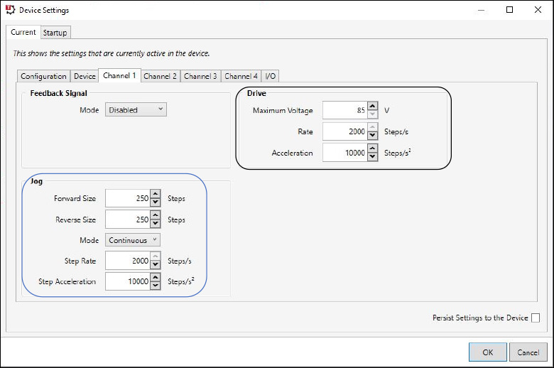
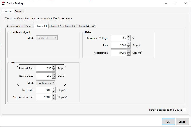
Figure 95B These are the recommended channel settings for the PD(R) stage type. They can be changed in Device Settings -> Current Device Settings-> Channel 1.
Click to Enlarge
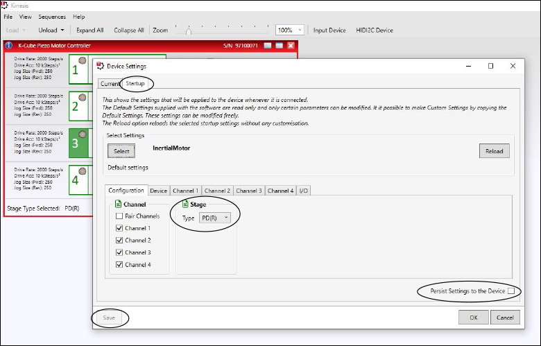
Figure 95A When controlling an ORIC Stage, the stage type needs to be set to PD(R). This can be found in the Kinesis Software Device Settings -> Startup.
Click to Enlarge
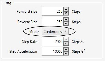
Figure 95D Depicted in the circle is the jog mode, which should be set to continuous. This can be changed in Device Settings -> Current ->

Figure 95C Circled in black are the jog buttons which can be found in the device GUI.
Kinesis© Software Control with a K-Cube Controller
The Kinesis software defaults the stage type to PIA, which is not applicable to ORIC stages; to change this, we need to change the startup settings. The startup settings can be found by first accessing the device settings in the device GUI panel and then clicking the Startup tab. Under the Configuration tab, change the stage type to PD(R), check the "Persist Settings to the Device" box on the bottom right, and click the "Save" button in the lower left corner. These selections are shown circled in Figure 95A. By using these settings, the Kinesis software will use the PD(R) stage type. The other device and channel settings can also be changed in the startup settings.
With the PD(R) stage type, we recommend certain channel settings to achieve the specified speed, speed variation, and force. These settings can be changed in the "Channel 1" tab of the device settings and are depicted in Figure 95B. We will be focusing on the settings in the “Drive” box, circled in black, and the "Jog" box, circled in blue.
For the "Drive" box, we recommend setting the "Maximum Voltage" to 85 V, the "Rate" at 2000 steps/s, and "Acceleration" to 10000 Steps/s2. For the settings in the "Jog" box, we recommend setting the "Forward Size" to 250 Steps, the "Reverse Size" to 250 Steps, the "Mode" to "Continuous", the "Step Rate" to 2000 Steps/s, and the "Step Acceleration" to 10000 Steps/s2. To achieve the specified results, it is important to make sure the stage is mounted properly to an even surface, to our recommended mounting plate, or to a compatible adapter plate.
A continuous jog at a step rate higher than 1000 steps/s can only be achieved by using the jog buttons in the device GUI, shown circled in Figure 95C. Continuous jog movement is limited to within 1000 step/s when using the joystick on the KIM101 K-Cube Controller or wheel on the KIM001 K-Cube Controller. Single movement or movement by counts is not limited to 1000 step/s when using the joystick or wheel.
Please note that if you change the jog mode in Kinesis to "Continuous" or "Single" this will only influence the jog buttons in the Kinesis GUI, shown circled in Figure 95C. This will not change the joystick mode on the KIM001 or KIM101 controller front panel. The jog mode can be found in Kinesis under Device settings -> Channel 1 -> "Jog" box -> "Mode", also shown in Figure 95D. More information on this can be found in the Front Panel Control section, located below.
Click to Enlarge
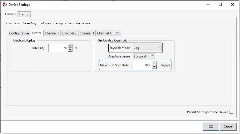
Figure 95F Kinesis software showing the "Device" tab under Device Settings in the Device GUI. The "Maximum Step Rate" setting is circled in blue. To use the joystick with continuous jogging mode this setting must be less than 1000 steps/s. The Kinesis joystick modes can be selected via the dropdown menu circled in black.
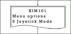
Figure 95E Drawing of the front panel of the KIM101 K-Cube Controller showing option 5, Joystick Mode.
Click to Enlarge
Figure 95H Kinesis software showing where the step size can be changed using the "Forward Size" and "Reverse Size" settings. The "Mode" setting, also shown, only affects the controls of the jog buttons in the GUI and does not affect the joystick mode.
Click to Enlarge
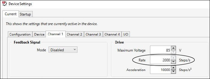
Figure 95G The drive rate can be changed in the Kinesis software under Device Settings -> Current -> Channel 1. This is equivalent to Front Panel Control option 3, "Set Velocity".
KIMx01 Front Panel Control and Related Settings in Kinesis
There are 10 options on the front panel control menu. These can be accessed using the two buttons and joystick on the KIM101 K-Cube Controller or the button and wheel on the KIM001 K-Cube Controller.
Option 5, Joystick Mode, shown in Figure 95E, has 3 modes: "Jog to Count", "Jogging in Steps", and "Velocity Control". The Joystick mode in the Kinesis software is related to option 5, Joystick Mode, on the front panel. The three options for the Joystick Mode in the Kinesis software are "Step Rate", "Jog", and "Goto Position". This setting is circled in black in Figure 95F.
"Jog to Count" mode will move the stage to the target count, which is defaulted at 0, under the velocity that is set by option 3, "Set Velocity" on the front panel. The setting for option 3 is the velocity at which the stage will move for option 5’s “Jog to Count” mode and for option 1, "Goto Pos Count". There is an equivalent setting in Kinesis which can be found in Device Settings -> Channel 1 -> "Drive" box -> "Rate". This is shown in Figure 95G.
In "Jogging in Steps" mode, option 3, "Set Velocity" does not change the stage's velocity. The velocity in this mode must be changed in the Kinesis software. This can be changed in Device settings -> Channel 1 -> "Jog" box -> "Step Rate". Instead of changing the step rate to increase the stage speed, the step size can be changed to increase the stage speed. The step size can be changed on the front panel of a KIM001 or KIM101 device through option 4, "Jog Step Size". This can also be achieved in Kinesis through Device settings -> "Channel 1" -> "Jog" box-> "Forward Size" and "Reverse Size", shown in Figure 95H.
In option 5 "Velocity Control" mode, the joystick can be used to achieve continuous jogging, but only if the velocity is less than 1000 step/s. This velocity cannot be changed by option 3 on the front panel. The velocity can only be changed in the Kinesis software under the Device settings -> Device -> "Maximum Step Rate", shown in Figure 6. A value of 10000 may appear initially, but this value is not accepted by the software and must be revised to a number between 1 and 1000.
In Kinesis, the joystick mode "Step Rate", is related to the "Velocity Control" mode on the front panel and can use the setting of "Maximum Step Rate". The "Direction Sense" can be used to switch the travel direction when using the joystick or wheel.
| Posted Comments: | |
Christian Winter
(posted 2025-05-15 12:52:43.923) There is a center of rotation for this stage, and there is a fixing screw pattern and outside dimensions. What I cannot find is a value for the spatial relation for these patterns.
Could you provide a drawing that allows a reasonable positioning of the product? jdelia
(posted 2025-05-21 07:58:18.0) Thank you for contacting Thorlabs. There is a 1mm offset between the center of the rotation and the two fixing screw patterns. We will reach out to you directly via email to provide the dimension information. Caijin Xie
(posted 2025-05-06 08:55:00.317) This is our previous feedback in English.
We are researchers from Sun Yat-sen University. Previously, we purchased the PDR1/M device from your Thorlabs website for our experimental platform setup. However, due to space constraints, we are unable to use the accompanying controller and need to control the device using our FPGA based electronics.
We would like to inquire if you could provide the communication protocol and internal encoding scheme of the PDR1/M to facilitate our follow-up experiments. Your support would be greatly appreciated.
Thank you for your assistance!
Best regards,
Caijin Xie
Sun Yat-sen University cdolbashian
(posted 2025-05-09 11:31:51.0) Thank you for your inquiry. Our local tech support team in PRC has reached out to you directly to discuss your inquiries further. Caijin Xie
(posted 2025-05-06 02:06:11.83) 您好,我们是中山大学的相关科研人员,之前在索雷博官网上购买了PDR1/M,想用于我们的实验平台搭建,受限于空间问题,我们无法采用配套的控制器进行控制,需要使用我们手上已有的FPGA进行控制。想咨询一下能否提供PDR1/M的通信协议以及内部的编码方式,方便我们进行后续的实验,感谢。 Bohdan Bilash
(posted 2025-01-03 14:32:33.177) Hello! I have a question about PDR1.
Can we use it as DC Servo Motor? We want to rotate waveplates with specific angles. How can we adjust those angles using the piezo stage?
Thank you! cdolbashian
(posted 2025-01-10 01:16:01.0) Thank you for contacting Thorlabs. The PDR1 has an open-loop piezo inertia drive that pushes the rotating platform in steps of one ‘stick-slip’ cycle. You can set the number of steps per motion in software or on the controller panel; a typical step size for the PDR1 is 250 µrad. Please note that the achieved step size will vary and is not repeatable due to several factors, including the application conditions, piezo hysteresis, component variance, and the axial load. Under the "Open-Loop Stage Setup" tab, there is some settings information to help minimize velocity and step size variation. But if high repeatability and accuracy like DC Servo Motor is required, an external feedback system will be necessary. In such cases, we recommend the PDXR1, which is equipped with an optical encoder to support closed-loop operation. JHAO YING GUO
(posted 2024-06-18 16:32:47.677) I have a small question about this rotation stage. Can it move back and forth quickly? We need a stage that can rapidly oscillate with a frequency of about 1 kHz and a rotation angle of about 1 degree. Can this stage meet these requirements, or do you have other products you can recommend? Please feel free to contact me. Thank you. cdolbashian
(posted 2024-07-01 01:37:59.0) Thank you for your query. The maximum speed (continuous stepping) of PDR1C(/M) controlled by PDXC or PDXC2 is only 100°/s (typical). I have reached out to you directly to discuss your application. Yulong Dong
(posted 2024-02-02 10:49:26.207) Hi, I'm wondering, in the stick-slip motion of the piezo stage, what is the approximate timescale of the "stick" part and "slip" part in each step, respectively? During the "slip" part, would the stage stay still, or would it wobble or rotate back a little? cdolbashian
(posted 2024-02-16 09:37:59.0) Thank you for contacting Thorlabs. Unbalanced driving generates slow "stick" and fast "slip". The step time is dependent on the stage type, load and the drive voltage, and the fastest step time can be referred to the "Maximum Step Frequency" as shown in the "Specs" tab. In maximum step frequency of 20kHz, the timescale is in micro seconds. During the "slip" part, the piezo contracts quickly and the kinetic friction pulls the stage back a little. We have contacted you directly to discuss this. Oriol A.
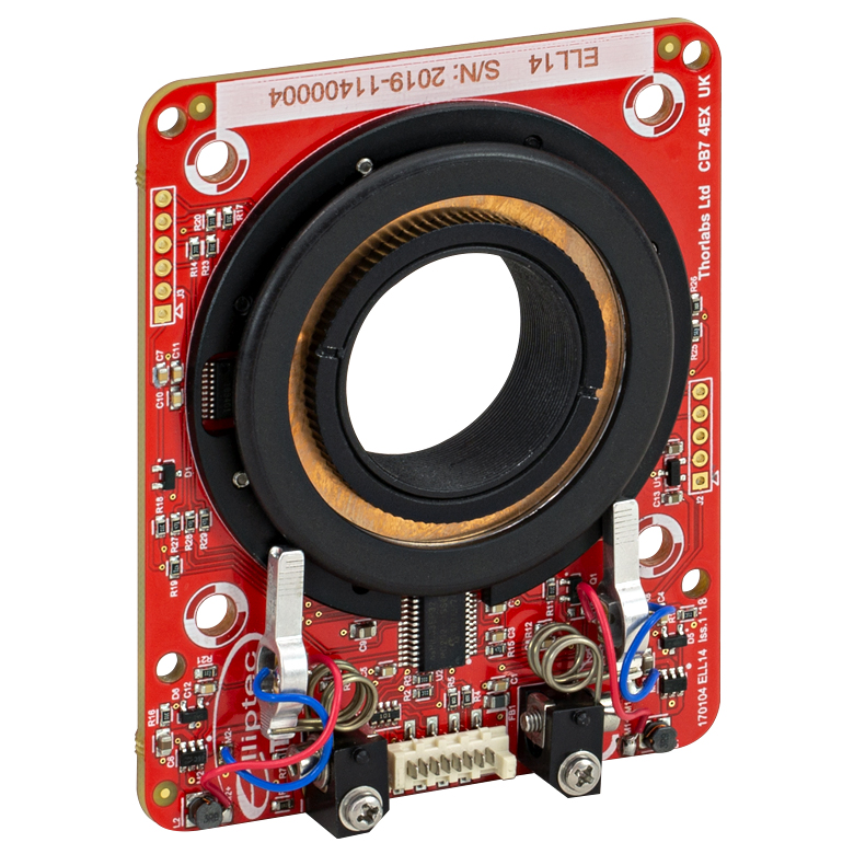
(posted 2021-06-18 04:50:39.913) How well do they compare with the elliptec motors, in particular the ELL14? For discrete positioning of optical elements the ELL14 is sometimes not accurate enough, does this one have better resolution and repeatability? cdolbashian
(posted 2021-06-25 11:25:33.0) Thank you for contacting us at Thorlabs! What of resolution and repeatability are you looking for? What kind of limitations have you experienced with your ELL14? I have reached out to you with some more questions, and look forward to finding a suitable solution for your application! Xiao Wang
(posted 2021-04-21 20:00:45.52) Hi, the product page says that the piezo inertia drive is self-locking when the stage is at rest and no power is supplied to the piezo, but I find I can still rotate it manually without power supply. Is that normal??? YLohia
(posted 2021-04-22 10:58:36.0) Thank you for contacting Thorlabs. The PD1R stage has a holding torque of 25 mN•m. Considering its 34mm rotation plate diameter, a 0.73 N force tangent to the rim would move the plate. The holding torque is intended for locking the stage to make it impervious to vibrations from the setup or environment. Mark Saffman
(posted 2020-07-18 16:37:55.52) A question about the PDR1. The product page says the stages emit a high pitched noise and generate heat when they rotate. DO the stages cause vibration when rotating? I am concerned about vibrations affecting laser locks. YLohia
(posted 2020-07-21 10:21:56.0) Thank you for contacting Thorlabs. PDR1 utilizes a piezoelectric inertia drive that is driven by signals of frequencies up to 2 kHz. These frequencies are audible to humans as high pitch noise. The influence of this 2 kHz vibration is much smaller than the overall wobble of the device. |
Rotation Mount and Stage Selection Guide
Thorlabs offers a wide variety of manual and motorized rotation mounts and stages. Rotation mounts are designed with an inner bore to mount a Ø1/2", Ø1", or Ø2" optic, while rotation stages are designed with mounting taps to attach a variety of components or systems. Motorized options are powered by a DC Servo motor, 2 phase stepper motor, piezo inertia motor, or an Elliptec™ resonant piezo motor. Each offers 360° of continuous rotation.
Manual Rotation Mounts
| Rotation Mounts for Ø1/2" Optics | |||||||
|---|---|---|---|---|---|---|---|
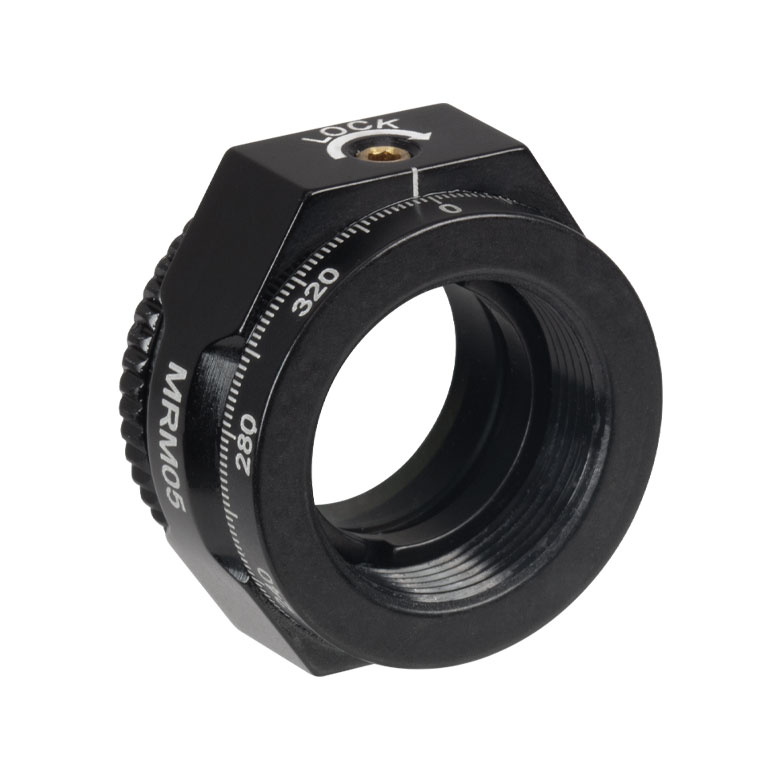
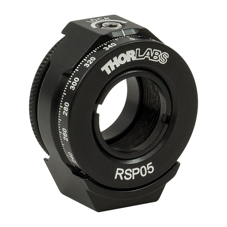
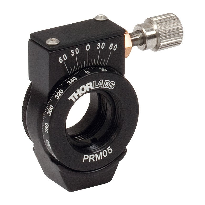
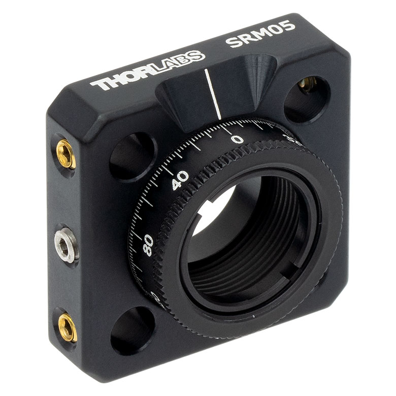
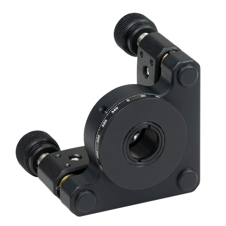
| Item # | MRM05(/M) | RSP05(/M) | CRM05 | PRM05(/M)a | SRM05 | KS05RS | CT104 |
| Click Photo to Enlarge |
 |
 |
 |
 |
 |
 |
 |
| Features | Mini Series | Standard | External SM1 (1.035"-40) Threads |
Micrometer | 16 mm Cage-Compatible | ±4° Kinematic Tip/Tilt Adjustment Plus Rotation | Compatible with 30 mm Cage Translation Stages and 1/4" Translation Stagesb |
| Additional Details | |||||||
| Rotation Mounts for Ø1" Optics | ||||||||
|---|---|---|---|---|---|---|---|---|
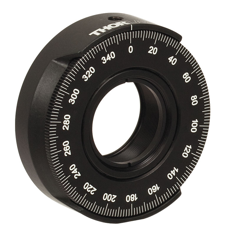
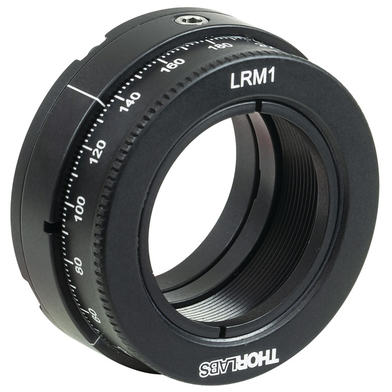
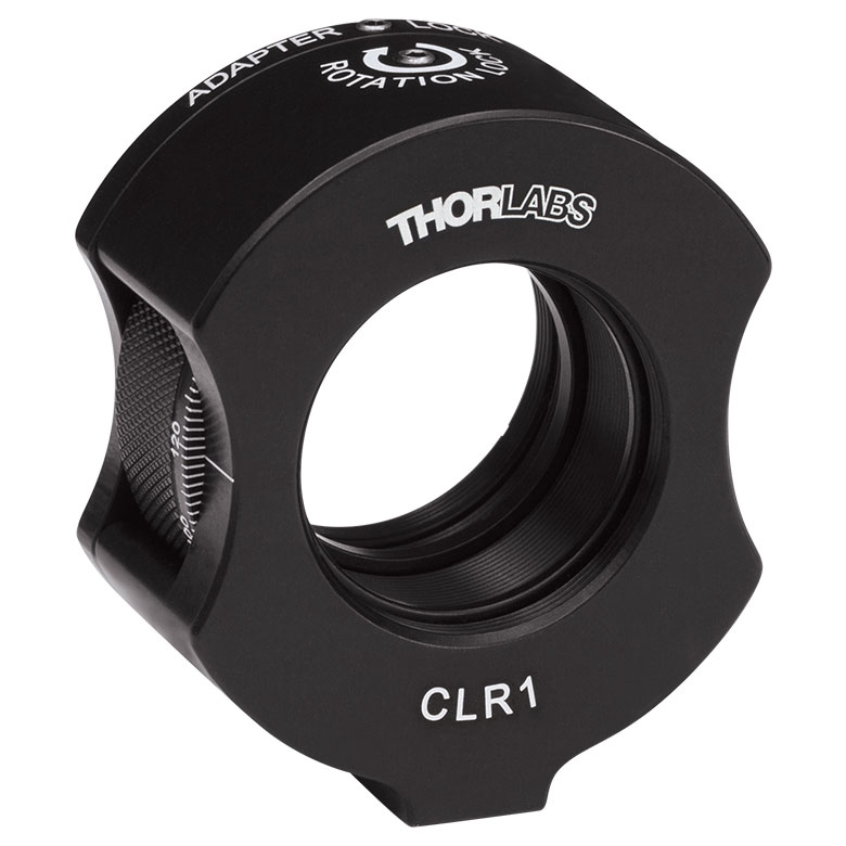
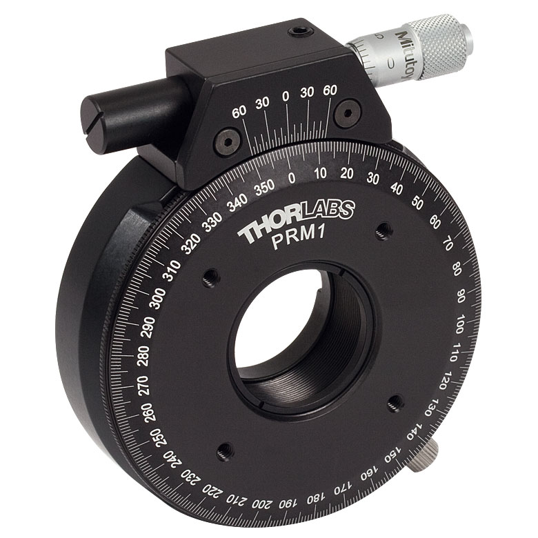
| Item # | RSP1(/M) | LRM1 | RSP1D(/M) | DLM1(/M) | CLR1(/M) | RSP1X15(/M) | RSP1X225(/M) | PRM1(/M)a |
| Click Photo to Enlarge |
 |
 |
 |
 |
 |
 |
|
 |
| Features | Standard | External SM1 (1.035"-40) Threads |
Adjustable Zero | Two Independently Rotating Carriages | Rotates Optic Within Fixed Lens Tube System |
Continuous 360° Rotation or 15° Increments |
Continuous 360° Rotation or 22.5° Increments |
Micrometer |
| Additional Details | ||||||||
| Rotation Mounts for Ø1" Optics | ||||||
|---|---|---|---|---|---|---|
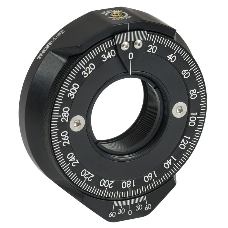
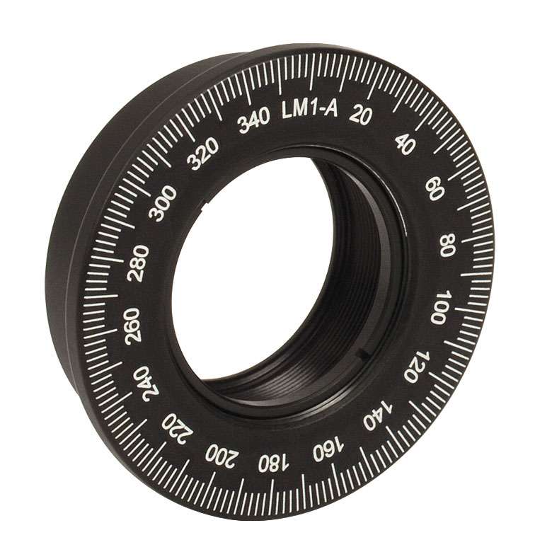
| Item # | LM1-A & LM1-B(/M) |
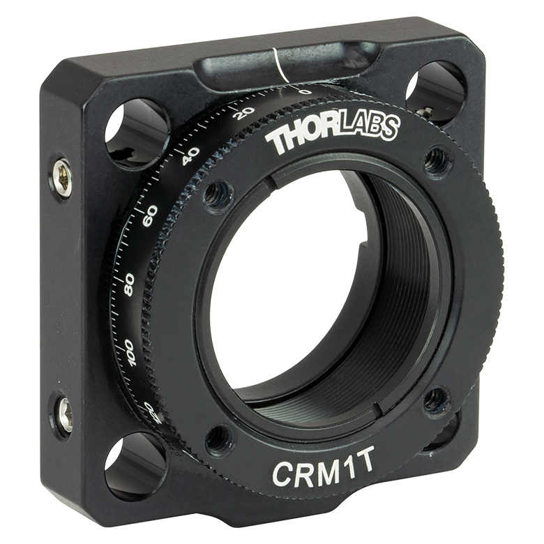
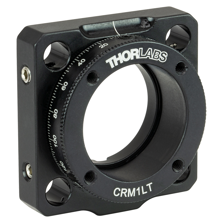
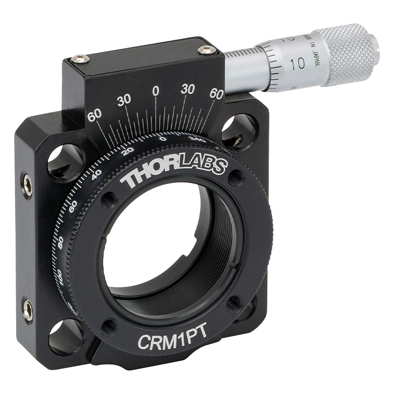
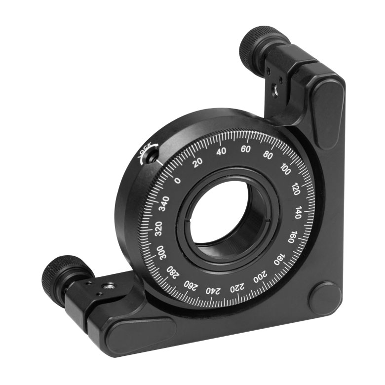
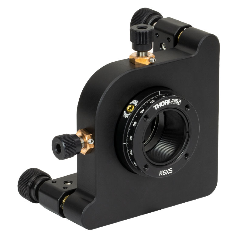
CRM1T(/M) | CRM1LT(/M) | CRM1PT(/M) | KS1RS | K6XS |
| Click Photo to Enlarge |
  |
 |
 |
 |
 |
 |
| Features | Optic Carriage Rotates Within Mounting Ring | 30 mm Cage-Compatiblea | 30 mm Cage-Compatible for Thick Opticsa |
30 mm Cage-Compatible with Micrometera |
±4° Kinematic Tip/Tilt Adjustment Plus Rotation | Six-Axis Kinematic Mounta |
| Additional Details | ||||||
| Rotation Mounts for Ø2" Optics | |||||||
|---|---|---|---|---|---|---|---|
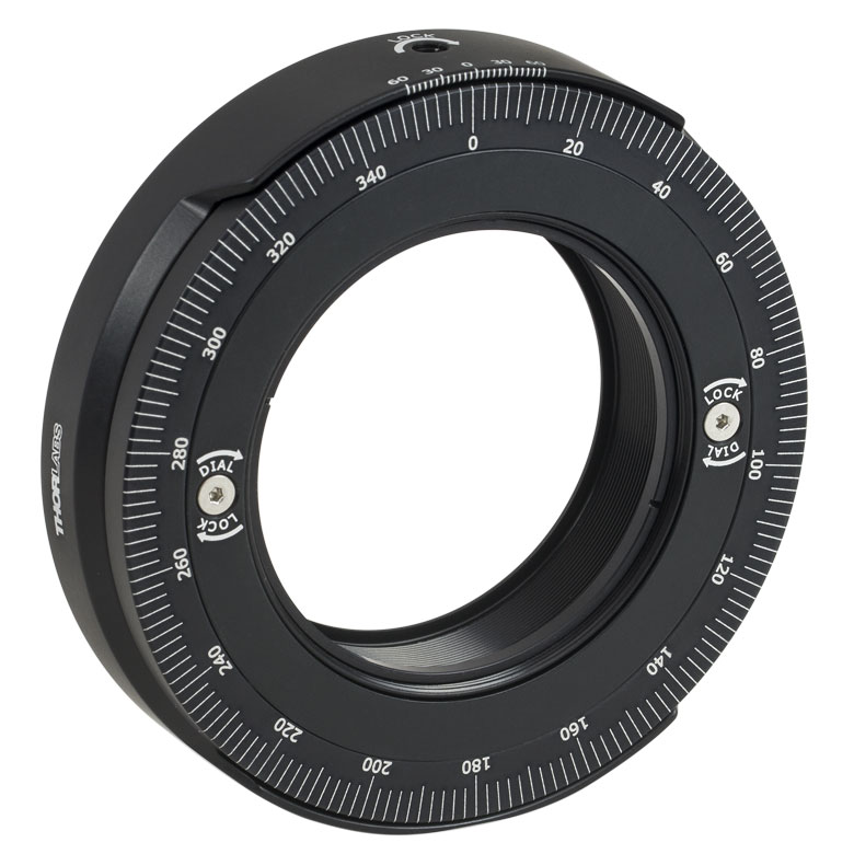
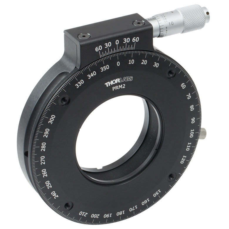
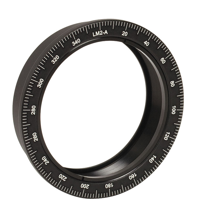
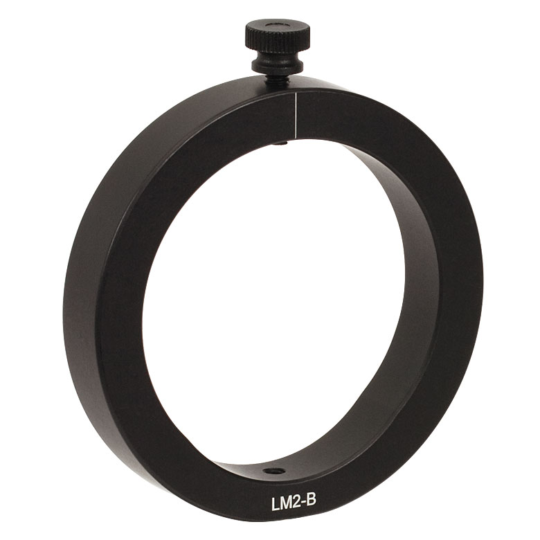
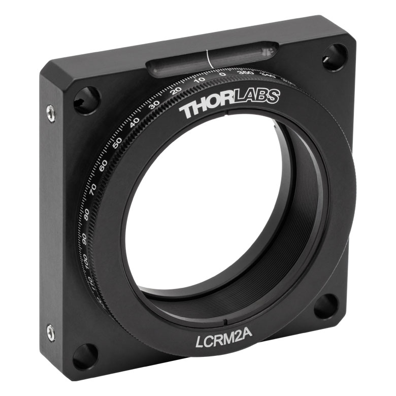
| Item # | RSP2(/M) | RSP2D(/M) | PRM2(/M) | LM2-A & LM2-B(/M) |
LCRM2A(/M) | KS2RS | K6X2 |
| Click Photo to Enlarge | 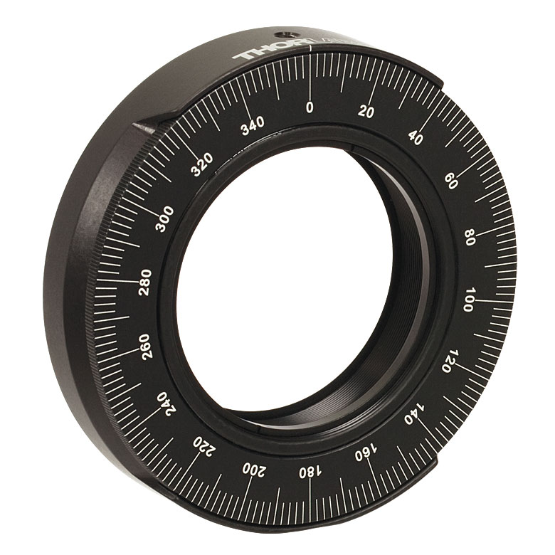 |
 |
 |
  |
 |
 |
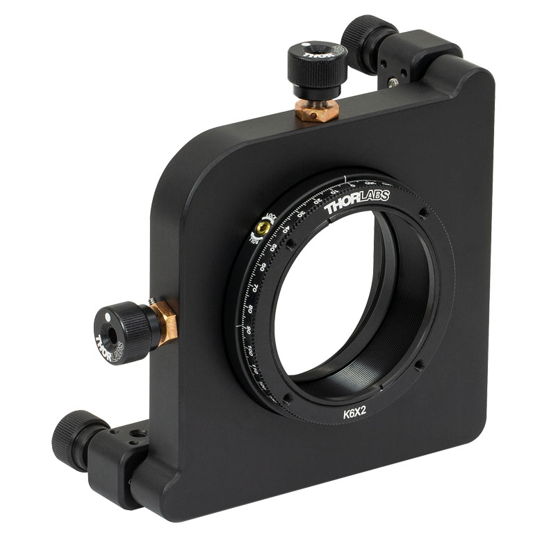 |
| Features | Standard | Adjustable Zero |
Micrometer | Optic Carriage Rotates Within Mounting Ring | 60 mm Cage-Compatible | ±4° Kinematic Tip/Tilt Adjustment Plus Rotation | Six-Axis Kinematic Mount |
| Additional Details | |||||||
Manual Rotation Stages
| Manual Rotation Stages | ||||||
|---|---|---|---|---|---|---|
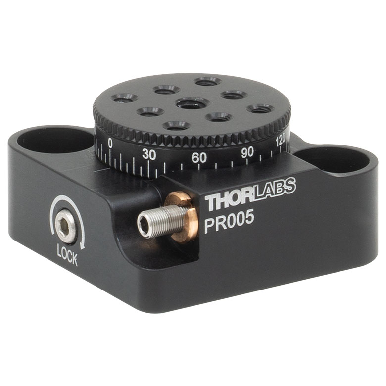
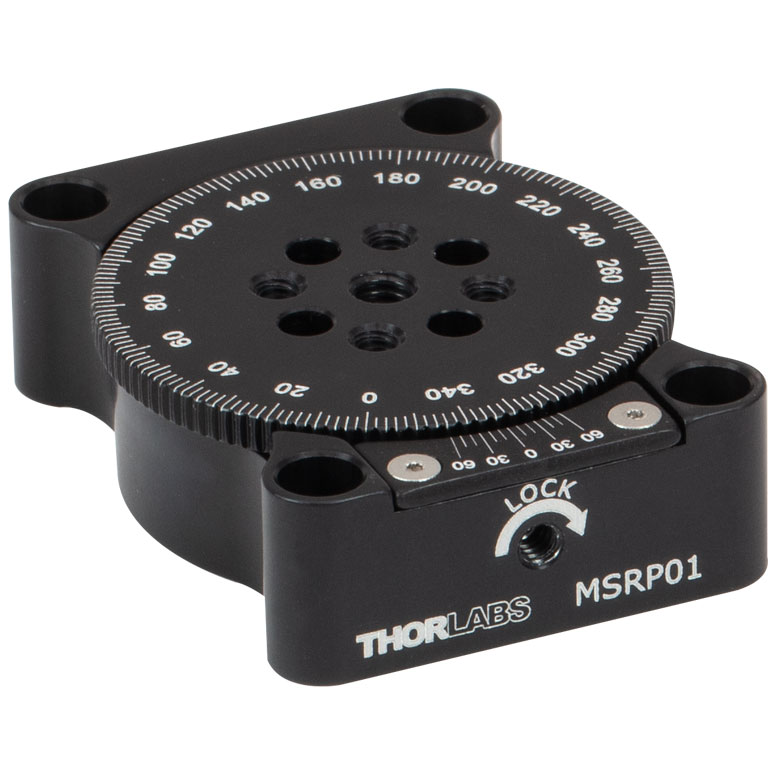
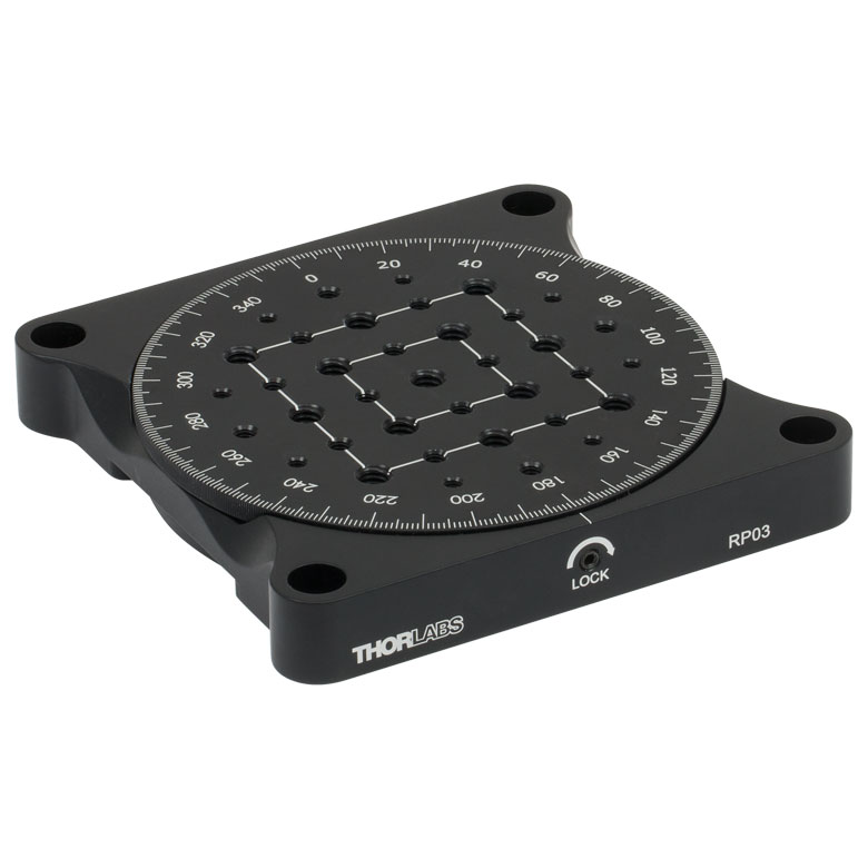
| Item # | RP005(/M) | PR005(/M) | MSRP01(/M) | RP01(/M) | RP03(/M) | QRP02(/M) |
| Click Photo to Enlarge |
 |
 |
 |
 |
 |
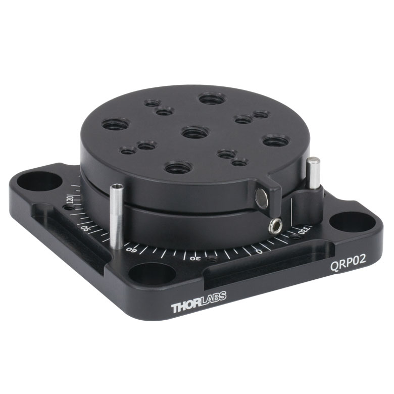 |
| Features | Standard | Two Hard Stops | ||||
| Additional Details | ||||||
| Manual Rotation Stages | ||||||
|---|---|---|---|---|---|---|
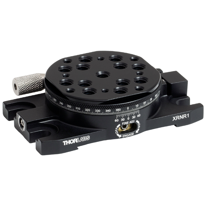
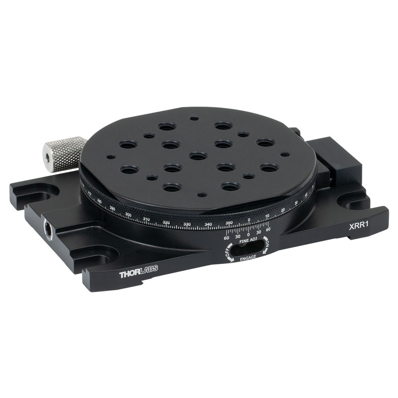
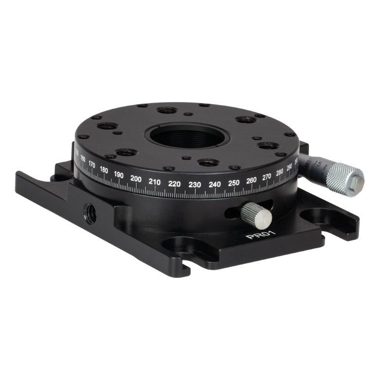
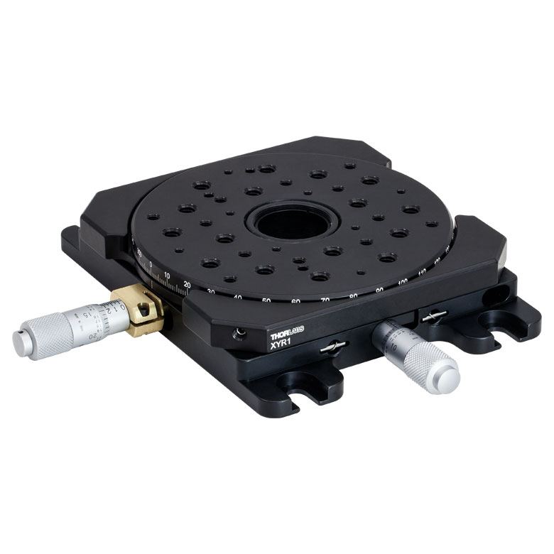
| Item # | XRNR1(/M) | XRR1(/M) | PR01(/M) | CR1(/M) | XYR1(/M) | OCT-XYR1(/M) |
| Click Photo to Enlarge |
 |
 |
 |
 |
 |
 |
| Features | Fine Rotation Adjuster and 2" Wide Dovetail Quick Connect |
Fine Rotation Adjuster and 3" Wide Dovetail Quick Connect |
Fine Rotation Adjuster and SM1-Threaded Central Aperture |
Fine Pitch Worm Gear | Rotation and 1/2" Linear XY Translation | |
| Additional Details | ||||||
Motorized Rotation Mounts and Stages
| Motorized Rotation Mounts and Stages with Central Clear Apertures | |||||
|---|---|---|---|---|---|
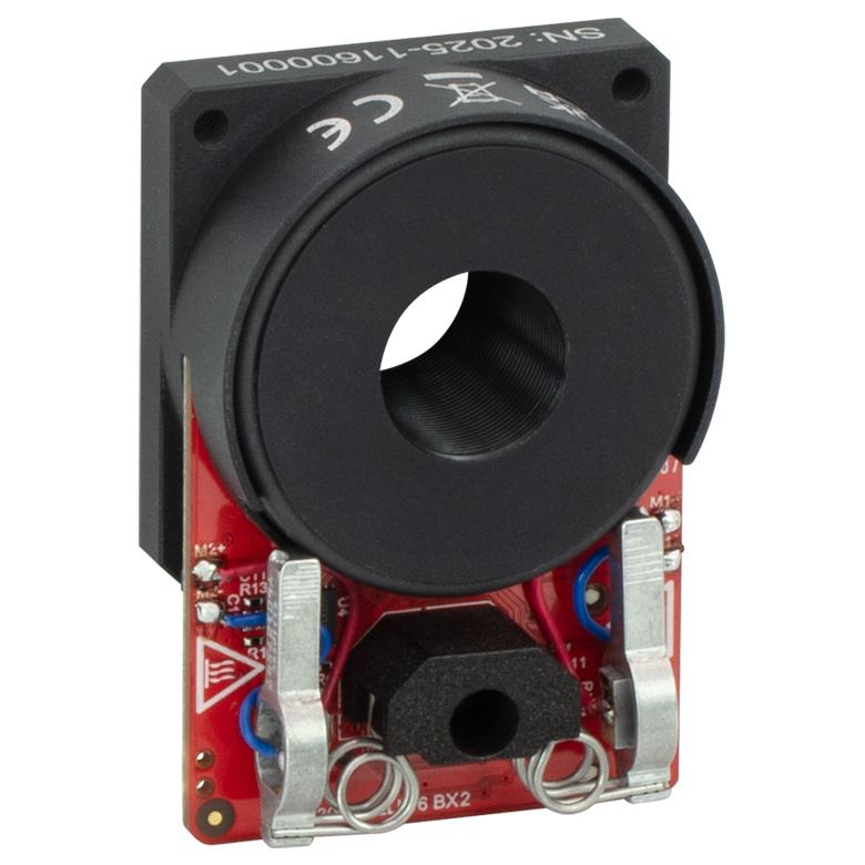
| Item # | DDR25(/M) | PDR1C(/M) | PDR1(/M) | PDR1V(/M) | PDXR1(/M) |
| Click Photo to Enlarge |
 |
 |
 |
 |
 |
| Features | Compatible with SM05 Lens Tubes, 16 mm Cage System, & 30 mm Cage System |
Compatible with 16 mm Cage System |
Compatible with SM05 Lens Tubes & 30 mm Cage System |
Vacuum-Compatible; Also Compatible with SM05 Lens Tubes & 30 mm Cage System |
Compatible with SM05 Lens Tubes & 30 mm Cage System |
| Additional Details | |||||
| Motorized Rotation Mounts and Stages with Central Clear Apertures | |||||||
|---|---|---|---|---|---|---|---|
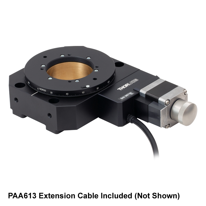
| Item # | K10CR1(/M) | PRM1Z8(/M)a | DDR100(/M) | ELL16 | ELL14 | ELL21(/M) | HDR50(/M) |
| Click Photo to Enlarge |
 |
 |
 |
 |
 |
 |
 |
| Features | Compatible with SM1 Lens Tubes & 30 mm Cage System | Compatible with SM1 Lens Tubes, 16 mm Cage System, 30 mm Cage System |
Compatible with SM05 Lens Tubes, Open Frame Design for OEM Applications |
Compatible with SM1 Lens Tubes, Open Frame Design for OEM Applications |
Compatible with SM2 Lens Tubes, Open Frame Design for OEM Applications |
Compatible with SM2 Lens Tubes |
|
| Additional Details | |||||||
| Motorized Rotation Mounts and Stages with Tapped Platforms | ||
|---|---|---|
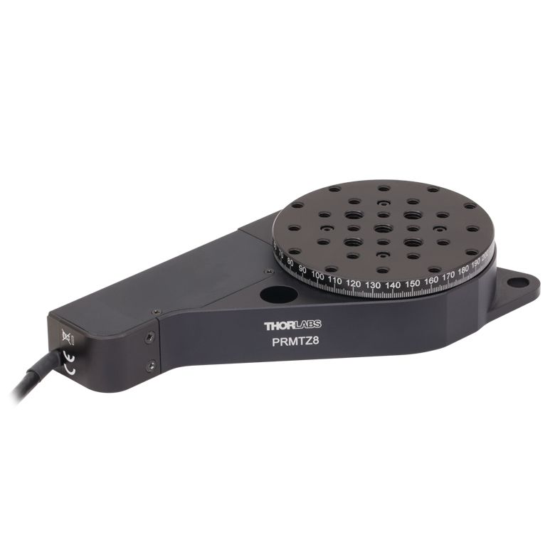
| Item # | PRMTZ8(/M)a | ELL18(/M)b |
| Click Photo to Enlarge |
 |
 |
| Features | Tapped Mounting Platform for Mounting Prisms or Other Optics | Tapped Mounting Platform, Open Frame Design for OEM Applications |
| Additional Details | ||

 Zoom
Zoom
Click for Details
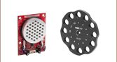
PDR1C(/M) Rotation Stage Features
Dimensions for the metric stage are given in parentheses.
Includes:
- Rotation Stage with Integrated Cable, Female SMC Connector
- Two 2-56 (M2 x 0.4) Cap Screws, 4 mm Long
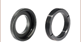
- Two Ø2 mm Dowel Pins
- Continuous 360° Rotation at Speeds Up to 100°/s When Driven with the PDXC or PDXC2 Controller
- Typical Step Size: 30 µrad When Driven with the PDXC or PDXC2 Controller
- Platform Size: Ø1.10" (Ø28.0 mm)
- Platform Height: 18.0 mm
- Compact Footprint: 30.0 mm x 30.0 mm
- Integrated 1 m (3.3 ft) Cable with Female SMC Connector
- Requires a PDXC, PDXC2, KIM001, or KIM101 Piezo Controller (Sold Separately Below)
The PDR1C(/M) ORIC® Open-Loop Piezo Inertia Compact Rotation Stage can operate at speeds up to 100°/s with no backlash and with a typical step size of 30 µrad when driven with the PDXC or PDXC2 controller; when driven with the KIM001 or KIM101 controllers, the stage can operate at speeds up to 30°/s and a typical step size of 150 µrad. The piezo inertia drive is self-locking when the stage is at rest and no power is supplied to the piezo. These features make the PDR1C(/M) stage ideal for set-and-hold applications that require resolutions smaller than a milliradian and long-term alignment stability.
Mounting Features
The PDR1C(/M) stage can be mounted vertically or horizontally. Three sides of the stage each have one 8-32 (M4 x 0.7) tapped hole for mounting to a Ø1/2" post. We recommend using SS8S038 (SS4MS10) setscrews when mounting the stage on a Ø1/2" post to not exceed the depth of these holes (3.5 mm [0.14"]). Two #2 (M2) mounting slots, located on opposite corners of the stage, can be used to mount the stage to a flat, even surface (flatness ≤5 μm is recommended) or to one of our ORIC 20 mm linear stages when constructing an XY + rotation configuration.
The rotating top plate features four 8-32 (M4 x 0.7) threaded holes, four 4-40 threaded holes for compatibility with 16 mm cage systems, and a 1/4"-20 (M6 x 1.0) thru hole in the center for mounting optomech or for applications that require an optical path to pass through the body of the stage; the clear aperture of the center hole is Ø0.19" (Ø4.9 mm).
Compatible Accessories
The PD1B(/M), PD1B2(/M), PD1U(/M), and PD1B3(/M) adapter plates each provide a flat surface for mounting the PDR1C(/M) stage; each plate also offers a unique variety of additional mounting features. The PD1T(/M) adapter plate can be mounted below the PDR1C(/M) stage and features a central 8-32 (M4 x 0.7) tapped hole for post mounting. The PD1Z(/M) right-angle bracket allows the PDR1C(/M) stage to be mounted in an XY+θY rotation configuration.
Each stage has an integrated 1.0 m cable; the PAA101 1.5 m SMC extension cable and T5026 male-to-male SMC adapter can be used to extend the cable length. Due to the capacitance of the cables, please note that the total length of the control cable should not exceed 2.5 m.
Required Controller
A PDXC Piezo Inertia Stage Controller, PDXC2 Compact Piezo Inertia Stage Controller, KIM001 Single-Channel K-Cube® Piezo Inertia Motor Controller, or KIM101 Four-Channel K-Cube Piezo Inertia Motor Controller, available below, is required to operate this stage; the piezo inertia drive cannot be driven using a standard piezo controller. The PDXC2AD female d-sub to male SMC adapter cable is needed to use this stage with the PDXC2 controller. The KIM101 controller must be the 2019 or newer version and have firmware revision 010004 or higher installed. Earlier versions of this controller or those with older firmware will not function properly and may cause failure of the stage and/or the controller. The previous-generation TIM101 controller is not compatible. The specifications for this stage were measured using the PDXC and PDXC2 benchtop controller and the KIM101 K-Cube controller; the KIM001 controller provides similar performance to the KIM101 controller. Since the PDXC and PDXC2 operate at higher frequencies but output a lower maximum voltage than the K-Cube controllers, they can drive the PDR1C(/M) stage at a higher speed with a smaller step size and lower driving torque.
Note: During operation, the stage makes a high-pitch noise and may generate some heat. This is normal behavior in the performance of the device and does not indicate a fault condition.

 Zoom
Zoom
Click for Details
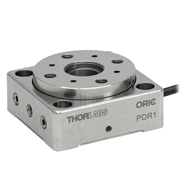
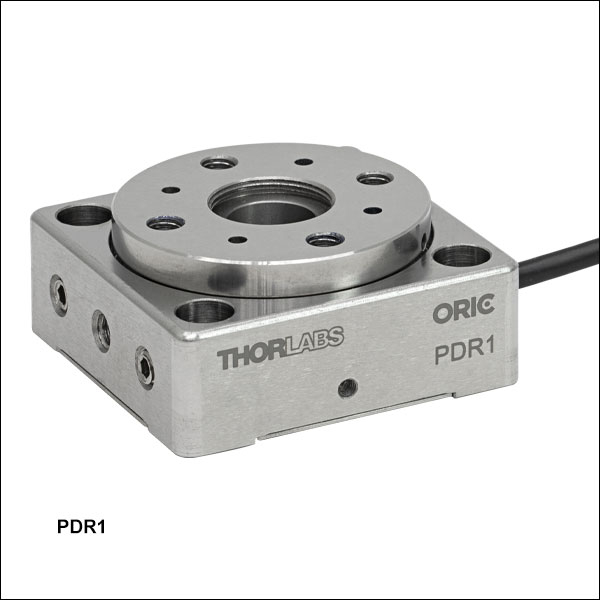
PDR1(/M) Rotation Stage Features
Dimensions for the metric stage are given in parentheses.
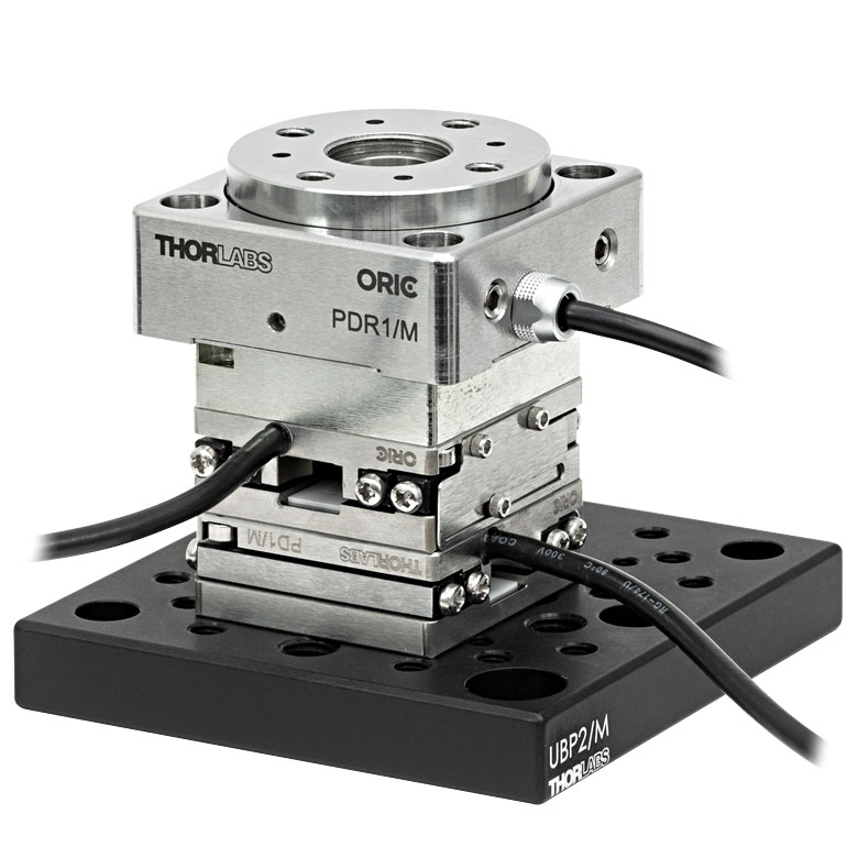
Click to Enlarge
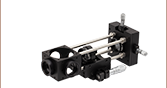
XY + rotation stage created by mounting a PDR1(/M) rotation stage on two PD1(/M) 20 mm travel linear stages. Two 5/16" (8 mm) long, 8-32 (M4 x 0.7) screws are required to mount the bottom PD1(/M) stage to the UBP2(/M) base.
Click to Enlarge
XY + Rotation Stage created by mounting two PD1(/M) linear stages on a PDR1(/M) rotation stage using the included accessories. Note that the cables from the PD1(/M) stages will limit the rotation in this configuration.
- Continuous 360° Rotation at Speeds Up to 20°/s
- Typical Step Size: 250 µrad
- Platform Size: Ø1.34" (34.0 mm)
- Platform Height: 18.0 mm
- Small Footprint: 40.0 mm x 40.0 mm
- Integrated 1 m (3.3 ft) Cable with Female SMC Connector
- Requires a KIM001 or KIM101 Piezo Controller (Sold Separately Below)
The ORIC® Open-Loop Piezo Inertia Rotation Stage can operate at speeds up to 20°/s with no backlash and with a typical step size of 250 µrad. The piezo inertia drive is self-locking when the stage is at rest and no power is supplied to the piezo. These features make the PDR1(/M) stage ideal for set-and-hold applications that require resolutions smaller than a milliradian and long-term alignment stability.
Mounting Features
The PDR1(/M) stage can be mounted vertically or horizontally. Ø6 mm through holes at each corner accept ER cage rods, allowing the rotation stage to be incorporated into a 30 mm cage system, mounted on our ORIC 50 mm linear stage using a PD3T(/M) adapter plate, or mounted to a breadboard using a PD1B3(/M) universal mounting adapter (sold below). The rods are secured in place with 5/64" (2.0 mm) hex setscrews. Additionally, two sides of the stage each have one 8-32 (M4 x 0.7) tapped hole for mounting to a Ø1/2" post.
The bottom of each stage has two 8-32 (M4 x 0.7) tapped holes spaced 1" (25.0 mm) apart that can be used to mount the stage to a flat, even surface or to one of our ORIC 20 mm linear stages when constructing an XY + rotation configuration. Note that when mounting the stage using these holes, the mounting surface must have a flatness of ≤20 µm.
The rotating top plate features four 8-32 (M4 x 0.7) holes and four holes for Ø2 mm dowel pins that can be used for mounting components or an ORIC linear stage. Thorlabs also offers replacement dowel pins in packs of 20 below. SM05 (0.535"-40) internal threads in the center of the top plate surround a Ø9 mm (0.35") bore through the center of the stage, enabling applications that require an optical path to pass through the body of the stage.
Compatible Accessories
The UBP2(/M) adapter plate features a central 1/4" (M6) slot, four 4-40 tapped holes spaced for 30 mm cage systems, and an array of additional mounting holes. The PD1U(/M) adapter plate provides a convenient means of mounting a PDR1(/M) rotation stage on top of a PD1(/M) linear translation stage.
Each stage has an integrated 1.0 m cable; the PAA101 1.5 m SMC extension cable and T5026 male-to-male SMC adapter can be used to extend the cable length. Due to the capacitance of the cables, please note that the total length of the control cable should not exceed 2.5 m.
Includes:
- Rotation Stage with Integrated Cable, Female SMC Connector
- Two 8-32 (M4 x 0.7) Cap Screws, 5.3 mm Long
- Two Ø2 mm Dowel Pins
Required Controller
A KIM001 Single-Channel K-Cube® Piezo Inertia Motor Controller or KIM101 Four-Channel K-Cube Piezo Inertia Motor Controller, available below, is required to operate these stages; the piezo inertia drives cannot be driven using a standard piezo controller. The KIM101 controller must be the 2019 or newer version and have firmware revision 010004 or higher installed. Earlier versions of the controller or those with older firmware will not function properly and may cause failure of the stage and/or the controller. The previous-generation TIM101 controller is not compatible. The specifications for this stage were measured using the KIM101 K-Cube Controller; similar performance is provided by the KIM001 controller.
Note: During operation, the stage makes a high-pitch noise and may generate some heat. This is normal behavior in the performance of the device and does not indicate a fault condition.

 Zoom
Zoom
Click for Details
Figure 727A PDR1V(/M) Vacuum Rotation Stage Features
Dimensions for the metric stage are given in parentheses.
Includes:
- Rotation Stage with Integrated Cable, Female SMC Connector
- Two 8-32 (M4 x 0.7) Cap Screws, 5.3 mm Long
- Two Ø2 mm Dowel Pins
- Vacuum-Compatible Down to 10-6 Torr
- Continuous 360° Rotation at Speeds Up to 20°/s
- Typical Step Size: 250 µrad
- Platform Size: Ø1.34" (34.0 mm)
- Platform Height: 0.71" (18.0 mm)
- Small Footprint: 1.57" x 1.57" (40.0 mm x 40.0 mm)
- Integrated 0.75 m (2.46 ft) Cable with Bare Leads
- Additional 1.0 m (3.3 ft) Bare Lead-to-SMC Cable Included
- Requires a KIM001 or KIM101 Piezo Controller (Sold Separately Below)
The ORIC® Open-Loop Piezo Inertia Rotation Stage can operate at speeds up to 20°/s with no backlash and with a typical step size of 250 µrad. The piezo inertia drive is self-locking when the stage is at rest and no power is supplied to the piezo. These features make the PDR1V(/M) stage ideal for set-and-hold applications that require resolutions smaller than a milliradian and long-term alignment stability.
This stage is vacuum compatible down to 10-6 Torr. It is recommended that before the unit and any adapter plates are installed in the vacuum chamber, all components are pre-baked to remove volatile compounds and moisture from the unit, which could potentially spoil the vacuum. During the pre-bake, the temperature must be limited to 120 °C. The stage has an integrated 0.75 m long vacuum-compatible cable with flying leads for connecting the actuator to the vacuum chamber bulkhead. The leads are PTFE-coated, 30 AWG wires; the red lead is positive and the white lead is negative. A 1.0 m dual-core cable with an SMC connector is also included.
Mounting Features
The PDR1V(/M) stage can be mounted vertically or horizontally. Ø6 mm through holes at each corner accept ER cage rods, allowing the rotation stage to be incorporated into a 30 mm cage system, mounted on our ORIC 50 mm linear stage using a PD3T(/M) adapter plate, or mounted to a breadboard using a PD1B3(/M) universal mounting adapter (sold below). The rods are secured in place with 5/64" (2.0 mm) hex setscrews. Additionally, two sides of the stage each have one 8-32 (M4 x 0.7) tapped hole for mounting to a Ø1/2" post.
The bottom of each stage has two 8-32 (M4 x 0.7) tapped holes spaced 1" (25.0 mm) apart that can be used to mount the stage to a flat, even surface or to one of our ORIC 20 mm linear stages when constructing an XY + rotation configuration. Note that when mounting the stage using these holes, the mounting surface must have a flatness of ≤20 µm.
The rotating top plate features four 8-32 (M4 x 0.7) holes and four holes for Ø2 mm dowel pins that can be used for mounting components or an ORIC linear stage. Thorlabs also offers replacement dowel pins in packs of 20 below. SM05 (0.535"-40) internal threads in the center of the top plate surround a Ø9 mm (0.35") bore through the center of the stage, enabling applications that require an optical path to pass through the body of the stage.
Required Controller
A KIM001 Single-Channel K-Cube® Piezo Inertia Motor Controller or KIM101 Four-Channel K-Cube Piezo Inertia Motor Controller, available below, is required to operate these stages; the piezo inertia drives cannot be driven using a standard piezo controller. The KIM101 controller must be the 2019 or newer version and have firmware revision 010004 or higher installed. Earlier versions of the controller or those with older firmware will not function properly and may cause failure of the stage and/or the controller. The previous-generation TIM101 controller is not compatible. The specifications for this stage were measured using the KIM101 K-Cube Controller; similar performance is provided by the KIM001 controller.
Note: During operation, the stage makes a high-pitch noise and may generate some heat. This is normal behavior in the performance of the device and does not indicate a fault condition.

 Zoom
Zoom
Click for Details
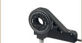
PDXR1(/M) Rotation Stage Features
Dimensions for the metric stage are given in parentheses.
Includes:
- Rotation Stage with Integrated Cable, Female D-Sub Connector
- Two 8-32 (M4 x 0.7) Cap Screws, 16 mm Long
- Two 8-32 (M4 x 0.7) Cap Screws, 8 mm Long
- Two 8-32 (M4 x 0.7) Cap Screws, 5.3 mm Long
- Two 2-56 (M2 x 0.4) Cap Screws, 6 mm Long
- Two 2-56 (M2 x 0.4) Cap Screws, 2 mm Long
- Two Ø2 mm Dowel Pins
- Individual Test Data Certificate
- Open- and Closed-Loop Operation Supported
- Optical Encoder Provides Resolution Up to 0.4365 µrad (0.09 arcsec)
- Continuous 360° Rotation at Speeds Up to 30°/s
- Platform Size: Ø1.96" (49.7 mm)
- Platform Height: 0.91" (23.0 mm)
- Small Footprint: 2.20" x 2.20" (56.0 mm x 56.0 mm)
- Integrated 1.5 m (4.9 ft) Cable with D-Sub Female Connector
- Requires the PDXC or PDXC2 Piezo Inertia Controller (Sold Separately Below)
- Each Stage Individually Tested and Shipped with Test Data Certificate
The PDXR1(/M) ORIC® piezo inertia rotation stage with an optical encoder is able to operate in both open- and closed-loop modes, can support loads up to 1 kg, and operate at speeds up to 30°/s with no backlash. The piezo inertia drive is self-locking when the stage is at rest and no power is supplied to the piezo, making these actuators ideal for set-and-hold applications that require resolutions smaller than a milliradian and long-term alignment stability. See the Specs tab for detailed specifications.
Mounting Features
The PDXR1(/M) stage can be mounted vertically or horizontally. #8 (M4) counterbores at two opposite corners provide compatibility with MSB34 (MSB7510/M) Breadboards, Ø1/2" posts, or Ø1" posts with 8-32 (M4 x 0.7) taps. On the underside of the stage, two 8-32 (M4 x 0.7) threaded mounting holes are available on the opposite corners. Additionally, one side of the stage has a 8-32 (M4 x 0.7) tapped hole for mounting to a Ø1/2" post. The stage should be placed on a surface with flatness ≤5 µm and the corner screws tightened to 0.55 N•m for optimal performance. The PD1B3(/M) (sold below) mounting adapter provides a mounting surface with precise flatness to avoid warping. When mounting the stage on a flat surface with a flatness of >5 µm, such as the high-density breadboards above or an optical table using thread adapters, the recommended screw torque is 0.3 N•m.
The rotating top plate features four 8-32 (M4 x 0.7) holes, four 2-56 (M2 x 0.4) holes, and four holes for Ø2 mm dowel pins that can be used for mounting components or an ORIC linear stage. Thorlabs also offers replacement dowel pins in packs of 20 below. Four 4-40 threaded holes provide compatibility with 30 mm cage systems and SM05 (0.535"-40) internal threads in the center of the top plate surround a Ø9 mm (0.35") bore through the center of the stage, enabling applications that require an optical path to pass through the body of the stage.
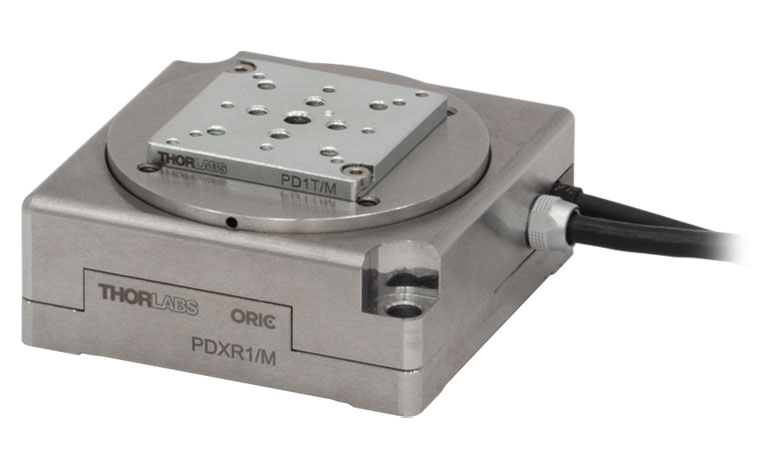
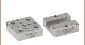
Click to Enlarge
PDXR1 Rotation Stage with PD1T Adapter Plate
Compatible Accessories
The PD1T adapter plate features a central 8-32 tapped hole and sixteen 4-40 tapped holes, four of which are spaced for 16 mm cage systems. The PD1T/M adapter features a central M4 tapped hole, ten M2 x 0.4 mounting taps, four M3 0.5 mounting taps, and four 4-40 taps with 16 mm cage system spacing.
The PD1U adapter plate features four 6-32 and four 8-32 tapped holes in a cross pattern; the PD1U/M adapter features eight M4 tapped holes in the same layout. The bottom surface features five #8 (M4) counterbores.
Each stage has an integrated 1.5 m cable; the PDXCE 3.0 m Extension Cable with a D-Sub connector can be used to extend the cable length. Please note that, due to the capacitance of the cables, do not use cables longer than 4.5 m in total.
Required Controller
The PDXR1(/M) stage is only compatible with the PDXC or PDXC2 controller; it is not compatible with the KIM001 and KIM101 controllers sold on this page.
Note: During operation, the stage may make a high-pitch noise and generate some heat. This is normal behavior in the performance of the device and does not indicate a fault condition.

 Zoom
Zoom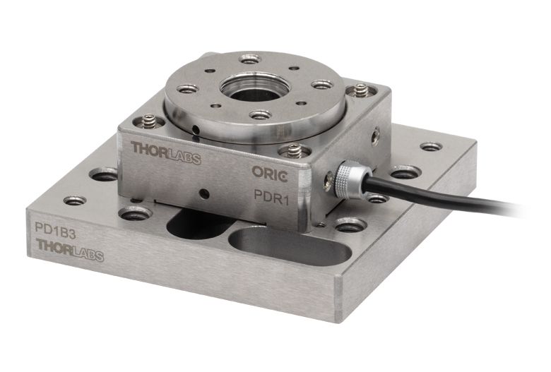

Click for Details
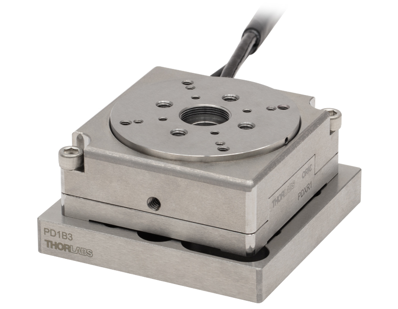
Mechanical Drawing for the PD1B3(/M) Adapter Plate. See the table on the left for descriptions of the hole labels. Dimensions for the metric version of the adapter plate are given in parentheses.
- Provide Flat Surface for Mounting ORIC Stages
- Passivated Stainless Steel Construction
- Reduces Stage Warping When Mounting to Table or Breadboard
- Dimensions (L x W x H): (65.0 mm x 65.0 mm x 10.0 mm)
Thorlabs' PD1B3(/M) Universal Adapter Plate provides a flat surface (flatness ≤5 µm) for mounting any of the ORIC piezo inertia stages. Mounting holes are labeled in the mechanical drawing on the bottom right corresponding to the table below. The four 4-40 threaded holes are 30 mm cage system compatible, and two 1/4"-20 (M6) screws are included for mounting to breadboards.
If the stage is mounted on a surface with >5 µm flatness (as with most breadboards and optical tables), the velocity variation and pitch/yaw of the stage may suffer due to the stage warping. Mounting the stage on the adapter drastically reduces the amount the stage warps when mounted on a table or breadboard with insufficient flatness.
| Labela | Holes/Slots Patternb | Spacingb (Stage Compatibility) | Threading Depth | Places |
|---|---|---|---|---|
| A | 1/4"-20 (M6) | 1" x 2" (25 x 50 mm) | Through | 6 |
| B | Ø2 mm Dowel Pin Holes | 16 x 16 mm | 1.5 mm | 4 |
| C | 4-40 | 30 x 30 mm (Item #s PDR1(/M), PDR1V(/M)) | 3.5 mm | 4 |
| D | 1/4" (M6) Counterbored Slot | 1" to 2" (25 to 50 mm) | N/A | 4 |
| E | 00-90 (M1.2) | 10 x 10 mm (Item #s PD2(/M), PDX2(/M), PDX4(/M)) | 3 mm | 4 |
| F | #8 (M4) Counterbored Slot | 1.25" (31.25 mm) | N/A | 1 |
| G | 2-56 (M2) | 27.0 x 23.4 mm (Item #s PDXZ1(/M), PD1(/M), PD1V(/M), PDX1(/M), PDX1A(/M), PDX1AV(/M), PD1D(/M), PDR1C(/M)) / 40.8 x 30 mm |
7 mm | 8 |
| H | 8-32 (M4) | 2" (50 mm) (Item # PD3(/M)) / 2" x 2" (50 x 50 mm) (Item # PDXR1(/M)) | 7.8 mm | 4 |

 Zoom
Zoom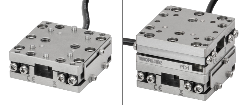
Click for Details
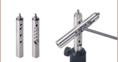
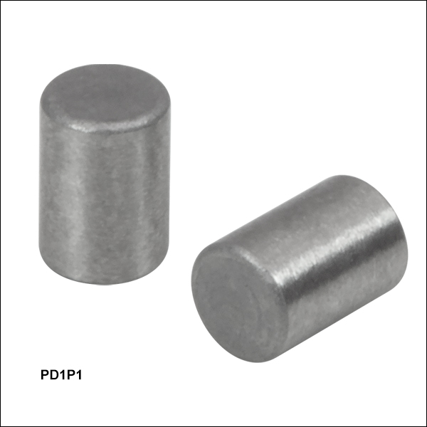
Figure 753A PD1P1 Dowel Pins fit into the mounting holes of most ORIC® Stages, as shown here in the PD1 Stage.
- Ø2 mm, 3 mm Long Dowel Pins
- Corrosion-Resistant Stainless Steel
- Sold in Packs of 20
The PD1P1 Dowel Pins are 2 mm in diameter and are 3 mm long. They serve as replacements for the dowel pins that are included with Thorlabs' 4.5 mm Vertical, 20 mm, 50 mm, Rotating, and Vacuum-Compatible ORIC® Stages. Composed of stainless steel, the dowel pins are corrosion-resistant.
The dowel pins are sold in packs of 20.

 Zoom
Zoom| Key Specificationsa | ||
|---|---|---|
| SMC Port | Number of Ports | Two |
| Voltage | 0 to 40 V | |
| Frequency | 20 kHz Max | |
| D-Sub Port | Number of Ports | One |
| Voltage | -10 to 50 V | |
| Frequency | 20 kHz Max | |
| Max Current Limit | 10 A | |
| Front USB | Type A, USB Host 2.0 | |
| Back USB | Type B, USB Device 2.0 | |
| Voltage of Analog In/Out | -10 to 10 V, ±2% | |
| Voltage of Trigger In/Out | 0 to 5 V, TTL | |
| Input Power | 100 - 240 VAC, 50 - 60 Hz | |
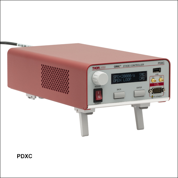
- For complete specifications, please see the manual by clicking the red Docs icon (
 ) below.
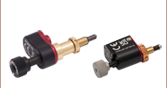
- Controller for ORIC Piezo Inertia Linear Stages, PDXZ1(/M) Vertical Stage, and both PDR1C(/M) and PDXR1(/M) Rotation Stages
- Supports Both Open- and Closed-Loop Operation
- SMC and 15-Pin D-Sub Ports Available
This controller is designed to control our ORIC piezo-inertia-driven linear stages, PDXZ1(/M) vertical stage, and both PDR1C(/M) and PDXR1(/M) rotation stages. It offers two channels that support open-loop stage control using SMC outputs and one channel that can provide open- or closed-loop stage control using a 15-pin D-sub output. If a longer connection is required for ORIC stages with a D-Sub connector, the PDXCE Extension Cable can be used (sold separately below).
Embedded software allows this unit to be fully controlled using the buttons, LCD display, and knob on the front panel. Alternatively, built-in external trigger modes support single-channel operation. By connecting multiple controllers together, multi-channel operation in D-sub mode such as a raster scan is possible. Users can select the output port(s), switch between open-loop and closed-loop modes, and perform homing and encoder calibration without being connected to a PC. In addition to these on-unit controls, USB connectivity provides simple PC-control with our available software platform.
The unit comes with a compatible region-specific power cord. For all applications, use an IEC320 compatible power cord fitted with a plug appropriate for your particular power socket. Ensure the line voltage rating marked on the rear panel agrees with your local power supply.
For more information, please see our full web presentation.

 Zoom
Zoom| Key Specificationsa | ||
|---|---|---|
| Performance Specificationsa | ||
| D-sub Port | Number of Ports | One |
| Voltage | 0 to 56 V | |
| Frequency | 20 kHz Max | |
| Max Current Limit | 10 A | |
| Front USB | Type A, USB HID Host | |
| Back USB | Type B, USB Device 2.0 | |
| I/O Port | Voltage of Analog In/Out | -10 to 10 V, ±2% |
| Voltage of Trigger In/Out | 0 to 5 V, TTL | |
| Ethernet PC Communication | One RJ-45 Port | |
| Dimensions (L x W x H) | 115.2 mm x 150.0 mm x 48.5 mm (4.54” x 5.91” x 1.91”) |
|
| Weight | 0.53 kg | |
| Input Power | 12 V, 3 A DAC | |
- For complete specifications, please see the manual by clicking the red Docs icon () below.
- Controller for ORIC Piezo Inertia Linear Stages, PDXZ1(/M) Vertical Stage, and both PDR1C(/M) and PDXR1(/M) Rotation Stages
- Compact Design and PC Control with Kinesis® Software
- Supports Both Open- and Closed-Loop Operation
- Energy Efficient Switch Amplifier Circuit Outputs Peak Current of 10 A
- Configurable High Speed Communication Interfaces: USB 2.0, Gigabit Ethernet, Digital I/0, Analog I/0
- 800 Hz to 20 kHz Pulse Rate Range
The PDXC2 compact controller is designed for our ORIC piezo-inertia-driven linear stages, PDXZ1(/M) vertical stage, and both PDR1C(/M) and PDXR1(/M) rotation stages. It features one channel that supports open- or closed-loop stage control using a 15-pin D-sub output. The PDXC2AD D-sub to SMC adapter cable (sold below) can be used to operate stages with an SMC connection in open-loop mode.
The PDXC2 controller is connected to PC by either the USB or ethernet ports on the back panel of the controller. All the operating parameters and operations, such as switching between open- and closed-loop modes, performing homing operation, and parameter optimization are controlled by PC with the Kinesis® software (available for download on the Kinesis Software tab). Settings such as trigger modes and movement parameters can be configured for operations such as raster scans. Calibration for specific ORIC stages with encoders (Item #s PDX1(/M), PDX1A(/M), PDX1AV(/M), and PDXR1(/M) only) is performed with the PDXC2 Calibration Tool found on the Motion Control Software page. Please see the user manual for details. Command-line control is also possible through the USB and RS-232 ports.
The PDXC2 unit is powered by the included DS12 12 VDC power adapter, which operates at an input voltage of 100 - 240 VAC and ships with a region-specific AC cable. For all applications, use an IEC320 compatible power cord fitted with a plug appropriate for your particular power socket. Make sure that the line voltage rating marked on the power adapter agrees with your local power supply.
For more information, please see our full web presentation.

 Zoom
Zoom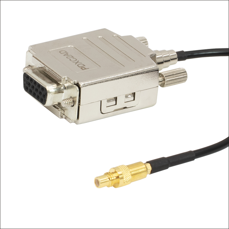
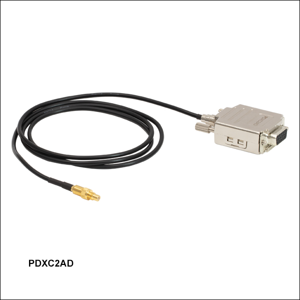
Click for Details
Figure 758B DB15 Female to SMC Male
Click for Details
Figure 758A Mechanical Drawing
- 1 m Long D-Sub to SMC Adapter Cable
- Connects the PDXC2 Controller's D-sub port to the PD1(/M), PD1V(/M), PD1D(/M), or PDR1C(/M) Stage's SMC Connection
The PDXC2AD adapter cable has a female 15 pin D-sub connection and a male SMC connection. The cable adapts the PDXC2 controller's male 15-pin D-sub port to the SMC termination of the PD1(/M), PD1D(/M), PD1V(/M) 20 mm stages, or PDR1C(/M).

 Zoom
Zoom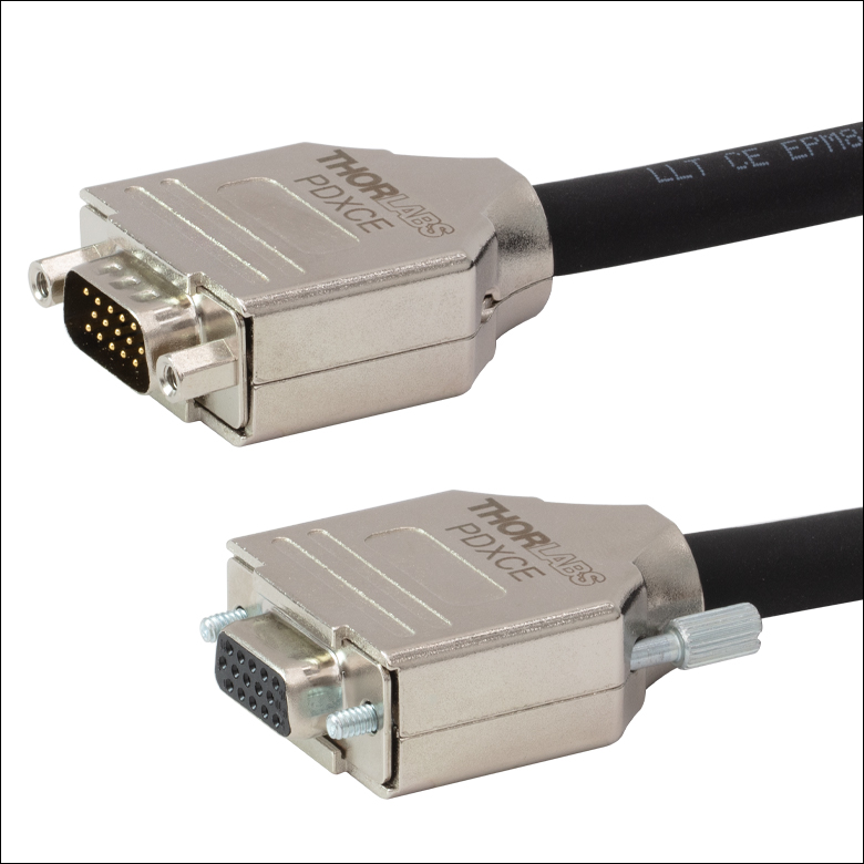
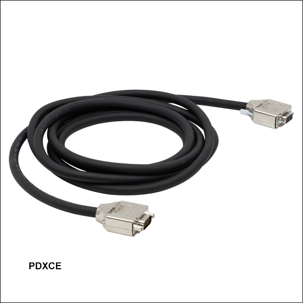
Click to Enlarge
Figure 759B DB15 Male to DB15 Female
Click to Enlarge
Figure 759A Mechanical Drawing
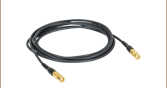
- Connects Female D-Sub Connector on a PDXZ1(/M), PD2(/M), PDX2(/M), PDX4(/M), PDX1(/M), PDX1A(/M), PDX1AV(/M), PD3(/M), PDX3(/M), or PDXR1(/M) Stage to PDXC or PDXC2 Piezo Inertia Stage Controller
- 3000.0 mm (118.11") of Extra Length
The PDXCE extension cable provides 3000.0 mm (118.11") of extra cord length, if needed, when connecting ORIC stages with a Female D-Sub Connector to the PDXC or PDXC2 ORIC Inertia Stage Controllers. Due to the capacitance of the cables, each stage has a recommended maximum cable length. Please check individual stage specifications before adding extension cables.

 Zoom
Zoom| Table 675A Key Specificationsa | ||
|---|---|---|
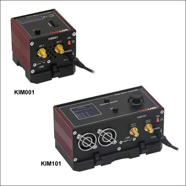
| Item # | KIM001 | KIM101 |
| Piezoelectric Outputs (SMC Male) | One | Four |
| Piezo Output Voltage | 85 to 125 VDC | 85 to 125 VDC per Channel |
| Top Panel Controls | Scroll Wheel | Dual-Axis Joystick |
| External Input (SMA Female) |
±10 V ± 2% | |
| Input Power | +15 VDC @ 2 A | |
| Housing Dimensionsb |
60.0 mm x 60.0 mm x 47.0 mm (2.36" x 2.36" x 1.85") |
121.0 mm x 60.0 mm x 47.0 mm (4.76" x 2.36" x 1.85") |
| Compatible Software | Kinesis | |
| Compatible Piezo Inertia Stagesc |
5 mm Linear Stage, 20 mm Linear Stages, 50 mm Linear Stage, & Rotation Stages |
|
- For complete specifications, please see the manuals by clicking the red Docs icons () below.
- Not Including Mounting Plate
- Compatibility with the PD2(/M) 5 mm and PD3(/M) 50 mm stages require the PD2AD adapter cable. The KIM001 and KIM101 controllers are not compatible with the PDX1(/M), PDX1A(/M), and PDX1AV(/M) Linear Stages with Optical Encoder.
- Compact Footprints
- Adjustable Voltage Output from 85 V to 125 V
- Single-Channel and Four-Channel Versions Available
- Standalone Operation via Top Panel Controls and Display or PC Control via USB Plug and Play
- See Table 675A for Compatible Stages
These compact K-Cube® Controllers provide easy manual and PC control of our piezo inertia stages that use SMC connectors, piezo inertia actuators, and optic mounts. They are also compatible with our PD2(/M) 5 mm or PD3(/M) 50 mm linear stages when used with a PD2AD adapter cable (sold separately). The controllers feature adjustable voltage output from 85 V to 125 V. The top panel display screen enables operation as soon as the unit is turned on, without the need for connection to a PC. Alternatively, both controllers have USB connectivity that provides 'Plug-and-Play' PC-controlled operation with our Kinesis® software package (included).
These units have small footprints and may be mounted directly to the optical table using the 1/4" (M6) counterbored slots in the base plate. Their compact size allows these controllers to be positioned close to the motorized system for added convenience when manually adjusting motor positions using the top panel controls. Tabletop operation also allows minimal drive cable lengths for easier cable management.
KIM001 Single-Channel Controller
This single-channel piezo inertia controller provides a voltage output for a single piezo inertia stage or actuator. The top panel features a spring-loaded scroll wheel for driving the stage or actuator as well as selecting menu options.
KIM101 Four-Channel Controller
This four-channel controller features four SMC outputs to drive piezo inertia devices. The channels can be controlled independently or simultaneously in pairs using the dual-axis joystick on the controller's top panel. The controller can be configured to operate up to four PD series piezo inertia stages, up to four PIA series piezo inertia actuators, or up to two PIM series piezo inertia optic mounts; one KIM101 can only concurrently drive devices that use the same "Select Stage" configuration in the controller's menu options (see the manuals for more details).
For more information, please see the full web presentation.
Operation
Set the stage configuration on the KIM001 or KIM101 controller to "PD(R)" before driving this stage. Select the "Select Stage" option, change it from "PIA" to "PD(R)", and then restart the controller. The display will show "Stage is PD(R)" and the configuration will be changed to drive the ORIC PD Series stage. For additional front panel configuration details, please see the KIM001 or KIM101 controller manuals by clicking the red Docs icons () below. These drivers have an internal sawtooth voltage signal generator capable of sending sub-millisecond pulses (steps) with controllable amplitudes from 85 V to 125 V.
Power Supply
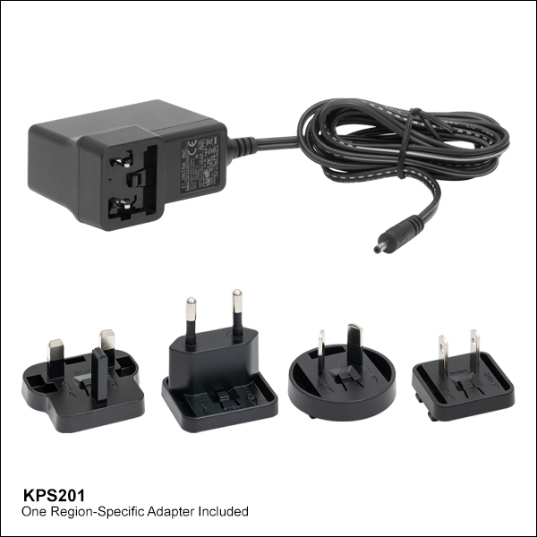
The KIM001 and KIM101 Motor Controllers do not ship with a power supply. The compatible KPS201 Power Supply is sold separately below.
Note: Due to the nature of its design, and its non-linear high frequency switching, the KIM001 and KIM001 units are not compatible with the KCH301 and KCH601 hubs. Only use the KPS201 power supply unit. These controllers are also not compatible with the PDX1(/M), PDX1A(/M), or PDX1AV(/M) stages. Compatibility with the PD2(/M) 5 mm and PD3(/M) 50 mm stages require the PD2AD adapter cable.

 Zoom
Zoom- Power Supply Compatible with KIM001 and KIM101 Motor Controllers
- Universal Input: 100 - 240 VAC
- Region-Specific Adapter Plug Shipped with Power Supply
The KPS201 power supply outputs +15 VDC at up to 2.66 A and can power a single K-Cube® or T-Cube™ with a 3.5 mm jack. It plugs into a standard wall outlet. One region-specific plug adapter, selectable at checkout, is included with each power supply.