 Products Home / Optomechanical Components / Optomechanical Mounts / Optical Mirror Mounts / Motorized Mirror Mounts / Piezoelectric Gimbal Mount
Piezoelectric Gimbal Mount
- True Gimbal Rotation with Up to 30 mrad Angular Range
- Feedback Sensor Output Enables Closed-Loop Operation
- Angular Resolution: 0.05 μrad (Open Loop) or 0.14 μrad (Closed Loop)
- Operated via Included Controller or PC
PGM1SE
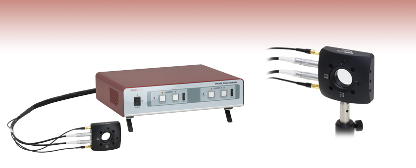
Piezoelectric Gimbal Mount with Included Controller
Piezo Gimbal Mount on Ø1/2" Post


Please Wait
| Key Specificationsa | |
|---|---|
| Piezo Specifications | |
| Piezo Angular Range | 30 mrad ± 15% (Open Loop) 20 mrad (Closed Loop) |
| Angular Resolution | 0.05 µrad (Open Loop) 0.14 µrad (Closed Loop)b |
| Piezo Control Voltage | -25 to 150 V |
| Resonant Frequency (7.0 g Load) |
360 Hz ± 15% |
| Piezo Drive Connectors | Male SMCc |
| Strain Gauge Connectors | Male 7-Pin LEMOc |
| Mechanical Specifications | |
| Optic Size | Ø1.00" (Ø25.4 mm) |
| Optic Thickness | 2 mm (0.08") Min 7.5 mm (0.30") Max |
| Post Mounting Features | 8-32 (M4) Mounting Taps |
| Cage System Compatibility | Four 4-40 Taps for 30 mm Cage Rods |
Applications
- Automatic Precise Laser Beam Steering
- Laser Scanning Microscopy
- LIDAR
- Optical Testing and Sensor Calibration
- Target Acquisition and Tracking
Click to Enlarge
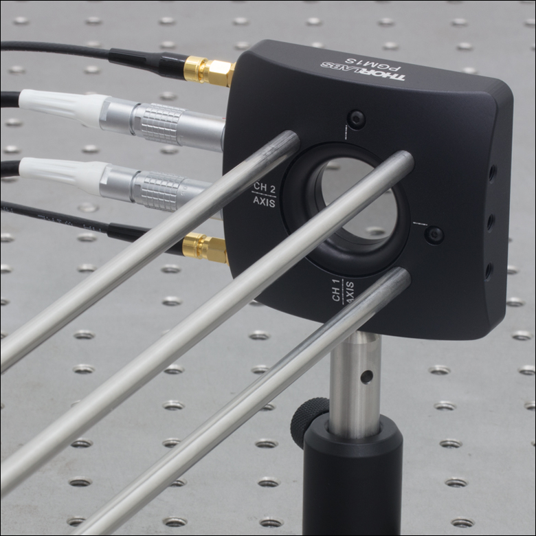
Figure 1.1 Piezoelectric Gimbal Mount with 30 mm Cage Rods
Features
- True Gimbal Rotation Provides Precise Angle Adjustment without Changing Beam Path Length
- High Angular Range of 30 mrad (Open Loop) or 20 mrad (Closed Loop)
- Angular Resolution of 0.05 µrad (Open Loop) or 0.14 µrad (Closed Loop)
- Strain Gauge Feedback Sensors for Closed-Loop Operation
- Includes Individually Calibrated Controller
- Compact Size: 65.0 mm x 81.7 mm x 21.0 mm (2.56" x 3.22" x 0.83")
- SM1-Threaded (1.035"-40) Optic Bore for Ø1" Optics
- 4-40 Tapped Through Holes for Integration with a 30 mm Cage System
- Minimum Piezo Angular Adjustment: 0.1 arcsec (0.5 µrad)
The PGM1SE(/M) Piezoelectric Gimbal Mount has two axes that each rotate the mounted optic about a gimbal axis, keeping the center of the optic in a fixed position. Each axis is capable of scanning over a high piezoelectric angular range of 30 mrad with a resolution of 0.05 µrad in open-loop mode (20 mrad angular range and 0.14 µrad resolution in closed-loop mode). See the Specs tab for complete specifications.
A Ø1" optic can be mounted in the SM1-threaded optic bore and secured with the included SM1 retaining ring. The mount can hold optics between 2 mm and 7.5 mm thick; the optic is installed via the back of the mount, which keeps the optic surface coincident with the gimbal axes, regardless of the optic thickness. We do not recommend mounting an SM1 lens tube to the threading as it will apply excessive torque to the gimbal element.
Six 8-32 (M4) tapped holes on the optic mount allow it to be mounted on a Ø1/2" post. Additionally, four 4-40 tapped holes around the optic bore on both sides of the mount provide compatibility with 30 mm cage systems.
Each mount is shipped with a piezo controller that has been factory calibrated to the specific mount and supplies a voltage of -25 to +150 VDC. Piezo control is supported through the included Kinesis® GUI, either locally using the paired controller or by using an externally supplied control voltage. See the Software & External Control tab for more details. The controller offers USB and RS-232 interfaces for computer control, a BNC input for the addition of external drive signals, and a BNC output that gives either positioning feedback from the mount’s built-in capacitive sensors or a signal proportional to the piezo drive voltage. In addition, a DB15 connector provides signals that can be used for synchronization with external equipment. A USB 2.0 (A to B) cable is included.
| Mount Specifications | |
|---|---|
| Piezo Specifications | |
| Open Loop Angular Scanning Range | 30 mrad ±15% |
| Closed Loop Angular Scanning Range | 20 mrad |
| Bidirectional Repeatabilitya | 0.32 mrad |
| Bidirectional Accuracyb | 0.49 mrad |
| Crosstalkc | 0.56 mrad |
| Orthogonality Ch1 (X) to Ch2 (Y) | 1.85° |
| Angular Resolution | 0.05 µrad (Open Loop) 0.14 µrad (Closed Loop)d |
| Resonant Frequency (7.0 g Load) | 360 Hz ±15%e |
| Maximum Load | 50 g (0.11 lbs) |
| Maximum Recommended Operating Bandwidth | 50 Hz |
| Maximum Angle of Incidence | 55° Typicalf |
| Piezo Input Voltage | -25 to +150 V |
| Capacitance (per Axis) | 3.5 µF ±15% |
| Closed Loop Stability | ±5.0 µrad |
| Piezo Drive Connectors | Male SMCg |
| Strain Gauge Connectors | Male 7-Pin LEMOg |
| Mechanical Specifications | |
| Optic Size | Ø25.4 mm (Ø1.00") |
| Clear Aperture | Ø22.9 mm (Ø0.90") |
| Optic Thickness | 2 mm (0.08") Min 7.5 mm (0.30") Max |
| Cage System Compatibility | Four 4-40 Taps for 30 mm Cage Rods |
| Post Mounting Features | 8-32 (M4) Mounting Taps |
| Mechanical Drawing (Click to View) |  |
| Controller Specifications | |
|---|---|
| Piezoelectric Output | |
| Output Voltage | -30 to 150 VDC |
| Output Current | 150 mA |
| Voltage Stability | 100 ppm over 24 hoursa |
| Noise | <0.5 mV RMS (Bandwidth 20 Hz to 100 kHz) |
| Typical Piezo Capacitance | 1 to 10 µF |
| External Input (BNC) | |
| Input Impedance | 10 kΩ |
| Input Voltage | -10 to +10 VDC |
| Absolute Maximum Input Voltage | ±20 VDC |
| Input Voltage for Full Range | 10 VDC ±2% |
| External Output (BNC) | |
| Output Voltage Range | 0 to 10 V (Nominal for Full Range)b |
| Minimum Recommended Load Impedance | 10 kΩ |
| Protection | Protected Against Short Circuit |
| Scaling Factor (HV Monitor) | 1/15 (10 V for a Piezo Voltage of 150 V) |
| User Input/Output (D-Type 15 Pin Female) | |
| 4 Digital Inputs | TTL Levels |
| 4 Digital Outputs | Open Collector |
| Trigger Input | TTL |
| Trigger Output | TTL, 5 V Logic |
| User 5 V | 100 mA Max |
| Input Power Requirements (IEC Connector) | |
| Voltage | 24 VDC ±5% |
| Supply Current | <4 A |
| Protection | Internal Fuse, 4 A Slow Blow |
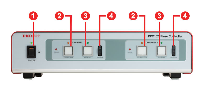
For more information on the controls and connectors on the PPC102 controller, please see the PGM1SE(/M) manual for Kinesis®.
Click to Enlarge
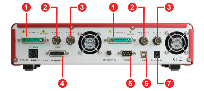
Figure 3.1 Front Panel of the Piezoelectric Gimbal Mount Controller
Click to Enlarge
Figure 3.2 Back Panel of the Piezoelectric Gimbal Mount Controller
| Front Panel Controls | ||
|---|---|---|
| Callout | Label | Description |
| 1 | Power Button and LED | Applies and Removes Power to the Controller |
| 2 | Closed Loop Button and LEDa | Switches the Unit to Closed-Loop Operation |
| 3 | Midpoint Button and LEDa | Moves the Associated Channel to its Midpoint Position Open Loop: Sets Drive Voltage to 60 V Closed Loop: Sets Angular Position to 0 mrad |
| 4 | Position Wheela | Adjusts the Drive Voltage and/or Angular Position |
| Back Panel Controls | ||
|---|---|---|
| Callout | Label | Description |
| 1 | Channel 1 / 2 | Provides the Drive Signal to the Piezo Actuator Connected to the Associated Channel |
| 2 | Monitor 1 / 2 | Used to Monitor the Piezo Actuator on an Oscilloscope or Other Device |
| 3 | Ext In 1 / 2 | Used to Control the Piezo Mount from an External Source Open Loop: -2 to +10 V gives -25 to 150 V Drive Voltage Closed Loop: 0 to +10 V gives ±10 mrad Adjustment |
| 4 | User | Contains a Number of Connections for Programmable Logic Linesa |
| 5 | RS232 | Provides Connection for Serial Port Communication |
| 6 | USB | USB Port for PC Operation |
| 7 | 24 V, 4 A | Power Supply (Included) |
Piezo Mount Pin Diagrams
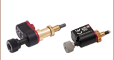
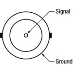
Piezo Drive
SMC Male

Input Voltage: -25 to +150 V
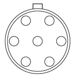
Strain Gauge Feedback
7-Pin LEMO
Piezo Controller Pin Diagrams
Channel 1 / Channel 2 Connectors
| Pin | Description | Pin | Description |
|---|---|---|---|
| 1 | High Voltage Ground (Return) | 8 | HV Ground (Return) |
| 2 | Not Used | 9 | Not Used |
| 3 | Not Used | 10 | Stage IDb |
| 4 | Sine Wave Excitation Output | 11 | Low Voltage Ground |
| 5 | Not Used | 12 | Low Voltage Ground |
| 6 | +15 V (Preamp Supply)a | 13 | Piezo ID (Legacy Stages)b |
| 7 | Low Voltage Ground | 14 | Position Sense Input (Strain Gauge) |
| Coaxial Male |
Position Sense Input (Strain Gauge) |
15 | -15 V (Preamp Supply)a |
| Coaxial Female |
HV Output |
User Connectora
Female DB15
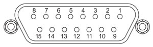
| Pin | Description | Return | Pin | Description | Return |
|---|---|---|---|---|---|
| 1 | Digital Output 1 | 5, 9, 10 | 9 | Digital Ground | - |
| 2 | Digital Output 2 | 5, 9, 10 | 10 | Digital Ground | - |
| 3 | Digital Output 3 | 5, 9, 10 | 11 | For Future Use (Trigger Out) |
5, 9, 10 |
| 4 | Digital Output 4 | 5, 9, 10 | 12 | For Future Use (Trigger In)b |
5, 9, 10 |
| 5 | Digital Ground | - | 13 | Digital Input 4 | 5, 9, 10 |
| 6 | Digital Input 1 | 5, 9, 10 | 14 | 5 V Supply Output | 5, 9, 10 |
| 7 | Digital Input 2 | 5, 9, 10 | 15 | 5 V Supply Output | 5, 9, 10 |
| 8 | Digital Input 3 | 5, 9, 10 |
Computer Control via RS-232
Male DB9
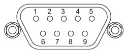
| Pin | Description | Pin | Description |
|---|---|---|---|
| 1 | Not Connected | 6 | Not Connected |
| 2 | RX (Controller Input) | 7 | Not Connected |
| 3 | TX (Controller Output) | 8 | Not Connected |
| 4 | Not Connected | 9 | Not Connected |
| 5 | Ground |
Computer Control via USB
Female Type B USB
External Input
BNC Female
Input Voltage: -10 V to +10 V
Input Impedance: 10 kΩ
External Output
BNC Female
Output Voltage: 0 V to +10 V
Output Impedance: 100 Ω
Minimum Recommended
Output Impedance: 10 kΩ
Software
Kinesis Version 1.14.52
The Kinesis Software Package includes a GUI for control of the Piezo Objective Scanner.
Also Available:
- Communications Protocol

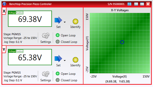
Click to Enlarge
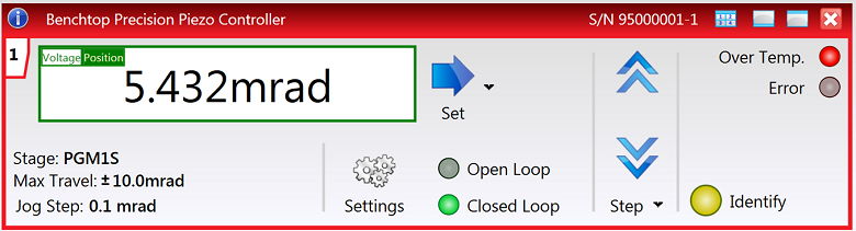
Figure 5.2 Graphical View of Piezo Operation in the Kinesis® GUI
The gimbal mount can be driven using the included standalone Kinesis® GUI or an externally supplied control voltage. Complete details on control are available in the Kinesis manual (PDF link).
Open-Loop Operation vs. Closed-Loop Operation
There are two operating modes for the mount: open loop and closed loop. In open-loop operation, which supports an adjustment range of 30 mrad
± 15%, the user controls the piezo drive voltage (in V). The applied drive voltage corresponds to some amount of angular adjustment. For piezoelectric materials, this displacement does not depend linearly on the applied voltage: it exhibits nonlinearity and hysteresis. It is therefore not straightforward to adjust the mount by choosing the drive voltage. The scanner's built-in capacitive feedback sensors measure the angular position with 0.05 µrad resolution in open-loop operation.
In closed-loop operation, which supports an adjustment range of 20 mrad, the user directly controls the angular position (in mrad). The built-in capacitive feedback sensors measure the objective displacement with 0.14 µrad resolution and automatically adjust the drive voltage in order to correct for inaccuracies in closed-loop operation.
Standalone Kinesis GUI
The Kinesis GUI supports both open- and closed-loop operation. The piezo drive voltage or angular position can be directly typed in or incremented or decremented in fixed, user-defined amounts.

Click to Enlarge
Figure 5.1 Kinesis® GUI Panel During Open-Loop Operation
Click to Enlarge
Figure 5.3 Kinesis® GUI Panel During Closed-Loop Operation
In addition, the GUI enables software-based PID loop tuning. The default settings are designed to provide stable operation in most applications, but fine tuning the PID loop helps account for the specific optics installed in the mount, reducing positional overshoots and ringing about the commanded angular position.
Externally Supplied Control Voltage
An external voltage can be applied using the external input BNC connector on the controller. In open-loop operation, the input voltage range of -2 V to +10 V corresponds to a drive voltage range of -25 V to +150 V, while in closed-loop operation, a the input voltage range from 0 V to +10 V corresponds to ±10 mrad angular adjustment.
DB15 Connector
The DB15 connector on the controller provides several electrical signals that can be used to synchronize the movement of the piezo stage with other equipment. Details on this connector are available in Appendix A.2 of the Kinesis manual (PDF link).
Thorlabs' Kinesis® software features new .NET controls which can be used by third-party developers working in the latest C#, Visual Basic, LabVIEW™, or any .NET compatible languages to create custom applications.
C#
This programming language is designed to allow multiple programming paradigms, or languages, to be used, thus allowing for complex problems to be solved in an easy or efficient manner. It encompasses typing, imperative, declarative, functional, generic, object-oriented, and component-oriented programming. By providing functionality with this common software platform, Thorlabs has ensured that users can easily mix and match any of the Kinesis controllers in a single application, while only having to learn a single set of software tools. In this way, it is perfectly feasible to combine any of the controllers from the low-powered, single-axis to the high-powered, multi-axis systems and control all from a single, PC-based unified software interface.
The Kinesis System Software allows two methods of usage: graphical user interface (GUI) utilities for direct interaction and control of the controllers 'out of the box', and a set of programming interfaces that allow custom-integrated positioning and alignment solutions to be easily programmed in the development language of choice.
For a collection of example projects that can be compiled and run to demonstrate the different ways in which developers can build on the Kinesis motion control libraries, click on the links below. Please note that a separate integrated development environment (IDE) (e.g., Microsoft Visual Studio) will be required to execute the Quick Start examples. The C# example projects can be executed using the included .NET controls in the Kinesis software package (see the Kinesis Software tab for details).
 |
Click Here for the Kinesis with C# Quick Start Guide Click Here for C# Example Projects Click Here for Quick Start Device Control Examples |
|
LabVIEW
LabVIEW can be used to communicate with any Kinesis-based controller via .NET controls. In LabVIEW, you build a user interface, known as a front panel, with a set of tools and objects and then add code using graphical representations of functions to control the front panel objects. The LabVIEW tutorial, provided below, provides some information on using the .NET controls to create control GUIs for Kinesis-driven devices within LabVIEW. It includes an overview with basic information about using controllers in LabVIEW and explains the setup procedure that needs to be completed before using a LabVIEW GUI to operate a device.
 |
Click Here to View the LabVIEW Guide Click Here to View the Kinesis with LabVIEW Overview Page |
|
Click to Enlarge
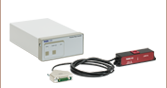
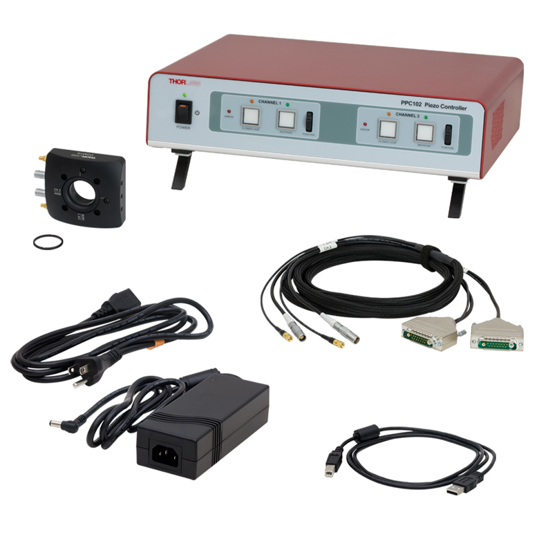
Figure 7.1 Items Included with PGM1SE(/M) (North American Power Cord Shown)
Item # PGM1SE(/M) consists of the following:
- PGM1S(/M) Piezoelectric Gimbal Mount
- PPC102 Piezo Controller
- Dual-Channel Piezo Drive and Strain Gauge Feedback Cable Bundle
- USB 2.0 A-to-B Cable
- Power Supply and Region-Specific Power Cord
| Posted Comments: | |
| No Comments Posted |