 Products Home
Solis® LED Driver
- Plug-and-Play Driver for Thorlabs’ Solis® LEDs
- Three Operating Modes: CW, TTL, and MOD
- Remote Control Operation via USB Interface and Software GUI
- Automatically Sets Current Limit to Protect the LED
DC22
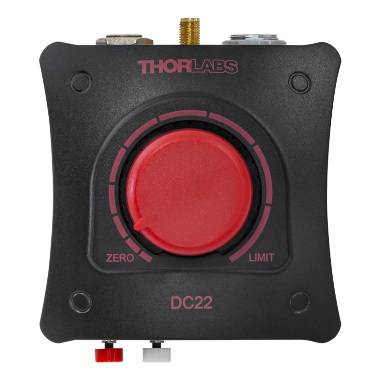
Top View
DC22
Solis LED Driver
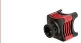
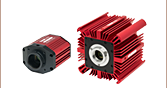
Solis High-Power LED for Microscopy
The DC22 is designed to provide easy plug-and-play operation for Thorlabs’
Solis LEDs.


Please Wait
| Key Specificationsa | |
|---|---|
| Item # | DC22 |
| LED Current (Max)b | 0.1 to 10.0 A |
| LED Forward Voltage (Max)b | 14.0 V |
| LED Current Limit Accuracy | ±(1% + 50 mA) |
| External TTL / Analog Modulation Frequency | DC to 1 kHz |
Click to Enlarge
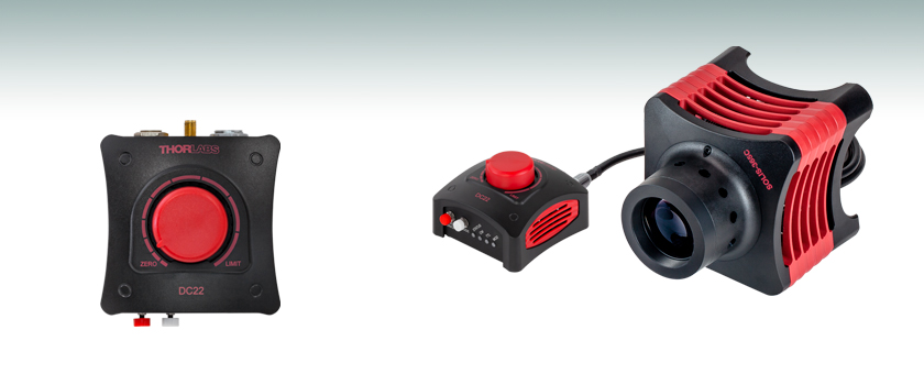
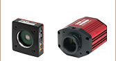
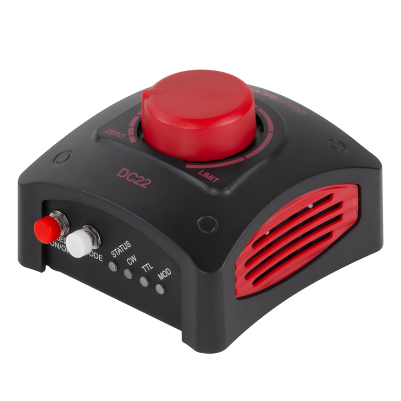
Figure 1.1 DC22 Solis® LED Driver
| Compatible Thorlabs LEDs | |
|---|---|
| Photo (Click for Link) |
 |
| Description | High-Power Solis LEDs |
Features
- Designed for Thorlabs' Solis® LEDs for Microscopy
- Easily Control LED Intensity Using the Dial
- Remote Control Operation via USB Interface and Software GUI
- Protects LED from Overdriving by Automatically Setting the Current Limit
- Provides Drive Current Up to 10.0 A
- Supports LED Forward Voltage Up to 14.0 V
- Supports Three Operating Modes:
- Standalone CW Operation
- External TTL Modulation via SMA Connector
- External Analog Modulation via SMA Connector
Thorlabs' DC22 LED Driver provides a simple way to control any of Thorlabs' Solis LEDs. Easy to set up and use, this driver is an ideal solution for users of our Solis LEDs who don't require the more advanced functions provided by the DC2200 Touchscreen LED Driver. See the Solis LED Drivers tab for a comparison between the DC22 and DC2200 drivers.
For standalone use in CW mode, the current provided to the LED is controlled by turning the knob on the top of the driver. The position on the top panel marked LIMIT will correspond to the maximum LED current for the connected Solis LED, as the driver automatically detects and sets the current limit to the value stored in each Solis LED's internal memory to protect it from being overdriven. Pushing on the knob will either switch the LED on at the percentage of the maximum current indicated by the control knob position or turn it off.
A tri-color LED on the side of the unit indicates the current LED status, including whether the LED is on or off (useful with IR LEDs), whether the LED is operating normally, or if an error has occurred.
Please note that the DC22 driver is designed specifically to work with the internal electronics in Thorlabs' Solis LEDs and should not be used to drive any other type of LED. Thorlabs also offers other LED drivers that are compatible with our mounted, collimated, fiber-coupled, and PCB-mounted LEDs. See Table 1.2 for available LED driver options.
Operating Modes
The CW mode is the default operating mode selected when an LED is connected to the DC22 driver. In this mode, the LED is driven with a constant current set by the rotary knob or specified in the Connection screen within the GUI.
The TTL mode operates by receiving an external active-high voltage signal through the SMA input on the back panel of the driver. A high level corresponding to a voltage of 2.6 - 5.0 V will enable the LED drive current and a low level of 0.0 - 0.8 V will switch the LED drive current off. While the input is in the high (active) state, the brightness of the LED can be controlled via the rotary knob or through the GUI. The maximum guaranteed modulation frequency for the TTL mode is 1 kHz. See the Specs tab for detailed TTL signal requirements.
The DC22 driver can also be operated in an analog modulation (MOD) mode where the output of the LED is controlled via an external voltage input through the same SMA input as the TTL signal. When operating in the MOD mode, a voltage of 0 V corresponds to 0 A drive current (the LED is off) while 5 V corresponds to 10 A drive current with a modulation coefficient of 2 A/V. If the input signal sets the current higher than the limit for the attached LED, the DC22 driver will maintain the limit determined by the LED.
PC Control and Software
The DC22 LED Driver can also be controlled remotely via a USB 2.0 connection on the back of the device and the downloadable Software GUI available here. When a Thorlabs LED with EEPROM technology is connected, the data will be automatically read and the current limit will be set to the maximum. The current limit can then be adjusted in the Settings section of the GUI. Please note that the DC22 Software can control up to 10 LED drivers in parallel.
The Software GUI displays the On/Off status of the LED and the current set point, as well as the drive current and voltage measured by the DC22 driver. The set current and current limit can only be changed in increments of 10 mA. The operating mode can also be selected through the GUI interface. Please see the Software tab or user manual for more details.
Note: If the connected LED is turned off and then back on, the set current will follow the last used interface (GUI or rotary knob). For example, If the last set current was made through the GUI, then the device will follow the GUI set value when turned on regardless of the position of the rotary knob.
| Table 1.2 LED Controller Selection Guide | ||||||
|---|---|---|---|---|---|---|
| Type | Max Number of LEDs |
Max Current |
Modulation Mode | USB | Remote Operation |
Compatible LEDs |
| upLED™ LED Driver | 1 | 1.2 A | - | Yes | Yes | Mounted, Collimated, Fiber Coupled, Diffuse Backlight, and PCB Mounteda |
| Compact T-Cube™ Driver | 1 | 1.2 A | 0 - 5 kHz | No | No | |
| 4-Channel Driver | 4 | 1 A | 0 - 100 kHz | Yes | Yes | |
| 4.0 A LED Driver | 1 | 4.0 A | 0 - 5 kHz | Yes | Yes | |
| Solis® LED Driver | 1 | 10.0 A | 0 - 1 kHz | Yes | Yes | High Power |
| High-Power Touchscreen Driver | 1 | 10.0 A | 0 - 250 kHz | Yes | Yes | High Power, Mounted, Collimated, Fiber Coupled, Diffuse Backlight, and PCB Mounteda |
| Table 2.1 DC22 Specificationsa | ||
|---|---|---|
| Constant Current Mode (CW) | ||
| LED Current (Max)b | 0.1 to 10.0 A | |
| LED Forward Voltage (Max)b | 14.0 V | |
| LED Current Limit Accuracy | ±(1% + 50 mA) | |
| Noise and Ripple (1 Hz to 1 MHz, RMS) | <2 mA (at 1 A over 2 Ω) | |
| TTL Modulation Modec | ||
| Input Impedance | 10 kΩ | |
| Modulation Frequency Range | DC to 1 kHz | |
| Duty Cycle Range | 0.2% to 99.8% (10 Hz) 2.0% to 98.0% (100 Hz) 25.0% to 75.0% (1 kHz) |
|
| Modulation Waveform | Square Wave / PWM (Pulse Width Modulation) | |
| TTL Low Voltage Level | 0.0 V to 0.8 V | |
| TTL High Voltage Level | 2.6 V to 5.0 V | |
| External Modulation Modec | ||
| Input Impedance | 5 kΩ | |
| Modulation Frequency Range | DC to 1 kHz | |
| Maximum Input Voltage | 5.0 V | |
| Modulation Coefficient | 2 A/V | |
| General | ||
| Power Supply | 15.0 VDC | |
| Power Consumption | 69 W (Max) | |
| Operating Temperature Range | 0 to 40 °C | |
| Storage Temperature Ranged | -40 to 70 °C | |
| Dimensions (W x D x H) | 85.4 mm x 93.5 mm x 59.0 mm (3.36" x 3.68" x 2.32") |
|
| Weight | Without Power Supply | 230 g (0.51 lbs) |
| With Power Supply | 505 g (1.12 lbs) | |
| Callout | Description |
|---|---|
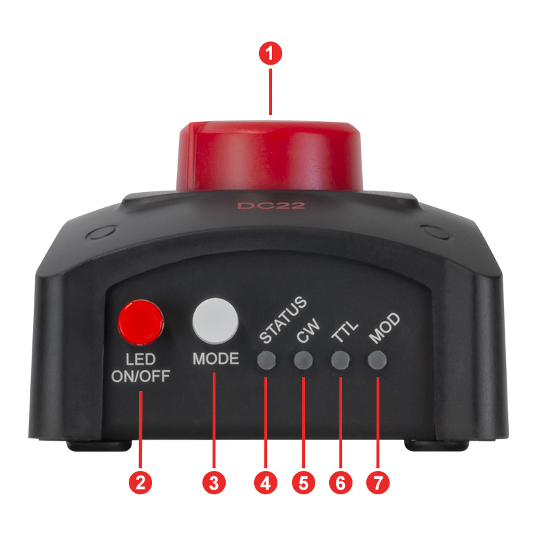
| 1 | Control Knob: Turn for LED Current Adjustment, Push to Turn LED On and Off |
| 2 | Push to Switch the LED On/Off |
| 3 | Mode Selection Button |
| 4 | Status LED Orange: DC22 Ready for Operation, LED Off Green: Solis LED On Red or Blinking: Warning Indicatora |
| 5 | Indicator Light for Continuous Wave (CW) Mode |
| 6 | Indicator Light for External TTL Trigger Mode |
| 7 | Indicator Light for External Modulation (MOD) Mode |
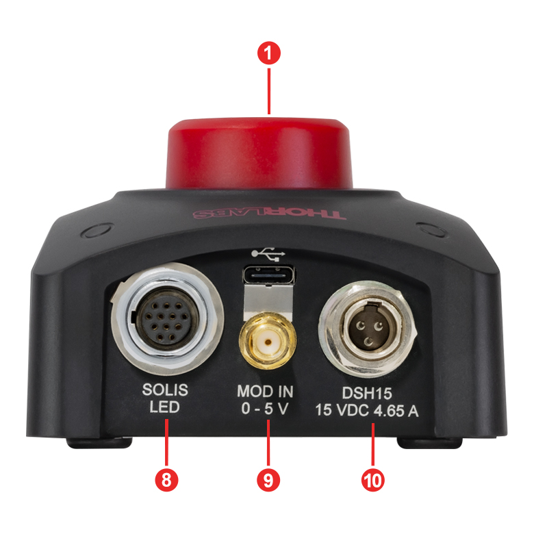
| 8 | Solis® LED Connector |
| 9 | SMA Female Connector, Modulation Input for TTL and MOD Modes |
| 10 | Input for Power Supply |
DC22 Details
Click to Enlarge
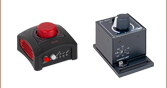
Figure 3.1 Front View of the DC22 LED Driver
Click to Enlarge
Figure 3.2 Back View of the DC22 LED Driver
Click to Enlarge
Figure 3.3 Top View of the DC22 LED Driver
DC22 Connector Pin Diagrams
Solis® LED Connector
12 Pin Neutrik MiniCON Female Connector
The DC22 Driver is only intended for use with Thorlabs' Solis LEDs, so this pin diagram is provided for reference only.
| Pin | Connection | Pin | Connection |
|---|---|---|---|
| 1 | LED Cathode | 7 | LED Anode |
| 2 | LED Cathode | 8 | LED Cathode |
| 3 | Not Used | 9 | LED Cathode |
| 4 | LED Anode | 10 | Not Used |
| 5 | LED Anode | 11 | EEPROM (Data) I/O |
| 6 | LED Anode | 12 | EEPROM (Data) Ground |
External Trigger
SMA Jack for TTL and MOD Signal
Low Voltage: 0.0 to 0.8 V
High Voltage: 2.6 to 5.0 V
Click to Enlarge
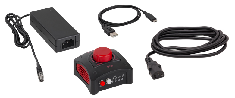
Figure 5.1 Contents Included with the DC22 LED Driver
The following items are included in the DC22 package:
- DC22 LED Current Controller
- 15 VDC Regulated Power Supply with 3-Pin TA3FLX Connector
- Region-Specific Power Cord
- USB 2.0 Type-A to Type-C Cable
| Minimum System Requirements | |
|---|---|
| Operating System | Windows® 10 (32-Bit and 64-Bit), Windows® 11 |
| Processor (CPU) | 1 GHz |
| Memory (RAM) | 5012 MB |
| Hard Drive | 200 MB of Available Disk Space (64-Bit) |
| Graphics Card Resolution | 1280 x 768 |
| Interface | Free USB 2.0 Port |
Software
Software Version 1.1.1 (September 5, 2025)
DC22 Firmware Version 2.7.3 (September 5, 2025)
DC40 Firmware Version 1.9.2 (September 5, 2025)
Click the link below to download the DC22 and DC40 LED Driver Software.
Software for the DC22 and DC40 LED Drivers
This software GUI for the DC22 and DC40 LED Drivers allows for parallel, remote-controlled operation of up to 10 individual DC22 or DC40 LED drivers. The GUI enables the user to turn on and off the LED, precisely input the current limit, adjust the set current, choose the operation mode, and save the settings for later use.
Additionally, the DC22 and DC40 LED Drivers and GUI will recognize when an LED with Thorlabs' EEPROM technology is connected and automatically set the current limit.
The DC40 driver with GUI Software can be used with non-Thorlabs LEDs and Thorlabs LEDs without an EEPROM by using the toggle switch located in the Settings option of the interface and then manually setting the current limit. The DC22 driver is only designed for use with Thorlabs' Solis® LEDs. Please see the user manual for more details.
The available software can be downloaded by clicking on the link in the Software box.
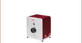
Thorlabs offers two options for driving our Solis® LEDs. The DC22 driver is a basic option that allows users to control the intensity of their LED using a control knob on the top, via an external analog or TTL signal for modulation, or via USB for software control. For more advanced applications, our DC2200 driver provides a touchscreen interface that allows users to control the LED current, select internal or external modulation modes, and more. Table 7.1 provides a comparison of key controller features.
| Table 7.1 Solis® LED Driver Selection Guide | ||
|---|---|---|
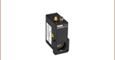
| Item # | DC22 | DC2200 |
| Photo (Click to Enlarge) | 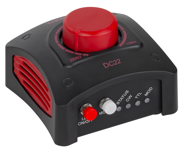 |
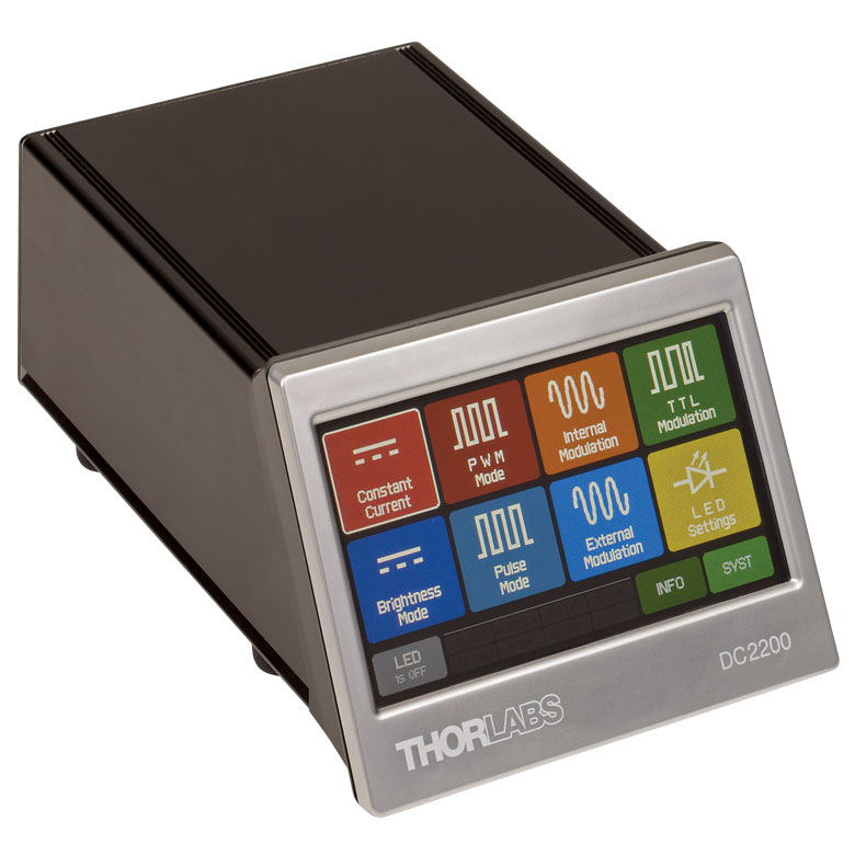 |
| LED Current / Forward Voltage (Max) | 0.1 to 10.0 A / 14.0 Va | 1.0 A / 50.0 Vb 2.0 A / 35.0 Vb 4.0 A / 15.0 Vb 5.0 A / 10.0 Vb 10.0 A / 5.0 Vb |
| Noise and Ripple |
<2 mA (at 1 A over 2 Ω)c | <100 µA from 0.0 to 4.0 Ad <200 µA from 4.0 to 10.0 Ad |
| Internal Modulation Modes | - | 0.1 Hz to 20 kHz (PWMe Mode) 1 µs to 10 s On or Off Time (Pulse Mode) 20 Hz to 100 kHz (Internal Modulation Mode with Sine, Square, Triangle Waveforms) |
| External Modulation (Arbitrary Waveform) |
DC - 1 kHz | DC - 250 kHz [Small Signal Bandwidth (Sine)]f |
| TTL Modulation (External) | DC to 1 kHz (Square Wave, PWMe) | DC to ≥18 kHzg |
| LED Control Interface | Knob to Control LED Current, SMA Port for TTL and External Analog Modulation |
Easy-to-Navigate Touchscreen Interface, Brightness and Constant Current Operating Modes, Internal and External Modulation Modes, SMA Port for External Modulation Accepts TTL Signal or Waveform from a Function Generator, USB Interface for Remote Control |
| Current Limit | Automatically Read and Set from the Solis LED's Internal Memory to Protect the LED from Overdriving | |
| External Software Interface | DC22 and DC40 GUI | DC2200 GUI |
| Other Compatible LEDs | - | Mounted Collimated Fiber Coupled MCPCB Mountedh |
| Posted Comments: | |
先生 黄
(posted 2024-10-15 11:52:56.573) 1、我想知道Turn-Push Knob怎么样才可以拆下来,我希望上电之后,led就可点亮;
2、TTL Modulation Mode,在频率在100hz-1000hz时,led就灭了 hchow
(posted 2024-10-16 03:31:09.0) 你好,黄先生。DC20-SP1 与 DC20 相同。只是安装了不同的固件。它停用了旋转旋钮的按压功能。这意味着只要 DC20 接通电源,LED 指示灯就会有电流流过。电流的大小由旋钮的位置决定。TTL 功能得以保留。我们的中国 Thorlabs 技术支持团队将与您联系。 Mark Handschy
(posted 2023-05-05 06:55:41.193) It would be handy in the specs for the DC20 to indicate what SENSE the TTL control has. We all know what the standard high & low TTL voltage levels are. What we don't know is whether pulling the TTL IN port high turns the lamp on or turns if off. hkarpenko
(posted 2023-05-08 11:42:15.0) Dear Mark,
thank you for your feedback. You are right, we don´t specify this in the specification tab directly on our website. However you can access this information in the more detailed manual we have written for the DC20. On p.8 we explain the modulation application. As long as the TTL input is open or High, the SOLIS is enabled and supplied with the current that is set by the rotary knob. A TTL Low level disables the SOLIS. Per Grön
(posted 2023-05-04 23:08:40.68) Hello,
I am a great fan of Thorlabs, your products are normally great and meet my needs perfectly. Unfortunately, this is not the case for DC20. The product information on your website describes the TTL control option as an alternative to controlling it with the push button "Alternatively, the LED can be modulated using an external TTL signal" but this is not how the product works: You can either turn on the light with the push button, or you can turn it on by first pushing the push button and then using the TTL signal. TTL is not an "alternative" to the push button because it can't be used without it.
I have the SOLIS-1D in a machine in that has many components that are all controlled by a PC. This machine would not be practical to use if each component required the user to manually control it during use, but the DC20 requires just that.
The DC20 is even "smart" enough to not turn on if the push button is pushed at the time of boot so it's impossible to hack around it by always pushing the button, however it is not smart enough to remember the previous setting after a power cycle.
There are so many ways in which the DC20 could have been usable in this application: Make it remember the state on power cycle, use a switch instead of a push button, allow the TTL input to actually turn on the lamp, allow me to physically depress the push button at all times to turn it on... As it is now it seems like I will have to find some other LED driver or to hack the circuit so I can simulate button presses.
This is not helpful design, and the product documentation gets pretty close outright lying about how the TTL feature works. If I would have known that the TTL output does not work without the push button I would not have bought the device.
Kind regards,
Per hchow
(posted 2023-05-05 10:28:20.0) Dear Per Grön, thank you for your valuable feedback. I will let the developers know about the issue you are facing with our DC20. Meanwhile, I will personally reach out to you to find a solution for the problem you have with your DC20. |

 Zoom
Zoom- LED Driver for Thorlabs' Solis® LEDs for Microscopy
- Easily Turn the LED On or Off and Control Current Using the Dial
- Three Operation Modes: CW, TTL, or MOD
- Automatically Set Current Limit by Reading the EEPROM on Solis LEDs
- Remote Control Operation via USB Interface and Software GUI
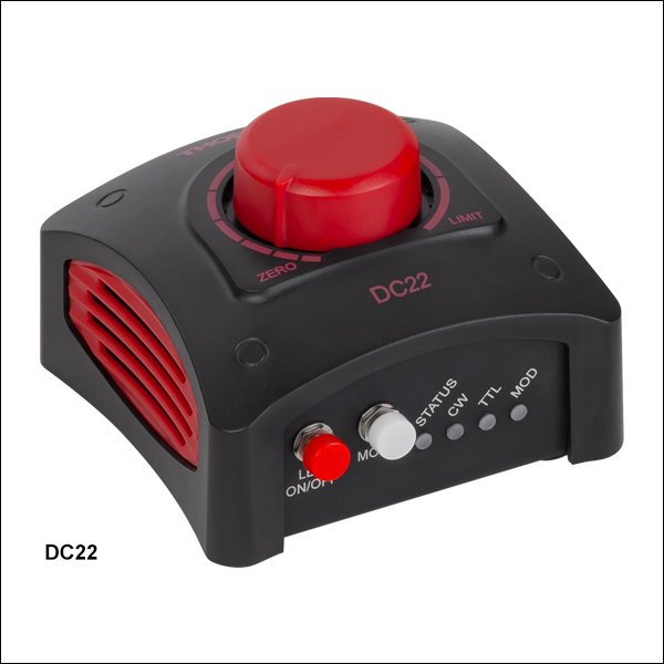
The DC22 LED Driver is a plug-and-play LED driver capable of driving Thorlabs' Solis LEDs for microscopy. This driver features a turn-push knob on the top of the device that turns the connected LED on/off, as well as controls the drive current from 0 A up to the limit specified by the LED's internal EEPROM data.
An LED can be driven in three different operating modes with the DC22 driver: Continuous Wave (CW), Trigger (TTL) Modulation, or MOD mode. Continuous Wave (CW) mode drives the LED with a constant set current; this is the default mode when an LED is connected to the driver. TTL mode can be used to turn the connected LED on and off using an external active-high voltage signal via the SMA input on the back panel. TTL mode can be driven at frequencies up to 1 kHz. In TTL mode the brightness of the LED can be adjusted by turning the turn-push knob. When operated in MOD mode, the LED is controlled by an external voltage. In this mode, 0 V corresponds to off and 5 V corresponds to 10 A, with a modulation coefficient of 2 A/V. If the input signal sets the current higher than the limit for the attached LED, the DC22 driver will maintain the limit determined by the LED.
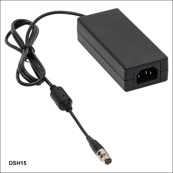
A 15.0 VDC power supply with a region specific power cable is included with each LED driver. If the power supply is damaged or misplaced, it can be replaced with Thorlabs' DSH15 Power Supply, offered below. For a full list of items included with this driver, see the Shipping List tab. Please note that the DC22 driver is designed to work with Thorlabs' Solis LEDs and should not be used to drive any other type of LED.

 Zoom
Zoom
Figure 772A Female TA3FLX
- Compatible with Thorlabs' DC22 and DC40 LED Drivers
- 15 VDC Regulated Power Supply
- 4.65 A Max Current and 69.7 W Output Power
- Female TA3FLX 3-Pin Connector
The DSH15 power supply is a replacement power supply for Thorlabs' DC22 or DC40 LED Drivers, in case the power supply that ships with the device is damaged or misplaced. It is a 15 VDC regulated power with a 1.21 m long cable and a TA3FLX (Mini-XLR), 3-pin female connector. It accepts input voltages from 100 VAC to 240 VAC and ships with a region-specific AC cable.