 Products Home / Drivers & Mounts / Dual Current / Temperature Controllers / Compact Laser Diode Drivers with TECs and Mounts for TO Can Pigtailed LDs
Compact Laser Diode Drivers with TECs and Mounts for TO Can Pigtailed LDs
- Compact, All-in-One Current Sources, Temperature Controllers, and Mounts
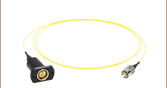
- Compatible with Thorlabs’ Pigtailed TO Can Lasers
- Touch Screen Controlled and Remotely Programmable
CLD1011LP
B, C, and H Pin Codes
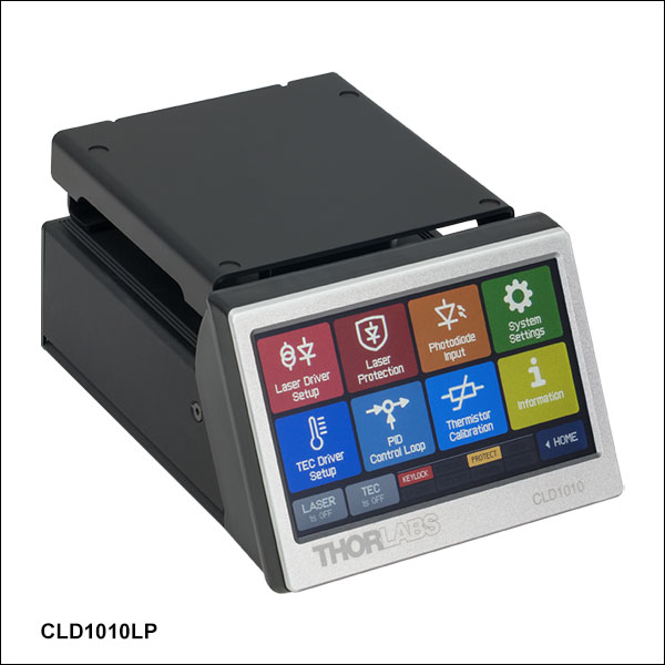
CLD1010LP
A, D, E, and G Pin Codes
Shown with Pigtailed Laser Diode
(Not Included)
Main Operation Panel in Constant Power
Operating Mode


Please Wait

Click to Enlarge
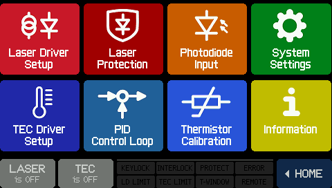
Figure 1.2 Home Screen
Click to Enlarge
Figure 1.1 Menu Screen
Features
- Integrated Mounts Compatible with Thorlabs' Pigtailed TO Can Laser Diodes
- CLD1010LP: Compatible with Pin Codes A, D, E, and G
- CLD1011LP: Compatible with Pin Codes B, C, and H
- Operate in Constant Current or Constant Power Mode
- Controlled Locally with Resistive Touch Screen GUI or Remotely over USB
- Supports Laser Diode Drive Currents up to 1.0 A at 8.0 V
- Temperature-Controlled Laser Operation through Built-In TEC
- Compact Size: 111 mm x 73.5 mm x 169.9 mm (4.37" x 2.9" x 6.69")
- RF Input for Modulating the Laser via an External Source
- Power Supply Included
Click to Enlarge
Figure 1.4 The CLD1010LP shown with the thermal protective cover installed.

Click to Enlarge
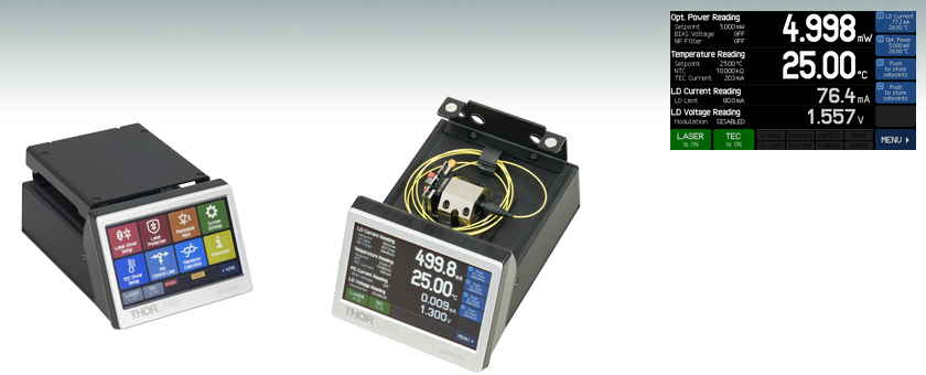
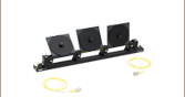
Figure 1.3 A pigtailed laser diode shown mounted in the CLD1010LP.
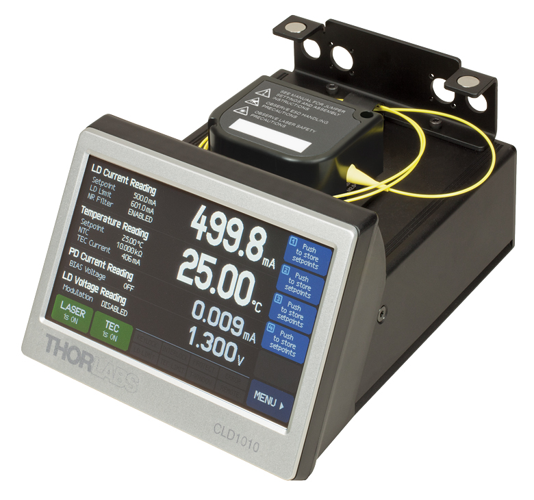
Thorlabs' Compact Laser Diode and Temperature Controllers are complete driver packages designed to drive and cool TO can fiber-coupled laser diodes. The CLD1010LP controller is compatible with A, D, E, and G pin configurations, while the CLD1011LP controller is compatible with B, C, and H pin configurations (see the Pin Diagrams tab for details). These all-in-one units supply up to 1.0 A of drive current, maintain the diode temperature with 0.005 °C of stability over 24 hours, provide a high degree of output stability, and prolong the life of the diode. The controllers also contain a built-in mount for portability and mechanical stability. In additional to a full complement of safety features, such as a soft-start mode, current and temperature limits, and external interlock compatibility, the CLD1010LP and CLD1011LP controllers both include a switchable noise reduction filter and a modulation input. They also each feature an RF Bias-T that allows the laser to be modulated between 200 kHz and 1 GHz with an external RF source (dependent on the specifications of your laser diode). These controllers can be operated in constant current or constant power mode; however, only laser diodes that include a monitor photodiode (pin codes A, B, C, and D) are compatible with constant power mode.
The devices are controlled with built-in 4.3" diagonal, color resistive touch screens, making it easy to tune, tweak, and optimize the laser output parameters. Operating parameters are set using the intuitive menu system, and the user is never more than two taps away from the home screen. A resistive touch screen allows for the screen to be operated when using gloves or other protective equipment. For screenshots of the interface, please see the Display tab. In addition to the touch screen controls, a mini-USB interface on the rear of the unit enables remote control of all settings using several common programming languages, including LabVIEW and the Standard Commands for Programmable Instruments (SCPI) standard. For the full array of options, please refer to the Software tab. When using the CLD1010LP or CLD1011LP to drive a laser, make sure that all of the operating parameters are set within the maximum ratings of your device.
When fully assembled, these compact devices measure just 4.37" x 2.9" x 6.69" (111 mm x 73.5 mm x 169.9 mm), ideal for tightly packed setups. Fiber cables can be fed through the ports on the back of the unit, which are also compatible with Thorlabs' FC-to-FC Mating Sleeves (not included). Two of the holes accept square flange mating sleeves, and two are designed for D-hole mating sleeves. A magnetically sealed lid encloses the laser package in the unit, protecting it from particulates and other lab hazards. A smaller cover that provides thermal protection from the environment can be installed independently of the magnetic lid (see Figure 1.4). Two mounting clips, compatible with 1/4"-20 and M6 bolts, are supplied with each laser diode driver to secure it to a breadboard.
Click to Enlarge
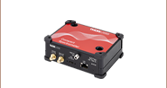
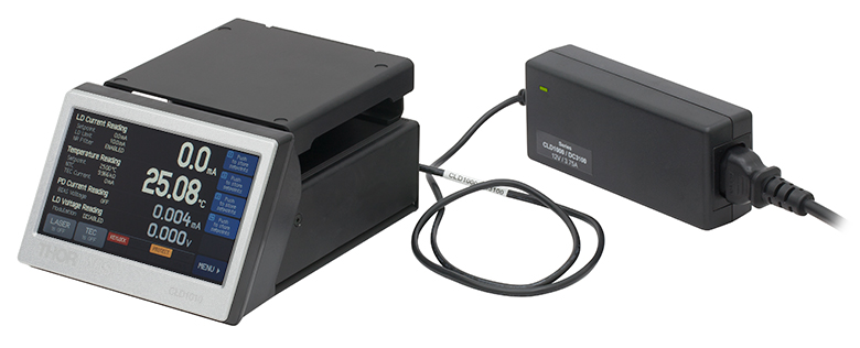
Figure 1.5 These drivers are shipped with a power supply.
Before operating any laser diode with these controllers, please check to ensure that the operating voltage of the intended diode does not exceed the compliance voltage of the controller.
For driver software, as well as programming reference guides for the Programmable Instruments (SCPI) standard, LabVIEW™, Visual C++, Visual C#, and Visual Basic, please see the Software tab.
Thorlabs recommends recalibrating these drivers every 24 months and offers a factory recalibration service. To order this service, scroll to the bottom of the page and select the CAL-CLD.
| Compact LD Driver, TEC, and Mount Selection Guide | ||
|---|---|---|
| Item # | Accepted Package Configurations | Max Drive Current |
| CLD1015 | Type 1 and Type 2 Butterfly Packages | 1.5 A (@ 4 V) |
| CLD1010LP | Pigtailed TO Can Packages with an A, D, E, or G Pin Code | 1.0 A (@ 8 V) |
| CLD1011LP | Pigtailed TO Can Packages with a B, C, or H Pin Code | 1.0 A (@ 8 V) |
Note: These laser diode drivers may be controlled locally via a touch screen or remotely over USB. When controlled locally via the touch screen, the resolution of the laser diode driver is limited by the display; the full resolution can be accessed when the device is controlled remotely. The command sets that are accessible over USB - for example, via LabVIEW or the Standard Commands for Programmable Instruments (SCPI) - offer increased resolution, as shown in Table 2.1.
| Table 2.1 CLD1010LP and CLD1011LP Laser Diode Driver Specifications | ||
|---|---|---|
| Via Front Panela | Via Remote Controla | |
| Current Control (Constant Current Mode) | ||
| Control Range | 0 to 1.0 A | |
| Compliance Voltage | >8 V | |
| Resolution | 100 µA | 50 µA |
| Accuracy | ±(0.1% + 500 µA) | |
| Noise and Ripple (Typical; 10 Hz to 10 MHz, RMS; @ 4.7 Ω Load ) |
10 µA without Noise Reduction Filter 5 µA with Noise Reduction Filter |
|
| Drift (24 Hours, Typical) | <50 µA @ 0 - 10 Hz in Constant Ambient Temperature | |
| Temperature Coefficient | <50 ppm/°C | |
| Current Limit | ||
| Setting Range | 1 mA to 1.0 A | |
| Resolution | 100 µA | 50 µA |
| Accuracy | ±(0.12% + 800 µA) | |
| Photodiode Input | ||
| Photocurrent Rangesb | 0 to 2 mA (Low) 2 to 20 mA (High) |
|
| Photocurrent Resolutionb | 100 nA (Low) 1 µA (High) |
70 nA (Low) 700 nA (High) |
| Photocurrent Accuracyb | ±(0.08% + 0.5 µA) (Low) ±(0.08% + 5 µA) (High) |
|
| Photodiode Reverse Bias Voltage | 0.1 to 6 V | |
| Photodiode Input Impedance | ~0 Ω (Virtual Ground) | |
| Power Control (Constant Power Mode) | ||
| Photocurrent Control Rangesb | 0 to 2 mA (Low) 0 to 20 mA (High) |
|
| Laser Voltage Measurement | ||
| Resolution | 1 mV | 400 µV |
| Accuracy | ±(1% + 80 mV) | |
| Laser Overvoltage Protection | ||
| Trip Voltage (Typical) | 8.2 V | |
| Modulation Input | ||
| Input Voltage (Constant Current Mode) | ±7 V | |
| Input Voltage (Constant Power Mode) | ±10 V | |
| Input Impedance | 10 kΩ | |
| 3 dB Small Signal Bandwidth (Constant Current Mode) |
DC to 300 kHz without Noise Reduction Filter DC to 9.0 kHz with Noise Reduction Filter |
|
| Modulation Coefficient (Constant Current Mode) |
150 mA/V ± 5% | |
| Modulation Coefficient (Constant Power Mode)c |
200 µA/V ± 5% (Low) 2 mA/V ± 5% (High) |
|
| RF Input | ||
| RF Input Impedance | 50 Ω | |
| Small Signal 3 dB Bandwidth | 200 kHz to >1 GHz | |
| Maximum RF Power | 500 mW | |
| Table 2.2 CLD1010LP and CLD1011LP TEC Specifications | ||
|---|---|---|
| Via Front Panela | Via Remote Controla | |
| TEC Current Output | ||
| Control Range | -3.0 to +3.0 A | |
| Compliance Voltage | >4.7 V | |
| Maximum Output Power | >14.1 W | |
| Resolution | 1 mA | 100 µA |
| Accuracy | ±(0.2% + 20 mA) | |
| TEC Current Limit | ||
| Setting Range | 5 mA to 3.0 A | |
| Resolution | 1 mA | 100 µA |
| Accuracy | ±(0.2% + 20 mA) | |
| NTC Thermistor Sensors | ||
| Resistance Measurement Range |
300 Ω to 150 kΩ | |
| Control Rangeb | -55 °C to +150 °C (Max) | |
| Temperature Resolution | 0.01 °C | |
| Resistance Resolution | 1 Ω | |
| Accuracy | ±(0.1% + 1 Ω) | |
| Temperature Stabilityb (24 Hours) |
<0.005 °C (Typical) | |
| Temperature Coefficient | <5 mK/°C | |
| Temperature Window Protection | ||
| Setting Range | 0.01 °C to 100.0 °C | |
| Protection Reset Delay | 0 to 600 s | |
| Table 2.3 CLD1010LP and CLD1011LP General Specifications | |
|---|---|
| Interface | |
| USB 2.0 | Compliant with USBTMC/USBTMC USB488 Specification Rev. 1.0 |
| Protocol | SCPI-Compliant Command Set |
| Supplied Drivers | VISA VXI pnp™, MS Visual Studio™, MS Visual Studio.net™, LabVIEW™, LabWindows/CVI™ |
| General Data | |
| Safety Features | Interlock, Keylock Switch, Laser Current Limit, Soft Start, Short Circuit when Laser Off, Laser Overvoltage Protection, Over Temperature Protection, Temperature Window Protection |
| Display | 4.3" LCD TFT, 480 x 272 Pixels |
| Socket for Laser, Photodiode, NTC, TEC | Pigtailed TO-Can Laser Diodes with A, D, E, or G Pin Codes (Item # CLD1010LP) Pigtailed TO-Can Laser Diodes with B, C, or H Pin Codes (Item # CLD1011LP) |
| Connector for DC Power Input | 2.0 mm Center Pin Connected to + |
| Connector for Modulation Input | SMA |
| Connector for Interlock & Laser On Signal | 2.5 mm Mono Phono Jack |
| Connector for USB Interface | USB Type Mini-B |
| Chassis Ground Connector | 4 mm Banana Jack |
| Desktop Power Supply, Line Voltage, Line Frequency | AC: 100 to 240 V ± 10%, 47 to 63 Hz DC: 12 V ± 5% / 3.5 A |
| Maximum Power Consumption | 40 VA |
| Operating Temperature | 0 to +40 °C |
| Storage Temperature | -40 to +70°C |
| Warm-up Time for Rated Accuracy | 30 min |
| Weight (with Power Supply) | 1.1 kg |
| Weight (without Power Supply) | 0.75 kg |
| Dimensions without Operating Elementsa (W x H x D) | 111 mm x 73.5 mm x 153.3 mm (4.37" x 2.9" x 6.04") |
| Dimensions with Operating Elementsa (W x H x D) | 111 mm x 73.5 mm x 169.9 mm (4.37" x 2.9" x 6.69") |
Control Interface
The interface for these laser diode controllers consists of a flat menu hierarchy that makes it easy to find parameters to adjust.
| Home Screen in Constant Current Mode | Home Screen in Constant Power Mode | ||
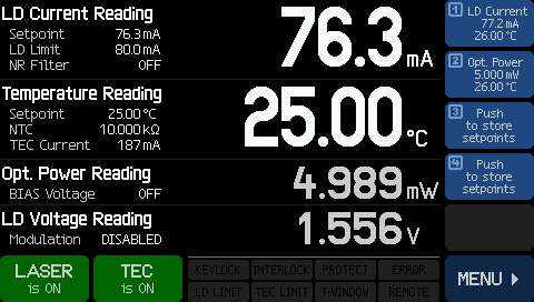 Click to Enlarge | In Constant Current Mode, the home screen emphasizes the laser diode current and temperature and displays their respective setpoints. The output power, measured by the monitor diode, is also displayed. Up to four setpoint combinations can be stored in memory. |  Click to Enlarge | In Constant Power Mode, the home screen emphasizes the laser output power and diode temperature. The laser diode current is also displayed. |
| Setpoint Entry | Menu Screen | ||
 Click to Enlarge | Each setpoint is easily modified. Simply tap the value to be changed, and buttons appear on the right that allow the value to be set. The current value of the parameter remains displayed while tweaking. | Click to Enlarge | The CLD1010LP and CLD1011LP are configured through an intuitive two-level menu structure. All settings related to the laser and the thermoelectric cooler are made here, and several other system settings are provided. |
TO Can Diodes Compatible with the CLD1010LP
The CLD1010LP Laser Diode Driver and Temperature Controller is compatible with pigtailed TO Can laser diodes that have an A, D, E, or G pin code. Please use the pin diagrams in Figure 4.1 to classify your specific laser diode package and verify CLD1010LP compatibility. Details on the correct orientation for installing each pin code can be found in the manual. Please note that only laser diodes with pin codes that include a photodiode can be operated in constant power mode.
Figure 4.1 Compatible Pin Configurations for the CLD1010LP Controller
| Pin | Pin Code A | Pin Code D | Pin Code E | Pin Code G |
|---|---|---|---|---|
| 1 | LD Cathode | LD Ground | No Connection | LD Cathode |
| 2 | Ground | PD Anode | LD Ground | Ground |
| 3 | PD Anode | LD Cathode | LD Cathode | LD Anode |
| 4 | N/A | PD Cathode | N/A | N/A |
TO Can Diodes Compatible with the CLD1011LP
The CLD1011LP Laser Diode Driver and Temperature Controller is compatible with pigtailed TO Can laser diodes that have a B, C, or H pin code. Please use the pin diagrams in Figure 4.2 to classify your specific laser diode package and verify CLD1011LP compatibility. Details on the correct orientation for installing each pin code can be found in the manual. Please note that only laser diodes with pin codes that include a photodiode can be operated in constant power mode.

Figure 4.2 Compatible Pin Configurations for the CLD1011LP Controller
| Pin | Pin Code B | Pin Code C | Pin Code H |
|---|---|---|---|
| 1 | LD Anode | LD Anode | LD Anode |
| 2 | Ground | Ground | Ground |
| 3 | PD Anode | PD Cathode | No Connection |
Software for Laser Diode Controllers
The download button below links to VISA VXI pnp™, MS Visual Studio™, MS Visual Studio.net™, LabVIEW™, and LabWindows/CVI™ drivers, firmware, utilities, and support documentation for Thorlabs' ITC4000 Series laser controllers, LDC4000 Series laser controllers, CLD1000 Series compact laser diode controllers, and TED4000 Series TEC controllers.
The software download page also offers programming reference notes for interfacing with compatible controllers using SCPI, LabVIEW, Visual C++, Visual C#, and Visual Basic. Please see the Programming Reference tab on the software download page for more information and download links.
Driver Software
Version 3.1.0 (April 11, 2014)
Programming Reference
Version 3.3 (April 8, 2015) - SCPI Commands
Version 1.0 (June 16, 2015) - LabVIEW, Visual C++, Visual C#, Visual Basic
The software packages support LabVIEW 8.5 and higher. If you are using an earlier version of LabVIEW, please contact Technical Support for assistance.
PID Basics
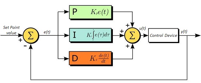
The PID circuit is often utilized as a control loop feedback controller and is commonly used for many forms of servo circuits. The letters making up the acronym PID correspond to Proportional (P), Integral (I), and Derivative (D), which represents the three control settings of a PID circuit. The purpose of any servo circuit is to hold the system at a predetermined value (set point) for long periods of time. The PID circuit actively controls the system so as to hold it at the set point by generating an error signal that is essentially the difference between the set point and the current value. The three controls relate to the time-dependent error signal. At its simplest, this can be thought of as follows: Proportional is dependent upon the present error, Integral is dependent upon the accumulation of past error, and Derivative is the prediction of future error. The results of each of the controls are then fed into a weighted sum, which then adjusts the output of the circuit, u(t). This output is fed into a control device, its value is fed back into the circuit, and the process is allowed to actively stabilize the circuit’s output to reach and hold at the set point value. The block diagram below illustrates the action of a PID circuit. One or more of the controls can be utilized in any servo circuit depending on system demand and requirement (i.e., P, I, PI, PD, or PID).
Through proper setting of the controls in a PID circuit, relatively quick response with minimal overshoot (passing the set point value) and ringing (oscillation about the set point value) can be achieved. Let’s take as an example a temperature servo, such as that for temperature stabilization of a laser diode. The PID circuit will ultimately servo the current to a Thermoelectric Cooler (TEC) (often times through control of the gate voltage on an FET). Under this example, the current is referred to as the Manipulated Variable (MV). A thermistor is used to monitor the temperature of the laser diode, and the voltage over the thermistor is used as the Process Variable (PV). The Set Point (SP) voltage is set to correspond to the desired temperature. The error signal, e(t), is then the difference between the SP and PV. A PID controller will generate the error signal and then change the MV to reach the desired result. For example, if e(t) states that the laser diode is too hot, the circuit will allow more current to flow through the TEC (proportional control). Since proportional control is proportional to e(t), it may not cool the laser diode quickly enough. In that event, the circuit will further increase the amount of current through the TEC (integral control) by looking at the previous errors and adjusting the output to reach the desired value. As the SP is reached (e(t) approaches zero), the circuit will decrease the current through the TEC in anticipation of reaching the SP (derivative control).
Please note that a PID circuit will not guarantee optimal control. Improper setting of the PID controls can cause the circuit to oscillate significantly and lead to instability in control. It is up to the user to properly adjust the PID gains to ensure proper performance.
PID Theory
The output of the PID control circuit, u(t), is given as
where
Kp= Proportional Gain
Ki = Integral Gain
Kd = Derivative Gain
e(t) = SP - PV(t)
From here we can define the control units through their mathematical definition and discuss each in a little more detail. Proportional control is proportional to the error signal; as such, it is a direct response to the error signal generated by the circuit:
Larger proportional gain results in larger changes in response to the error, and thus affects the speed at which the controller can respond to changes in the system. While a high proportional gain can cause a circuit to respond swiftly, too high a value can cause oscillations about the SP value. Too low a value and the circuit cannot efficiently respond to changes in the system.
Integral control goes a step further than proportional gain, as it is proportional to not just the magnitude of the error signal but also the duration of the error.
Integral control is highly effective at increasing the response time of a circuit along with eliminating the steady-state error associated with purely proportional control. In essence integral control sums over the previous error, which was not corrected, and then multiplies that error by Ki to produce the integral response. Thus, for even small sustained error, a large aggregated integral response can be realized. However, due to the fast response of integral control, high gain values can cause significant overshoot of the SP value and lead to oscillation and instability. Too low, and the circuit will be significantly slower in responding to changes in the system.
Derivative control attempts to reduce the overshoot and ringing potential from proportional and integral control. It determines how quickly the circuit is changing over time (by looking at the derivative of the error signal) and multiplies it by Kd to produce the derivative response.
Unlike proportional and integral control, derivative control will slow the response of the circuit. In doing so, it is able to partially compensate for the overshoot as well as damp out any oscillations caused by integral and proportional control. High gain values cause the circuit to respond very slowly and can leave one susceptible to noise and high frequency oscillation (as the circuit becomes too slow to respond quickly). Too low and the circuit is prone to overshooting the SP value. However, in some cases overshooting the SP value by any significant amount must be avoided and thus a higher derivative gain (along with lower proportional gain) can be used. The chart below explains the effects of increasing the gain of any one of the parameters independently.
| Parameter Increased | Rise Time | Overshoot | Settling Time | Steady-State Error | Stability |
|---|---|---|---|---|---|
| Kp | Decrease | Increase | Small Change | Decrease | Degrade |
| Ki | Decrease | Increase | Increase | Decrease Significantly | Degrade |
| Kd | Minor Decrease | Minor Decrease | Minor Decrease | No Effect | Improve (for small Kd) |
Tuning
In general the gains of P, I, and D will need to be adjusted by the user in order to best servo the system. While there is not a static set of rules for what the values should be for any specific system, following the general procedures should help in tuning a circuit to match one’s system and environment. A PID circuit will typically overshoot the SP value slightly and then quickly damp out to reach the SP value.
Manual tuning of the gain settings is the simplest method for setting the PID controls. However, this procedure is done actively (the PID controller turned on and properly attached to the system) and requires some amount of experience to fully integrate. To tune your PID controller manually, first the integral and derivative gains are set to zero. Increase the proportional gain until you observe oscillation in the output. Your proportional gain should then be set to roughly half this value. After the proportional gain is set, increase the integral gain until any offset is corrected for on a time scale appropriate for your system. If you increase this gain too much, you will observe significant overshoot of the SP value and instability in the circuit. Once the integral gain is set, the derivative gain can then be increased. Derivative gain will reduce overshoot and damp the system quickly to the SP value. If you increase the derivative gain too much, you will see large overshoot (due to the circuit being too slow to respond). By playing with the gain settings, you can maximize the performance of your PID circuit, resulting in a circuit that quickly responds to changes in the system and effectively damps out oscillation about the SP value.
| Control Type | Kp | Ki | Kd |
|---|---|---|---|
| P | 0.50 Ku | - | - |
| PI | 0.45 Ku | 1.2 Kp/Pu | - |
| PID | 0.60 Ku | 2 Kp/Pu | KpPu/8 |
While manual tuning can be very effective at setting a PID circuit for your specific system, it does require some amount of experience and understanding of PID circuits and response. The Ziegler-Nichols method for PID tuning offers a bit more structured guide to setting PID values. Again, you’ll want to set the integral and derivative gain to zero. Increase the proportional gain until the circuit starts to oscillate. We will call this gain level Ku. The oscillation will have a period of Pu. Gains for various control circuits are then given to the right in the chart.
Note that when using the Ziegler-Nichols tuning method with some devices like the DSC1 digital servo controller, the integral and derivative terms must be normalized by the sample rate. To do this, the integral term determined from the table should be divided by the sample rate in Hertz and the derivative term should be multiplied by the sample rate in Hertz.
Video Insight: Setting Up a TO Can Laser Diode
Installing a TO can laser diode in a mount and setting it up to run under temperature and current control presents many opportunities to make a mistake that could damage or destroy the laser. This step-by-step guide includes tips for keeping humans and laser diodes safe from harm.
If you would like more information about tips, tricks, and other methods we often use in the lab, we recommend our other Video Insights. In addition, our webinars provide practical and theoretical introductions to our different products.
| Posted Comments: | |
user
(posted 2025-06-17 07:46:13.337) My CLD1010LP screen is broken, and so it is not allowing me to turn on the laser when it reaches the specified temperature. Is there a way to control the screen settings on a separate device? jjadvani
(posted 2025-06-17 04:33:24.0) Dear User, Thank you for providing feedback. We recommend sending the devices back for repair first. If that is not feasible, you can communicate with the device using the software available on our website. Page 31 of the manual contains a full discussion of how to control the device using a USB connection. user
(posted 2025-05-29 21:16:29.77) I used pigtailed laser diode (LP405C1) with CLD1010LP and they worked well but i changed laser diode to a different wavelength for a while and then changed it back to the LP405C1. Then after connecting, I've got this message when i turn on the laser after TEC on. 'Laser output switched off. Voltage protection was tripped.' And also I think I've seen a sentence about 'open circuit' for a while. Does it came from connection problem of laser diode caused by bending terminals? How can i fix it? jjadvani
(posted 2025-05-30 06:15:18.0) Dear User, Thank you for providing feedback. The error you are seeing can occur for a variety of reasons. For example, if the laser chip is damaged, the forward voltage becomes too large for the drive current, or if the laser diode is not mounted in the socket properly, the forward voltage becomes too high, and the laser output is switched off for protection. I'll contact you directly to provide more details. jiatong zhang
(posted 2025-03-28 16:05:07.383) Can I manipulate the Current at a period of 10MHz? jjadvani
(posted 2025-03-28 06:21:51.0) Dear Jiatong, Thank you for contacting Thorlabs. You can use the SMA connector on the CLD1010LP or CLD1011LP for RF modulation input to control the current at a 10 MHz rate. I will contact you directly to provide further information. user
(posted 2024-03-18 10:47:14.093) Dear Sir or Madame,
I would like use CLD1011LP with LPS-660-FC as reliable pulsed light source to induce resonant effect of microsystem. However, I don't know exactly how to set the setup to generate pulses of light ranging repetition rate from 10kHz to 250 kHz. I assume, despite the two above elements I need the another external fiber to guide the light through to the setup. Do I need another instrument to obtain pulse generation. What type for instance?. What means external modulation in the manual?
Thank You in advance for Your help. dpossin
(posted 2024-03-18 09:22:35.0) Dear Anna,
Thank you for your inquiry. I´ll reach out to you in order to provide detailed information. user
(posted 2023-05-31 23:41:25.39) Can this device drive a 300mW laser diode (14 pin butterfly).
Does it need special thermal conducting mounting to manage the heat dissipation?
Thank you hchow
(posted 2023-06-05 06:12:03.0) Dear User, thank you for your feedback. I believe the laser diode driver you are looking for is the CLD1015 instead. The CLD1015 has a current range of between 1 mA to 1.5 A with a compliance voltage of 4 V. Whether or not this device can drive your 300 mW laser diode, depends on its specified drive current. The butterfly mount on the CLD1015 can accommodate 14 pin butterfly laser diodes. Paweł Aleszkiewicz
(posted 2021-03-26 08:40:46.117) Dear Sears,
Can you give me comparison of current drift (p-p) per 1-5h, for LDC202C, KLD101 and CLD1010LP? MKiess
(posted 2021-04-07 05:35:25.0) Dear Pawel, thank you very much for your inquiry. You can find the current drift over 24h in the specification sheets of the individual laser diode drivers. These are available under the documents of the respective product on our website. I have contacted you directly to provide you with these documents as well. Ricardo Adão
(posted 2021-02-25 11:59:57.323) I have the following two lasers (datasheets links below), and I would like to know if the compact Laser Diode Driver CLD1010LP is compatible/suitable to control them.
http://www.roithner-laser.com/datasheets/ld_fiber/spl830-5-4-pd.pdf
http://www.roithner-laser.com/datasheets/ld_fiber/spl635-5-4-pd.pdf
Many thanks! dpossin
(posted 2021-03-01 11:04:12.0) Dear Ricardo,
Thank you for your feedback. With respect to the pin diagram, the two suggested lasers are compatible to the CLD1010LP lasercontroller. Please note that the maximum reverse bias the controller provides is 6V which is less than the indicated PD reverse bias voltage of 30V one can apply to the PD input of your lasers.
I am reaching out to you in order to further discuss this. user
(posted 2019-03-27 09:39:52.957) Our lab has bought the CLD1010LP two years ago. Recently, the fiber was broken by mistake and we are wondering how to fix this problem. should we buy some module to replace the fiber or send the CLD1010LP back to thorlabs to fix it? Thanks! YLohia
(posted 2019-04-08 11:05:03.0) Hello, thank you for contacting Thorlabs. What fiber are you referring to? Is it the fiber attached to the laser diode pigtail? If so, that is a separate issue and does not affect the CLD1010LP. If the laser diode was purchased from us, we are able to reterminate the fiber (assuming the break occurred 10cm or more away from the boot). We have reached out to you directly to discuss this. user
(posted 2014-12-08 18:22:08.927) Is it a resistive or capacitive display? shallwig
(posted 2014-12-09 02:53:49.0) This is a response from Stefan at Thorlabs. Thank you very much for your inquiry. These controllers have a resistive display built in. |
Laser Diode Controller Selection Guide
Tables 137A and 137B are designed to give a quick overview of the key specifications for our laser diode controllers and dual diode/temperature controllers. For more details and specifications, or to order a specific item, click on the appropriate item number below.
| Table 137A Current Controllers | ||||||
|---|---|---|---|---|---|---|
| Item # | Drive Current | Compliance Voltage | Constant Current | Constant Power | Modulation | Package |
| LDC200CV | 20 mA | 6 V | External | Benchtop | ||
| VLDC002 | 25 mA | 5 V | - | Int/Ext | OEM | |
| LDC201CU | 100 mA | 5 V | External | Benchtop | ||
| LD2000R | 100 mA | 3.5 V | - | External | OEM | |
| EK2000 | 100 mA | 3.5 V | - | External | OEM | |
| LDC202C | 200 mA | 10 V | External | Benchtop | ||
| KLD101 | 230 mA | ≤10 V | External | K-Cube® | ||
| IP250-BV | 250 mA | 8 Va | External | OEM | ||
| LD1100 | 250 mA | 6.5 Va | - | -- | OEM | |
| LD1101 | 250 mA | 6.5 Va | - | -- | OEM | |
| EK1101 | 250 mA | 6.5 Va | - | -- | OEM | |
| EK1102 | 250 mA | 6.5 Va | - | -- | OEM | |
| LD1255R | 250 mA | 3.3 V | - | External | OEM | |
| LDC205C | 500 mA | 10 V | External | Benchtop | ||
| IP500 | 500 mA | 3 V | External | OEM | ||
| LDC210C | 1 A | 10 V | External | Benchtop | ||
| LDC220C | 2 A | 4 V | External | Benchtop | ||
| LD3000R | 2.5 A | -- | - | External | OEM | |
| LDC240C | 4 A | 5 V | External | Benchtop | ||
| LDC4005 | 5 A | 12 V | Int/Ext | Benchtop | ||
| LDC4020 | 20 A | 11 V | Int/Ext | Benchtop | ||
| Table 137B Dual Temperature and Current Controllers | |||||||
|---|---|---|---|---|---|---|---|
| Item # | Drive Current | Compliance Voltage | TEC Power (Max) | Constant Current | Constant Power | Modulation | Package |
| VITC002 | 25 mA | 5 V | >2 W | - | Int/Ext | OEM | |
| ITC102 | 200 mA | >4 V | 12 W | Ext | OEM | ||
| ITC110 | 1 A | >4 V | 12 W | Ext | OEM | ||
| ITC4001 | 1 A | 11 V | >96 W | Int/Ext | Benchtop | ||
| CLD1010LPa | 1.0 A | >8 V | >14.1 W | Ext | Benchtop | ||
| CLD1011LPb | 1.0 A | >8 V | >14.1 W | Ext | Benchtop | ||
| CLD1015c | 1.5 A | >4 V | >14.1 W | Ext | Benchtop | ||
| ITC4002QCLd | 2 A | 17 V | >225 W | Int/Ext | Benchtop | ||
| ITC133 | 3 A | >4 V | 18 W | Ext | OEM | ||
| ITC4005 | 5 A | 12 V | >225 W | Int/Ext | Benchtop | ||
| ITC4005QCLd | 5 A | 20 V | >225 W | Int/Ext | Benchtop | ||
| ITC4020 | 20 A | 11 V | >225 W | Int/Ext | Benchtop | ||
We also offer a variety of OEM and rack-mounted laser diode current & temperature controllers (OEM Modules, PRO8 Current Control Rack Modules, and PRO8 Current and Temperature Control Rack Modules).

 Zoom
Zoom
- Integrated Mounts Compatible with Thorlabs' Pigtailed TO Can Laser Diodes
- CLD1010LP: Compatible with Pin Codes A, D, E, and G
- CLD1011LP: Compatible with Pin Codes B, C, and H
- Operate in Constant Current or Constant Power Mode
- Temperature-Controlled Laser Operation through Built-In TEC
Thorlabs' Compact Laser Diode and Temperature Controllers are complete driver packages designed to drive and cool TO can fiber-coupled laser diodes. These all-in-one units supply up to 1.0 A of drive current, maintain the diode temperature with 0.005 °C of stability over 24 hours, provide a high degree of output stability, and prolong the life of the diode. The controllers also contain a built-in mount for portability and mechanical stability. In additional to a full complement of safety features, such as a soft-start mode, current and temperature limits, and external interlock compatibility, the CLD1010LP and CLD1011LP controllers both include a switchable noise reduction filter and a modulation input.
The devices are controlled with built-in 4.3" diagonal, color resistive touch screens, making it easy to tune, tweak, and optimize the laser output parameters. Operating parameters are set using the intuitive menu system, and the user is never more than two taps away from the home screen. A resistive touch screen allows for the screen to be operated when using gloves or other protective equipment. In addition to the touch screen controls, a mini-USB interface on the rear of the unit enables remote control of all settings using several common programming languages, including LabVIEW and the Standard Commands for Programmable Instruments (SCPI) standard. When using the CLD1010LP or CLD1011LP to drive a laser, make sure that all of the operating parameters are set within the maximum ratings of your device. When fully assembled, these compact devices measure just 4.37" x 2.9" x 6.69" (111 mm x 73.5 mm x 169.9 mm), ideal for tightly packed setups.
| Table G2.1 CAL-CLD Recalibration Service | |
|---|---|
| Calibration Service Item # | Compatible Controllers |
| CAL-CLD | CLD1010LP CLD1011LP |
Thorlabs offers a recalibration services for our Compact Laser Diode Driver/Temperature Controllers. To ensure accurate measurements, we recommend recalibrating the devices every 24 months.
Table G2.1 lists the controllers for which the CAL-CLD recalibration service is available. Please enter the Part # and Serial # of the controller that requires recalibration prior to selecting Add to Cart.