 Products Home / Polarization Optics / Wave Plates and Variable Retarders / Zero-Order Wave Plates / Mounted Zero-Order Half-Wave Plates
Mounted Zero-Order Half-Wave Plates
- Compound Zero-Order Operation Achieved by Using Two Multi-Order Plates
- AR Coating for Design Wavelengths from 266 nm to 2020 nm
- Lower Dependence on Temperature and Wavelength than Multi-Order
Wave Plates
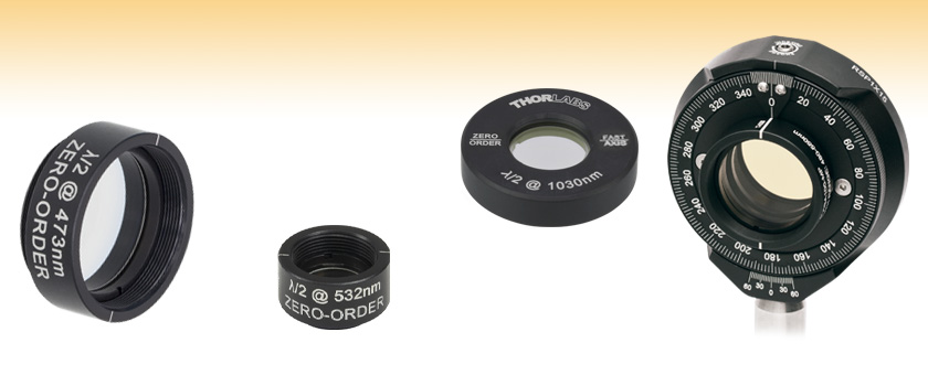
WPH10M-473
473 nm Wave Plate in
SM1-Threaded Lens Tube
WPHSM05-532
532 nm Wave Plate in
SM05-Threaded Lens Tube
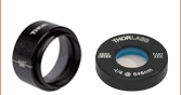
WPH05M-1030
1030 nm Wave Plate in Unthreaded Ø1" Mount
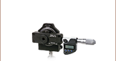
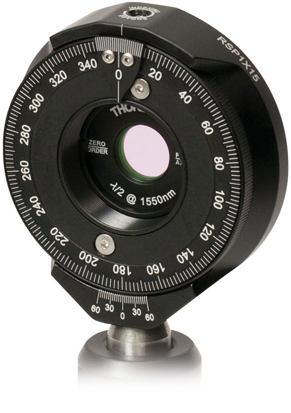
Ø1" Half-Wave Plate
Mounted in RSP1X15
Indexing Rotation Mount


Please Wait
| Common Specifications | |
|---|---|
| Material | Crystalline Quartz |
| Retardance Accuracy (Typical) | <λ/300 |
| Beam Deviation | <10 arcsec |
| Surface Quality | 20-10 Scratch-Dig |
| Reflectance @ Design Wavelength (per Surface) | <0.25% |
| Webpage Features | |
|---|---|
| Clicking this icon in the tables below opens a window that contains specifications, performance graphs, and mechanical drawings. | |
Features
- Air-Spaced Design for High Damage Threshold
- Discrete Wavelengths from 266 nm to 2020 nm
- AR Coated on All Optical Surfaces
- Ø1/2" and Ø1" Wave Plate Options
- Custom Options Available, Please Contact Tech Sales for More Information
- OEM Pricing Available Upon Request
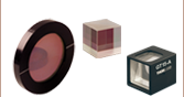
Thorlabs' Zero-Order Half-Wave Plates are built by combining two Multi-Order Crystalline Quartz Wave Plates to obtain an optical path length difference of λ/2. By aligning the fast axis of one plate with the slow axis of the other, the net result is a compound retarder whose exact retardance is the difference between each plate's individual retardance. Compound zero-order wave plates offer a lower dependence on temperature and wavelength than multi-order wave plates. Each wave plate is available as a Ø1/2" optic mounted in an SM05-threaded (0.535"-40) lens tube, a Ø1/2" optic mounted in a Ø1" unthreaded housing, or a Ø1" optic mounted in an SM1-threaded (1.035"-40) lens tube (see below for details).
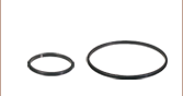
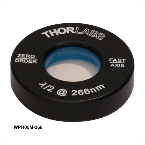
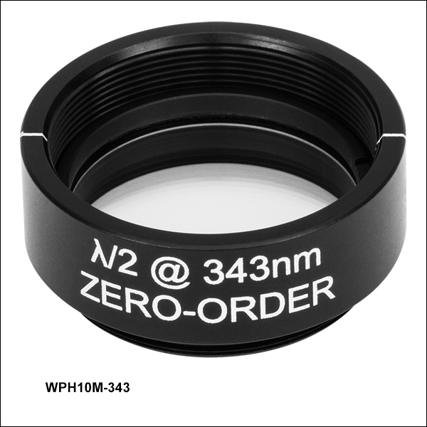
These zero-order wave plates are constructed by placing an etched stainless steel spacing ring between the two multi-order wave plates and epoxying the three pieces together (the adhesive is only applied outside of the clear aperture of the wave plate). The wave plate is then mounted in an anodized aluminum housing. The housing is engraved with a line indicating the orientation of the fast axis of the wave plate, text stating it is a zero-order half-wave plate, and the design wavelength.
 Click to Enlarge
Figure 1.1 The unmounted wave plate fast axis is parallel to the small flat.
Thorlabs can also produce custom wave plates with no AR coating, a different AR coating, or a different design wavelength than those offered below. Please contact Tech Sales with inquiries.
Thorlabs also offers offers polymer zero-order quarter-wave and half-wave plates, which can provide stable performance over wavelength shifts and large angles of incidence (AOI).
Mounting Options
Wave plates in SM05- or SM1-threaded housings can thread directly into our SM05- and SM1-threaded rotation mounts, respectively. Our 1/2" wave plates in Ø1" housings can be mounted in internally SM1-threaded components using SM1RR retaining rings.
The wave plates are easily removed from their mounts for use in custom or OEM applications; use a spanner wrench to remove the retaining ring that secures the optic in the mount (SM05 for our Ø1/2" and SM1 for our Ø1" wave plates). The unmounted wave plates have a small flat parallel to the fast axis (see Figure 1.1). For further information on using and selecting a wave plate, please see our Wave Plate Selection Guide tab or contact Tech Sales.
| Wave Plate Selection Guide | |||||||||||
|---|---|---|---|---|---|---|---|---|---|---|---|
| Quartz Zero-Order Achromatic | Polymer Zero-Order Achromatic | Superachromatic | Quartz Zero-Order Half-Wave |
Quartz Zero-Order Quarter-Wave |
Polymer Zero-Order Half-Wave |
Polymer Zero-Order Quarter-Wave |
Low-Order | Multi-Order | Dual Wavelength | Telecom | Polarization Optics |
Operating Principle of Wave Plates
Optical wave plates are constructed from birefringent materials that have a difference in refractive index between two orthogonal axes. This birefringent property introduces a velocity difference between light polarized along the fast and slow principal axes of the wave plate. The fast principal axis of the wave plate has a lower refractive index, resulting in a faster velocity for light polarized in this direction. Conversely, the slow axis has a higher refractive index, resulting in a slower velocity for light with this polarization. When light passes through a wave plate, this velocity difference leads to a phase difference between the two orthogonal polarization components. The actual phase shift depends on the properties of the material, the thickness of the wave plate, and the wavelength of the signal, and can be described as:
![]()
where n1 is the refractive index along the slow axis, n2 is the refractive index along the orthogonal fast axis, d is the thickness of the wave plate, and λ is the signal wavelength.
Using a Wave Plate
Wave plates are typically available with a retardance of λ/4 or λ/2, meaning that a phase shift of a quarter wavelength or a half a wavelength (respectively) is created.
Half-Wave
As described above, a wave plate has two principal axes: fast and slow. Each axis has a different refractive index and, therefore, a different wave velocity. When a linearly polarized beam is incident on a half-wave plate, and the polarization of this beam does not coincide with one of these axes, the output polarization will be linear and rotated with respect to the polarization of the input beam (see image at right). When applying a circularly polarized beam, a clockwise (counterclockwise) circular polarization will transform into a counterclockwise (clockwise) circular polarization.
Half-wave (λ/2) plates are typically used as polarization rotators. Mounted on a rotation mount, a λ/2 wave plate can be used as a continuously adjustable polarization rotator, as shown below. Additionally, when used in conjunction with a Polarizing Beamsplitter a λ/2 wave plate can be used as a variable ratio beamsplitter.
The angle between the output polarization and the input polarization will be twice the angle between the input polarization and the wave plate’s axis (see diagram to the lower right). When the polarization of the input beam is directed along one of the axes of the wave plate, the polarization direction will remain unchanged.
Quarter-Wave
A quarter-wave plate is designed such that the phase shift created between the fast and slow axes is a quarter wavelength (λ/4). If the input beam is linearly polarized with the polarization plane aligned at 45° to the wave plate's fast or slow axis, then the output beam will be circularly polarized (see image at right). If the linearly polarized beam is aligned at an angle other than 45°, then the output will be elliptically polarized. Conversely, the application of a circularly polarized beam to a λ/4 wave plate results in a linearly polarized output beam. Quarter wave plates are used in Optical Isolators, optical pumps, and EO Modulators.
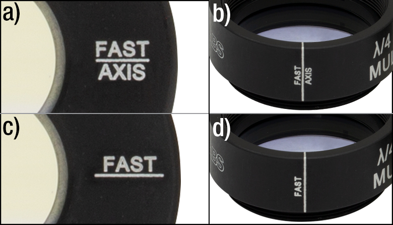
Click to Enlarge
Figure 1: Top Images (a,b): Engraving Reflects Updated Assembly Process as of October 2018; Bottom Images (c,d): Past Engraving
Fast and Slow Axis Identification
In October 2018, Thorlabs updated its wave plate assembly process and associated product engravings to be consistent with the IEEE/SPIE convention (see the Polarization Handedness Tutorial) for determining the fast and slow axes. By this convention, the current revisions of wave plates have the fast axis denoted by the “FAST AXIS” engraving visible in Figure 1 to the right. Although the location of the axes and the retardation value for each wave plate is easily determined, differentiating between the fast and slow axes is far more involved.
For most applications, the knowledge of whether an axis is fast or slow is not nearly as important as the retardation value. However, the fast/slow difference determines the left/right-hand circular polarization of light output from a quarter-wave plate, which can be important in applications such as atomic and solid state physics spectroscopy. To ensure the accuracy of our labeling moving forward, we have incorporated several redundant testing setups into our production processes, as described below.
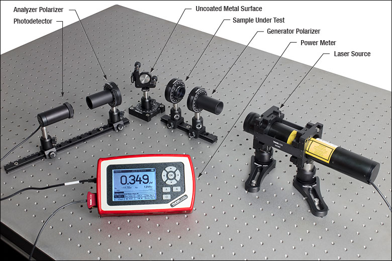
Test Setup 1: Reflection Off Uncoated Metal with n > 1
This test setup is based on the method of Petre Logofatu1, which is also summarized well by Galgano and Henriques2. In this method, a light source passes through a generator, which is a linear polarizer oriented at 45° to the horizontal. Then, the light passes through the wave plate sample under test (SUT), is reflected off an uncoated metal surface (any metal with n > 1 will suffice), and passes through an analyzer (a second linear polarizer oriented at 90° to the generator). The light is then measured by a power sensor.
Our setup, shown in Figure 2 to the right, used a HeNe laser as the light source, two GTH10M-A Glan-Taylor polarizers as the generator and analyzer, a custom uncoated stainless steel reflective surface, an S120C power sensor, and a PM100D power meter console. A full parts list, except the custom metal surface and SUT, is provided below Figure 2.
As described by Logofatu, the power reflection coefficient, R in the equation below, can be derived from the Fresnel equations, showing that there will be a large difference in reflection off the metal depending on whether the fast or the slow axis of the SUT is horizontal.
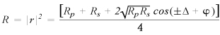
Here, Rp and Rs represent the p-polarized and s-polarized components of R, Δ is the retardance of the SUT, and φ is the phase difference between the p and s reflection coefficients of the metallic surface. From this, we can determine which axis we would expect a higher reflection value when horizontal, and compare expected values to experimental values. Using a large angle of incidence allows for a large separation between s and p coefficients. This correlates with high versus low measured reflection, enabling easy determination of fast versus slow axis. As in both papers, the test was performed at a variety of angles. The results were then fitted to a theoretical curve.
The equation for R shown above differs from that in the Logofatu reference, in which we identified an error; our Reflection Coefficient Derivation PDF shows our own derivation of the Logofatu result.
Click to Enlarge
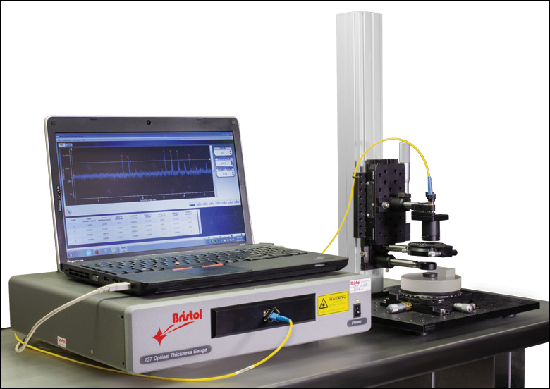
Figure 3: Low Coherence Interferometry Wave Plate Testing Setup
Test Setup 2: Low Coherence Interferometry
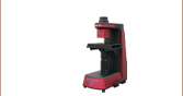
This test setup uses low coherence interferometry to measure the optical path length (OPL) of the SUT as it is rotated, where the longest OPL corresponds with the slow axis, and the shortest OPL corresponds with the fast axis. This method is additionally verified by modifying the reference arm of the interferometer, adding a reference window and specular back surface to allow for calculation of the group index (ngSUT) along and normal to the crystal axis. These values can then be compared to known values, assuring the reliability of this test.
Our setup, shown in Figure 3 to the right, used a modified Bristol 157 Series Optical Gauge. As can be seen in Figure 4 below, the majority of the low coherence interferometer is contained within the chassis of the optical gaugea. The measurement arm is then modified with Thorlabs components, such that the fiber output can be aligned with a low NA objective, passed through a LPNIR100 linear polarizer and partially reflected off a WG11010 reference window, all mounted on a 34 mm rail. The light then reflects off the SUT and a custom specular back surface to send the interferometric signal back to the optical gauge.
The additional reference surfaces and resulting physical thickness are used to double check the validity of the results. This is done with a quick calculation to determine the group index of both the fast and slow axes. Figure 5 shows a qualitative representation of the output produced by this setup. Peaks 1 and 2 are created by the reference window, Peaks 3 and 4 by the SUT wave plate, while Peak 5 is generated by the reference surface. Thickness data from peak to peak are calculated by the software and output into a table. By first taking the distance from Peak 2 to Peak 5 before the wave plate is inserted, the total physical thickness, Tair0, is obtainedb. When inserting the wave plate, we can then take the distance from Peak 2 to 3, Tair1, and Peak 4 to 5, Tair2. Using this information we can easily calculate the thickness of the wave plate, TSUT by subtracting Tair1 and Tair2 from Tair0. Measuring the distance from Peak 3 to Peak 4 would give us OPLSUT. Dividing OPLSUT by TSUT produces the group index of the SUT, ngSUT. Comparing this group index to that provided in literature for quartz3 or MgF24 both along and normal to the crystal axis, we are in good agreement.
Click to Enlarge
Figure 4: Example Low Coherence Interferometry Diagram;
Numbered reflections in the measurement arm correspond with peak numbers in Figure 5.
Click to Enlarge
Figure 5: Representation of Output from Optical Gauge
| Table 3.1 Damage Threshold Specifications | |
|---|---|
| Coating Designation (Item # Suffix) |
Damage Threshold |
| -266 | 10 J/cm2 (266 nm, 10 ns, 10 Hz, Ø0.228 mm) |
| -355 | 10 J/cm2 (355 nm, 10 ns, 10 Hz, Ø0.179 mm) |
| -532 | 10 J/cm2 (532 nm, 10 ns, 10 Hz, Ø0.242 mm) |
| -808 | 0.448 J/cm2 (797 nm, 180 fs, 1 kHz, Ø0.178 mm) 10 J/cm2 (810 nm, 10 ns, 10 Hz, Ø0.055 mm) |
| -1064 | 10 J/cm2 (1064 nm, 10 ns, 10 Hz, Ø0.433 mm) |
| -1550 | 20 J/cm2 (1542 nm, 10 ns, 10 Hz, Ø0.105 mm) |
| -2020 | 10 J/cm2 (2050 nm, 10 ns, 10 Hz, Ø0.186 mm) |
Damage Threshold Data for Thorlabs' Wave Plates
The specifications in Table 3.1 are measured data for Thorlabs' wave plates. Damage threshold specifications are constant for a given center wavelength, regardless of the size of the wave-plate.
Laser Induced Damage Threshold Tutorial
The following is a general overview of how laser induced damage thresholds are measured and how the values may be utilized in determining the appropriateness of an optic for a given application. When choosing optics, it is important to understand the Laser Induced Damage Threshold (LIDT) of the optics being used. The LIDT for an optic greatly depends on the type of laser you are using. Continuous wave (CW) lasers typically cause damage from thermal effects (absorption either in the coating or in the substrate). Pulsed lasers, on the other hand, often strip electrons from the lattice structure of an optic before causing thermal damage. Note that the guideline presented here assumes room temperature operation and optics in new condition (i.e., within scratch-dig spec, surface free of contamination, etc.). Because dust or other particles on the surface of an optic can cause damage at lower thresholds, we recommend keeping surfaces clean and free of debris. For more information on cleaning optics, please see our Optics Cleaning tutorial.
Testing Method
Thorlabs' LIDT testing is done in compliance with ISO/DIS 11254 and ISO 21254 specifications.
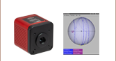
First, a low-power/energy beam is directed to the optic under test. The optic is exposed in 10 locations to this laser beam for 30 seconds (CW) or for a number of pulses (pulse repetition frequency specified). After exposure, the optic is examined by a microscope (~100X magnification) for any visible damage. The number of locations that are damaged at a particular power/energy level is recorded. Next, the power/energy is either increased or decreased and the optic is exposed at 10 new locations. This process is repeated until damage is observed. The damage threshold is then assigned to be the highest power/energy that the optic can withstand without causing damage. A histogram such as that below represents the testing of one BB1-E02 mirror.
The photograph above is a protected aluminum-coated mirror after LIDT testing. In this particular test, it handled 0.43 J/cm2 (1064 nm, 10 ns pulse, 10 Hz, Ø1.000 mm) before damage.
| Example Test Data | |||
|---|---|---|---|
| Fluence | # of Tested Locations | Locations with Damage | Locations Without Damage |
| 1.50 J/cm2 | 10 | 0 | 10 |
| 1.75 J/cm2 | 10 | 0 | 10 |
| 2.00 J/cm2 | 10 | 0 | 10 |
| 2.25 J/cm2 | 10 | 1 | 9 |
| 3.00 J/cm2 | 10 | 1 | 9 |
| 5.00 J/cm2 | 10 | 9 | 1 |
According to the test, the damage threshold of the mirror was 2.00 J/cm2 (532 nm, 10 ns pulse, 10 Hz, Ø0.803 mm). Please keep in mind that these tests are performed on clean optics, as dirt and contamination can significantly lower the damage threshold of a component. While the test results are only representative of one coating run, Thorlabs specifies damage threshold values that account for coating variances.
Continuous Wave and Long-Pulse Lasers
When an optic is damaged by a continuous wave (CW) laser, it is usually due to the melting of the surface as a result of absorbing the laser's energy or damage to the optical coating (antireflection) [1]. Pulsed lasers with pulse lengths longer than 1 µs can be treated as CW lasers for LIDT discussions.
When pulse lengths are between 1 ns and 1 µs, laser-induced damage can occur either because of absorption or a dielectric breakdown (therefore, a user must check both CW and pulsed LIDT). Absorption is either due to an intrinsic property of the optic or due to surface irregularities; thus LIDT values are only valid for optics meeting or exceeding the surface quality specifications given by a manufacturer. While many optics can handle high power CW lasers, cemented (e.g., achromatic doublets) or highly absorptive (e.g., ND filters) optics tend to have lower CW damage thresholds. These lower thresholds are due to absorption or scattering in the cement or metal coating.
LIDT in linear power density vs. pulse length and spot size. For long pulses to CW, linear power density becomes a constant with spot size. This graph was obtained from [1].
Pulsed lasers with high pulse repetition frequencies (PRF) may behave similarly to CW beams. Unfortunately, this is highly dependent on factors such as absorption and thermal diffusivity, so there is no reliable method for determining when a high PRF laser will damage an optic due to thermal effects. For beams with a high PRF both the average and peak powers must be compared to the equivalent CW power. Additionally, for highly transparent materials, there is little to no drop in the LIDT with increasing PRF.
In order to use the specified CW damage threshold of an optic, it is necessary to know the following:
- Wavelength of your laser
- Beam diameter of your beam (1/e2)
- Approximate intensity profile of your beam (e.g., Gaussian)
- Linear power density of your beam (total power divided by 1/e2 beam diameter)
Thorlabs expresses LIDT for CW lasers as a linear power density measured in W/cm. In this regime, the LIDT given as a linear power density can be applied to any beam diameter; one does not need to compute an adjusted LIDT to adjust for changes in spot size, as demonstrated by the graph to the right. Average linear power density can be calculated using the equation below.

The calculation above assumes a uniform beam intensity profile. You must now consider hotspots in the beam or other non-uniform intensity profiles and roughly calculate a maximum power density. For reference, a Gaussian beam typically has a maximum power density that is twice that of the uniform beam (see lower right).
Now compare the maximum power density to that which is specified as the LIDT for the optic. If the optic was tested at a wavelength other than your operating wavelength, the damage threshold must be scaled appropriately. A good rule of thumb is that the damage threshold has a linear relationship with wavelength such that as you move to shorter wavelengths, the damage threshold decreases (i.e., a LIDT of 10 W/cm at 1310 nm scales to 5 W/cm at 655 nm):

While this rule of thumb provides a general trend, it is not a quantitative analysis of LIDT vs wavelength. In CW applications, for instance, damage scales more strongly with absorption in the coating and substrate, which does not necessarily scale well with wavelength. While the above procedure provides a good rule of thumb for LIDT values, please contact Tech Support if your wavelength is different from the specified LIDT wavelength. If your power density is less than the adjusted LIDT of the optic, then the optic should work for your application.
Please note that we have a buffer built in between the specified damage thresholds online and the tests which we have done, which accommodates variation between batches. Upon request, we can provide individual test information and a testing certificate. The damage analysis will be carried out on a similar optic (customer's optic will not be damaged). Testing may result in additional costs or lead times. Contact Tech Support for more information.
Pulsed Lasers
As previously stated, pulsed lasers typically induce a different type of damage to the optic than CW lasers. Pulsed lasers often do not heat the optic enough to damage it; instead, pulsed lasers produce strong electric fields capable of inducing dielectric breakdown in the material. Unfortunately, it can be very difficult to compare the LIDT specification of an optic to your laser. There are multiple regimes in which a pulsed laser can damage an optic and this is based on the laser's pulse length. The highlighted columns in the table below outline the relevant pulse lengths for our specified LIDT values.
Pulses shorter than 10-9 s cannot be compared to our specified LIDT values with much reliability. In this ultra-short-pulse regime various mechanics, such as multiphoton-avalanche ionization, take over as the predominate damage mechanism [2]. In contrast, pulses between 10-7 s and 10-4 s may cause damage to an optic either because of dielectric breakdown or thermal effects. This means that both CW and pulsed damage thresholds must be compared to the laser beam to determine whether the optic is suitable for your application.
| Pulse Duration | t < 10-9 s | 10-9 < t < 10-7 s | 10-7 < t < 10-4 s | t > 10-4 s |
|---|---|---|---|---|
| Damage Mechanism | Avalanche Ionization | Dielectric Breakdown | Dielectric Breakdown or Thermal | Thermal |
| Relevant Damage Specification | No Comparison (See Above) | Pulsed | Pulsed and CW | CW |
When comparing an LIDT specified for a pulsed laser to your laser, it is essential to know the following:
LIDT in energy density vs. pulse length and spot size. For short pulses, energy density becomes a constant with spot size. This graph was obtained from [1].
- Wavelength of your laser
- Energy density of your beam (total energy divided by 1/e2 area)
- Pulse length of your laser
- Pulse repetition frequency (prf) of your laser
- Beam diameter of your laser (1/e2 )
- Approximate intensity profile of your beam (e.g., Gaussian)
The energy density of your beam should be calculated in terms of J/cm2. The graph to the right shows why expressing the LIDT as an energy density provides the best metric for short pulse sources. In this regime, the LIDT given as an energy density can be applied to any beam diameter; one does not need to compute an adjusted LIDT to adjust for changes in spot size. This calculation assumes a uniform beam intensity profile. You must now adjust this energy density to account for hotspots or other nonuniform intensity profiles and roughly calculate a maximum energy density. For reference a Gaussian beam typically has a maximum energy density that is twice that of the 1/e2 beam.
Now compare the maximum energy density to that which is specified as the LIDT for the optic. If the optic was tested at a wavelength other than your operating wavelength, the damage threshold must be scaled appropriately [3]. A good rule of thumb is that the damage threshold has an inverse square root relationship with wavelength such that as you move to shorter wavelengths, the damage threshold decreases (i.e., a LIDT of 1 J/cm2 at 1064 nm scales to 0.7 J/cm2 at 532 nm):

You now have a wavelength-adjusted energy density, which you will use in the following step.
Beam diameter is also important to know when comparing damage thresholds. While the LIDT, when expressed in units of J/cm², scales independently of spot size; large beam sizes are more likely to illuminate a larger number of defects which can lead to greater variances in the LIDT [4]. For data presented here, a <1 mm beam size was used to measure the LIDT. For beams sizes greater than 5 mm, the LIDT (J/cm2) will not scale independently of beam diameter due to the larger size beam exposing more defects.
The pulse length must now be compensated for. The longer the pulse duration, the more energy the optic can handle. For pulse widths between 1 - 100 ns, an approximation is as follows:

Use this formula to calculate the Adjusted LIDT for an optic based on your pulse length. If your maximum energy density is less than this adjusted LIDT maximum energy density, then the optic should be suitable for your application. Keep in mind that this calculation is only used for pulses between 10-9 s and 10-7 s. For pulses between 10-7 s and 10-4 s, the CW LIDT must also be checked before deeming the optic appropriate for your application.
Please note that we have a buffer built in between the specified damage thresholds online and the tests which we have done, which accommodates variation between batches. Upon request, we can provide individual test information and a testing certificate. Contact Tech Support for more information.
[1] R. M. Wood, Optics and Laser Tech. 29, 517 (1998).
[2] Roger M. Wood, Laser-Induced Damage of Optical Materials (Institute of Physics Publishing, Philadelphia, PA, 2003).
[3] C. W. Carr et al., Phys. Rev. Lett. 91, 127402 (2003).
[4] N. Bloembergen, Appl. Opt. 12, 661 (1973).

In order to illustrate the process of determining whether a given laser system will damage an optic, a number of example calculations of laser induced damage threshold are given below. For assistance with performing similar calculations, we provide a spreadsheet calculator that can be downloaded by clicking the LIDT Calculator button. To use the calculator, enter the specified LIDT value of the optic under consideration and the relevant parameters of your laser system in the green boxes. The spreadsheet will then calculate a linear power density for CW and pulsed systems, as well as an energy density value for pulsed systems. These values are used to calculate adjusted, scaled LIDT values for the optics based on accepted scaling laws. This calculator assumes a Gaussian beam profile, so a correction factor must be introduced for other beam shapes (uniform, etc.). The LIDT scaling laws are determined from empirical relationships; their accuracy is not guaranteed. Remember that absorption by optics or coatings can significantly reduce LIDT in some spectral regions. These LIDT values are not valid for ultrashort pulses less than one nanosecond in duration.
Figure 71A A Gaussian beam profile has about twice the maximum intensity of a uniform beam profile.
CW Laser Example
Suppose that a CW laser system at 1319 nm produces a 0.5 W Gaussian beam that has a 1/e2 diameter of 10 mm. A naive calculation of the average linear power density of this beam would yield a value of 0.5 W/cm, given by the total power divided by the beam diameter:
However, the maximum power density of a Gaussian beam is about twice the maximum power density of a uniform beam, as shown in Figure 71A. Therefore, a more accurate determination of the maximum linear power density of the system is 1 W/cm.
An AC127-030-C achromatic doublet lens has a specified CW LIDT of 350 W/cm, as tested at 1550 nm. CW damage threshold values typically scale directly with the wavelength of the laser source, so this yields an adjusted LIDT value:
The adjusted LIDT value of 350 W/cm x (1319 nm / 1550 nm) = 298 W/cm is significantly higher than the calculated maximum linear power density of the laser system, so it would be safe to use this doublet lens for this application.
Pulsed Nanosecond Laser Example: Scaling for Different Pulse Durations
Suppose that a pulsed Nd:YAG laser system is frequency tripled to produce a 10 Hz output, consisting of 2 ns output pulses at 355 nm, each with 1 J of energy, in a Gaussian beam with a 1.9 cm beam diameter (1/e2). The average energy density of each pulse is found by dividing the pulse energy by the beam area:
As described above, the maximum energy density of a Gaussian beam is about twice the average energy density. So, the maximum energy density of this beam is ~0.7 J/cm2.
The energy density of the beam can be compared to the LIDT values of 1 J/cm2 and 3.5 J/cm2 for a BB1-E01 broadband dielectric mirror and an NB1-K08 Nd:YAG laser line mirror, respectively. Both of these LIDT values, while measured at 355 nm, were determined with a 10 ns pulsed laser at 10 Hz. Therefore, an adjustment must be applied for the shorter pulse duration of the system under consideration. As described on the previous tab, LIDT values in the nanosecond pulse regime scale with the square root of the laser pulse duration:
This adjustment factor results in LIDT values of 0.45 J/cm2 for the BB1-E01 broadband mirror and 1.6 J/cm2 for the Nd:YAG laser line mirror, which are to be compared with the 0.7 J/cm2 maximum energy density of the beam. While the broadband mirror would likely be damaged by the laser, the more specialized laser line mirror is appropriate for use with this system.
Pulsed Nanosecond Laser Example: Scaling for Different Wavelengths
Suppose that a pulsed laser system emits 10 ns pulses at 2.5 Hz, each with 100 mJ of energy at 1064 nm in a 16 mm diameter beam (1/e2) that must be attenuated with a neutral density filter. For a Gaussian output, these specifications result in a maximum energy density of 0.1 J/cm2. The damage threshold of an NDUV10A Ø25 mm, OD 1.0, reflective neutral density filter is 0.05 J/cm2 for 10 ns pulses at 355 nm, while the damage threshold of the similar NE10A absorptive filter is 10 J/cm2 for 10 ns pulses at 532 nm. As described on the previous tab, the LIDT value of an optic scales with the square root of the wavelength in the nanosecond pulse regime:
This scaling gives adjusted LIDT values of 0.08 J/cm2 for the reflective filter and 14 J/cm2 for the absorptive filter. In this case, the absorptive filter is the best choice in order to avoid optical damage.
Pulsed Microsecond Laser Example
Consider a laser system that produces 1 µs pulses, each containing 150 µJ of energy at a repetition rate of 50 kHz, resulting in a relatively high duty cycle of 5%. This system falls somewhere between the regimes of CW and pulsed laser induced damage, and could potentially damage an optic by mechanisms associated with either regime. As a result, both CW and pulsed LIDT values must be compared to the properties of the laser system to ensure safe operation.
If this relatively long-pulse laser emits a Gaussian 12.7 mm diameter beam (1/e2) at 980 nm, then the resulting output has a linear power density of 5.9 W/cm and an energy density of 1.2 x 10⁻⁴ J/cm2 per pulse. This can be compared to the LIDT values for a WPQ10E-980 polymer zero-order quarter-wave plate, which are 5 W/cm for CW radiation at 810 nm and 5 J/cm2 for a 10 ns pulse at 810 nm. As before, the CW LIDT of the optic scales linearly with the laser wavelength, resulting in an adjusted CW value of 6 W/cm at 980 nm. On the other hand, the pulsed LIDT scales with the square root of the laser wavelength and the square root of the pulse duration, resulting in an adjusted value of 55 J/cm2 for a 1 µs pulse at 980 nm. The pulsed LIDT of the optic is significantly greater than the energy density of the laser pulse, so individual pulses will not damage the wave plate. However, the large average linear power density of the laser system may cause thermal damage to the optic, much like a high-power CW beam.
| Posted Comments: | |
Suwan Kang
(posted 2025-03-06 13:15:55.733) Dear Thorlabs Team,
I hope this finds you well. I am Suwan Kang and a student at KAIST Physics in Korea.
We are currently interested learning more about the Half wave plate products particularly the 'WPH10M-850'. I would appreciate if if you could provide the followings specifications:
- CW LIDT. Also I want to ask if there is a method to calculate the CW LIDT from the given Pulsed LIDT.
Your prompt response would be highly valuable. Looking forward to hearing you soon.
Best regards.
Suwan EGies
(posted 2025-03-11 04:15:03.0) Thank you for contacting Thorlabs. Since CW and pulsed lasers typically induce different types of optical damage, there is not a super good way to calculate CW LIDT based on pulsed LIDT. While we do not have an officially tested CW damage threshold for the WPH10M-850, we can check if we expect the WPH10M-850 to survive your specific laser parameters. I have reached out to you directly regarding your particular application. user
(posted 2024-10-17 20:27:44.38) Hello, I want to know the laser damage thresholds of the WPHSM05-1550 and WPHSM05-780. Is it safe if i use a 1560 nm laser with ~ 5 W and 780 nm with ~ 10 W? blarowe
(posted 2024-10-17 11:14:31.0) Thank you for contacting Thorlabs. While we don't have any explicit damage threshold data available for these waveplates, we would expect something on the order of kWs/cm. I have reached out to you to discuss your specific application. Isaline Duperon
(posted 2024-06-10 12:13:39.507) Hello,
How can I clean a fingerprint on a waveplate ? If I rub with a cleaning tissue will I scracth the surface ? (and so remove part of the coating or change the birefringent medium length). Can I use acetone or methanol ? Will it destroy the coating ?
Thanks cdolbashian
(posted 2024-06-28 11:34:45.0) Thank you for reaching out to us with this inquiry. This should be cleaned following normal optics cleaning methods with lint-free lens wipes. Ideally you would use Isopropyl alcohol or Ethanol to clean the fingerprint off. I would not necessarily “rub” it, but rather gently do unidirectional swabs following our optics cleaning tutorial: https://www.thorlabs.com/newgrouppage9.cfm?objectgroup_id=9025 Haehyuck Kwon
(posted 2023-05-23 11:16:50.693) Dear manager,
I am Haehyuck Kwon, MSc at Chosun University in South Korea. I already purchased this WPHSM05-588 product and i want to get data of optical properties (extra ordinary, ordinary refractive index) for my research.
1. Can i get data about refractive index(ne, no)?
2. And is this data the same as the HWP and QWP products (Quartz) of all reference wavelengths?
Sinceley, cdolbashian
(posted 2023-06-12 10:52:10.0) Thank you for reaching out to us with this inquiry. I have reached out to you directly with this information. Steffen Schmidt-Eberle
(posted 2023-02-28 08:54:25.603) Is it possibly to customize the lambda/2 waveplates to a wavelength of 323 nm?
I am aware that tilting a 308 nm waveplate a bit would do the job, but as this is for a customer project I would prefer a "proper" solution. jgreschler
(posted 2023-03-02 02:25:33.0) Thank you for reaching out to Thorlabs. Custom wavelength configurations can be requested by contacting techsupport@thorlabs.com. I have reached out to you directly to discuss a quote. Gunpyo Kim
(posted 2022-11-23 11:35:17.547) 1. Can it be made to order with 25 x 25 mm square substrates?
2. How much coating area do you guarantee for circular and square substrates? jgreschler
(posted 2022-11-28 02:28:59.0) Thank you for reaching out to Thorlabs. Custom item configurations can be requested by emailing techsupport@thorlabs.com. While we can do custom sizes and shapes for these, a 25x25mm square would need to be unmounted. The entire clear aperture is AR coated. Lee XINYI
(posted 2022-09-06 15:55:12.77) Can you provide unmounted waveplate? cdolbashian
(posted 2022-09-16 10:44:41.0) Thank you for reaching out to us with this inquiry! While we can do this as a custom, we do mention above in the overview that the customer does indeed have the option of removing the housing with a spanner wrench. Koray Kesim
(posted 2022-06-16 19:27:33.747) Dear Sir/Madam,
I couldn't find any documents on how to clean quartz Waveplates. Can we use acetone? Which chemicals are safe to use to clean them? Is there a difference in procedure if we remove the Waveplates from their mounts and clean them?
Best regards, cdolbashian
(posted 2022-06-21 09:01:39.0) Thank you for reaching out to us with this inquiry. It's always better to be safer than not when expensive components are at stake. I would recommend following our standard optics handling and care tutorial, found here: https://www.thorlabs.com/newgrouppage9.cfm?objectgroup_id=9025 Christian Reimers
(posted 2022-03-25 07:17:43.55) Hello thorlabs, which consequence do I have to take into account when using a lambda/2 plate which isn't made for the specific wavelength but close to it? Just asking as I do have one which might be sufficient enough for the project, but I am not sure about the effect on the beam. cdolbashian
(posted 2022-04-01 03:39:39.0) Thank you for contacting us Christian. When using a zero order waveplate, it is very important to match the wavelength of your source to the design wavelength. These are designed to shift the orthogonal polarization axes by the advertised phase (in nm) at the specified wavelength. If you operated outside of the wavelength specified, there is a nearly-linear trend between wavelength and retardance. This can be seen on the product page by clicking the blue-colored "i" next to each product, and selecting the "Retardance" tab. akn a
(posted 2021-12-28 08:49:49.897) Hello, can you please share details of wavelength vs refractive index data regarding WPH05M-405 HWP? jgreschler
(posted 2021-12-30 08:32:04.0) Thank you for reaching out to Thorlabs. Additional data can be requested by contacting techsupport@thorlabs.com. I have reached out to you directly to discuss this further. Raphael Lopes
(posted 2021-09-09 05:28:31.693) Dear Sir/Madam,
I am wondering if the WPHSM05-405 could be used for a wavelength at 421 nm (which is becoming reasonably standard in cold atom physics).
Best regards, azandani
(posted 2021-09-10 01:20:08.0) Hello Raphael, thank you for contacting Thorlabs. We do spec the retardance vs wavelength for this product and at 421nm, you will see a retardance of 0.4779 waves. In order to accommodate for this difference in wavelength, the ability to tip/tilt the plate and allow for a different AOI can increase the retardance to the 0.5 wave value by essentially "changing" the thickness of the substrate that the light will be passing through. The degree in which the tip/tilt changes the retardance will need to be determined and monitored through a polarimeter by the end user. Bo Yan Chen
(posted 2019-09-09 11:51:28.76) I bought WPHSM05-1310 before, but it has no specifications. Can you provide specifications ? tcampbell
(posted 2019-09-09 09:28:16.0) Hello, thank you for contacting Thorlabs. Specifications for these items can be found by clicking the blue info icon next to each item # in the tables below. user
(posted 2019-07-09 09:41:51.203) Hello, my question is very similar to the previous one. Can the WPHSM05-1064, WPH05M-1064 and WPH10M-1064 handle 100W CW @1064 nm if the beam diameter is 2-3 mm? Would smaller diameters also be fine? Thanks! YLohia
(posted 2019-07-09 02:15:57.0) Hello, while we do not have formalized CW damage thresholds for these, as long as you do not hit the spacer on these with the beam parameters mentioned, the optic should not get damaged. user
(posted 2018-12-17 11:54:10.26) Hello
Do you think the WPH05M-1064 can handle 1000 W/cm2 CW @1064 nm? 2000 W/cm2?
Thanks YLohia
(posted 2018-12-17 10:04:39.0) Hello, thank you for contacting Thorlabs. What spot size are you going to be working with? The max power density will depend on this parameter. While we have not performed conclusive damage threshold tests on these parts yet, as a guideline, the max linear power density is on the order of kWs/cm. kedves
(posted 2017-10-19 17:58:12.583) Dear Thorlabs,
Could you please specify the damage threshold of your half-wave plates for ultra-short Ti:Sapphire laser pulses (@800 nm, 40 fs)?
Thanks tfrisch
(posted 2017-12-13 09:59:38.0) Hello, thank you for contacting Thorlabs. While we don't have suitable sources to fully test our optics at all pulse regimes and wavelengths, I will reach out to you about your beam size, rep rate, and energy per pulse to estimate whether these will be suitable. These are air spaced to increase damage threshold, so the limiting factor will be the 4 coated surfaces. user
(posted 2017-09-15 13:40:57.63) Hi,
I would like to receive information about the CW damage threshold value specifically for the WPH05M-1030 (using a 20W laser with laser density 415W/cm2)
Thanks in advance,
Joost tfrisch
(posted 2017-09-26 04:53:19.0) Hello, Joost. While we don't have any formal CW damage threshold testing for these waveplates, they are air spaced to increase damage threshold. I would not expect damage from your source. julian.robertz
(posted 2016-11-08 13:52:31.597) Dear Thorlabs, is it also possible to get these waveplates unmounted? I want to build them in a rotation mount (DDR05/M). Thank you for your answer. tfrisch
(posted 2016-11-08 02:31:37.0) Hello, thank you for contacting Thorlabs. The 1/2" waveplates can be unmounted using SPW603. user
(posted 2016-01-14 13:36:06.537) A quarter-wave plate is designed such that the phase shift created between the fast and slow axes is a quarter wavelength (λ/4) or a multiple of λ/4.
Seem like this description in the Selection Guide tab is not right, say, mulptipled by 2 makes a shift phase of λ/2... jlow
(posted 2016-01-14 02:57:15.0) Response from Jeremy at Thorlabs: Thank you. We will correct and word this better on the website. cplechaty
(posted 2014-08-18 15:08:07.913) To be very clear, I want to confirm that the rotation angle is measured from the fast axis. Therefore, if my electric field is along the fast axis, my rotation will be 0. besembeson
(posted 2014-08-21 11:48:10.0) Response from Bweh at Thorlabs USA: Yes an electric field along the fast axis will show zero rotation and the rotation will occur from the fast axis. I will send you an email to discuss any other observations that you may have. h.aguiar
(posted 2013-10-28 17:04:42.07) What is the Damage Threshold for 532nm CW laser? How could I rescale the value provided for pulsed lasers to CW lasers? The power density that my laser hais ~600W/cm^2 (18W and 2mm beam diameter). Thanks in advance! pbui
(posted 2013-11-06 09:15:28.0) Response from Phong at Thorlabs: The damage mechanism for pulsed and CW lasers are different, so the damage threshold values provided cannot be rescaled. However, I do not anticipate any issues with the power of your laser. jlow
(posted 2012-12-20 11:29:00.0) Response from Jeremy at Thorlabs: We will get in touch with you directly to provide the dimensions you need. zoltan.karpati
(posted 2012-12-12 03:34:11.437) In the description it is written that you crate the QWPs by combining two quartz crystal layers (rotated by 90degree). Coul you tell me the thickness of each layer? We need this info for the zero order QWP designed @633nm and for simulation purposes. tcohen
(posted 2012-09-04 12:30:00.0) Response from Tim at Thorlabs: We can provide custom waveplates. I see that you didn’t leave your contact information for us to reach you. If you would like to pursue a custom, please contact us at techsupport@thorlabs.com for direct assistance. user
(posted 2012-09-03 06:28:31.0) Hello,
Can you also provide half-wave plates with for a custom wavelength (for example 561 nm)?
Thanks. bdada
(posted 2012-03-15 17:40:00.0) Response from Buki at Thorlabs to scotth:
Thank you for your feedback. The fast axis is marked on the unmounted waveplate. scotth
(posted 2012-03-13 14:13:46.0) Is the fast axis of the quarter wave plate marked on the glass? We plan on unmounting the the waveplate. tcohen
(posted 2012-03-07 10:06:00.0) Response from Tim at Thorlabs: Thank you for your feedback. The thickness of the 1550nm Z plate is 913.4um and the thickness of the 1550nm H plate is 1004.8um. The material is Crystal Quartz which at 1550nm will have ne=1.53596 and no=1.52761. chenghc
(posted 2012-03-06 22:29:47.0) Dear sir:
I bought a WPH (WPH05M-1550). I need to know the
thickness, refrective index (ne and no) of this waveplate in my experiment. May you provide these parameters?
Many thsnks for you help.
Fox jjurado
(posted 2011-04-15 17:31:00.0) Response from Javier at Thorlabs to ryantang: Thank you very much for contacting us with your request. Although we have not tested the CW damage threshold of our mounted zero-order waveplates, we can say with confidence that they can withstand the intensity of your laser (100W/cm^2). The substrate material, crystalline quartz, performs very well at relatively high intensities, and the air-spaced design of the waveplates minimizes the potential for damage due to thermal effects. ryantang
(posted 2011-04-15 17:50:02.0) actually, i wish to know, i have a laser of 514nm with power 25W on 0.5cmX0.5cm spot size. can your half waveplate stand for it??
thank you very much!! apalmentieri
(posted 2010-01-12 15:19:36.0) A response from Adam at Thorlabs to Paul: I have spoken with our optics division about this change and they agreed that it is a necessary. We will update our drawings and make the necessary changes. paulshamilton
(posted 2010-01-12 13:45:16.0) It would be nice if, in the future, the mounting can specify whether a waveplate is zero order or multi-order. I use both and it is easy to mix them up if I forget to mark them myself. apalmentieri
(posted 2010-01-04 15:21:22.0) A response from Adam at Thorlabs: As stated in your response, we do not recommend that customers cut our waveplates themsleves or coat them in resin. If you do intend to cut the waveplate, we would not recommend using the zero order waveplate since they are made of two plates separated by a spacer. In regards to the acetone, it should not be an issue and will not damage the waveplate. We havent done any temperature testing on the waveplates, and here, a zero-order plate would be preferable to a multi-order plate, since zero-orders have less temperature dependence on retardance. As for temperature limits, the epoxy we use on the zero order waveplates has an upper bound of 200 degrees C, and although quartz wont have melting/plasticity issues there, Id stop using multi-orders before that, due to high retardance variation with changes in temperature. As for strain, I would really like to emphasize that strain/tension/stress are going to have negative effects on the optical properties of these plates, and for that to be avoided if at all possible. pebacope
(posted 2010-01-04 11:02:55.0) I need to insert one of your waveplates (WPQ05M-633) in resin and then cut it in half. I understand this is not officially recomended and accept all the risks involved. However, in order to determine the best prcedure, I must know the following:
1) Will acetone damage any component of the waveplate in any way?
2) What temperatures can the it safely withstand?
3) How much tension can it withstand without degrading its optical properties?
Thank you. apalmentieri
(posted 2009-10-22 10:14:13.0) A response from Adam at Thorlabs: Jorge, I would like to get more information before we determine if your waveplate is defective. Based on your description, when you rotate the last polarizer the varies anywhere between 40uW and 1500uW. I would like to get more information about how you are measuring this variation and the position of the fast axis with relation to the polarized beam. I will send you an email shortly. jorge.bordello
(posted 2009-10-22 06:37:26.0) I insert a quarter-wave plate (WPQ05M-405) between the laser and the polarizer (oriented for extinction). When I rotate the wave plate around the beam axis I observe that the light passing through the polarizer is maximum when the incident plane-polarized light is orientated at 45° to the fast axis, and minimum when it is the slow axis which is orientated at 45° (the variation in power goes from 40 to 80 uW)
With the quarter-wave plate at any of these positions (or any other), the intensity of light passing through the polarizer still varies strongly by rotating the polarizer (from 40 to 1500uW !!) Is my wave plate defective or am I doing st. wrong? apalmentieri
(posted 2009-08-25 15:18:38.0) A response from Adam at Thorlabs to pebacope: The small flat area on one edge marks the fast axis of the plate. pebacope
(posted 2009-08-24 14:40:47.0) I have unmounted one of your half-wave plates and must now determine which is the fast axis. I have noticed a small flat area on one edge, which I assume is a mark that you made to facilitate just this determination. Does this flat area represent the FAST or SLOW axis of the plate? Laurie
(posted 2008-08-25 11:34:19.0) Response from Laurie at Thorlabs to peter.rodrigo: I have turned your inquiry over to our technical support staff, and someone should be contacting you shortly with a response, including pricing. However, for general information, Thorlabs is able to provide a double-sided V-coat at 1550 nm with a reflectivity of ~0.15%, which is slightly higher than that stated in your inquiry. peter.rodrigo
(posted 2008-08-21 05:40:47.0) Im very interested in your zero-order quarter waveplate WPQ05M-1550. However, I would like it to have AR coatings on both sides with <0.1% reflectivities at 1550nm (+-5nm), in fact <0.05% would be better (the coating C you use is <0.25%). Is this a possibility, and what would be the price and lead time for 1 piece? acable
(posted 2008-08-15 13:34:50.0) What is the clear aperture, also what is the thickness of the mount. Would be nice to have more complete high level data on the Overview tab. Basic dimensions along with optical erpformance, the depth of the presentation is great but having to click all around to piece together the Overview is a bit time consuming. Tyler
(posted 2008-06-03 10:32:36.0) A response from Tyler at Thorlabs: The clear aperture of the 532 nm half waveplate is 0.38" (9.6 mm) in diameter. The CA for the other waveplates on this page can be found by looking at the .pdf or .dxf drawings of the waveplates found under the "Drawings & Documents" tab. user
(posted 2008-06-03 03:33:06.0) what is the size of clear aperture for 532 nm half waveplate? technicalmarketing
(posted 2007-09-26 17:07:50.0) Yes, the WPQ05M-780 is indeed AR coated for 780 nm, leading to a reflectivity of <0.25%. melsscal
(posted 2007-09-26 02:13:22.0) Dear SamR,
1.Can you please confirm whether the follwoing parti.e. a Zero Order Mounted Qtr.Waveplate is AR coated :
WPQ05M-780 - WEIGHT(Total): 0.06 lbs
Quarter Waveplate, AR Coated 780nm
Regards
A.K.Bose
MELSS ,KOLKATA/INDIA |
Choosing a Wave Plate
Thorlabs offers achromatic, superachromatic, zero-order (both unmounted wave plates and mounted wave plates), low-order, and multi-order wave plates (single wavelength and dual wavelength) with either λ/4 or λ/2 phase shift.
Liquid Crystal Polymer (LCP) Zero-Order Achromatic Wave Plates provide phase retardance that is relatively independent of wavelength over a wide spectral range, while Quartz Zero-Order Achromatic Wave Plates perform similarly but with a higher surface quality, increased retardance accuracy, a smaller beam deviation, and a higher damage threshold. Superachromatic Wave Plates provide phase retardance almost entirely independent of wavelength over a much wider range than achromatic wave plates. In contrast, zero-order and multi-order wave plates without any chromatic correction provide a phase shift that is strongly wavelength dependent. Our achromatic polymer wave plates are designed for 450 - 700 nm, while our achromatic quartz wave plates are available with four operating ranges: 260 - 410 nm, 350 - 850 nm, 400 - 800 nm, 690 - 1200 nm, and 1100 - 2000 nm. Additionally, we offer superachromatic wave plates for the 310 - 1100 nm and 600 - 2700 nm ranges.
| Table 132A Zero-Order Wave Plate Comparison | ||||
|---|---|---|---|---|
| Chromatic Correction | Achromatic | None | ||
| Material | Quartz | LCP | Quartz | LCP |
| Sizes | Ø1/2" and Ø1" | Ø1/2" and Ø1" | Ø1/2", Ø1", and Ø2" | |
| Unmounted Versions Available | No | Yes | ||
| Mounted Versions Available | Yes | |||
| Retardances Available | 1/4 λ and 1/2 λ | |||
| Retardance Accuracy | <λ/300 | <λ/100 | <λ/300 | <λ/100 |
| Surface Quality | 20-10 Scratch-Dig | 60-40 Scratch-Dig | 20-10 Scratch-Dig | 60-40 Scratch-Dig |
| Coating | Broadband AR | V Coat | Broadband AR | |
| Coating Average Reflectance (per Surface) | <0.5%a | <0.5%a | <0.25%b | <1.0%a |
Zero-order wave plates are designed such that the phase shift created is exactly one quarter or one half of a wave. They offer substantially lower dependence on temperature and wavelength than multi-order wave plates. Our Zero-Order Quartz Half-Wave and Quarter-Wave Plates are composed of two wave plates stacked together with the fast axis of one aligned to the slow axis of the other to achieve zero-order performance. Thorlabs' zero-order wave plates are available for a number of discrete wavelengths ranging from 266 nm to 2020 nm. Our Polymer Zero-Order Half-Wave and Quarter-Wave Plates consist of a thin layer of liquid crystal polymer retarding material sandwiched between two glass plates and are available at discrete wavelengths between 405 nm and 2700 nm. Our quartz zero-order wave plates provide better retardance accuracy and lower reflectance (see Table 132A), while our LCP zero-order wave plates produce a smaller decrease in retardance at larger AOIs. In addition, Thorlabs also offers unmounted true Zero-Order Telecom Wave Plates for WDM applications.
MIR Wave Plates are made from a single piece of high-quality magnesium fluoride and provide either quarter-wave or half-wave retardance at 2.5 µm, 2.713 µm, 2.94 µm, 3.5 µm, 4.0 µm, 4.5 µm, or 5.3 µm. Light passing through these MIR wave plates will undergo a low number of full or partial wavelength shifts (also referred to as the order, or m) in addition to the fractional design retardance. This differs from true zero-order and multi-order wave plates which undergo no shift or a high number of shifts, respectively. The low-order design maintains near to true zero-order performance, making it a good alternative to true zero-order wave plates. The single magnesium fluoride substrate is also thinner compared to a zero-order design, which combines two multi-order wave plates, making our low-order retarders well suited for applications that are sensitive to dispersion.
Multi-Order Wave Plates are made such that the retardance of a light path will undergo a certain number of full wavelength shifts (also referred to as the order, or m) in addition to the fractional design retardance. Compared to their zero-order counterparts, the retardance of multi-order wave plates is more sensitive to wavelength and temperature changes. Multi-order wave plates are, however, a more economical solution for many applications where increased sensitivities are not an issue. Our multi-order wave plates are available for a number of discrete wavelengths ranging from 405 nm to 1550 nm. Thorlabs also offers Dual-Wavelength Multi-Order Wave Plates designed for use at both 532 nm and 1064 nm.
In addition to these options, Thorlabs also has the ability to design and manufacture custom wave plates for both OEM sales and individual low quantity orders. Our technical staff is able to help with all phases of your request: quoting, sales, and planning and manufacturing support. If you have a custom request or a question about our capabilities, please contact Tech Sales to start a discussion.

 Zoom
Zoom
Click to Enlarge
Figure G1.1 Dimensions of the Mounted Wave Plate
Figure G1.2 Half-wave plates can rotate the polarization plane of linearly polarized light.
These wave plates feature a Ø10.0 mm (Ø0.39") clear aperture. They are mounted in housings with internal and external SM05 threads.
| Item # | Specs |
|---|---|
| WPHSM05-266 | |
| WPHSM05-308 | |
| WPHSM05-343 | |
| WPHSM05-355 | |
| WPHSM05-370 | |
| WPHSM05-405 | |
| WPHSM05-445 | |
| WPHSM05-473 | |
| WPHSM05-488 | |
| WPHSM05-514 |
| Item # | Specs |
|---|---|
| WPHSM05-532 | |
| WPHSM05-546 | |
| WPHSM05-561 | |
| WPHSM05-588 | |
| WPHSM05-633 | |
| WPHSM05-670 | |
| WPHSM05-694 | |
| WPHSM05-780 | |
| WPHSM05-808 | |
| WPHSM05-830 |
| Item # | Specs |
|---|---|
| WPHSM05-850 | |
| WPHSM05-915 | |
| WPHSM05-980 | |
| WPHSM05-1030 | |
| WPHSM05-1053 | |
| WPHSM05-1064 | |
| WPHSM05-1310 | |
| WPHSM05-1550 | |
| WPHSM05-2020 |

 Zoom
Zoom
Click to Enlarge
Figure G2.1 Dimensions of Mounted Wave Plate
Figure G2.2 Half-wave plates can rotate the polarization plane of linearly polarized light.
These wave plates feature a Ø10.0 mm (Ø0.39") clear aperture. Each wave plate is mounted in a Ø1" housing that is compatible with our SM1-threaded rotation mounts when used with a SM1RR Retaining Ring.
| Item # | Specs |
|---|---|
| WPH05M-266 | |
| WPH05M-308 | |
| WPH05M-343 | |
| WPH05M-355 | |
| WPH05M-370 | |
| WPH05M-405 | |
| WPH05M-445 | |
| WPH05M-473 | |
| WPH05M-488 | |
| WPH05M-514 |
| Item # | Specs |
|---|---|
| WPH05M-532 | |
| WPH05M-546 | |
| WPH05M-561 | |
| WPH05M-588 | |
| WPH05M-633 | |
| WPH05M-670 | |
| WPH05M-694 | |
| WPH05M-780 | |
| WPH05M-808 | |
| WPH05M-830 |
| Item # | Specs |
|---|---|
| WPH05M-850 | |
| WPH05M-915 | |
| WPH05M-980 | |
| WPH05M-1030 | |
| WPH05M-1053 | |
| WPH05M-1064 | |
| WPH05M-1310 | |
| WPH05M-1550 | |
| WPH05M-2020 |

 Zoom
Zoom
Click to Enlarge
Figure G3.1 Dimensions of Mounted Wave Plate
Figure G3.2 Half-wave plates can rotate the polarization plane of linearly polarized light.
These wave plates feature a Ø22.6 mm (Ø0.89") clear aperture. They are mounted in housings with internal and external SM1 threads.
| Item # | Specs |
|---|---|
| WPH10M-266 | |
| WPH10M-308 | |
| WPH10M-343 | |
| WPH10M-355 | |
| WPH10M-370 | |
| WPH10M-405 | |
| WPH10M-445 | |
| WPH10M-473 | |
| WPH10M-488 | |
| WPH10M-514 |
| Item # | Specs |
|---|---|
| WPH10M-532 | |
| WPH10M-546 | |
| WPH10M-561 | |
| WPH10M-588 | |
| WPH10M-633 | |
| WPH10M-670 | |
| WPH10M-694 | |
| WPH10M-780 | |
| WPH10M-808 | |
| WPH10M-830 |
| Item # | Specs |
|---|---|
| WPH10M-850 | |
| WPH10M-915 | |
| WPH10M-980 | |
| WPH10M-1030 | |
| WPH10M-1053 | |
| WPH10M-1064 | |
| WPH10M-1310 | |
| WPH10M-1550 | |
| WPH10M-2020 |