 Products Home / Optical Elements / Optical Lenses / Aspheric Lenses: Molded & Precision Polished / Molded Aspheric Lenses / Molded Glass Aspheric Lenses, 405 nm or 1064 nm AR Coating
Molded Glass Aspheric Lenses, 405 nm or 1064 nm AR Coating
- Coatings: 405 nm or 1064 nm
- Diffraction-Limited Design
- Collimate or Focus Light with a Single Element
C110TMD-1064
C240TMD-1064
357775-405
354280-1064
354240-1064
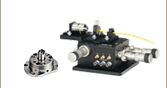
Application Idea
Aspheric Lens in a Fiber Launch Application


Please Wait
| Table 1.1 Molded Glass Aspheric Lenses |
|---|
| Infinite Conjugate |
| Uncoated |
| 350 - 700 nm (-A Coating) |
| 600 - 1050 nm (-B Coating) |
| 1050 - 1700 nm (-C Coating) |
| 1.8 - 3 µm (-D Coating) |
| 3 - 5 µm (-E Coating) |
| 8 - 12 µm (-F Coating) |
| 405 nm V-Coating |
| 1064 nm V-Coating |
| Finite Conjugate |
| Uncoated |
| Webpage Features | |
|---|---|
| |
Click for complete specifications. |
| Performance Hyperlink | Click to view item-specific focal length shift data and spot diagrams at various wavelengths. |
 Zemax Files Zemax Files |
|---|
| Click on the red Document icon next to the item numbers below to access the Zemax file download. Our entire Zemax Catalog is also available. |
Features
- Molded Glass Aspheric Lenses Designed for Infinite Magnification
- Focus or Collimate Light Without Introducing Spherical Aberration
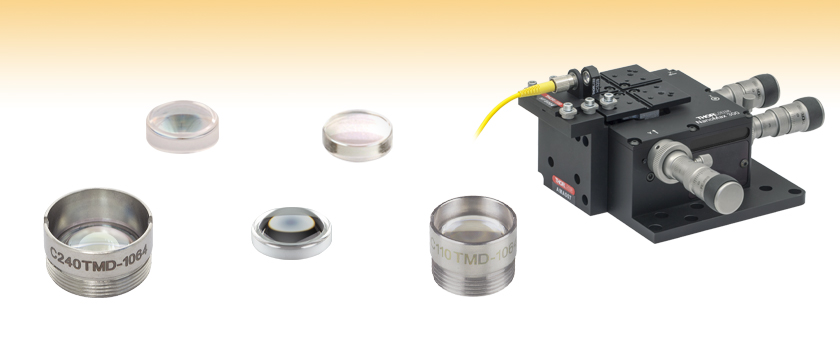
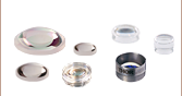
- Available Unmounted or Pre-Mounted in Non-Magnetic 303 Stainless Steel Lens Cells
Engraved with the Item # - AR Coating for Either 405 nm or 1064 nm
Aspheric lenses are designed to focus or collimate light without introducing spherical aberration into the transmitted wavefront. For monochromatic sources, spherical aberration is often what prevents a single spherical lens from achieving diffraction limited performance when focusing or collimating light. Thus, an aspheric lens is often the best single element solution for many applications including collimating the output of a fiber or laser diode, coupling light into a fiber, spatial filtering, or imaging light onto a detector.
All of the lenses featured on this page are available with an antireflective (AR) coating for either 405 nm or 1064 nm deposited on both sides. Other AR coating options are listed in Table 1.1.
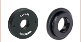
All of these molded glass lenses are also available premounted in non-magnetic 303 stainless steel lens cells that are engraved with the part number for easy identification. These mounted aspheres have a metric thread that makes them easy to integrate into an optical setup or OEM application. The mounted aspheres are readily adapted to our SM1 series of lens tubes by using our Aspheric Lens Adapters. Mounted aspheres can be used as a drop-in replacement for multi-element microscope objective by combining the lens with our Microscope Objective Adapter Extension Tube.
If an unmounted aspheric lens is being used to collimate the light from a point source or laser diode, the side with the greater radius of curvature (i.e., the flatter surface) should face the point source or laser diode. To collimate light using one of our mounted aspheric lenses, orient the housing so that the externally threaded end of the mount faces the source.
The damage threshold for these lenses is determined by the coating. As a guideline, lenses with our 1064 nm V-Coating can withstand 100 W/cm2 CW input power or 0.1 J/cm2 with 10 ns pulse time at 1064 nm. Molded glass aspheres are manufactured from a variety of optical glasses to yield the indicated performance. The molding process will cause the properties of the glass (e.g., Abbe number) to deviate slightly from those given by glass manufacturers. Specific material properties for each lens can be found by clicking on the Info Icon ![]() in the tables below and selecting the Glass tab.
in the tables below and selecting the Glass tab.
Choosing a Lens
Aspheric lenses are commonly chosen to couple incident light with a diameter of 1 - 5 mm into a single mode fiber. A simple example will illustrate the key specifications to consider when trying to choose the correct lens.
Example:
Fiber: P1-630A-FC-2
Collimated Beam Diameter Prior to Lens: Ø3 mm
The specifications for the P1-630A-FC-2, 630 nm, FC/PC single mode patch cable indicate that the mode field diameter (MFD) is 4.3 μm. This specification should be matched to the diffraction-limited spot size given by the following equation:
![]()
Here, f is the focal length of the lens, λ is the wavelength of the input light, and D is the diameter of collimated beam incident on the lens. Solving for the desired focal length of the collimating lens yields
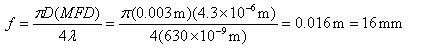
Thorlabs offers a large selection of mounted and unmounted aspheric lenses to choose from. The aspheric lens with a focal length that is closest to 16 mm has a focal length of 15.29 mm (Item# 354260-B or A260-B). This lens also has a clear aperture that is larger than the collimated beam diameter. Therefore, this aspheric lens is the best option given the initial parameters (i.e., a P1-630A-FC-2 single mode fiber and a collimated beam diameter of 3 mm). Remember, for optimum coupling the spot size of the focused beam must be less than the MFD of the single mode fiber. As a result, if an aspheric lens is not available that provides an exact match, then choose the aspheric lens with a focal length that is shorter than the calculation above yields. Alternatively, if the clear aperture of the aspheric lens is large enough, the beam can be expanded before the aspheric lens, which has the result of reducing the spot size of the focus beam.

Aspheric Lens Design Formula
| Definitions of Variables | |
|---|---|
| z | Sag (Surface Profile) as a Function of Y |
| Y | Radial Distance from Optical Axis |
| R | Radius of Curvature |
| k | Conic Constant |
| An | nth Order Aspheric Coefficient |
The aspheric surfaces of these lenses may be described using a polynomial expansion in Y, the radial distance from the optical axis. The surface profile or sagitta (often abbreviated as sag) is denoted by z, and is given by the following expression:
where R is the radius of curvature, k is the conic constant, and the An are the nth order aspheric coefficients. The sign of R is determined by whether the center of curvature for the lens surface is located to the right or left of the lens' vertex; a positive R indicates that the center of curvature is located to the right of the vertex, while a negative R indicates that the center of curvature is located to the left of the vertex. For example, the radius of curvature for the left surface of a biconvex lens would be specified as positive, while the radius of curvature for its right surface would be specified as negative.
Aspheric Lens Coefficients
Due to the rotational symmetry of the lens surface, only even powers of Y are contained in the polynomial expansion above. The target values of the aspheric coefficients for each product can be found by clicking either on the blue Info Icons in the tables below (![]() ) or on the red documents icon (
) or on the red documents icon ( ) next to each lens sold below.
Choosing a Collimation Lens for Your Laser Diode
Since the output of a laser diode is highly divergent, collimating optics are necessary. Aspheric lenses do not introduce spherical aberration and therefore are commonly chosen when the collimated laser beam is to be between one and five millimeters. A simple example will illustrate the key specifications to consider when choosing the correct lens for a given application. The second example below is an extension of the procedure, which will show how to circularize an elliptical beam.
Example 1: Collimating a Diverging Beam
- Laser Diode to be Used: L780P010
- Desired Collimated Beam Diameter: Ø3 mm (Major Axis)
When choosing a collimation lens, it is essential to know the divergence angle of the source being used and the desired output diameter. The specifications for the L780P010 laser diode indicate that the typical parallel and perpendicular FWHM beam divergences are 8° and 30°, respectively. Therefore, as the light diverges, an elliptical beam will result. To collect as much light as possible during the collimation process, consider the larger of these two divergence angles in any calculations (i.e., in this case, use 30°). If you wish to convert your elliptical beam into a round one, we suggest using an anamorphic prism pair, which magnifies one axis of your beam; for details, see Example 2 below.
Assuming that the thickness of the lens is small compared to the radius of curvature, the thin lens approximation can be used to determine the appropriate focal length for the asphere. Assuming a divergence angle of 30° (FWHM) and desired beam diameter of 3 mm:
 |
 |
||
| Θ = Divergence Angle | Ø = Beam Diameter | f = Focal Length | r = Collimated Beam Radius = Ø/2 |
Note that the focal length is generally not equal to the needed distance between the light source and the lens.
With this information known, it is now time to choose the appropriate collimating lens. Thorlabs offers a large selection of aspheric lenses. For this application, the ideal lens is a molded glass aspheric lens with focal length near 5.6 mm and our -B antireflection coating, which covers 780 nm. The C171TMD-B (mounted) or 354171-B (unmounted) aspheric lenses have a focal length of 6.20 mm, which will result in a collimated beam diameter (major axis) of 3.3 mm. Next, check to see if the numerical aperture (NA) of the diode is smaller than the NA of the lens:
0.30 = NALens > NADiode ≈ sin(15°) = 0.26
Up to this point, we have been using the full-width at half maximum (FWHM) beam diameter to characterize the beam. However, a better practice is to use the 1/e2 beam diameter. For a Gaussian beam profile, the 1/e2 diameter is almost equal to 1.7X the FWHM diameter. The 1/e2 beam diameter therefore captures more of the laser diode's output light (for greater power delivery) and minimizes far-field diffraction (by clipping less of the incident light).
A good rule of thumb is to pick a lens with an NA twice that of the laser diode NA. For example, either the A390-B or the A390TM-B could be used as these lenses each have an NA of 0.53, which is more than twice the approximate NA of our laser diode (0.26). These lenses each have a focal length of 4.6 mm, resulting in an approximate major beam diameter of 2.5 mm. In general, using a collimating lens with a short focal length will result in a small collimated beam diameter and a large beam divergence, while a lens with a large focal length will result in a large collimated beam diameter and a small divergence.
Example 2: Circularizing an Elliptical Beam
Using the laser diode and aspheric lens chosen above, we can use an anamorphic prism pair to convert our collimated, elliptical beam into a circular beam.
Whereas earlier we considered only the larger divergence angle, we now look at the smaller beam divergence of 8°. From this, and using the effective focal length of the A390-B aspheric lens chosen in Example 1, we can determine the length of the semi-minor axis of the elliptical beam after collimation:
r' = f * tan(Θ'/2) = 4.6 mm * tan(4°) = 0.32 mm
The minor beam diameter is double the semi-minor axis, or 0.64 mm. In order to magnify the minor diameter to be equal to the major diameter of 2.5 mm, we will need an anamorphic prism pair that yields a magnification of 3.9. Thorlabs offers both mounted and unmounted prism pairs. Mounted prism pairs provide the benefit of a stable housing to preserve alignment, while unmounted prism pairs can be positioned at any angle to achieve the exact desired magnification.
The PS883-B mounted prism pair provides a magnification of 4.0 for a 950 nm wavelength beam. Because shorter wavelengths undergo greater magnification when passing through the prism pair, we can expect our 780 nm beam to be magnified by slightly more than 4.0X. Thus, the beam will still maintain a small degree of ellipticity.
Alternatively, we can use the PS871-B unmounted prism pair to achieve the precise magnification of the minor diameter necessary to produce a circular beam. Using the data available here, we see that the PS871-B achieves a magnification of 4.0 when the prisms are positioned at the following angles for a 670 nm wavelength beam:
| α1: +34.608° | α2: -1.2455° |
Refer to the diagram to the right for α1 and α2 definitions. Our 780 nm laser will experience slightly less magnification than a 670 nm beam passing through the prisms at these angles. Some trial and error may be required to achieve the exact desired magnification. In general:
- To increase magnification, rotate the first prism clockwise (increasing α1) and rotate the second prism counterclockwise (decreasing α2).
- To reduce magnification, rotate the first prism counterclockwise (decreasing α1) and rotate the second prism clockwise (increasing α2).
| Table 5.1 Damage Threshold Specifications | ||
|---|---|---|
| Coating Designation (Item # Suffix) |
Type | Damage Threshold |
| -1064 | Pulsed | 0.1 J/cm2 (1064 nm, 10 ns) |
| CW | 100 W/cm2 (1064 nm) | |
Damage Threshold Data for Thorlabs' AR-Coated Molded Glass Aspheric Lenses
The specifications in Table 5.1 are measured data for Thorlabs' AR-coated molded glass aspheric lenses. Damage threshold specifications are constant for all 1064 nm AR-coated molded glass aspheric lenses, regardless of the mounting option or focal length of the lens.
Laser Induced Damage Threshold Tutorial
The following is a general overview of how laser induced damage thresholds are measured and how the values may be utilized in determining the appropriateness of an optic for a given application. When choosing optics, it is important to understand the Laser Induced Damage Threshold (LIDT) of the optics being used. The LIDT for an optic greatly depends on the type of laser you are using. Continuous wave (CW) lasers typically cause damage from thermal effects (absorption either in the coating or in the substrate). Pulsed lasers, on the other hand, often strip electrons from the lattice structure of an optic before causing thermal damage. Note that the guideline presented here assumes room temperature operation and optics in new condition (i.e., within scratch-dig spec, surface free of contamination, etc.). Because dust or other particles on the surface of an optic can cause damage at lower thresholds, we recommend keeping surfaces clean and free of debris. For more information on cleaning optics, please see our Optics Cleaning tutorial.
Testing Method
Thorlabs' LIDT testing is done in compliance with ISO/DIS 11254 and ISO 21254 specifications.
First, a low-power/energy beam is directed to the optic under test. The optic is exposed in 10 locations to this laser beam for 30 seconds (CW) or for a number of pulses (pulse repetition frequency specified). After exposure, the optic is examined by a microscope (~100X magnification) for any visible damage. The number of locations that are damaged at a particular power/energy level is recorded. Next, the power/energy is either increased or decreased and the optic is exposed at 10 new locations. This process is repeated until damage is observed. The damage threshold is then assigned to be the highest power/energy that the optic can withstand without causing damage. A histogram such as that below represents the testing of one BB1-E02 mirror.
The photograph above is a protected aluminum-coated mirror after LIDT testing. In this particular test, it handled 0.43 J/cm2 (1064 nm, 10 ns pulse, 10 Hz, Ø1.000 mm) before damage.
| Example Test Data | |||
|---|---|---|---|
| Fluence | # of Tested Locations | Locations with Damage | Locations Without Damage |
| 1.50 J/cm2 | 10 | 0 | 10 |
| 1.75 J/cm2 | 10 | 0 | 10 |
| 2.00 J/cm2 | 10 | 0 | 10 |
| 2.25 J/cm2 | 10 | 1 | 9 |
| 3.00 J/cm2 | 10 | 1 | 9 |
| 5.00 J/cm2 | 10 | 9 | 1 |
According to the test, the damage threshold of the mirror was 2.00 J/cm2 (532 nm, 10 ns pulse, 10 Hz, Ø0.803 mm). Please keep in mind that these tests are performed on clean optics, as dirt and contamination can significantly lower the damage threshold of a component. While the test results are only representative of one coating run, Thorlabs specifies damage threshold values that account for coating variances.
Continuous Wave and Long-Pulse Lasers
When an optic is damaged by a continuous wave (CW) laser, it is usually due to the melting of the surface as a result of absorbing the laser's energy or damage to the optical coating (antireflection) [1]. Pulsed lasers with pulse lengths longer than 1 µs can be treated as CW lasers for LIDT discussions.
When pulse lengths are between 1 ns and 1 µs, laser-induced damage can occur either because of absorption or a dielectric breakdown (therefore, a user must check both CW and pulsed LIDT). Absorption is either due to an intrinsic property of the optic or due to surface irregularities; thus LIDT values are only valid for optics meeting or exceeding the surface quality specifications given by a manufacturer. While many optics can handle high power CW lasers, cemented (e.g., achromatic doublets) or highly absorptive (e.g., ND filters) optics tend to have lower CW damage thresholds. These lower thresholds are due to absorption or scattering in the cement or metal coating.
LIDT in linear power density vs. pulse length and spot size. For long pulses to CW, linear power density becomes a constant with spot size. This graph was obtained from [1].
Pulsed lasers with high pulse repetition frequencies (PRF) may behave similarly to CW beams. Unfortunately, this is highly dependent on factors such as absorption and thermal diffusivity, so there is no reliable method for determining when a high PRF laser will damage an optic due to thermal effects. For beams with a high PRF both the average and peak powers must be compared to the equivalent CW power. Additionally, for highly transparent materials, there is little to no drop in the LIDT with increasing PRF.
In order to use the specified CW damage threshold of an optic, it is necessary to know the following:
- Wavelength of your laser
- Beam diameter of your beam (1/e2)
- Approximate intensity profile of your beam (e.g., Gaussian)
- Linear power density of your beam (total power divided by 1/e2 beam diameter)
Thorlabs expresses LIDT for CW lasers as a linear power density measured in W/cm. In this regime, the LIDT given as a linear power density can be applied to any beam diameter; one does not need to compute an adjusted LIDT to adjust for changes in spot size, as demonstrated by the graph to the right. Average linear power density can be calculated using the equation below.

The calculation above assumes a uniform beam intensity profile. You must now consider hotspots in the beam or other non-uniform intensity profiles and roughly calculate a maximum power density. For reference, a Gaussian beam typically has a maximum power density that is twice that of the uniform beam (see lower right).
Now compare the maximum power density to that which is specified as the LIDT for the optic. If the optic was tested at a wavelength other than your operating wavelength, the damage threshold must be scaled appropriately. A good rule of thumb is that the damage threshold has a linear relationship with wavelength such that as you move to shorter wavelengths, the damage threshold decreases (i.e., a LIDT of 10 W/cm at 1310 nm scales to 5 W/cm at 655 nm):

While this rule of thumb provides a general trend, it is not a quantitative analysis of LIDT vs wavelength. In CW applications, for instance, damage scales more strongly with absorption in the coating and substrate, which does not necessarily scale well with wavelength. While the above procedure provides a good rule of thumb for LIDT values, please contact Tech Support if your wavelength is different from the specified LIDT wavelength. If your power density is less than the adjusted LIDT of the optic, then the optic should work for your application.
Please note that we have a buffer built in between the specified damage thresholds online and the tests which we have done, which accommodates variation between batches. Upon request, we can provide individual test information and a testing certificate. The damage analysis will be carried out on a similar optic (customer's optic will not be damaged). Testing may result in additional costs or lead times. Contact Tech Support for more information.
Pulsed Lasers
As previously stated, pulsed lasers typically induce a different type of damage to the optic than CW lasers. Pulsed lasers often do not heat the optic enough to damage it; instead, pulsed lasers produce strong electric fields capable of inducing dielectric breakdown in the material. Unfortunately, it can be very difficult to compare the LIDT specification of an optic to your laser. There are multiple regimes in which a pulsed laser can damage an optic and this is based on the laser's pulse length. The highlighted columns in the table below outline the relevant pulse lengths for our specified LIDT values.
Pulses shorter than 10-9 s cannot be compared to our specified LIDT values with much reliability. In this ultra-short-pulse regime various mechanics, such as multiphoton-avalanche ionization, take over as the predominate damage mechanism [2]. In contrast, pulses between 10-7 s and 10-4 s may cause damage to an optic either because of dielectric breakdown or thermal effects. This means that both CW and pulsed damage thresholds must be compared to the laser beam to determine whether the optic is suitable for your application.
| Pulse Duration | t < 10-9 s | 10-9 < t < 10-7 s | 10-7 < t < 10-4 s | t > 10-4 s |
|---|---|---|---|---|
| Damage Mechanism | Avalanche Ionization | Dielectric Breakdown | Dielectric Breakdown or Thermal | Thermal |
| Relevant Damage Specification | No Comparison (See Above) | Pulsed | Pulsed and CW | CW |
When comparing an LIDT specified for a pulsed laser to your laser, it is essential to know the following:
LIDT in energy density vs. pulse length and spot size. For short pulses, energy density becomes a constant with spot size. This graph was obtained from [1].
- Wavelength of your laser
- Energy density of your beam (total energy divided by 1/e2 area)
- Pulse length of your laser
- Pulse repetition frequency (prf) of your laser
- Beam diameter of your laser (1/e2 )
- Approximate intensity profile of your beam (e.g., Gaussian)
The energy density of your beam should be calculated in terms of J/cm2. The graph to the right shows why expressing the LIDT as an energy density provides the best metric for short pulse sources. In this regime, the LIDT given as an energy density can be applied to any beam diameter; one does not need to compute an adjusted LIDT to adjust for changes in spot size. This calculation assumes a uniform beam intensity profile. You must now adjust this energy density to account for hotspots or other nonuniform intensity profiles and roughly calculate a maximum energy density. For reference a Gaussian beam typically has a maximum energy density that is twice that of the 1/e2 beam.
Now compare the maximum energy density to that which is specified as the LIDT for the optic. If the optic was tested at a wavelength other than your operating wavelength, the damage threshold must be scaled appropriately [3]. A good rule of thumb is that the damage threshold has an inverse square root relationship with wavelength such that as you move to shorter wavelengths, the damage threshold decreases (i.e., a LIDT of 1 J/cm2 at 1064 nm scales to 0.7 J/cm2 at 532 nm):

You now have a wavelength-adjusted energy density, which you will use in the following step.
Beam diameter is also important to know when comparing damage thresholds. While the LIDT, when expressed in units of J/cm², scales independently of spot size; large beam sizes are more likely to illuminate a larger number of defects which can lead to greater variances in the LIDT [4]. For data presented here, a <1 mm beam size was used to measure the LIDT. For beams sizes greater than 5 mm, the LIDT (J/cm2) will not scale independently of beam diameter due to the larger size beam exposing more defects.
The pulse length must now be compensated for. The longer the pulse duration, the more energy the optic can handle. For pulse widths between 1 - 100 ns, an approximation is as follows:

Use this formula to calculate the Adjusted LIDT for an optic based on your pulse length. If your maximum energy density is less than this adjusted LIDT maximum energy density, then the optic should be suitable for your application. Keep in mind that this calculation is only used for pulses between 10-9 s and 10-7 s. For pulses between 10-7 s and 10-4 s, the CW LIDT must also be checked before deeming the optic appropriate for your application.
Please note that we have a buffer built in between the specified damage thresholds online and the tests which we have done, which accommodates variation between batches. Upon request, we can provide individual test information and a testing certificate. Contact Tech Support for more information.
[1] R. M. Wood, Optics and Laser Tech. 29, 517 (1998).
[2] Roger M. Wood, Laser-Induced Damage of Optical Materials (Institute of Physics Publishing, Philadelphia, PA, 2003).
[3] C. W. Carr et al., Phys. Rev. Lett. 91, 127402 (2003).
[4] N. Bloembergen, Appl. Opt. 12, 661 (1973).
| Posted Comments: | |
Elaine Su
(posted 2021-12-22 00:50:38.37) 透镜描述里的Geltech是什么意思? YLohia
(posted 2021-12-22 02:34:04.0) Thank you for contacting Thorlabs. An applications engineer from our team in China (techsupport-cn@thorlabs.com) will discuss this directly with you. |
| Table 112A AR Coating Abbreviations | |
|---|---|
| Abbreviation | Description |
| U | Uncoated: Optics Do Not have an AR Coating |
| A | Broadband AR Coating for the 350 - 700 nm Range |
| B | Broadband AR Coating for the 600 - 1050 nm or 650 - 1050 nm Range |
| C | Broadband AR Coating for the 1050 - 1620 nm or 1050 - 1700 nm Range |
| V | Narrowband AR Coating Designed for the Wavelength Listed in Tables 112B and 112C |
Tables 112B and 112C contain all molded glass visible and near-IR aspheric lenses offered by Thorlabs. For our selection of IR molded glass aspheres, click here. The Item # listed is that of the unmounted, uncoated lens. An "X" in any of the five AR Coating Columns indicates the lens is available with that coating (note that the V coating availability is indicated with the AR coating wavelength). Table 112A defines each letter and lists the specified AR coating range. Clicking on the X takes you to the landing page where that lens (mounted or unmounted) can be purchased.
| Table 112B Finite Conjugate Aspheric Lenses | |||||||||||
|---|---|---|---|---|---|---|---|---|---|---|---|
| Base Item # | AR Coating Options | Effective Focal Length |
NA | Outer Diameter of Unmounted Lens |
Working Distance | Clear Aperture of Unmounted Lens |
|||||
| U | A | B | C | V | Unmounted | Mounted | |||||
| 355104 | X | 0.3 mm | 0.65 | 1.600 mm | S1: 0.1 mma S2: 1.0 mma |
- | S1: Ø0.29 mm S2: Ø0.48 mm |
||||
| 355465 | X | 0.5 mm | S1: 0.50 S2: 0.10 |
1.845 mm | S1: 0.3 mma S2: 2.9 mma |
- | S1: Ø0.40 mm S2: Ø0.70 mm |
||||
| 355585 | X | 0.6 mm | S1: 0.50 S2: 0.10 |
2.345 mm | S1: 0.3 mma S2: 3.0 mma |
- | S1: Ø0.35 mm S2: Ø0.66 mm |
||||
| 355587 | X | 0.6 mm | S1: 0.50 S2: 0.11 |
1.800 mm | S1: 0.3 mma S2: 2.9 mma |
- | S1: Ø0.35 mm S2: Ø0.68 mm |
||||
| 355915 | X | 0.8 mm | S1: 0.50 S2: 0.12 |
1.300 mm | S1: 0.7 mma S2: 3.9 mma |
S1: 0.6 mma,b S2: 0.8 mma,b |
S1: Ø0.77 mm S2: Ø1.00 mm |
||||
| 355200 | X | 1.1 mm | S1: 0.43 S2: 0.12 |
2.400 mm | S1: 0.5 mmc S2: 4.8 mma |
S1: 0.4 mmb,c S2: 2.4 mma,b |
S1: Ø1.24 mm S2: Ø1.24 mm |
||||
| 355201 | X | 1.1 mm | S1: 0.12 S2: 0.43 |
4.929 mm | S1: 0.5 mmc S2: 4.8 mma |
S1: 0.2 mmb,c S2: 2.6 mma,b |
S1: Ø1.24 mm S2: Ø1.24 mm |
||||
| 354450 | X | 1.2 mm | S1: 0.30 S2: 0.30 |
1.800 mm | S1: 1.7 mma S2: 1.7 mma |
- | S1: Ø1.14 mm S2: Ø1.14 mm |
||||
| 355755 | X | 1.9 mm | S1: 0.15 S2: 0.15 |
1.700 mm | S1: 3.6 mma S2: 3.6 mma |
S1: 3.5 mma,b S2: 0.9 mma,b |
S1: Ø1.10 mm S2: Ø1.10 mm |
||||
| Table 112C Infinite Conjugate Aspheric Lenses | |||||||||||
|---|---|---|---|---|---|---|---|---|---|---|---|
| Base Item # | AR Coating Options | Effective Focal Length |
NA | Outer Diameter of Unmounted Lens |
Working Distance | Clear Aperture of Unmounted Lens |
|||||
| U | A | B | C | V | Unmounted | Mounted | |||||
| 354710 | X | X | X | X | 1.5 mm | 0.53 | 2.650 mm | 0.5 mma | 0.4 mma,b | S1: Ø1.15 mm S2: Ø1.50 mm |
|
| 354140 | X | X | X | X | 1.5 mm | 0.58 | 2.400 mm | 0.8 mmc | 0.8 mmc | S1: Ø1.14 mm S2: Ø1.60 mm |
|
| 355151 | X | X | X | X | 2.0 mm | 0.50 | 3.000 mm | 0.5 mma | 0.3 mma,b | S1: Ø1.09 mm S2: Ø2.00 mm |
|
| 355440 | X | X | X | X | 2.8 mm | S1: 0.26 S2: 0.52 |
4.700 mm | S1: 2.0 mma S2: 7.1 mmc |
S1: 1.8 mma,b S2: 7.09 mmc |
S1: Ø3.76 mm S2: Ø4.12 mm |
|
| 355392 | X | X | X | X | 2.8 mm | 0.60 | 4.000 mm | 1.5 mmc | 1.0 mmb,c | S1: Ø2.50 mm S2: Ø3.60 mm |
|
| 355390 | X | X | X | X | 2.8 mm | 0.55 | 4.500 mm | 2.2 mmc | 2.0 mmb,c | S1: Ø3.60 mm S2: Ø3.60 mm |
|
| 355660 | X | X | X | X | 3.0 mm | 0.52 | 4.000 mm | 1.6 mmc | 1.3 mmb,c | S1: Ø2.35 mm S2: Ø3.60 mm |
|
| 354330 | X | X | X | X | 3.1 mm | 0.70 | 6.325 mm | 1.8 mmc | 1.8 mmb,c | S1: Ø3.84 mm S2: Ø5.00 mm |
|
| N414 | X | X | X | 3.30 mm | 0.47 | 4.50 mm | 1.94 mmc | 1.83 mmb,c | Ø3.52 mm | ||
| 354340 | X | X | X | 4.0 mm | 0.64 | 6.325 mm | 1.48 mma | 1.2 mma,b | S1: Ø3.77 mm S2: Ø5.10 mm |
||
| 357610 | X | X | X | 4.0 mm | 0.62 | 6.325 mm | 1.5 mma | 1.1 mma,b | S1: Ø3.39 mm S2: Ø4.80 mm |
||
| 357775 | X | X | X | 405 | 4.0 mm | 0.60 | 6.325 mm | 1.9 mma | 1.5 mma,b | S1: Ø3.45 mm S2: Ø4.80 mm |
|
| 354350 | X | X | X | 4.5 mm | 0.40 | 4.700 mm | 2.2 mmc | 1.6 mmb,c | S1: Ø2.05 mm S2: Ø3.70 mm |
||
| 355230 | X | X | X | X | 1064 | 4.5 mm | 0.55 | 6.325 mm | 2.8 mma | 2.4 mma,b | S1: Ø3.93 mm S2: Ø5.07 mm |
| A230 | X | X | X | X | 4.51 mm | 0.55 | 6.34 mm | 2.91 mmc | 2.53 mmb,c | Ø4.95 mm | |
| 354453 | X | X | X | X | 4.6 mm | 0.50 | 6.000 mm | 2.0 mma | 0.9 mma,b | S1: Ø3.38 mm S2: Ø4.80 mm |
|
| A390 | X | X | 4.60 mm | 0.53 | 6.00 mm | 2.70 mmc | 1.64 mmb,c | Ø4.89 mm | |||
| 354430 | X | X | X | 5.0 mm | 0.15 | 2.000 mm | 4.4 mmc | 4.0 mmb,c | S1: Ø1.40 mm S2: Ø1.60 mm |
||
| 354105 | X | X | X | X | 5.5 mm | 0.60 | 7.200 mm | 3.1 mma | 2.0 mma,b | S1: Ø4.96 mm S2: Ø6.00 mm |
|
| 354171 | X | X | X | X | 6.2 mm | 0.30 | 4.700 mm | 3.4 mma | 2.8 mma,b | S1: Ø2.72 mm S2: Ø3.70 mm |
|
| 355110 | X | X | X | X | 1064 | 6.2 mm | 0.40 | 7.200 mm | 2.7 mma | 1.6 mma,b | S1: Ø2.93 mm S2: Ø5.00 mm |
| A110 | X | X | X | X | 6.24 mm | 0.40 | 7.20 mm | 3.39 mmc | 2.39 mmb,c | Ø5.00 mm | |
| A375 | X | X | X | 7.50 mm | 0.30 | 6.51 mm | 5.90 mmc | 5.59 mmb,c | Ø4.50 mm | ||
| 354240 | X | X | X | X | 1064 | 8.0 mm | 0.50 | 9.950 mm | 4.9 mma | 3.8 mma,b | S1: Ø6.94 mm S2: Ø8.00 mm |
| A240 | X | X | X | X | 8.00 mm | 0.50 | 9.94 mm | 5.92 mmc | 4.79 mmb,c | Ø8.00 mm | |
| 354060 | X | X | X | X | 9.6 mm | 0.27 | 6.325 mm | 7.5 mma | 7.1 mma,b | S1: Ø5.13 mm S2: Ø5.20 mm |
|
| 354061 | X | X | X | X | 11.0 mm | 0.24 | 6.325 mm | 8.9 mma | 8.5 mma,b | S1: Ø4.63 mm S2: Ø5.20 mm |
|
| A220 | X | X | X | 11.00 mm | 0.26 | 7.20 mm | 7.97 mmc | 6.91 mmb,c | Ø5.50 mm | ||
| 354220 | X | X | X | X | 1064 | 11.0 mm | 0.25 | 7.200 mm | 6.9 mma | 5.8 mma,b | S1: Ø4.07 mm S2: Ø5.50 mm |
| 355397 | X | X | X | X | 11.0 mm | 0.30 | 7.200 mm | 9.3 mma | 8.2 mma,b | S1: Ø6.24 mm S2: Ø6.68 mm |
|
| A397 | X | X | X | 11.00 mm | 0.30 | 7.20 mm | 9.64 mmc | 8.44 mmb,c | Ø6.59 mm | ||
| 354560 | X | X | X | X | 13.86 mm | 0.18 | 6.325 mm | 12.1 mmc | 11.7 mmb,c | S1: Ø4.54 mm S2: Ø5.10 mm |
|
| A260 | X | X | X | 15.29 mm | 0.16 | 6.50 mm | 14.09 mmc | 13.84 mmb,c | Ø5.00 mm | ||
| 354260 | X | X | X | X | 15.3 mm | 0.16 | 6.500 mm | 12.7 mma | 12.4 mma,b | S1: Ø4.61 mm S2: Ø5.00 mm |
|
| A280 | X | X | X | 18.40 mm | 0.15 | 6.50 mm | 17.13 mmc | 16.88 mmb,c | Ø5.50 mm | ||
| 354280 | X | X | X | X | 1064 | 18.4 mm | 0.15 | 6.500 mm | 15.9 mma | 15.6 mma,b | S1: Ø5.15 mm S2: Ø5.50 mm |
| Item # (Unmounted/ Mounted) |
Info | EFLa | NA | OD | WDb | CAc | TC | DW | LWTd | Glass | Performance | Thread | Suggested Spanner Wrench |
|---|---|---|---|---|---|---|---|---|---|---|---|---|---|
| 357775-405 | 4.0 mm | 0.60 | 6.325 mm | 1.9 mme | S1: Ø3.45 mm S2: Ø4.80 mm |
2.898 mm | 408 nm | 0.250 mm | Focal Shift / Spot Size Cross Section |
- | - | ||
| C775TMD-405 | 9.2 mm | 1.5 mme,f | M9 x 0.5 | SPW301 |
- EFL is specified at the design wavelength for the unmounted lens.
- WD is specified at the design wavelength.
- S1 and S2 refer to the sides of the asphere. For more information, click on the Info Icon (
 ) next to the item number above.
 - Lenses with an LWT specification are designed for laser diode collimation; in these cases, the NA, WD, and wavefront are defined based on the presence of a laser window (not included) of the indicated thickness.
- This working distance is measured to the front of the window of the laser diode being collimated.
- Measured from the Mount
| Item # (Unmounted/ Mounted) |
Info | EFLa | NA | OD | WDb | CAc | TC | DW | LWTd | Glass | Performance | Thread | Suggested Spanner Wrench |
|---|---|---|---|---|---|---|---|---|---|---|---|---|---|
| 355230-1064 | 4.5 mm | 0.55 | 6.325 mm | 2.8 mme | S1: Ø3.93 mm S2: Ø5.07 mm |
2.708 mm | 780 nm | 0.250 mm | D-ZLaF52LA | Focal Shift / Spot Size Cross Section |
- | - | |
| C230TMD-1064 | 9.2 mm | 2.4 mme,f | M9 x 0.5 | SPW301 | |||||||||
| 355110-1064 | 6.2 mm | 0.40 | 7.200 mm | 2.7 mme | S1: Ø2.93 mm S2: Ø5.00 mm |
5.158 mm | 780 nm | 0.275 mm | D-ZLaF52LA | Focal Shift / Spot Size Cross Section |
- | - | |
| C110TMD-1064 | 9.2 mm | 1.6 mme,f | M9 x 0.5 | SPW301 | |||||||||
| 354240-1064 | 8.0 mm | 0.50 | 9.936 mm | 4.9 mme | S1: Ø6.94 mm S2: Ø8.00 mm |
3.434 mm | 780 nm | 0.250 mm | D-ZK3 | Focal Shift / Spot Size Cross Section |
- | - | |
| C240TMD-1064 | 12.2 mm | 3.8 mme,f | SPW302 | ||||||||||
| 354220-1064 | 11.0 mm | 0.25 | 7.200 mm | 6.9 mme | S1: Ø4.07 mm S2: Ø5.50 mm |
5.032 mm | 633 nm | 0.250 mm | D-ZK3 | Focal Shift / Spot Size Cross Section |
- | - | |
| C220TMD-1064 | 9.2 mm | 5.8 mme,f | M9 x 0.5 | SPW301 | |||||||||
| 354280-1064 | 18.4 mm | 0.15 | 6.500 mm | 15.9 mme | S1: Ø5.15 mm S2: Ø5.50 mm |
2.178 mm | 780 nm | 0.250 mm | D-ZK3 | Focal Shift / Spot Size Cross Section |
- | - | |
| C280TMD-1064 | 9.2 mm | 15.6 mme,f | M9 x 0.5 | SPW301 |
- EFL is specified at 1064 nm rather than at the design wavelength.
- WD is specified at the design wavelength.
- S1 and S2 refer to the sides of the asphere. For more information, click on the Info Icon () next to the item number above.
- Lenses with an LWT specification are designed for laser diode collimation; in these cases, the NA, WD, and wavefront are defined based on the presence of a laser window (not included) of the indicated thickness.
- This working distance is measured to the front of the window of the laser diode being collimated.
- Measured from the Mount