 Products Home
IR Free-Space Isolators (1110 - 2100 nm)
- Isolation Up to 60 dB
- Power Densities Up to 250 W/cm2
- Custom Isolators Available Upon Request
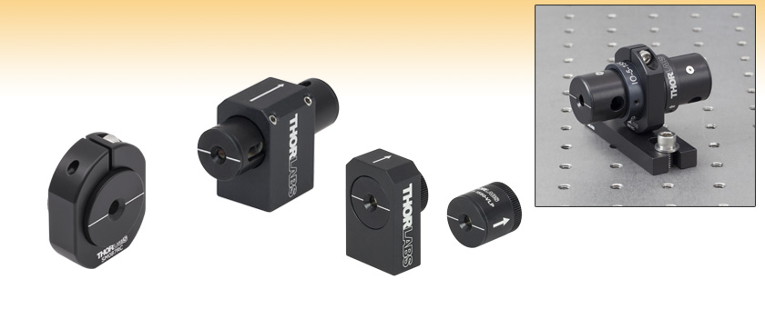
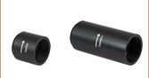
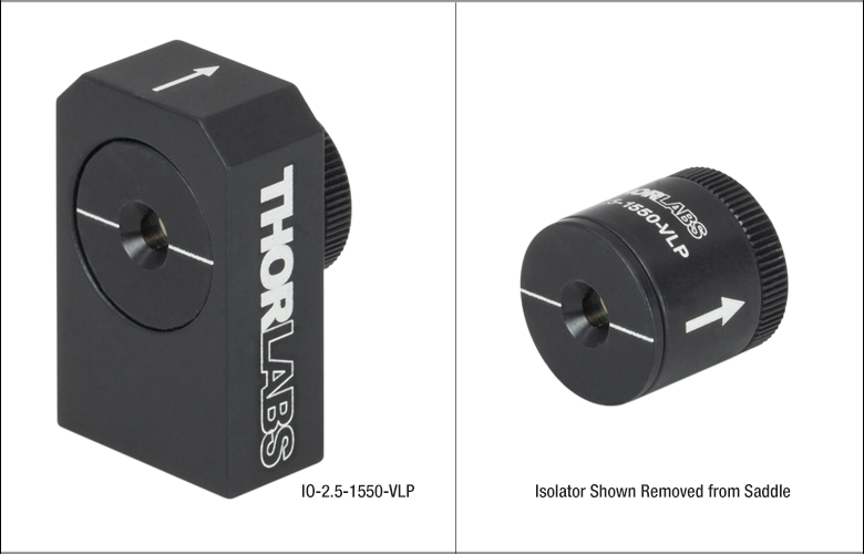
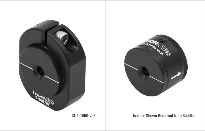
IO-4-1650-VLP
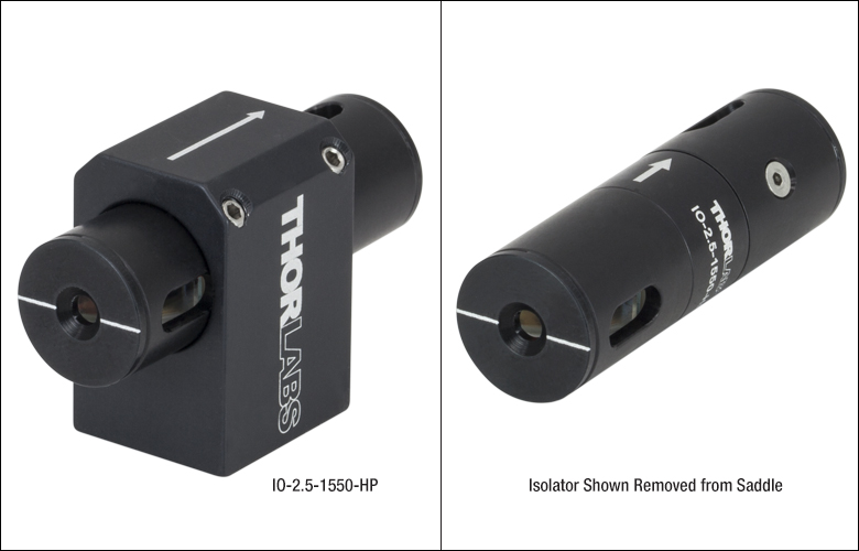
IO-2.5-1550-HP
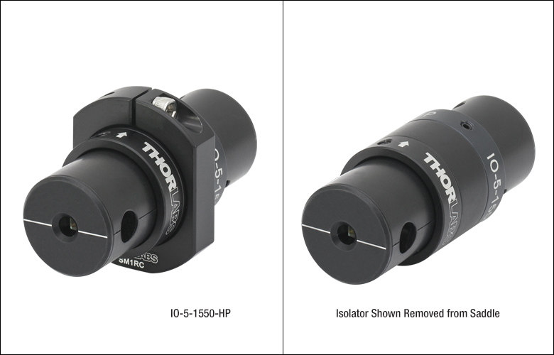
In Saddle
IO-2.5-1550-VLP
Removed
from Saddle
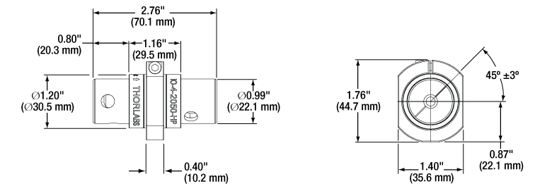
IO-5-1550-HP
Shown in the Saddle (SM1RC) Mounted on
an Optical Table Using a BA1 Base with an
SD1 1/4"-20 to 8-32 Counterbore Adapter


Please Wait
Click to Enlarge
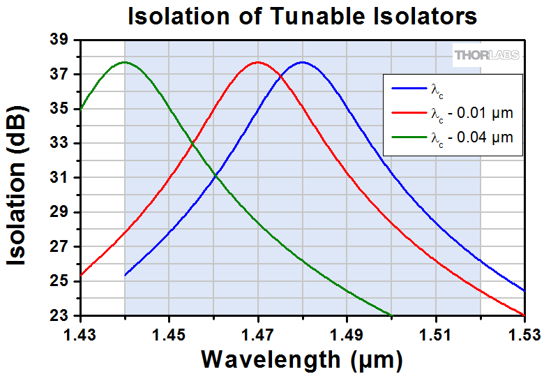
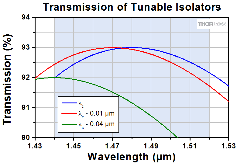
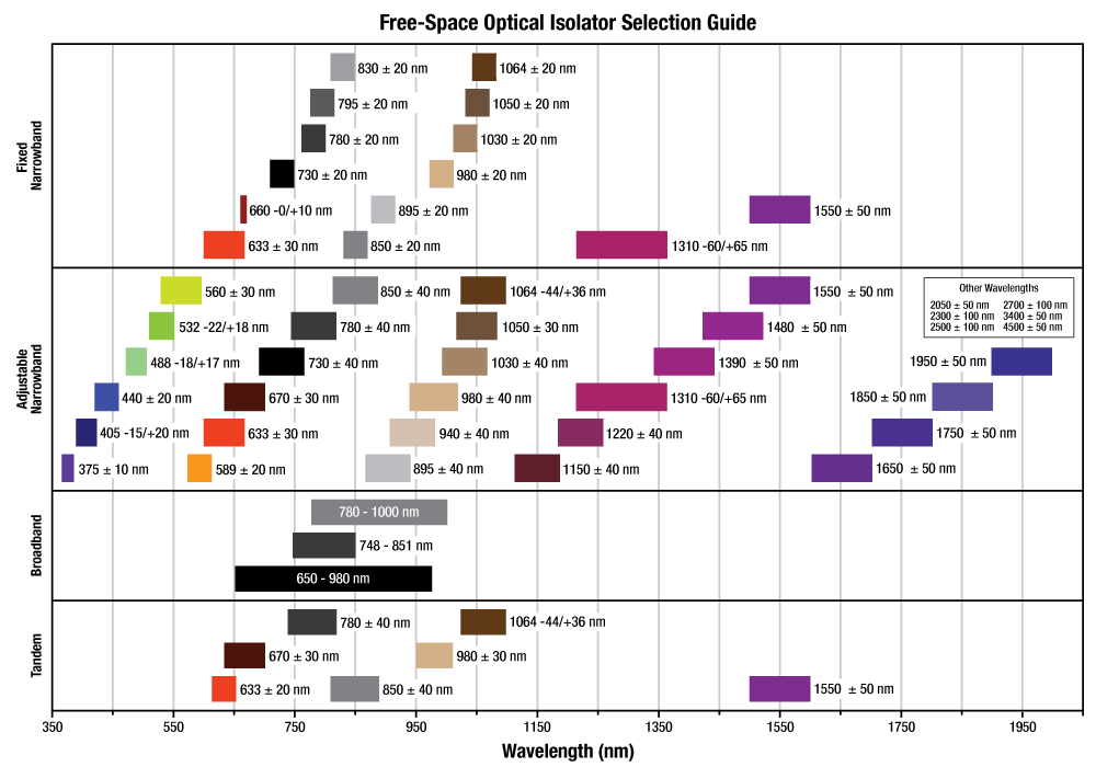
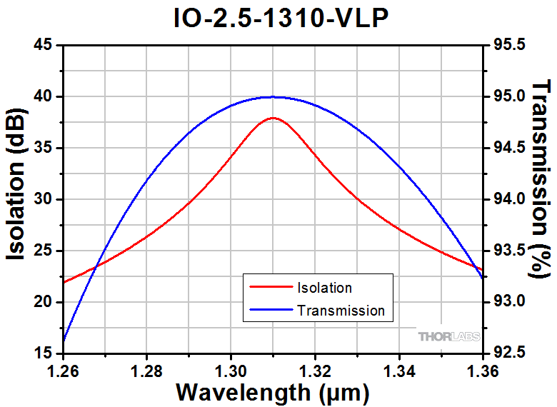
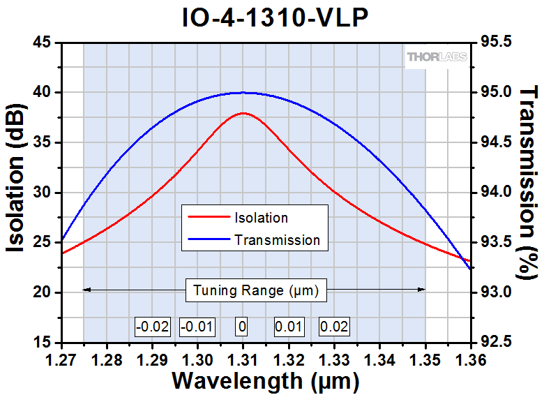
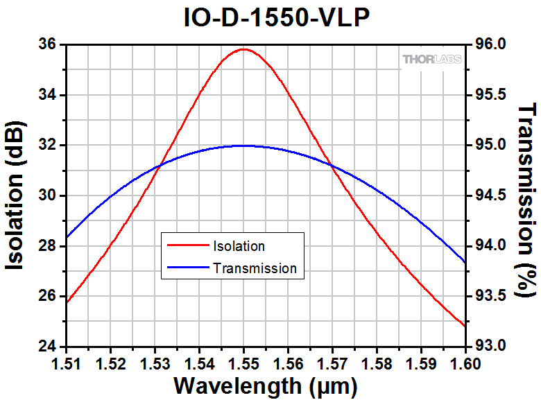
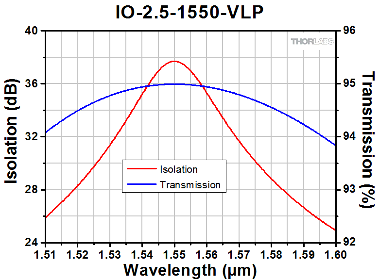
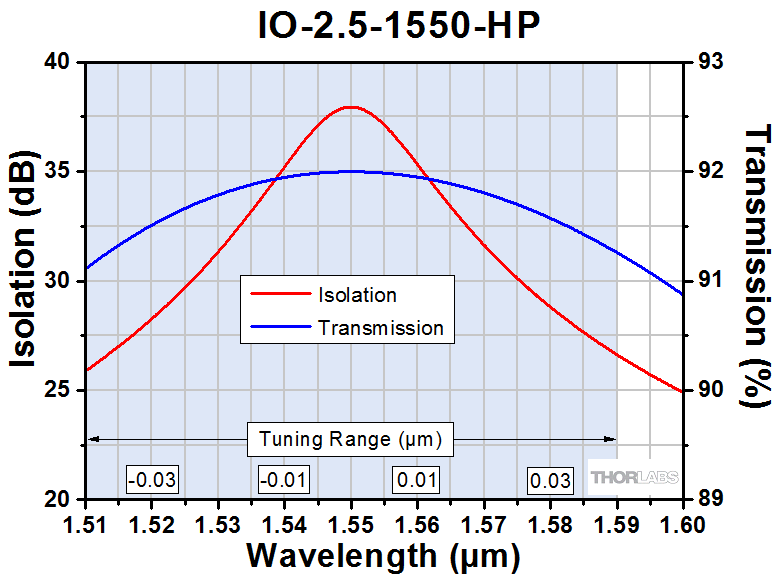
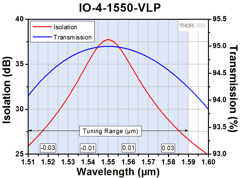
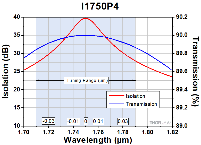
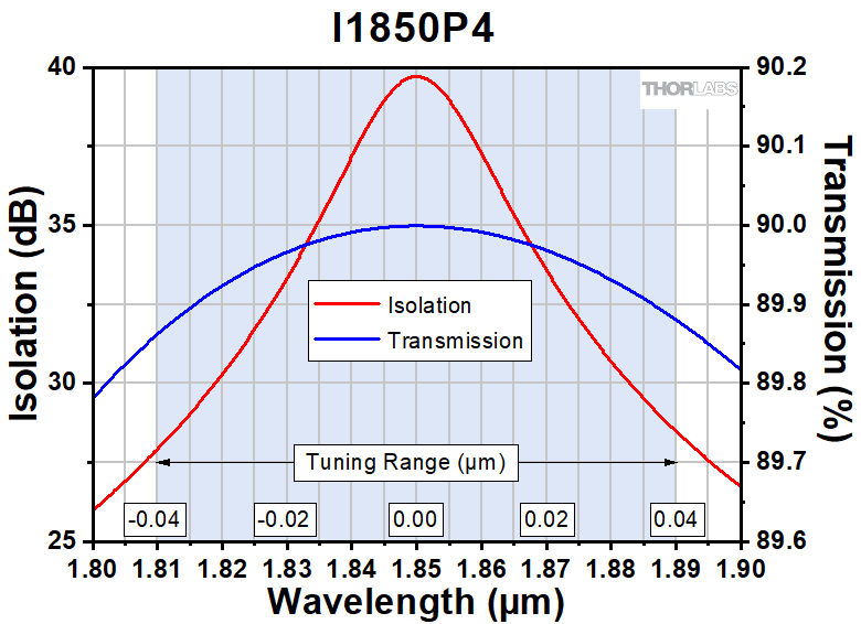
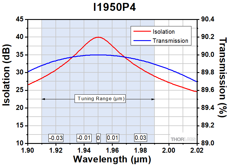
Our Adjustable Narrowband Isolators can be tuned from the design center wavelength (λc) to maximize the peak isolation for any wavelength within a narrow spectral range (shaded in this graph). See the Wavelength Tuning tab for more details.
Custom Isolators
- Customizable Wavelength, Aperture, Max Power, Housing, Polarizers, and Operating Temperature
- Pricing Similar to Stock Units
- Wide Range of OEM Capabilities
- Please Contact Tech Support or See Our Custom Isolators Page
Click to Enlarge
Many of our isolators, such as the
IO-3D-1064-VLP, can be ordered in custom packages for use in FiberBench systems by contacting Tech Support.
Features
- 11 Center Wavelength Options from 1150 nm to 2050 nm
- Fixed or Tunable Wavelength Ranges
- Free-Space Input and Output Ports
- Peak Isolation from 28 to 60 dB
- Apertures up to Ø4.7 mm
- Polarization-Dependent Input
Thorlabs is pleased to stock a variety of free-space optical isolators designed for use in the infrared spectral range (1110 - 2100 nm). Optical isolators, also known as Faraday isolators, are magneto-optic devices that preferentially transmit light along a single direction, shielding upstream optics from back reflections. Back reflections can create a number of instabilities in light sources, including intensity noise, frequency shifts, mode hopping, and loss of mode lock. In addition, intense back-reflected light can permanently damage optics. Please see the Isolator Tutorial tab for an explanation of the operating principles of a Faraday isolator.
| Selection Guide for Isolators (Click Here for Our Full Selection) |
|---|
| Wavelength Range |
| 365 - 385 nm (UV) |
| 390 - 700 nm (Visible) |
| 690 - 1080 nm (NIR) |
| 1064 nm (Nd:YAG) |
| 1110 - 2100 nm (IR) |
| 2.20 - 4.55 µm (MIR) |
| Broadband |
| Fiber Isolators |
| Custom Isolators |
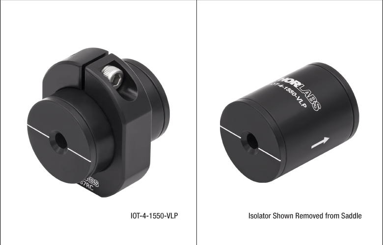
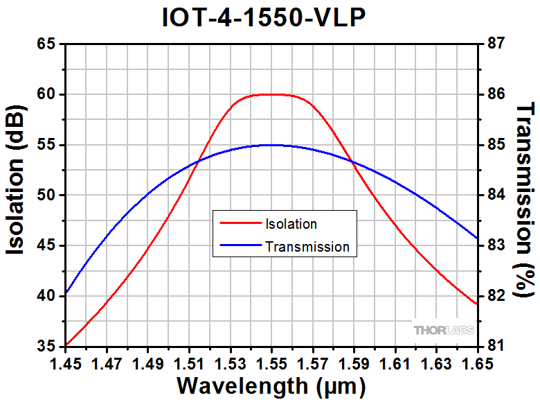
In the infrared wavelength range, we offer three types of isolators. The first type, Fixed Narrowband Isolators, contains fixed, factory-aligned optics, for which peak isolation and peak transmission occur at a pre-defined center wavelength. Any deviation from this wavelength will cause a dip in isolation and transmission. The second type, Adjustable Narrowband Isolators, offers the user the ability to adjust the alignment of the input and output polarizers, allowing tuning of the center wavelength within a 60 - 100 nm range, depending upon the exact isolator. The third type, Tandem Fixed Narrowband Isolators (IOT-4-1550-VLP), consists of two Faraday rotators in series, boosting the isolation to 60 dB at the expense of lower transmission. Please see the Isolator Types tab for additional design details and representative graphs of the wavelength-dependent isolation.
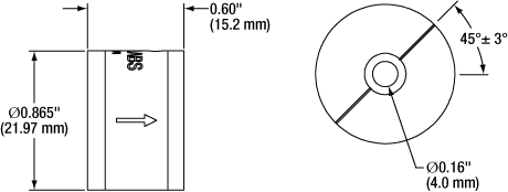
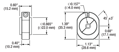
The housing of each isolator shown here, except for the IO-D-1550-VLP, is marked with an arrow that indicates the direction of forward propagation. The input and output apertures of the IO-D-1550-VLP are indicated by the black and gold coloring of the cylinder, respectively. All isolators shown here (including the IO-D-1550-VLP) have engravings that indicate the alignment of the input and output polarizers.
Thorlabs also manufactures isolators for fiber optic systems and wavelengths down into the visible (see the Selection Guide table to the left). As indicated in the tables below and pictured to the right, many of our stock isolators can also be provided in a mount designed for our FiberBench systems. If Thorlabs does not stock an isolator suited for your application, please refer to the Custom Isolators tab for information on our build-to-order options, or contact Tech Support. Thorlabs' in-house manufacturing service has over 25 years of experience and can deliver a free-space isolator tuned to your center wavelength from 365 nm to 4.55 µm. Our vertically integrated manufacturing structure allows us to offer Faraday rotators used in optical isolators. We offer a selection of Faraday rotators from stock and can provide custom Faraday rotators upon request.
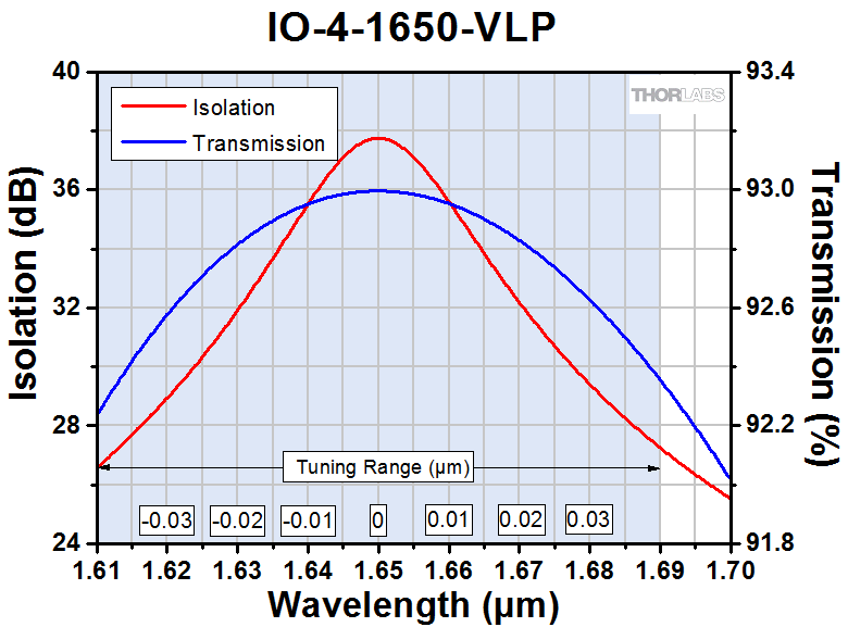
Shaded regions on a graph represent the center wavelength tuning range of the isolator. With these isolators, the isolation and transmission curves will shift as the center wavelength shifts. If the graph is not shaded, then the isolator is non-tunable. Please note that these curves were made from theoretical data and that isolation and transmission will vary from unit to unit.
Tuning an Adjustable Narrowband Isolator
- Optimize Our Isolators to Provide the Same Peak Isolation Anywhere Within Their Tuning Range
- Simple Tuning Procedure, Illustrated Below, Consists Primarily of Rotating the Output Polarizer
- Slight Transmission Losses Occur Due to Polarizer Rotation
Click to Enlarge
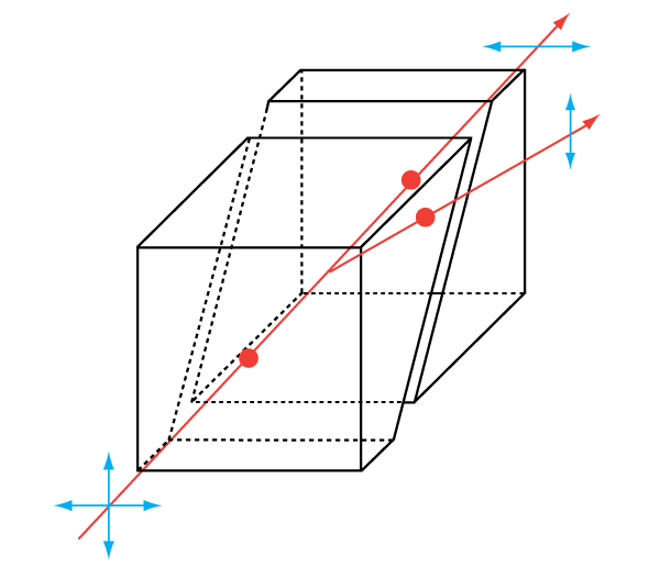
When the isolator is tuned away from its design center wavelength (λc), the maximum transmission falls because the output polarizer's transmission axis is not parallel to the polarization direction of the output light.
Click to Enlarge
Our Adjustable Narrowband Isolators can be tuned from the design center wavelength (λc) to maximize the peak isolation for any wavelength within a narrow spectral range (shaded in this graph).
Click to Enlarge
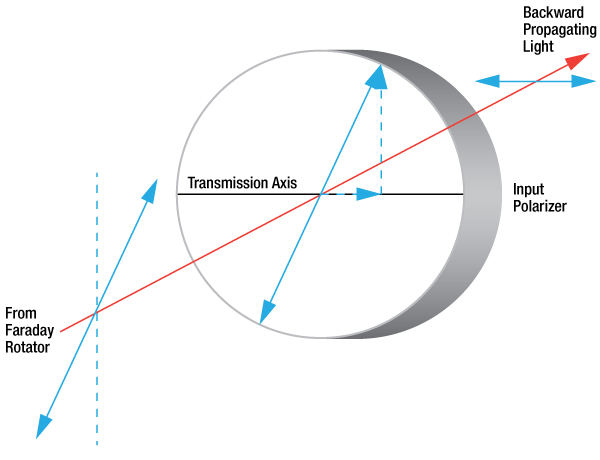
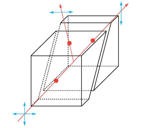
Light Not at the Design Wavelength is Partially Transmitted
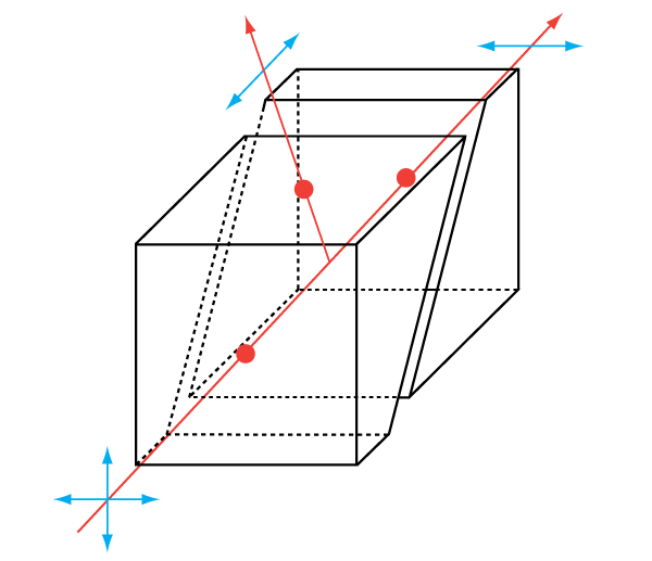
Click to Enlarge
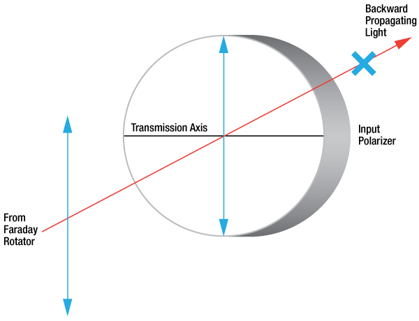
Light at the Design Wavelength is Rejected
Operating Principles of Optical Isolators
Thorlabs' Adjustable Narrowband Isolators are designed to provide the same peak isolation anywhere within a 60 - 100 nm tuning range. They contain a Faraday rotator that has been factory tuned to rotate light of the design wavelength by 45°. Light propagating through the isolator in the backward direction is polarized at 45° by the output polarizer and is rotated by 45° by the Faraday rotator, giving a net polarization of 90° relative to the transmission axis of the input polarizer. Therefore, an isolator rejects backward propagating light. See the Isolator Tutorial tab for a schematic of the beam path.
The magnitude of the rotation caused by the Faraday rotator is wavelength dependent. This means that light with a different wavelength than the design wavelength will not be rotated at exactly 45°. For example, if 1480 nm light is rotated by 45° (that is, 1480 nm is the design wavelength), then 1470 nm light is rotated by 45.7°. If 1470 nm light is sent backward through an isolator designed for 1480 nm without any tweaking, it will have a net polarization of 45° + 45.7° = 90.7° relative to the axis of the input polarizer. The polarization component of the light parallel to the input polarizer's axis will be transmitted, and the isolation will therefore be significantly reduced.
Since the net polarization needs to be 90° to obtain high isolation, the output polarizer is rotated to compensate for the extra rotation being caused by the Faraday isolator. In our example, the new polarizer angle is 90° - 45.7° = 44.3°. This adjustment increases the isolation back to the same value as at the design wavelength.
Consequences of Wavelength Tuning Procedure
As a direct consequence of rotating the output polarizer, the maximum transmission in the forward direction decreases. 1470 nm light propagating in the forward direction is polarized at 0° by the input polarizer and rotated by 45.7° by the Faraday rotator, but the output polarizer is now at 44.3°. The amount of the transmission decrease can be quantified using Malus' Law:
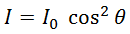
Malus' Law
Here, θ is the angle between the polarization direction of the light after the Faraday rotator and the transmission axis of the polarizer, I0 is the incident intensity, and I is the transmitted intensity. For small deviations from the center wavelength, the decrease in transmission is very slight, but for larger deviations, the decrease becomes noticeable. In our example (a 10 nm difference between the design wavelength and the usage wavelength), θ = 45.7° - 44.3° = 1.4°, so I = 0.9994 I0. This case is shown in the graphs above.
In applications, the decrease in transmission caused by the tuning procedure is usually less important than the significantly enhanced isolation gained by tuning. For example, if the 1480 nm isolator shown in the graphs above were used at 1440 nm without tuning, the transmission would be 92.1% (instead of 92.0%), but the isolation would be only 25 dB (instead of 38 dB). This case is also shown in the graphs above.
Thorlabs' isolator housings make it easy to rotate the output polarizer without disturbing the rest of the isolator. Our custom isolator manufacturing service (see the Custom Isolators tab) can also provide an isolator specifically designed for a particular center wavelength, which can eliminate or strongly mitigate the transmission losses that occur at the edges of the tuning range. These custom isolators are provided at the same cost as their equivalent stock counterparts. For more information, please contact Technical Support.
Illustrated Tuning Procedure
To optimize the isolation curve for a specific wavelength within the tuning range, the alignment of the output polarizer may be tweaked following the simple procedure outlined below. Only a minor adjustment is necessary to cover a range of several nanometers. The procedure differs slightly for different isolator packages, but the principle remains the same across our entire isolator family, and complete model-specific tuning instructions ship with each isolator.
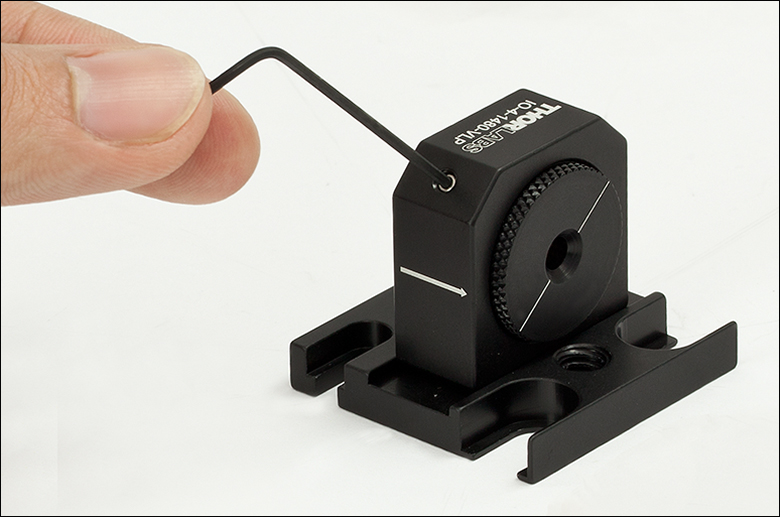
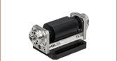
Step 1:
Orient the isolator in the backward direction with respect to the beam (i.e., with the arrow pointing antiparallel to the beam propagation direction). A power meter with high sensitivity at low power levels should be placed after the isolator.
Use the included 5/64" hex key to loosen the isolator from its saddle.
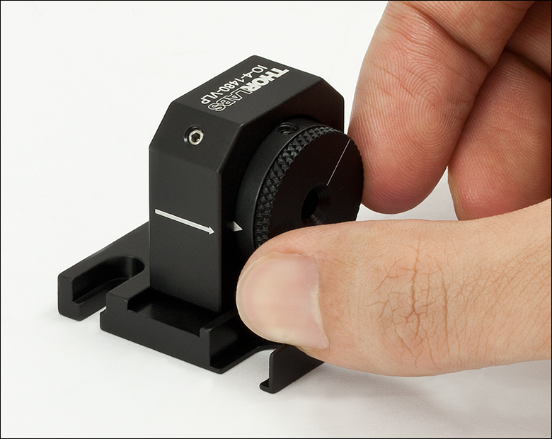
Step 2:
Grip the isolator by the sides and gently bring it out of its saddle. It is only necessary to bring it out far enough to expose the 8-32 setscrew at the top, as shown in the photo to the left.
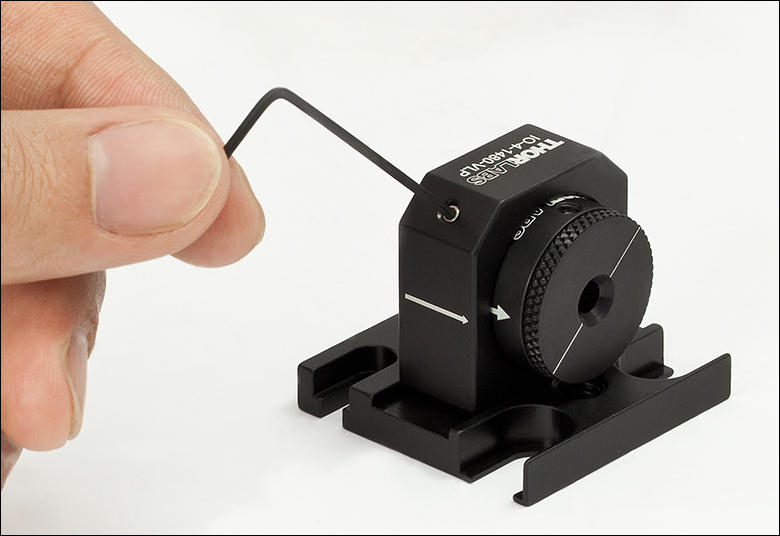
Step 3:
Use the included 5/64" hex key to tighten the isolator back into its saddle with the 8-32 setscrew exposed.
The isolator is mechanically stable in this position as long as the isolator has not been brought forward too much. (The amount shown in the image to the left is safe by several millimeters.) It should therefore not be necessary to reinsert the isolator at the end of the tuning procedure.
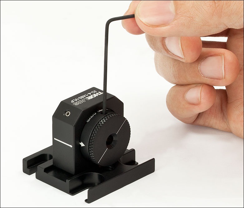
Step 4:
Loosen the exposed 8-32 setscrew using the included 5/64" hex key. At this point, the output polarizer will be free to rotate.
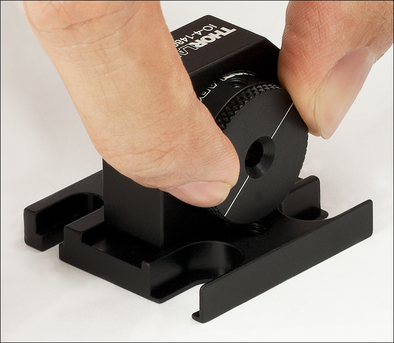
Step 5:
Rotate the output polarizer to minimize the power on the power meter. As explained above, the necessary adjustment should be only a few degrees, depending upon the desired center wavelength. Tighten the 8-32 setscrew once optimization is achieved.
As long as the isolator was not brought forward too much at the end of Step 2, the isolator will be mechanically stable in this position. Attempting to reinsert the isolator at this point may cause misalignment.
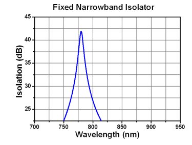
Fixed Narrowband Isolator
The isolator is set for 45° of rotation at the design wavelength. The polarizers are non-adjustable and are set to provide maximum isolation at the design wavelength. As the wavelength changes the isolation will drop; the graph shows a representative profile.
- Fixed Rotator Element, Fixed Polarizers
- Polarization Dependent
- Smallest and Least Expensive Isolator Type
- No Tuning
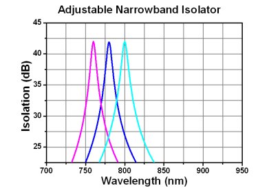
Adjustable Narrowband Isolator
The isolator is set for 45° of rotation at the design wavelength. If the usage wavelength changes, the Faraday rotation will change, thereby decreasing the isolation. To regain maximum isolation, the output polarizer can be rotated to "re-center" the isolation curve. This rotation causes transmission losses in the forward direction that increase as the difference between the usage wavelength and the design wavelength grows.
- Fixed Rotator Element, Adjustable Polarizers
- Polarization Dependent
- General-Purpose Isolator
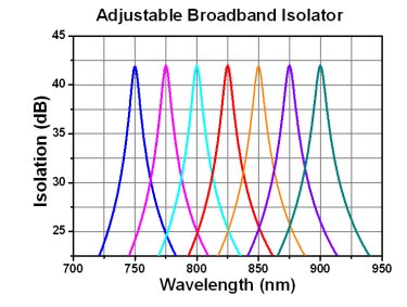
Adjustable Broadband Isolator
The isolator is set for 45° of rotation at the design wavelength. There is a tuning ring on the isolator that adjusts the amount of Faraday rotator material that is inserted into the internal magnet. As your usage wavelength changes, the Faraday rotation will change, thereby decreasing the isolation. To regain maximum isolation, the tuning ring is adjusted to produce the 45° of rotation necessary for maximum isolation.
- Adjustable Rotator Element, Fixed Polarizers
- Polarization Dependent
- Simple Tuning Procedure
- Broader Tuning Range than Adjustable Narrowband Isolators
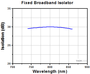
Fixed Broadband Isolator
A 45° Faraday rotator is coupled with a 45° crystal quartz rotator to produce a combined 90° rotation on the output. The wavelength dependences of the two rotator materials work together to produce a flat-top isolation profile. The isolator does not require any tuning or adjustment for operation within the designated design bandwidth.
- Fixed Rotator Element, Fixed Polarizers
- Polarization Dependent
- Largest Isolation Bandwidth
- No Tuning Required
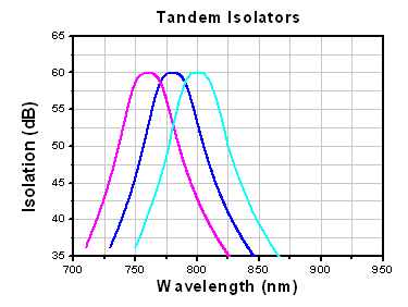
Tandem Isolators
Tandem isolators consist of two Faraday rotators in series, which share one central polarizer. Since the two rotators cancel each other, the net rotation at the output is 0°. Our tandem designs yield narrowband isolators that may be fixed or adjustable.
- Up to 60 dB Isolation
- Polarization Dependent
- Highest Isolation
- Fixed or Adjustable
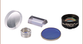
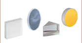
Polarizer Types, Sizes, and Power Limits
Thorlabs designs and manufactures several types of polarizers that are used across our family of optical isolators. Their design characteristics are detailed here. The part number of given isolator has an identifier for the type of polarizer that isolator contains. For more details on how the part number describes each isolator, see the given isolator's manual.
| Polarizer Comparison | |||
|---|---|---|---|
| Type | Schematic (Click to Enlarge) |
Maximum Power Density | Description |
| Very Low Power (C) |
 |
10 W/cm2 (CW, Blocking) 25 W/cm2 (CW, Transmission) |
Our Very Low Power Absorptive Film Polarizers are compact options for isolating free-space beams. For light polarized perpendicular to the polarizer's transmission axis, the max power density is 10 W/cm2, while for light polarized parallel to the polarizer's transmission axis, the max power density is 25 W/cm2. |
| Very Low Power (P or VLP) |
|
25 W/cm2 (CW, Blocking) 100 W/cm2 (CW, Transmission) |
These polarizers are also for use with very low power sources but are made with a different material than the type C polarizers listed above. This gives these polarizers a higher maximum power density. For light polarized perpendicular to the polarizer's transmission axis, the max power density is 25 W/cm2, while for light polarized parallel to the polarizer's transmission axis, the max power density is 100 W/cm2. |
| Wire Grid (W) |
|
25 W/cm2 (CW) | Wire Grid Polarizers are used in our mid-IR isolators. They consist of a linearly spaced wire grid pattern that is deposited onto an AR-coated silicon substrate. |
| Polarizing Beamsplitter (PBS) |
 |
13 - 50 W/cm2 (CW) | Polarizing Beamsplitter Cubes are commonly used in low-power applications and feature an escape window useful for monitoring or injection locking. |
| α-BBO Glan-Laser (GLB) |
 |
100 W/cm2 (CW) | Thorlabs' α-BBO Glan-Laser polarizers are all based on high-grade, birefringent, α-BBO crystals with a wavelength range of 210 - 450 nm. Due to the birefringent structure of α-BBO, a phase delay is created between two orthogonally polarized waves traveling in the crystal. These are similar to the High Power (HP) polarizers, but have a different escape angle. |
| Low Power (LP) |
 |
250 W/cm2 (CW) 25 MW/cm2 (Pulsed) |
Our Low Power Polarizers are Glan-type, crystal polarizers, providing high transmission and power densities at the expense of a larger package than Very Low Power (VLP) and Polarizing Beamsplitter (PBS) polarizers. |
| Medium Power (MP) |
 |
100 W/cm2 (CW) 50 MW/cm2 (Pulsed) |
Medium Power Polarizers are Glan-type, crystal polarizers, capable of handling higher powers. The rejected beam is internally scattered, which reduces the maximum power density, but also eliminates a stray beam from the setup. |
| High Power (HP) |
|
500 W/cm2 (CW) 150 MW/cm2 (Pulsed) |
High Power Polarizers are Glan-type, crystal polarizers, similar in size and transmission to Medium Power (MP) polarizers, but capable of handling higher powers. They feature an escape window suited for injection locking. |
| Yttrium Orthovanadate (YV) |
|
25 W/cm2 (CW) | YV polarizers are similar to the Medium Power (MP) Glan-type crystal polarizers; however, by using yttrium orthovanadate (YVO4) rather than calcite, YV polarizers can accommodate wavelengths in the 2.0 - 3.4 µm range. The rejected beam is internally scattered, which reduces the maximum power density, but also eliminates a stray beam from the setup. |
| Very High Power (VHP) |
 |
20 kW/cm2 (CW) 2 GW/cm2 (Pulsed) |
Our Very High Power Polarizers are based on Brewster windows and feature the highest power handling possible. These polarizers have larger packages than HP-based designs, but are also more economical. All VHP-based designs also feature escape windows. |
Video Insight: How to Align an Optical Isolator
To ensure optimal transmission of optical power from the source, as well as effective suppression of reflections traveling back towards the source, the Faraday isolator must be properly aligned. Alignment is demonstrated using an IO-3-532-LP polarization-dependent free-space isolator with a 510 nm to 550 nm operating range, an R2T post collar, a PL201 linearly polarized and collimated 520 nm laser, a S120C silicon power sensor, and a PM400 power meter.
If you would like more information about tips, tricks, and other methods we often use in the lab, we recommend our other Video Insights. In addition, our webinars provide practical and theoretical introductions to our different products.
Optical Isolator Tutorial
Function
An optical isolator is a passive magneto-optic device that only allows light to travel in one direction. Isolators are used to protect a source from back reflections or signals that may occur after the isolator. Back reflections can damage a laser source or cause it to mode hop, amplitude modulate, or frequency shift. In high-power applications, back reflections can cause instabilities and power spikes.
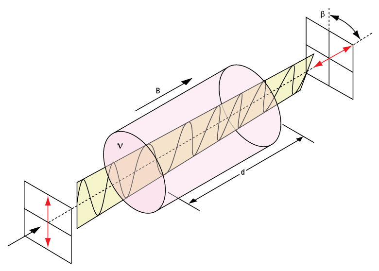
An isolator's function is based on the Faraday Effect. In 1842, Michael Faraday discovered that the plane of polarized light rotates while transmitting through glass (or other materials) that is exposed to a magnetic field. The direction of rotation is dependent on the direction of the magnetic field and not on the direction of light propagation; thus, the rotation is non-reciprocal. The amount of rotation β equals V x B x d, where V, B, and d are as defined below.
Click to Enlarge
Figure 54A Faraday Rotator's Effect on Linearly Polarized Light
Faraday Rotation
β = V x B x d
V: the Verdet Constant, a property of the optical material, in radians/T • m.
B: the magnetic flux density in teslas.
d: the path length through the optical material in meters.
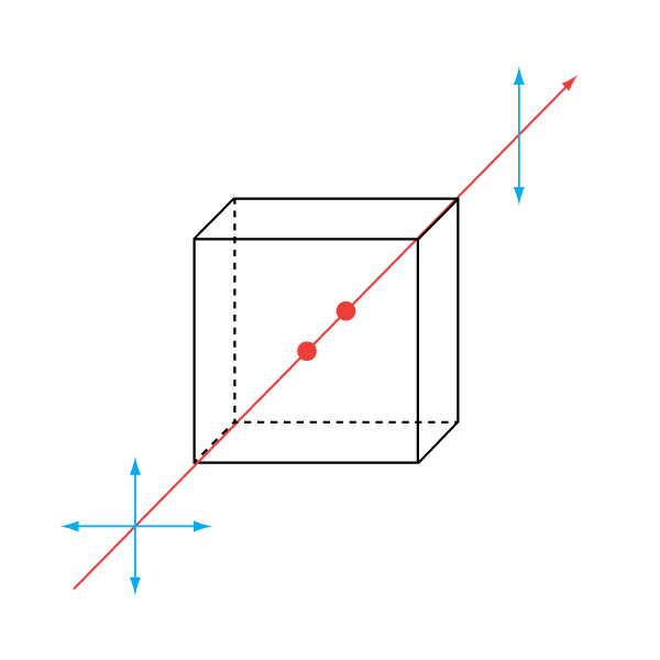
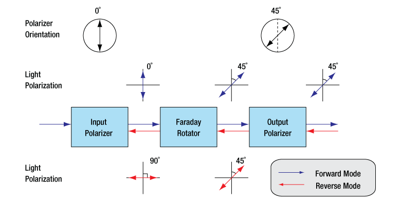
An optical isolator consists of an input polarizer, a Faraday rotator with magnet, and an output polarizer. The input polarizer works as a filter to allow only linearly polarized light into the Faraday rotator. The Faraday element rotates the input light's polarization by 45°, after which it exits through another linear polarizer. The output light is now rotated by 45° with respect to the input signal. In the reverse direction, the Faraday rotator continues to rotate the light's polarization in the same direction that it did in the forward direction so that the polarization of the light is now rotated 90° with respect to the input signal. This light's polarization is now perpendicular to the transmission axis of the input polarizer, and as a result, the energy is either reflected or absorbed depending on the type of polarizer.
Click to Enlarge
Figure 54B A single-stage, polarization-dependent isolator. Light propagating in the reverse direction is rejected by the input polarizer.
Polarization-Dependent Isolators
The Forward Mode
In this example, we will assume that the input polarizer's axis is vertical (0° in Figure 54B). Laser light, either polarized or unpolarized, enters the input polarizer and becomes vertically polarized. The Faraday rotator will rotate the plane of polarization (POP) by 45° in the positive direction. Finally, the light exits through the output polarizer which has its axis at 45°. Therefore, the light leaves the isolator with a POP of 45°.
In a dual-stage isolator, the light exiting the output polarizer is sent through a second Faraday rotator followed by an additional polarizer in order to achieve greater isolation than a single-stage isolator.
The Reverse Mode
Light traveling backwards through the isolator will first enter the output polarizer, which polarizes the light at 45° with respect to the input polarizer. It then passes through the Faraday rotator rod, and the POP is rotated another 45° in the positive direction. This results in a net rotation of 90° with respect to the input polarizer, and thus, the POP is now perpendicular to the transmission axis of the input polarizer. Hence, the light will either be reflected or absorbed.
 Click for Details
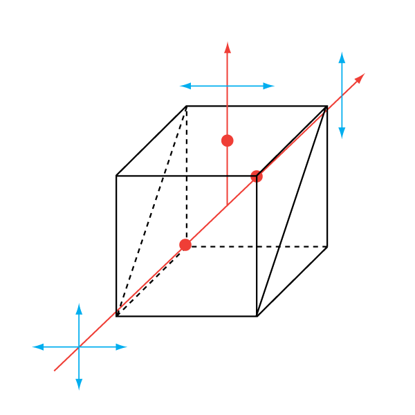
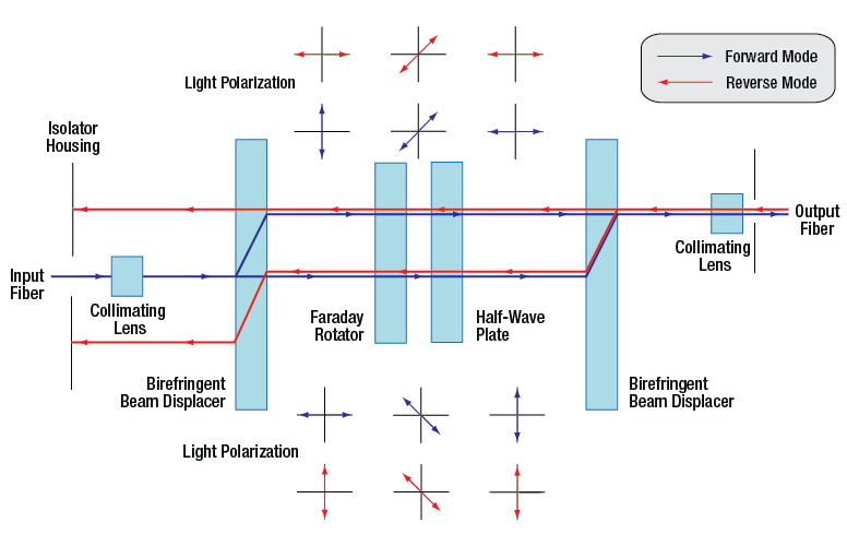
Figure 54C A single-stage, polarization-independent isolator. Light is deflected away from the input path and stopped by the housing.
Polarization-Independent Fiber Isolators
The Forward Mode
In a polarization independent fiber isolator, the incoming light is split into two branches by a birefringent crystal (see Figure 54C). A Faraday rotator and a half-wave plate rotate the polarization of each branch before they encounter a second birefringent crystal aligned to recombine the two beams.
In a dual-stage isolator, the light then travels through an additional Faraday rotator, half-wave plate, and birefringent beam displacer before reaching the output collimating lens. This achieves greater isolation than the single-stage design.
The Reverse Mode
Back-reflected light will encounter the second birefringent crystal and be split into two beams with their polarizations aligned with the forward mode light. The faraday rotator is a non-reciprocal rotator, so it will cancel out the rotation introduced by the half wave plate for the reverse mode light. When the light encounters the input birefringent beam displacer, it will be deflected away from the collimating lens and into the walls of the isolator housing, preventing the reverse mode from entering the input fiber.
General Information
Damage Threshold
With 25 years of experience and 5 U.S. patents, our isolators typically have higher transmission and isolation than other isolators, and are smaller than other units of equivalent aperture. For visible to YAG laser Isolators, Thorlabs' Faraday Rotator crystal of choice is TGG (terbium-gallium-garnet), which is unsurpassed in terms of optical quality, Verdet constant, and resistance to high laser power. Thorlabs' TGG Isolator rods have been damage tested to 22.5 J/cm2 at 1064 nm in 15 ns pulses (1.5 GW/cm2), and to 20 kW/cm2 CW. However, Thorlabs does not bear responsibility for laser power damage that is attributed to hot spots in the beam.
Magnet
The magnet is a major factor in determining the size and performance of an isolator. The ultimate size of the magnet is not simply determined by magnetic field strength but is also influenced by the mechanical design. Many Thorlabs magnets are not simple one piece magnets but are complex assemblies. Thorlabs' modeling systems allow optimization of the many parameters that affect size, optical path length, total rotation, and field uniformity. Thorlabs' US Patent 4,856,878 describes one such design that is used in several of the larger aperture isolators for YAG lasers. Thorlabs emphasizes that a powerful magnetic field exists around these Isolators, and thus, steel or magnetic objects should not be brought closer than 5 cm.
Temperature
The magnets and the Faraday rotator materials both exhibit a temperature dependence. Both the magnetic field strength and the Verdet Constant decrease with increased temperature. For operation greater than ±10 °C beyond room temperature, please contact Technical Support.
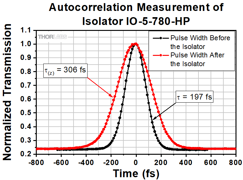
Pulse Dispersion
Pulse broadening occurs anytime a pulse propagates through a material with an index of refraction greater than 1. This dispersion increases inversely with the pulse width and therefore can become significant in ultrafast lasers.
τ: Pulse Width Before Isolator
τ(z): Pulse Width After Isolator
Example:
τ = 197 fs results in τ(z) = 306 fs (pictured in Figure 54D)
τ = 120 fs results in τ(z) = 186 fs
Click to Enlarge
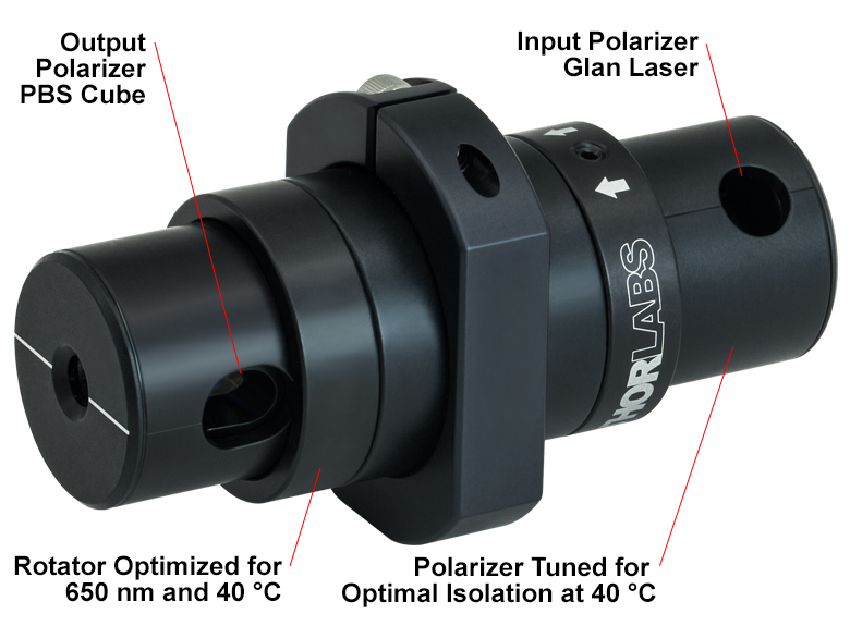
Figure 32A Custom Isolator Example
Custom Adjustable Narrowband Isolator with Different Input and Output Polarizers Optimized for 650 nm Wavelength and 40 °C Temperature.
OEM Application Services
- Direct Integration to Laser Head Assemblies
- Combination Isolator and Fiber Coupling Units
- Minimum Footprint Packages
- Filter Integration
- Active Temperature Control and Monitoring
- Feedback Monitoring
- Environmental Qualification
- Private Labeling
- ITAR-Compliant Assembly
OEM and Non-Standard Isolators
In an effort to provide the best possible service to our customers, Thorlabs has made a commitment to ship our most popular free-space and fiber isolator models from stock. We currently offer same-day shipping on more than 90 isolator models. In addition to these stock models, non-stock isolators with differing aperture sizes, wavelength ranges, package sizes, and polarizers are available. In addition, we can create isolators tuned for specific operating temperatures and isolators that incorporate thermistors with heating or cooling elements for active temperature control and monitoring. These generally have the same price as a similar stock unit. If you would like a quote on a non-stock isolator, please fill out the form below and a member of our staff will be in contact with you.
Thorlabs has many years of experience working with OEM, government, and research customers, allowing us to tailor your isolator to specific design requirements. In addition to customizing our isolators (see the OEM Application Services list), we also offer various application services.
| Table 32B Specifications | |
|---|---|
| Parameter | Range |
| Wavelength Range | From 365 - 4550 nma |
| Aperture Sizes | Up to Ø15 mm |
| Polarization Dependence | Dependent or Independent |
| Max Powerb | Up to 2 GW/cm² |
| Isolation | Up to 60 dB (Tandem Units) |
| Operating Temperature | 10 - 70 °C |
Free-Space Isolators
We are able to provide a wide range of flexibility in manufacturing non-stock, free-space isolators. Almost any selection of specifications from our standard product line can be combined to suit a particular need. Table 32B shows the range of specifications that we can meet.
We offer isolators suitable for both narrowband and broadband applications. The size of the housing is very dependent on the desired maximum power and aperture size, so please include a note in the quote form below if you have special requirements.
Faraday Rotators
We offer Faraday rotators center wavelengths from 532 nm to 1550 nm. These are the same components used to make our isolators and rotate the polarization of incoming light by 45°. Please contact Tech Support if you require a Faraday rotator with a rotation angle or center wavelength outside of the aforementioned specifications.
| Table 32C Specifications | |
|---|---|
| Parameter | Range |
| Wavelength Range | From 633 - 2050 nma |
| Polarization Dependence | Dependent or Independent |
| Max Powerb (Fiber to Free-Space) | 30 W |
| Max Powerb (Fiber to Fiber) | 20 W |
| Operating Temperature | 10 - 70 °C |
Fiber Isolators
Thorlabs is uniquely positioned to draw on experience in classical optics, fiber coupling, and isolators to provide flexible designs for a wide range of fiber optic specifications. Current design efforts are focused on increasing the Maximum power of our fiber isolators at and near the 1064 nm wavelength. We offer models with integrated ASE filters and taps. Table 32C highlights the range of specifications that we can meet.
The fiber used is often the limiting factor in determining the Maximum power the isolator can handle. We have experience working with single mode (SM) and polarization-maintaining fibers (PM); single-, double- and triple-clad fibers; and specialty fibers like 10-to-30 µm LMA fibers and PM LMA fibers. For more information about the fiber options available with our custom isolators, please see Tables 32D and 32E.
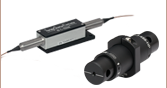
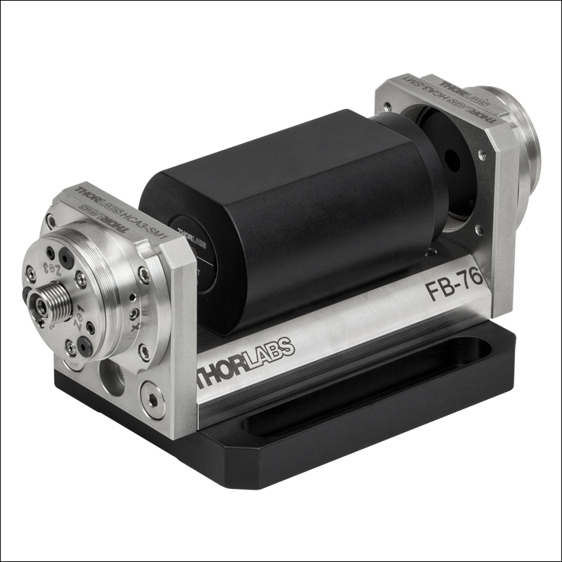
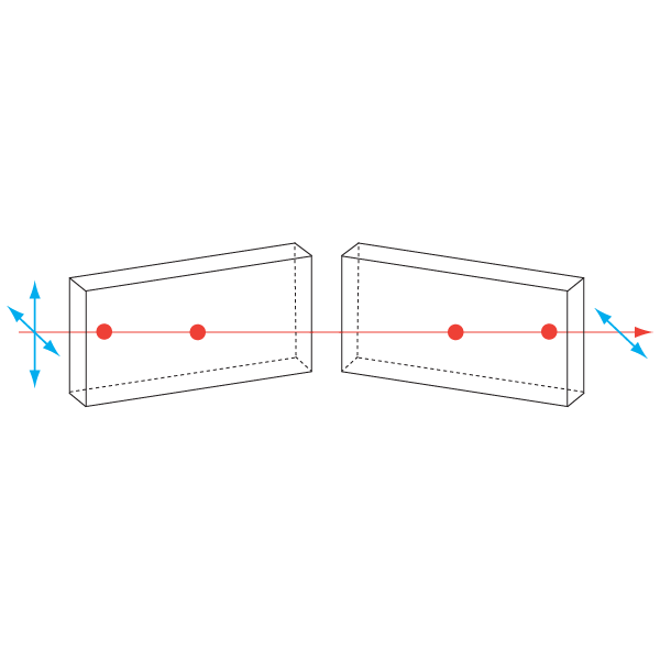
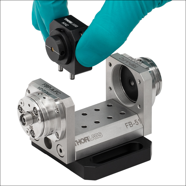
In the spectral region below 633 nm, we recommend mounting one of our free-space isolators in a FiberBench system. A FiberBench system consists of pre-designed modules that make it easy to use free-space optical elements with a fiber optic system while maintaining excellent coupling efficiency. Upon request, we can provide select stock isolators in an optic mount with twin steel dowel pins for our FiberBench systems, as shown to the left.
We are also in the process of extending our fiber isolator capabilities down into the visible region. For more information, please contact Technical Support.
Custom Fiber Isolator

Custom Free-Space Isolator for Wavelengths Below 633 nm
Click to Enlarge
Twin Steel Pins Insert into FiberBench

Click to Enlarge
Mounted Isolator
| Table 32D Polarization Independent Fiber |
|---|
| Table 32E Polarization Maintaining Fiber |
|---|
Make to Order Options
Tables 32F, 32G, 32H, and 32J provide information on some common isolator and rotator specials we have manufactured in the past. We keep the majority of the components for these custom isolators in stock to ensure quick builds, so these specials are available with an average lead time of only 2-4 weeks. Please use the Non-Stock Isolator Worksheet below for a quote.
| Table 32F Adjustable Narrowband Isolators |
|---|
| Table 32G Faraday Rotators |
|---|
| Table 32H Fixed Narrowband Isolators |
|---|
| Table 32J Fixed Broadband Isolators |
|---|
Custom Request Form
Request a custom isolator quote using the form below or by contacting us for more information at (973) 300-3000.
| Posted Comments: | |
P. Kucirek
(posted 2023-01-09 17:51:58.933) Hi,
do you have any data on the maximum permissible power density for pulsed operation for the IO-4-2050-VLP ? PRF ~100 Hz, duration 500 ns
Best regards eric lallier
(posted 2022-02-14 05:44:47.51) IO-4-2050-HP:
1) I don't understand how the 25 W and 250 W/cm2 are compatible unless the beam is top hat and fills the 3.8 mm diameter. For a gaussian beam with 99% energy in this diameter, I find a max waist radius of 1.2 mm and a power density of 1.1 kW/cm2 for 25 W (beam area = Pi/2*w0^2). Is the 250 W/cm2 value right ?
2) Which is the weakest element, the Faraday crystal or the polarizers ?
3) What is the pulsed damage threshold ? jdelia
(posted 2022-03-03 10:19:58.0) Thank you for contacting Thorlabs. These isolators are based on a flat top full aperture. A 3.8 mm maximum beam diameter corresponds to around .113 cm^2. Multiplying that by 250 W/cm^2 gives you around 25 W. We expect the polarizers to be the weaker elements between those and the crystal. Lastly, we unfortunately do not have pulsed damage threshold data on these isolators, but we may test for this in the future. I have contacted you directly regarding the specifications of your beam. bbramman
(posted 2018-02-09 14:42:19.53) Hello,
Will this 1150nm Isolator suffice for an 1107nm laser, or do we need to custom make a different isolator?
Thanks,
Brendan tfrisch
(posted 2018-03-22 03:08:49.0) Hello, thank you for contacting Thorlabs. We list the expected isolation and peak transmission as about 25dB and 90% for IO-4-1150-VLP at 1110nm. I will reach out to you about whether this is suitable or whether you would need a custom. yisun7
(posted 2017-06-29 11:36:08.75) Could you send me a quote with same parameter as IO-5-1480-I, Faraday rotator only? Some how I fail to submit it in "custom isolator" tab. nbayconich
(posted 2017-06-30 09:24:09.0) Thank you for contacting Thorlabs. I will reach out to you directly with a quote for the faraday rotator. tcohen
(posted 2012-07-17 10:14:00.0) Response from Tim at Thorlabs: Thank you for contacting us. Our stock isolators are aligned such that they come in at 0 degrees and rotate to 45 degrees with respect to the housing. In this case, I can understand that the symmetry has caused ambiguity. Please ensure that your light is incident on the black input polarizer. If used in reverse the faraday element will rotate the light to 90 degrees with respect to the black polarizer and will be blocked. jikim
(posted 2012-07-16 14:47:29.0) It is the question about the small isolator, IO-D-1550-VLP. jikim
(posted 2012-07-16 14:45:40.0) How can I distinguish the input and the output port? |
The following selection guide contains all of Thorlabs' Free-Space Optical Isolators. Click the colored bars below to to see specifications and options for each wavelength range and isolator type. Please note that Thorlabs also offers fiber optical isolators and custom optical isolators.
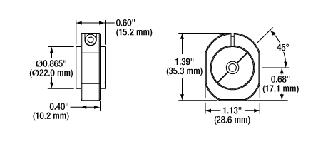
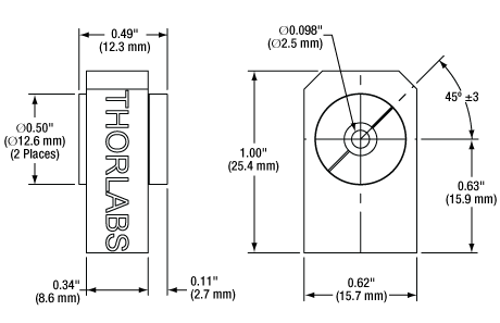
IO-4-1150-VLP Simplified Mechanical Drawing
| Click Image for Details | 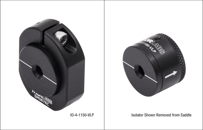 |
| Item # | IO-4-1150-VLPa |
| Type | Adjustable Narrowband |
| Polarizer Typeb | Very Low Power (VLP) |
| Center Wavelength | 1150 nm |
| Tuning Range | 1120 - 1180 nm |
| Operating Range | 1110 - 1190 nm |
| Transmissionc | 91% |
| Isolationc | 38 dB (Min) |
| Performance Graph (Click for Details) |
 |
| Max Beam Diameterd | 3.6 mm |
| Max Powere | 1.2 W |
| Max Power Density | Blocking:f 25 W/cm2 Transmission:f 100 W/cm2 |
| Compatible Mounting Adaptersg |
H1C SM1B2 SM087RCh (SM087RC/M) |
IO-4-1220-VLP Simplified Mechanical Drawing
| Click Image for Details | 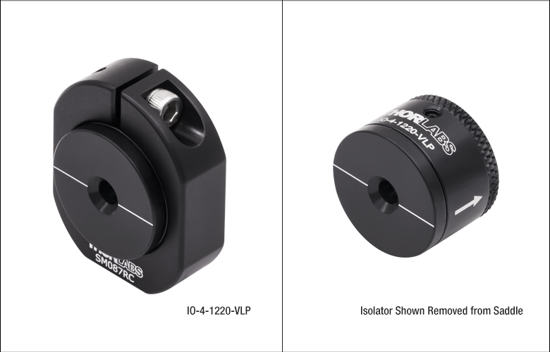 |
| Item # | IO-4-1220-VLPa |
| Type | Adjustable Narrowband |
| Polarizer Typeb | Very Low Power (VLP) |
| Center Wavelength | 1220 nm |
| Tuning Range | 1190 - 1250 nm |
| Operating Range | 1180 - 1260 nm |
| Transmissionc | 93% |
| Isolationc | 38 dB (Min) |
| Performance Graph (Click for Details) |
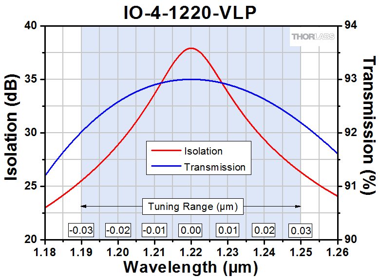 |
| Max Beam Diameterd | 3.6 mm |
| Max Powere | 1.2 W |
| Max Power Density | Blocking:f 25 W/cm2 Transmission:f 100 W/cm2 |
| Compatible Mounting Adaptersg |
H1C SM1B2 SM087RCh (SM087RC/M) |

Click for Details
IO-2.5-1310-VLP
Simplified Mechanical Drawing
The mounting saddle contains an 8-32 tap. For an M4-threaded saddle, please contact Tech Support prior to ordering.
| Click Image for Details | 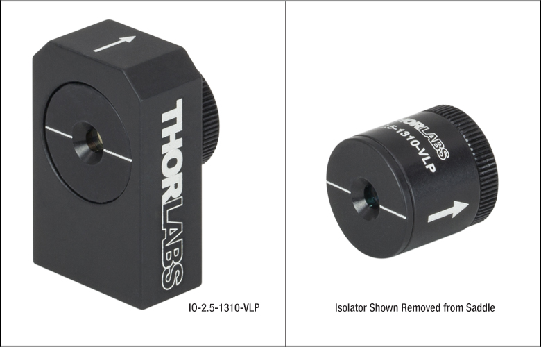 |
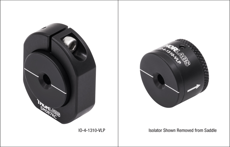 |
| Item # | IO-2.5-1310-VLPa,b | IO-4-1310-VLPa |
| Type | Fixed Narrowband | Adjustable Narrowband |
| Polarizer Typec | Very Low Power (VLP) | |
| Center Wavelength | 1310 nm | 1310 nm |
| Tuning Range | N/A | 1275 - 1350 nm |
| Operating Range | 1250 - 1375 nm | 1250 - 1375 nm |
| Transmissiond | 95% | 95% |
| Isolationd | 38 dB (Min) 43 dB (Typ.) |
38 dB (Min) 42 dB (Typ.) |
| Performance Graph (Click for Details) |
 |
 |
| Max Beam Diametere | 2.3 mm | 3.6 mm |
| Max Powerf | 0.4 W | 1.2 W |
| Max Power Density | Blocking:g 25 W/cm2 Transmission:g 100 W/cm2 |
Blocking:g 25 W/cm2 Transmission:g 100 W/cm2 |
| Compatible Mounting Adaptersh |
N/A | H1C SM1B2 SM087RCi (SM087RC/M) |
IO-4-1390-VLP Simplified Mechanical Drawing
| Click Image for Details | 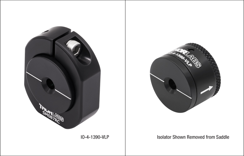 |
| Item # | IO-4-1390-VLPa |
| Type | Adjustable Narrowband |
| Polarizer Typeb | Very Low Power (VLP) |
| Center Wavelength | 1390 nm |
| Tuning Range | 1350 - 1430 nm |
| Operating Range | 1340 - 1440 nm |
| Transmissionc | 93% |
| Isolationc | 35 dB (Min) |
| Performance Graph (Click for Details) |
 |
| Max Beam Diameterd | 3.6 mm |
| Max Powere | 1.2 W |
| Max Power Density | Blocking:f 25 W/cm2 Transmission:f100 W/cm2 |
| Compatible Mounting Adaptersg |
H1C SM1B2 SM087RCh (SM087RC/M) |
IO-4-1480-VLP Simplified Mechanical Drawing
| Click Image for Details | 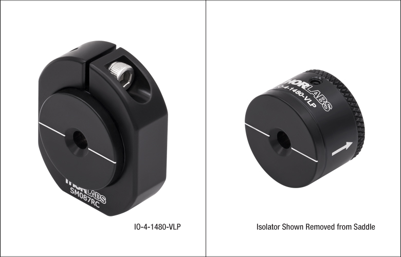 |
| Item # | IO-4-1480-VLPa |
| Type | Adjustable Narrowband |
| Polarier Typeb | Very Low Power (VLP) |
| Center Wavelength | 1480 nm |
| Tuning Range | 1440 - 1520 nm |
| Operating Range | 1430 - 1530 nm |
| Transmissionc | 93% |
| Isolationc | 38 dB (Min) |
| Performance Graph (Click for Details) |
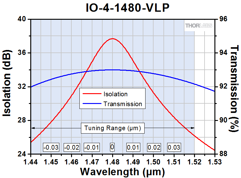 |
| Max Beam Diameterd | 3.6 mm |
| Max Powere | 1.2 W |
| Max Power Density | Blocking:f 25 W/cm2 Transmission:f 100 W/cm2 |
| Compatible Mounting Adaptersg |
H1C SM1B2 SM087RCh (SM087RC/M) |
| Click Image for Details | 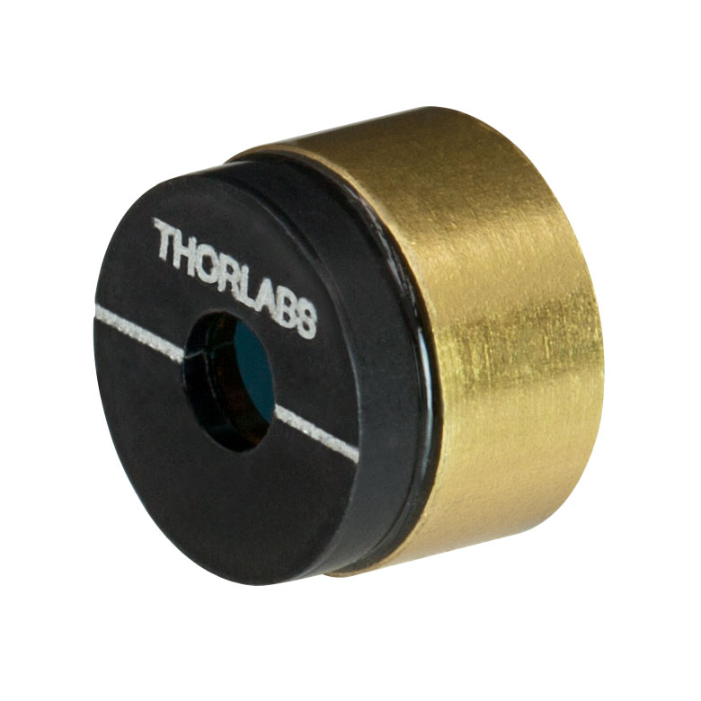 |
 |
 |
 |
 |
 |
| Item # | IO-D-1550-VLPa,b | IO-2.5-1550-VLPb,c | IO-2.5-1550-HPc,d | IO-4-1550-VLPb | IOT-4-1550-VLP | IO-5-1550-HPd |
| Type | Fixed Narrowband | Fixed Narrowband | Adjustable Narrowband | Adjustable Narrowband | Tandem Fixed Narrowband | Adjustable Narrowband |
| Polarizer Typee | Very Low Power (VLP) | Very Low Power (VLP) | High Power (HP) | Very Low Power (VLP) | Very Low Power (VLP) | High Power (HP) |
| Center Wavelength | 1550 nm | 1550 nm | 1550 nm | 1550 nm | 1550 nm | 1550 nm |
| Tuning Range | N/A | N/A | 1510 - 1590 nm | 1510 - 1590 nm | N/A | 1510 - 1590 nm |
| Operating Range | 1500 - 1600 nm | 1500 - 1600 nm | 1500 - 1600 nm | 1500 - 1600 nm | 1500 - 1600 nm | 1500 - 1600 nm |
| Transmissionf | 95% | 95% | 92% | 95% | 85% | 92% |
| Isolationf | 36 dB (Min) 40 dB (Typ.) |
38 dB (Min) 43 dB (Typ.) |
38 dB (Min) 42 dB (Typ.) |
38 dB (Min) 42 dB (Typ.) |
60 dB (Min) | 38 dB (Min) 42 dB (Typ.) |
| Performance Graph (Click for Details) |
 |
 |
 |
 |
 |
 |
| Max Beam Diameterg | 1.6 mm | 2.3 mm | 2.3 mm | 3.6 mm | 3.6 mm | 4.7 mm |
| Max Powerh | 0.2 W | 0.4 W | 4 W | 1.2 W | 2.4 W | 15 W |
| Max Power Density | Blocking:i 25 W/cm2 Transmission:i 100 W/cm2 |
Blocking:i 25 W/cm2 Transmission:i 100 W/cm2 |
250 W/cm2 | Blocking:i 25 W/cm2 Transmission:i 100 W/cm2 |
Blocking: 50 W/cm2 | 250 W/cm2 |
| Compatible Mounting Adaptersj |
N/A | H1C SM1B2 SM087RCk (SM087RC/M) |
CP36 SM1RCl (SM1RC/M) SM1TC SM2A21 |
|||
IO-4-1650-VLP Simplified Mechanical Drawing
| Click Image for Details | 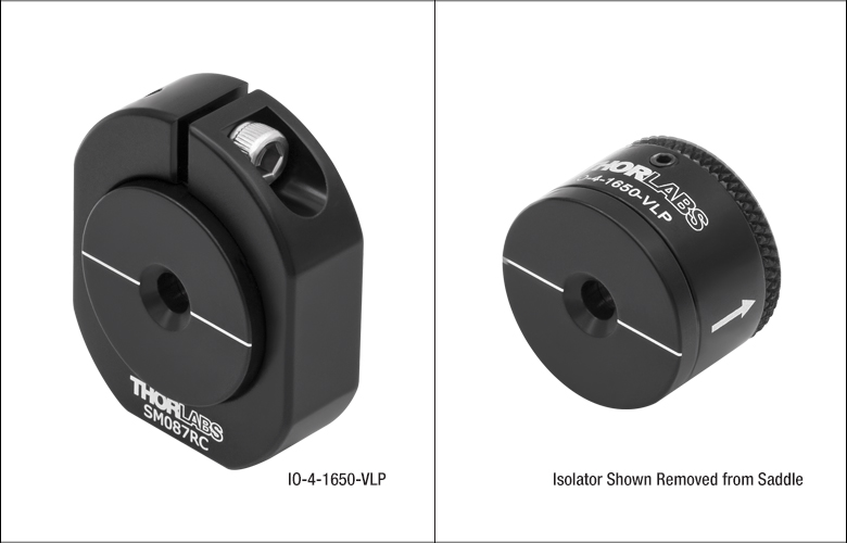 |
| Item # | IO-4-1650-VLPa |
| Type | Adjustable Narrowband |
| Polarizer Typeb | Very Low Power (VLP) |
| Center Wavelength | 1650 nm |
| Tuning Range | 1610 - 1690 nm |
| Operating Range | 1600 - 1700 nm |
| Transmissionc | 93% |
| Isolationc | 38 dB (Min) |
| Performance Graph (Click for Details) |
 |
| Max Beam Diameterd | 3.6 mm |
| Max Powere | 1.2 W |
| Max Power Density | Blocking:f 25 W/cm2 Transmission:f 100 W/cm2 |
| Compatible Mounting Adaptersg |
H1C SM1B2 SM087RCh (SM087RC/M) |

I1750P4 Simplified Mechanical Drawing
| Click Image for Details | 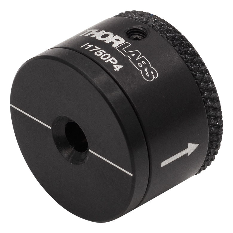 |
| Item # | I1750P4 |
| Type | Adjustable Narrowband |
| Polarizer Typea | Very Low Power (P) |
| Center Wavelength | 1750 nm |
| Tuning Range | 1710 - 1790 nm |
| Operating Range | 1700 - 1800 nm |
| Transmissionb | 90% (Min) |
| Isolationb | 30 dB (Min) 33 dB (Typ.) |
| Performance Graph (Click for Details) |
 |
| Max Beam Diameterc | 3.6 mm |
| Max Powerd | 1.2 W |
| Max Power Density | Blocking:e 25 W/cm2 Transmission:e 100 W/cm2 |
| Compatible Mounting Adaptersf |
H1C SM1B2 SM087RC (SM087RC/M) |

I1850P4 Simplified Mechanical Drawing
| Click Image for Details | 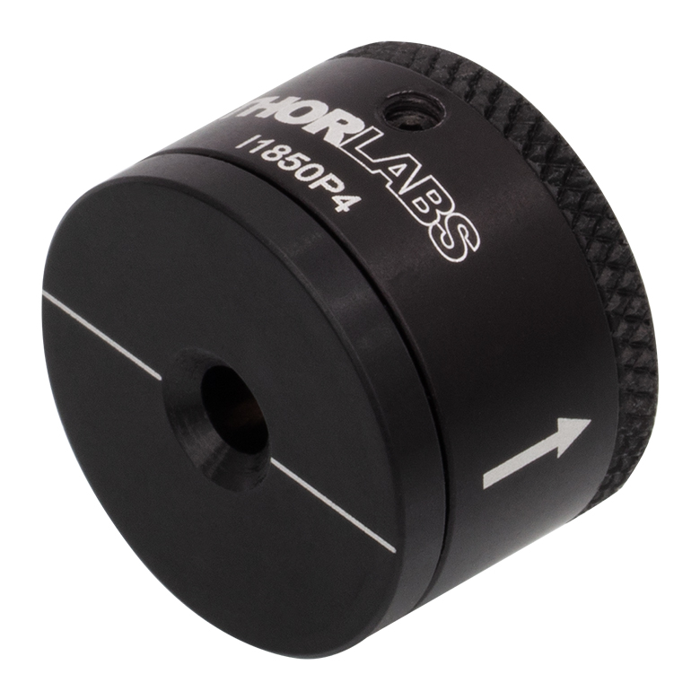 |
| Item # | I1850P4 |
| Type | Adjustable Narrowband |
| Polarizer Typea | Very Low Power (P) |
| Center Wavelength | 1850 nm |
| Tuning Range | 1810 - 1890 nm |
| Operating Range | 1800 - 1900 nm |
| Transmissionb | 90% (Min) |
| Isolationb | 30 dB (Min) 33 dB (Typ.) |
| Performance Graph (Click for Details) |
 |
| Max Beam Diameterc | 3.6 mm |
| Max Powerd | 1.2 W |
| Max Power Density | Blocking:e 25 W/cm2 Transmission:e 100 W/cm2 |
| Compatible Mounting Adaptersf |
H1C SM1B2 SM087RC (SM087RC/M) |
I1950P4 Simplified Mechanical Drawing
| Click Image for Details |  |
| Item # | I1950P4 |
| Type | Adjustable Narrowband |
| Polarizer Typea | Very Low Power (P) |
| Center Wavelength | 1950 nm |
| Tuning Range | 1910 - 1990 nm |
| Operating Range | 1900 - 2000 nm |
| Transmissionb | 90% (min) |
| Isolationb | 30 dB (Min) 33 dB (Typ.) |
| Performance Graph (Click for Details) |
 |
| Max Beam Diameterc | 3.6 mm |
| Max Powerd | 1.2 W |
| Max Power Density | Blocking:e 25 W/cm2 Transmission:e 100 W/cm2 |
| Compatible Mounting Adaptersf |
H1C SM1B2 SM087RC (SM087RC/M) |
| Click Image for Details | 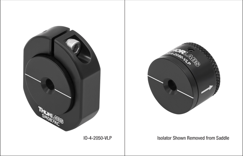 |
 |
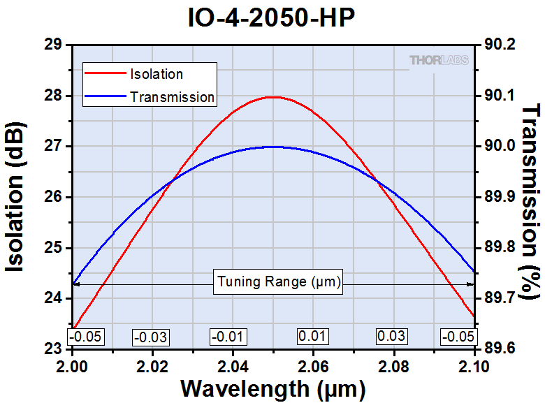
| Item # | IO-4-2050-VLPa | IO-4-2050-HPb |
| Type | Adjustable Narrowband | Adjustable Narrowband |
| Polarizer Typec | Very Low Power (VLP) | High Power (HP) |
| Center Wavelength | 2050 nm | 2050 nm |
| Tuning Range | 2000 - 2100 nm | 2000 - 2100 nm |
| Operating Range | 2000 - 2100 nm | 2000 - 2100 nm |
| Transmissiond | 85% | 90% |
| Isolationd | 28 dB (Min) 33 dB (Typ.) |
28 dB (Min) 33 dB (Typ.) |
| Performance Graph (Click for Details) |
 |
 |
| Max Beam Diametere | 3.6 mm | 3.8 mm |
| Max Powerf | 1.2 W | 25 W |
| Max Power Density | Blockingg: 25 W/cm2 Transmissiong: 100 W/cm2 |
250 W/cm2 |
| Compatible Mounting Adaptersh |
H1C SM1B2 SM087RCi (SM087RC/M) |
CP36 SM1RCj (SM1RC/M) SM1TC SM2A21 |
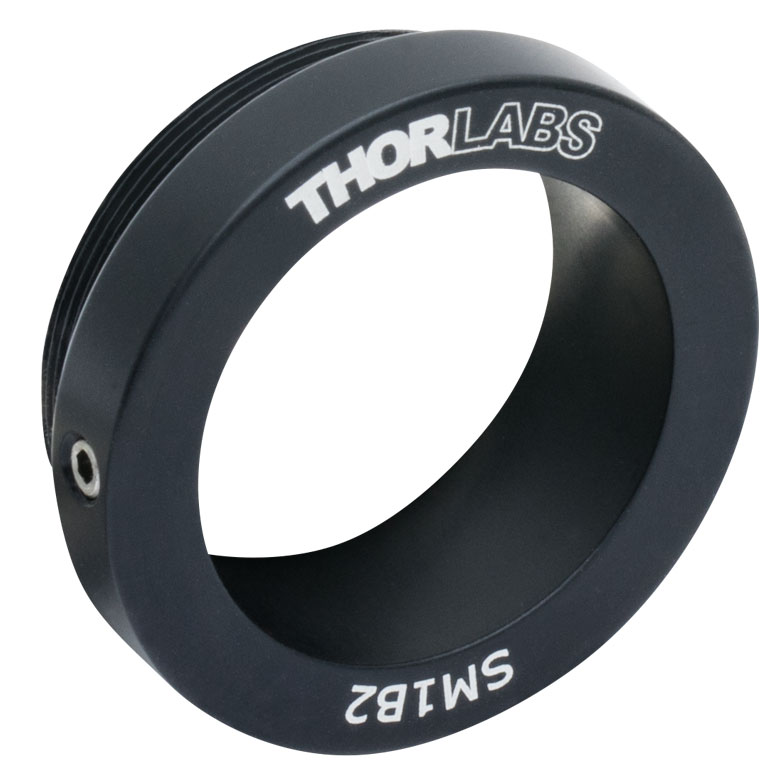
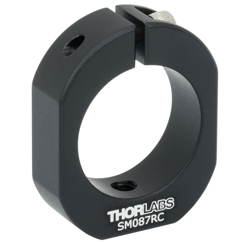
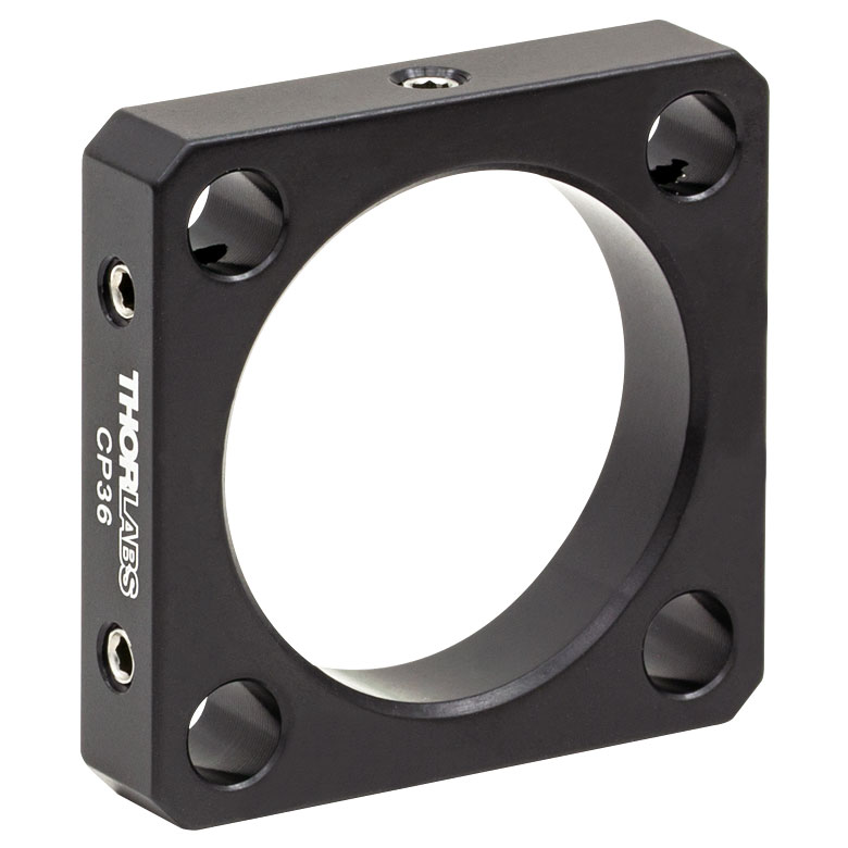
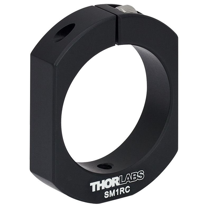
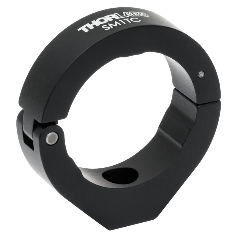
These adapters provide mechanical compatibility between our isolator bodies and SM1 (1.035"-40) lens tubes, SM2 (2.035"-40) lens tubes, 30 mm cage systems, Ø1/2" posts, and our FiberBench systems.
| Click Image to Enlarge | 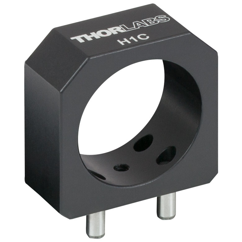 |
 |
 |
 |
 |
 |
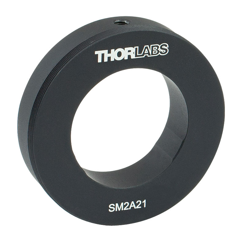 |
| Item # | H1C | SM1B2 | SM087RC(/M) | CP36 | SM1RC(/M) | SM1TC | SM2A21 |
| Isolator Diameter | 0.865" | 0.865" | 0.865" | 1.2" | 1.2" | 1.2" | 1.2" |
| Mounting Options | FiberBench Systems | SM1 Lens Tubes | Ø1/2" Posts | 30 mm Cage Systems | Ø1/2" Posts | Ø1/2" Posts | SM2 Lens Tubes or Mechanics with Ø2" Bore |
| Compatible Isolators |
IO-4-1150-VLP
IO-4-1220-VLP IO-4-1310-VLP IO-4-1390-VLP IO-4-1480-VLP IO-4-1550-VLP IOT-4-1550-VLP
IO-4-1650-VLP I1750P4 I1850P4 I1950P4 IO-4-2050-VLP |
IO-5-1550-HP IO-4-2050-HP |
|||||