 Products Home
Fiber-to-Fiber U-Benches
- Fixed or Adjustable Coupling for a Variety of Applications
- Thermally and Mechanically Stable
- Compatible with a Wide Range of FiberBench Accessories
FBP-A-FC
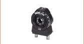
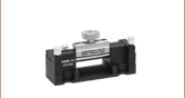
Adjustable U-Bench
with FC Bulkhead for FC/PC and FC/APC Connectors
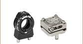
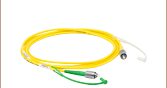
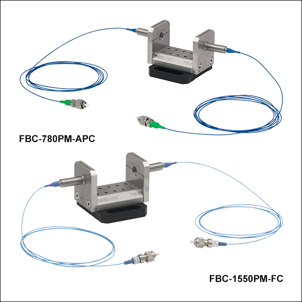
FBC-1550PM-APC
Fixed U-Bench with PM Fiber
and FC/APC Connectors
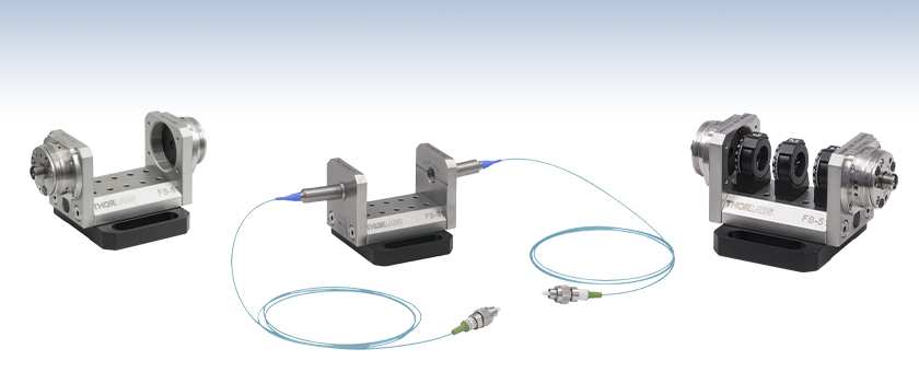
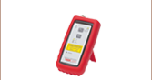
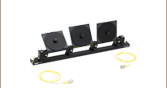
Application Idea
U-Benches Allow the Construction of
Complex Optical Assemblies, Such as our
PC-FFB-1550 Polarization Controller


Please Wait
Click to Enlarge
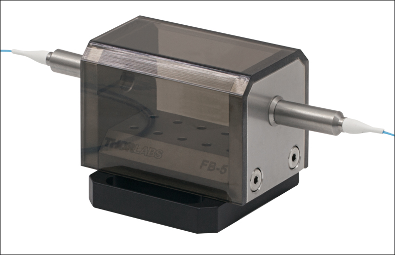
Figure 1.1 Each U-Bench Includes a Removable Plastic Dust Cover

Features
- Fixed U-Benches Available with SM or PM Fiber
- Adjustable U-Benches with FC Bulkhead Compatible with FC/PC and FC/APC Connectors
- Thermally and Mechanically Stable
- Compatible with Thorlabs' Complete Line of FiberBench Components
- Beam Height is 14.3 mm Measured from the Deck
- 303 Non-Magnetic Stainless Steel
- Please Contact Tech Support for Special Wavelengths or Custom-Aligned Kits
Thorlabs' fixed and adjustable fiber-to-fiber U-Benches consist of a FiberBench base combined with either two built-in patch cables or two FiberPorts, respectively. The fixed U-Benches feature factory aligned input and output FC/PC or FC/APC patch cables with a narrowband antireflection coating to minimize insertion and return losses. In contrast, the adjustable U-Benches feature a FiberPort on either end that incorporates an AR-coated aspheric lens for one of three wavelength ranges: 350 - 700 nm
(-A coating), 600 - 1050 nm (-B coating), and 1050 - 1620 nm (-C coating). Please see the Specs tab for more details.
The U-Benches allow for easy access to the optical beam and are ideal for fiber-to-fiber applications that incorporate multiple components and require the utmost in stability. While inserting thick optical components into the beam path, lateral offset can occur leading to additional insertion loss. The XY Tweaker Module can be used to compensate for up to 500 μm of beam displacement. If more space is needed for additional optics in the free-space beam path, we also offer Fiber-to-Fiber Couplers with Adjustable Path Length which can operate with a collimated free-space beam path up to 500 mm long.
| FiberBench Accessories | |||
|---|---|---|---|
| FiberPorts | Optic Mounts | Alignment Tools | Polarizers |
| Beamsplitter Modules | Mirror Modules | Rotating Wave Plates | FiberBenches |
Fixed U-Benches with Single Mode Fiber
| Item # | Connectors | Design Wavelength |
Bandwidth | Fiber | Beam Diameter (1/e2, Typical) |
Insertion Lossa | Return Loss |
|---|---|---|---|---|---|---|---|
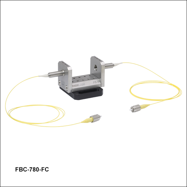
| FBC-780-FC | FC/PC | 780 nm | ±15 nm | 780HP | 0.40 mm | 0.85 ± 0.3 dB | >50 dB |
| FBC-780-APC | FC/APC | ||||||
| FBC-1064-FC | FC/PC | 1064 nm | HI1060 | 0.32 mm | |||
| FBC-1064-APC | FC/APC | ||||||
| FBC-1310-FC | FC/PC | 1310 nm | SMF-28 Ultra | 0.43 mm | 0.6 ± 0.3 dB | ||
| FBC-1310-APC | FC/APC | ||||||
| FBC-1550-FC | FC/PC | 1550 nm | 0.38 mm | ||||
| FBC-1550-APC | FC/APC |
Fixed U-Benches with Polarization-Maintaining Fiber
| Item # | Connectors | Design Wavelength |
Bandwidth | Fiber | Beam Diameter (1/e2, Typical) |
Extinction Ratio |
Insertion Lossa | Return Loss |
|---|---|---|---|---|---|---|---|---|
| FBC-780PM-FC | FC/PC | 780 nm | ±20 nm | PM780-HP | 0.4 mm | ≥16 dB | ≤1.15 dB | ≥50 dB |
| FBC-780PM-APC | FC/APC | |||||||
| FBC-1064PM-FC | FC/PC | 1064 nm | PM980-XP | 0.3 mm | ≥18 dB | |||
| FBC-1064PM-APC | FC/APC | |||||||
| FBC-1310PM-FC | FC/PC | 1310 nm | PM1300-XP | 0.4 mm | ≥19 dB | ≤0.90 dB | ||
| FBC-1310PM-APC | FC/APC | |||||||
| FBC-1550PM-FC | FC/PC | 1550 nm | PM1550-XP | ≥18 dB | ||||
| FBC-1550PM-APC | FC/APC |
Adjustable U-Benches
| Item #a | Compatible Connectors |
EFLb | Input MFDc,d | Output 1/e2 Waist Diameterc |
Max Waist Distancec,e |
Divergencec | Insertion Lossc,f |
Return Lossc,f |
Lens Characteristics | |||
|---|---|---|---|---|---|---|---|---|---|---|---|---|
| CAg | NA | AR Rangeh | Material | |||||||||
| FBP-A-FC | FC/PC and FC/APC | 2.0 mm | 3.5 µm | 0.33 mm | 96 mm | 1.75 mrad | 1.5 dB | >50 dB | 2.0 mm | 0.50 | 350 - 700 nm | ECO-550 |
| FBP-B-FC | FC/PC and FC/APC | 2.0 mm | 5.0 µm | 0.43 mm | 89 mm | 2.50 mrad | 0.85 dB | >50 dB | 2.0 mm | 0.50 | 600 - 1050 nm | ECO-550 |
| FBP-C-FC | FC/PC and FC/APC | 2.0 mm | 10.4 µm | 0.38 mm | 38 mm | 5.20 mrad | 0.6 dB | >50 dB | 2.0 mm | 0.50 | 1050 - 1620 nm | ECO-550 |
| Quick Links |
|---|
| Damage at the Air / Glass Interface |
| Intrinsic Damage Threshold |
| Preparation and Handling of Optical Fibers |
Laser-Induced Damage in Silica Optical Fibers
The following tutorial details damage mechanisms relevant to unterminated (bare) fiber, terminated optical fiber, and other fiber components from laser light sources. These mechanisms include damage that occurs at the air / glass interface (when free-space coupling or when using connectors) and in the optical fiber itself. A fiber component, such as a bare fiber, patch cable, or fused coupler, may have multiple potential avenues for damage (e.g., connectors, fiber end faces, and the device itself). The maximum power that a fiber can handle will always be limited by the lowest limit of any of these damage mechanisms.
While the damage threshold can be estimated using scaling relations and general rules, absolute damage thresholds in optical fibers are very application dependent and user specific. Users can use this guide to estimate a safe power level that minimizes the risk of damage. Following all appropriate preparation and handling guidelines, users should be able to operate a fiber component up to the specified maximum power level; if no maximum is specified for a component, users should abide by the "practical safe level" described below for safe operation of the component. Factors that can reduce power handling and cause damage to a fiber component include, but are not limited to, misalignment during fiber coupling, contamination of the fiber end face, or imperfections in the fiber itself. For further discussion about an optical fiber’s power handling abilities for a specific application, please contact Thorlabs’ Tech Support.
Damage at the Air / Glass Interface
There are several potential damage mechanisms that can occur at the air / glass interface. Light is incident on this interface when free-space coupling or when two fibers are mated using optical connectors. High-intensity light can damage the end face leading to reduced power handling and permanent damage to the fiber. For fibers terminated with optical connectors where the connectors are fixed to the fiber ends using epoxy, the heat generated by high-intensity light can burn the epoxy and leave residues on the fiber facet directly in the beam path.
| Table 36C Estimated Optical Power Densities on Air / Glass Interfacea | ||
|---|---|---|
| Type | Theoretical Damage Thresholdb | Practical Safe Levelc |
| CW (Average Power) |
~1 MW/cm2 | ~250 kW/cm2 |
| 10 ns Pulsed (Peak Power) |
~5 GW/cm2 | ~1 GW/cm2 |
Damage Mechanisms on the Bare Fiber End Face
Damage mechanisms on a fiber end face can be modeled similarly to bulk optics, and industry-standard damage thresholds for UV Fused Silica substrates can be applied to silica-based fiber. However, unlike bulk optics, the relevant surface areas and beam diameters involved at the air / glass interface of an optical fiber are very small, particularly for coupling into single mode (SM) fiber. therefore, for a given power density, the power incident on the fiber needs to be lower for a smaller beam diameter.
Table 36C lists two thresholds for optical power densities: a theoretical damage threshold and a "practical safe level". In general, the theoretical damage threshold represents the estimated maximum power density that can be incident on the fiber end face without risking damage with very good fiber end face and coupling conditions. The "practical safe level" power density represents minimal risk of fiber damage. Operating a fiber or component beyond the practical safe level is possible, but users must follow the appropriate handling instructions and verify performance at low powers prior to use.
Calculating the Effective Area for Single Mode Fibers
The effective area for single mode (SM) fiber is defined by the mode field diameter (MFD), which is the cross-sectional area through which light propagates in the fiber; this area includes the fiber core and also a portion of the cladding. To achieve good efficiency when coupling into a single mode fiber, the diameter of the input beam must match the MFD of the fiber.
As an example, SM400 single mode fiber has a mode field diameter (MFD) of ~Ø3 µm operating at 400 nm, while the MFD for SMF-28 Ultra single mode fiber operating at 1550 nm is Ø10.5 µm. The effective area for these fibers can be calculated as follows:
SM400 Fiber: Area = Pi x (MFD/2)2 = Pi x (1.5 µm)2 = 7.07 µm2 = 7.07 x 10⁻⁸ cm2
SMF-28 Ultra Fiber: Area = Pi x (MFD/2)2 = Pi x (5.25 µm)2 = 86.6 µm2 = 8.66 x 10⁻⁷ cm2
To estimate the power level that a fiber facet can handle, the power density is multiplied by the effective area. Please note that this calculation assumes a uniform intensity profile, but most laser beams exhibit a Gaussian-like shape within single mode fiber, resulting in a higher power density at the center of the beam compared to the edges. Therefore, these calculations will slightly overestimate the power corresponding to the damage threshold or the practical safe level. Using the estimated power densities assuming a CW light source, we can determine the corresponding power levels as:
SM400 Fiber: 7.07 x 10⁻⁸ cm2 x 1 MW/cm2 = 7.1 x 10⁻⁸ MW = 71 mW (Theoretical Damage Threshold)
7.07 x 10⁻⁸ cm2 x 250 kW/cm2 = 1.8 x 10⁻⁵ kW = 18 mW (Practical Safe Level)
SMF-28 Ultra Fiber: 8.66 x 10⁻⁷ cm2 x 1 MW/cm2 = 8.7 x 10⁻⁷ MW = 870 mW (Theoretical Damage Threshold)
8.66 x 10⁻⁷ cm2 x 250 kW/cm2 = 2.1 x 10⁻⁴ kW = 210 mW (Practical Safe Level)
Effective Area of Multimode Fibers
The effective area of a multimode (MM) fiber is defined by the core diameter, which is typically far larger than the MFD of an SM fiber. For optimal coupling, Thorlabs recommends focusing a beam to a spot roughly 70 - 80% of the core diameter. The larger effective area of MM fibers lowers the power density on the fiber end face, allowing higher optical powers (typically on the order of kilowatts) to be coupled into multimode fiber without damage.
Damage Mechanisms Related to Ferrule / Connector Termination
 Click to Enlarge
Figure 36D Plot showing approximate input power that can be incident on a single mode silica optical fiber with a termination. Each line shows the estimated power level due to a specific damage mechanism. The maximum power handling is limited by the lowest power level from all relevant damage mechanisms (indicated by a solid line).
Fibers terminated with optical connectors have additional power handling considerations. Fiber is typically terminated using epoxy to bond the fiber to a ceramic or steel ferrule. When light is coupled into the fiber through a connector, light that does not enter the core and propagate down the fiber is scattered into the outer layers of the fiber, into the ferrule, and the epoxy used to hold the fiber in the ferrule. If the light is intense enough, it can burn the epoxy, causing it to vaporize and deposit a residue on the face of the connector. This results in localized absorption sites on the fiber end face that reduce coupling efficiency and increase scattering, causing further damage.
For several reasons, epoxy-related damage is dependent on the wavelength. In general, light scatters more strongly at short wavelengths than at longer wavelengths. Misalignment when coupling is also more likely due to the small MFD of short-wavelength SM fiber that also produces more scattered light.
To minimize the risk of burning the epoxy, fiber connectors can be constructed to have an epoxy-free air gap between the optical fiber and ferrule near the fiber end face. Our high-power multimode fiber patch cables use connectors with this design feature.
Determining Power Handling with Multiple Damage Mechanisms
When fiber cables or components have multiple avenues for damage (e.g., fiber patch cables), the maximum power handling is always limited by the lowest damage threshold that is relevant to the fiber component. In general, this represents the highest input power that can be incident on the patch cable end face and not the coupled output power.
As an illustrative example, Figure 36D shows an estimate of the power handling limitations of a single mode fiber patch cable due to damage to the fiber end face and damage via an optical connector. The total input power handling of a terminated fiber at a given wavelength is limited by the lower of the two limitations at any given wavelength (indicated by the solid lines). A single mode fiber operating at around 488 nm is primarily limited by damage to the fiber end face (blue solid line), but fibers operating at 1550 nm are limited by damage to the optical connector (red solid line).
In the case of a multimode fiber, the effective mode area is defined by the core diameter, which is larger than the effective mode area for SM fiber. This results in a lower power density on the fiber end face and allows higher optical powers (on the order of kilowatts) to be coupled into the fiber without damage (not shown in graph). However, the damage limit of the ferrule / connector termination remains unchanged and as a result, the maximum power handling for a multimode fiber is limited by the ferrule and connector termination.
Please note that these are rough estimates of power levels where damage is very unlikely with proper handling and alignment procedures. It is worth noting that optical fibers are frequently used at power levels above those described here. However, these applications typically require expert users and testing at lower powers first to minimize risk of damage. Even still, optical fiber components should be considered a consumable lab supply if used at high power levels.
Intrinsic Damage Threshold
In addition to damage mechanisms at the air / glass interface, optical fibers also display power handling limitations due to damage mechanisms within the optical fiber itself. These limitations will affect all fiber components as they are intrinsic to the fiber itself. Two categories of damage within the fiber are damage from bend losses and damage from photodarkening.
Bend Losses
Bend losses occur when a fiber is bent to a point where light traveling in the core is incident on the core/cladding interface at an angle higher than the critical angle, making total internal reflection impossible. Under these circumstances, light escapes the fiber, often in a localized area. The light escaping the fiber typically has a high power density, which burns the fiber coating as well as any surrounding furcation tubing.
A special category of optical fiber, called double-clad fiber, can reduce the risk of bend-loss damage by allowing the fiber’s cladding (2nd layer) to also function as a waveguide in addition to the core. By making the critical angle of the cladding/coating interface higher than the critical angle of the core/clad interface, light that escapes the core is loosely confined within the cladding. It will then leak out over a distance of centimeters or meters instead of at one localized spot within the fiber, minimizing the risk of damage. Thorlabs manufactures and sells 0.22 NA double-clad multimode fiber, which boasts very high, megawatt range power handling.
Photodarkening
A second damage mechanism, called photodarkening or solarization, can occur in fibers used with ultraviolet or short-wavelength visible light, particularly those with germanium-doped cores. Fibers used at these wavelengths will experience increased attenuation over time. The mechanism that causes photodarkening is largely unknown, but several fiber designs have been developed to mitigate it. For example, fibers with a very low hydroxyl ion (OH) content have been found to resist photodarkening and using other dopants, such as fluorine, can also reduce photodarkening.
Even with the above strategies in place, all fibers eventually experience photodarkening when used with UV or short-wavelength light, and thus, fibers used at these wavelengths should be considered consumables.
Preparation and Handling of Optical Fibers
General Cleaning and Operation Guidelines
These general cleaning and operation guidelines are recommended for all fiber optic products. Users should still follow specific guidelines for an individual product as outlined in the support documentation or manual. Damage threshold calculations only apply when all appropriate cleaning and handling procedures are followed.
-
All light sources should be turned off prior to installing or integrating optical fibers (terminated or bare). This ensures that focused beams of light are not incident on fragile parts of the connector or fiber, which can possibly cause damage.
-
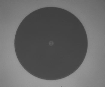
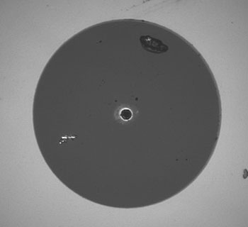
The power-handling capability of an optical fiber is directly linked to the quality of the fiber/connector end face. Always inspect the fiber end prior to connecting the fiber to an optical system. The fiber end face should be clean and clear of dirt and other contaminants that can cause scattering of coupled light. Bare fiber should be cleaved prior to use and users should inspect the fiber end to ensure a good quality cleave is achieved.
-
If an optical fiber is to be spliced into the optical system, users should first verify that the splice is of good quality at a low optical power prior to high-power use. Poor splice quality may increase light scattering at the splice interface, which can be a source of fiber damage.
-
Users should use low power when aligning the system and optimizing coupling; this minimizes exposure of other parts of the fiber (other than the core) to light. Damage from scattered light can occur if a high power beam is focused on the cladding, coating, or connector.
Tips for Using Fiber at Higher Optical Power
Optical fibers and fiber components should generally be operated within safe power level limits, but under ideal conditions (very good optical alignment and very clean optical end faces), the power handling of a fiber component may be increased. Users must verify the performance and stability of a fiber component within their system prior to increasing input or output power and follow all necessary safety and operation instructions. The tips below are useful suggestions when considering increasing optical power in an optical fiber or component.
-
Splicing a fiber component into a system using a fiber splicer can increase power handling as it minimizes possibility of air/fiber interface damage. Users should follow all appropriate guidelines to prepare and make a high-quality fiber splice. Poor splices can lead to scattering or regions of highly localized heat at the splice interface that can damage the fiber.
-
After connecting the fiber or component, the system should be tested and aligned using a light source at low power. The system power can be ramped up slowly to the desired output power while periodically verifying all components are properly aligned and that coupling efficiency is not changing with respect to optical launch power.
-
Bend losses that result from sharply bending a fiber can cause light to leak from the fiber in the stressed area. When operating at high power, the localized heating that can occur when a large amount of light escapes a small localized area (the stressed region) can damage the fiber. Avoid disturbing or accidently bending fibers during operation to minimize bend losses.
-
Users should always choose the appropriate optical fiber for a given application. For example, large-mode-area fibers are a good alternative to standard single mode fibers in high-power applications as they provide good beam quality with a larger MFD, decreasing the power density on the air/fiber interface.
-
Step-index silica single mode fibers are normally not used for ultraviolet light or high-peak-power pulsed applications due to the high spatial power densities associated with these applications.
| Posted Comments: | |
That Guy
(posted 2024-02-23 15:25:11.547) Hello Tech Support, I noticed that the FBP adaptable Ubenches have aspheric lenses. Can these also be purchased with achromatic lenses? We sometimes use different wavelengths, that's why.
Also; are there any downsides to using achromatic lenses? cdolbashian
(posted 2024-03-11 02:39:06.0) Thank you for reaching out to us with this inquiry. We can potentially do this for you as a custom. I have contacted you directly to discuss this. Regarding performance, for short focal length lenses, the performance of an asphere is generally better, when compared to an achromat, though notably the achromat performs a bit better under non-monochromatic conditions. Alex Pa
(posted 2023-02-07 01:21:43.46) Hello,
can FBP-C-FC be used to make a delay line by putting on a moving stage one of the fiber ports? If so, what would be the travel range for which the coupling would still be efficient?
Thank you. jgreschler
(posted 2023-02-08 02:30:14.0) Thank you for reaching out to Thorlabs. In it's current iteration the U benches are fixed hardware, so they would not be suitable as a delay line. There are some workarounds for this, I have emailed you directly to discuss possible alternatives. user
(posted 2018-08-16 11:39:44.903) Dear Tech Support,
Where does the 300 mW CW power limitation come from (the connectors, the coupling lenses)?
Best regards
Alop YLohia
(posted 2018-08-16 08:48:14.0) Hello Alop, the 300 mW max power is limited by the connectors. This rating can be increased to 50 W (at 980 nm) with one of our high power SMA cables that can be found here: https://www.thorlabs.com/newgrouppage9.cfm?objectgroup_id=4393. y.gladush
(posted 2017-03-21 08:47:19.687) Hello,
I would like to buy optical bench FBP-C-FC with polarization plate and sample mount. For polarization plate everything is clear - it is FBR-LPNIR. But for sample mount I cannot find appropriate option that fits your U-bench. Ideally it should go with 3d stage. Can you advice me something?
Thank you in advance.
Yuriy tfrisch
(posted 2017-03-30 05:23:13.0) Hello, thank you for contacting Thorlabs. While we don't have a 3-axis translation stage native to our FiberBench system, I will reach out to you directly about some alternatives that could mount a sample. cmar5964
(posted 2016-05-27 20:28:55.247) Could you please comment on what exactly the insertion loss is on the FBA-A-FC? Is it reflection + absorption on both lenses/couplers and assumed coupling efficiency on one side? besembeson
(posted 2016-05-27 04:05:49.0) Response from Bweh at Thorlabs USA: The insertion loss specifications apply to the U bench before additional components are installed. This will change depending on the items that are used with the unit. For minimal IL, we recommend you use anti-reflection coated fibers, and keep core size under 62.6um. basili
(posted 2013-06-20 06:34:48.837) We are interested with adjustable U-Bench FBP-A-FC for fiber to fiber coupling. But we would like to know if it is possible couple optical light from a fiber with 3.0µm/4.3µm core diameter to a standard SMF with 8.2µm/8.9µm and the opposite?. Please let us know asap as want to buy urgently. cdaly
(posted 2013-06-20 14:44:00.0) Response from Chris at Thorlabs: Thank you for using the feedback tool. It's generally not too difficult to couple from a smaller core to a larger core, as since you have the same lens in each fiberport, you are creating a 1:1 image of the first fiber face on the second. Going from larger to smaller is more difficult and will require that you use different focal lengths in order to get good coupling. Even still though your smaller core fiber will need to have a larger numerical aperture in order for this to be possible. yanglifeng
(posted 2013-03-22 23:24:10.76) hi sir/madam:
I want to connect the singlemode fiber with mutimode fiber(the type with 8/125 and 50/125 ),please provide the suitable type for me .thankyou very much. jlow
(posted 2013-03-27 11:35:00.0) Response from Jeremy at Thorlabs: We will contact you directly to start a discussion on the requirements for your application. jlow
(posted 2012-12-24 10:15:00.0) Response from Jeremy at Thorlabs: The FBC-1550-APC is pre-aligned for 1550nm and the typical insertion loss is <0.6dB. There's no adjustment possible with this. I will e-mail you directly to troubleshoot this. qch_sun
(posted 2012-12-19 07:18:48.32) I have used the product FBC-1550-APC,but the insertion loss is more than 1dB, nearly 3dB. Is there any alignment I can do the reduce the loss? jlow
(posted 2012-07-31 17:53:00.0) A response from Jeremy at Thorlabs: Thank you for your inquiry. Yes we would be able to custom align the FBP-A-FC. This would only be a rough alignment and not locked in place. We will get in contact with you directly with regard to a quote. delosrey
(posted 2012-07-26 19:15:52.0) I am interested in this product and this is very useful to my experiment. I just want to ask if it is possible for this U-bench to be pre-aligned at 405nm instead of 633 nm as it was mentioned in this website? bdada
(posted 2011-10-10 17:17:00.0) Response from Buki at Thorlabs:
We will contact you to discuss your application. We do not have a single mode fiber designed for 1200 - 2400nm. SM2000 is from 1700-2100 and SMF28 is from 1260-1620nm. In terms of the optics we can use a D coated lens, which will help with the transmission of the higher wavelengths and should still transmit well over the lower wavelengths, but have increased reflections. assv
(posted 2011-10-06 04:19:23.0) Hi, we need a pigtailed fiber bench for use between 1200 and 2400 nm with a super continuum light source and an OSA covering this range. Can you provide additional specifications for the transmission in this wavelength range? Thorlabs
(posted 2010-08-28 03:28:37.0) Response from Javier at Thorlabs to ziqiangliu: We may be able to quote this pigtailed fiber-fiber coupler for you. I will contact you directly with more details. ziqiangliu
(posted 2010-08-27 22:43:43.0) I need a 1064nm pigtail fiber bench. And I hope the connector will be APC.
Could you give me a quotation for the customerized product?
Best regards,
Jeffery Liu
China-fiber Optics Co., Ltd.
Email: jeffery@china-fiber.net, Ziqiangliu@gmail.com
Cellphone:+86-13632907211 |

 Zoom
Zoom- Aligned at 780 nm, 1064 nm, 1310 nm, or 1550 nm
- Bandwidth: ±15 nm
- FC/PC or FC/APC Connectors (2.0 mm Narrow Key)
Thorlabs' Fixed Fiber-to-Fiber U-Benches allow easy access to the optical beam in a fiber-based application. They facilitate optical chopping and the insertion of plano-plano optical elements such as filters, polarizers, and attenuators, and they are fully compatible with the wide offering of FiberBench components.
Each U-bench includes two 1 meter long FC/PC- or FC/APC-terminated patch cables pre-aligned at each wall plate. For custom versions, please contact Tech Support.
Click to Enlarge
Figure G1.1 Diagram of Fixed U-Bench (Side View)
| Item #a | Connectors | Fiber | Fiber Type |
Design Wavelength |
Insertion Loss |
|---|---|---|---|---|---|
| FBC-780-FC | FC/PC | 780HP | SMb | 780 nm | 0.85 ± 0.3 dB |
| FBC-780-APC | FC/APC | ||||
| FBC-1064-FC | FC/PC | HI1060 | 1064 nm | ||
| FBC-1064-APC | FC/APC | ||||
| FBC-1310-FC | FC/PC | SMF-28 Ultra | 1310 nm | 0.6 ± 0.3 dB | |
| FBC-1310-APC | FC/APC | ||||
| FBC-1550-FC | FC/PC | 1550 nm | |||
| FBC-1550-APC | FC/APC |

 Zoom
Zoom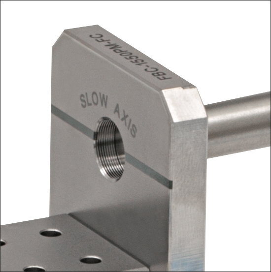
Click to Enlarge
Figure G2.1 A slow axis indicator is engraved on each wall plate.
- Polarization-Maintaining Fiber U-Benches Aligned at 780 nm, 1064 nm, 1310 nm, or 1550 nm
- Bandwidth: ±20 nm
- FC/PC or FC/APC Connectors (2.0 mm Narrow Key)
Thorlabs' Fixed Fiber-to-Fiber U-Benches allow easy access to the optical beam in a fiber-based application. They facilitate optical chopping and the insertion of plano-plano optical elements such as filters, polarizers, and attenuators, and they are fully compatible with the wide offering of FiberBench components.
Each U-bench includes two 1 meter long FC/PC- or FC/APC-terminated patch cables pre-aligned at each wall plate. The patch cable connector keys are aligned to the slow axis. A slow axis indicator for the collimated free-space beam within the U-Bench is engraved in each wall plate, as shown in Figure G2.1. For custom versions of our U-benches, please contact Tech Support.
Click to Enlarge
Figure G2.2 Diagram of Fixed U-Bench (Side View)
| Item #a | Connectors | Fiber | Fiber Type | Design Wavelength |
Insertion Lossb |
|---|---|---|---|---|---|
| FBC-780PM-FC | FC/PC | PM780-HP | PMc | 780 nm | ≤1.15 dB |
| FBC-780PM-APC | FC/APC | ||||
| FBC-1064PM-FC | FC/PC | PM980-XP | 1064 nm | ||
| FBC-1064PM-APC | FC/APC | ||||
| FBC-1310PM-FC | FC/PC | PM1300-XP | 1310 nm | ≤0.90 dB | |
| FBC-1310PM-APC | FC/APC | ||||
| FBC-1550PM-FC | FC/PC | PM1550-XP | 1550 nm | ||
| FBC-1550PM-APC | FC/APC |

 Zoom
Zoom
| Item #a | Compatible Connectors | AR Coating Rangeb | Insertion Lossc |
|---|---|---|---|
| FBP-A-FC | FC/PC and FC/APC | 350 - 700 nm (A Coating) |
1.5 dB |
| FBP-B-FC | FC/PC and FC/APC | 600 - 1050 nm (B Coating) |
0.85 dB |
| FBP-C-FC | FC/PC and FC/APC | 1050 - 1620 nm (C Coating) |
0.6 dB |
- AR Coated for 350 - 700 nm, 600 - 1050 nm, or 1050 - 1620 nm
- Compatible with FC/PC and FC/APC Connectors
- Adjustable Collimation/Coupling for Applications Requiring Flexibility
- Five Degrees of Freedom Plus Rotational Adjustment on Each FiberPort
Figure G3.1 Diagram of Adjustable U-Bench (Side View)
Click to Enlarge
Figure G3.2 Sample -A, -B, and -C AR-Coating Reflectance Curves
Thorlabs' Adjustable Fiber-to-Fiber U-Benches provide the same benefits as the Fixed U-Benches with the added flexibility of two FiberPorts with FC bulkheads. These can be used with any desired fiber patch cables with FC/PC or FC/APC connectors; 2.1 mm wide keys and 2.0 mm narrow keys are compatible. Additionally, each FiberPort allows for adjustable collimation or coupling, if needed. Based on the stable FiberBench platform, these devices are easily configured and aligned for any potential application.
For minimal insertion and return losses, use AR-coated SM, MM, or PM patch cables. For fiber with core size greater than Ø62.5 µm, there will be high insertion loss. At this point, the fiber no longer acts as a point source and the lens is imaging the core rather than creating a collimated beam. Please see the Specs tab for more details. For custom versions, please contact Tech Support.