 Products Home
FiberBench Adjustable Offset Mirror Module

- Intended For Use With Beam Displacer Module
- Compatible with FiberBench Systems
- Protected Silver Mirrors for 450 nm - 20 µm
FBT-P01
Application Idea
Polarization Splitter with
Calcite Beam Displacer and
FBT-P01 Offset Mirror Module


Please Wait
Click to Enlarge
Figure 1.1 Diagram of Polarization Splitter Using
Beam Displacer (Right) and Offset Mirror (Left)
(See Application Tab)

Features
- Protected Silver Coated Offset Mirrors Mounted on Kinematic Base
- Compatible with FiberBenches
- Ravg > 97% from 450 nm - 2 µm; Ravg > 95% from 2 - 20 µm
- ±3° Tip/Tilt Adjustment via Three M2.5 x 0.2 Precision Adjusters
- 360° Continuous Rotation with ±12° Fine Adjustment
- Four Locking Collars and a Spanner Wrench are Included
- Please Contact Tech Support for Other Wavelengths or Custom Requests
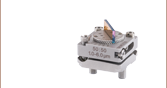
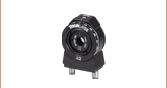
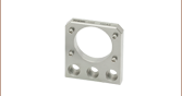
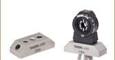
Thorlabs' Offset Mirror Module incorporates two protected silver mirrors mounted on a kinematic base for use in FiberBench systems. The mirrors are positioned off axis from the center beam path such that one of them will intersect the displaced beam from a preceding Beam Displacer Module (walk-off polarizer) and reflect it by 90°, as illustrated in Figure 1.1. Since the undisplaced beam must pass between the mirrors, we recommend choosing a FiberPort with a beam waist diameter <1 mm. Please refer to the Application tab for more details on how to create a polarization splitter by combining a Beam Displacer with an FBT-P01 Offset Mirror.
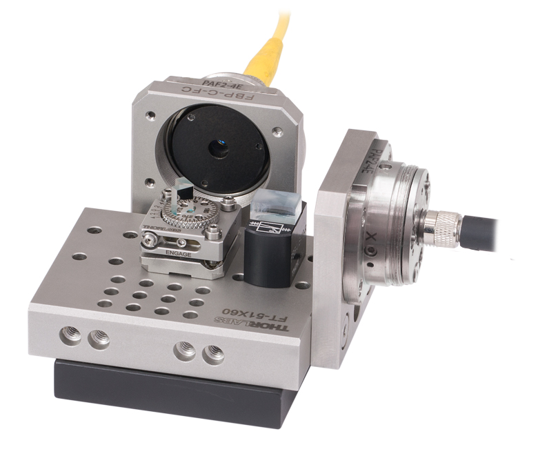
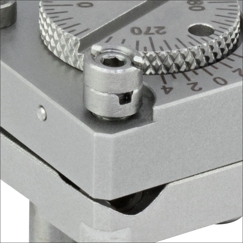
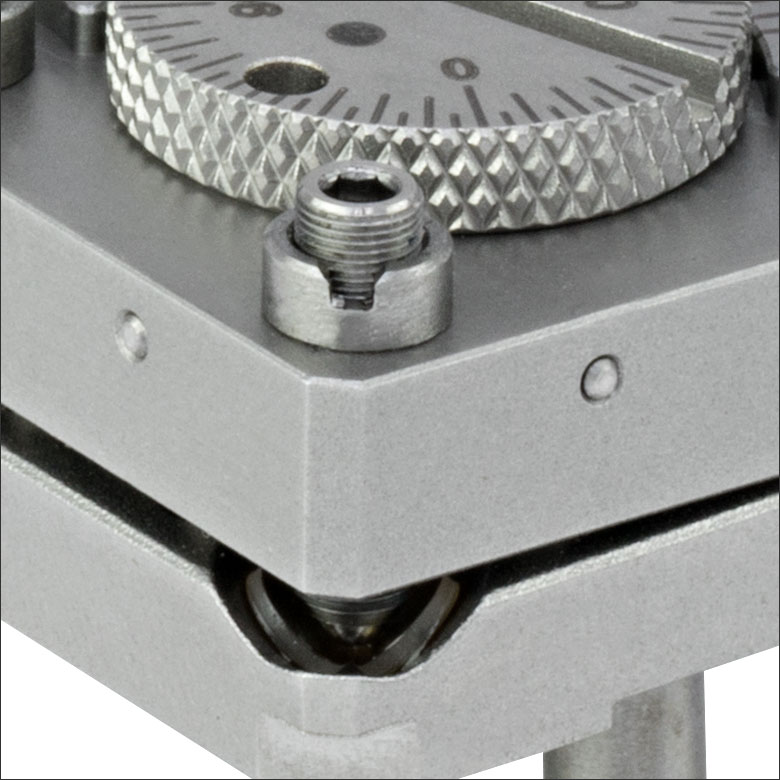
The kinematic base provides tip, tilt, and rotational adjustment for precision beam alignment and steering control. Three adjuster screws control the tip/tilt of the mount (as shown in the image above), yielding up to ±3° of adjustment. Additionally, these screws can also provide some vertical adjustment when all three are rotated by the same amount. A physical stop prevents the tip/tilt springs from being overextended. The circular rotation plate can be rotated a full 360° and is engraved with a scale marked every 5°. Additionally, a Vernier scale provides 1° resolution for fine rotation. When engaged, the fine rotation adjustment screw (see Application Idea photo above) provides up to ±12° adjustment.
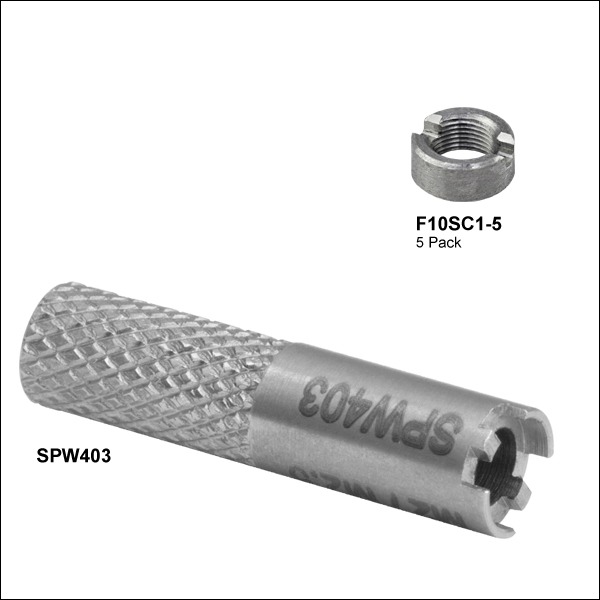
All adjustment screws use a 0.05" hex key, which is included with this mount. Furthermore, they can be locked into position with a spanner wrench to prevent accidental movement. The necessary spanner wrench (SPW403) is included; simply insert the included hex key through the spanner wrench, and while holding the adjustment screw static, use the spanner wrench to tighten the locking nut. Additional locking collars and spanner wrenches are also available for purchase separately. If desired, two locking collars can be used together to create a hard stop. Alternatively, a single collar can be epoxied to an adjuster using our G14250 epoxy to create a permanent hard stop.
| FiberBench Accessories | |||
|---|---|---|---|
| FiberPorts | Optic Mounts | Alignment Tools | Polarizers |
| Beamsplitter Modules | Mirror Modules | Rotating Wave Plates | FiberBenches |
| FBT-P01 Specifications | ||
|---|---|---|
| Mirrors | ||
| Coating | Protected Silver | |
| Reflectance | Ravg > 97% from 450 nm - 2 µm; Ravg > 95% from 2 - 20 µm |
|
| Clear Aperture @ 45° | Ø1.5 mm | |
| On-Axis Beam Gap | 1 mma | |
| Surface Flatness | λ/10 @ 633 nm over Clear Aperture | |
| Damage Thresholds |
Pulsed | 0.225 J/cm2 (800 nm, 99 fs, 1 kHz, Ø0.167 mm) 1 J/cm2 (1064 nm, 10 ns, 10 Hz, Ø1.010 mm) |
| CWb | 1750 W/cm (1.064 µm, Ø0.044 mm) 1500 W/cm (10.6 µm, Ø0.339 mm) |
|
| Kinematic Base | ||
| Tip/Tilt | ±3° Tip/Tilt Adjustment via Three M2.5 x 0.2 Precision Adjusters | |
| Rotation | 360° Continuous Rotation with ±12° Fine Adjustment | |
| Angular Resolution | Rotation Plate Engraved Every 5°; 1° Vernier Scale | |
| Mounting | FiberBench Compatible via Two Ø0.125" (Ø3.2 mm) Dowel Pins | |
Click to Enlarge
Figure G3.2 Polarization Beamsplitter
| Table G3.1 Specifications | ||
|---|---|---|
| Item #a | Qty | Description |
| FT-51X60 | 1 | Multi-Axis FiberBench |
| HCA3 | 2b | FiberBench Wall Plate |
| - | 2b | FiberPort Collimator/Couplerc |
| - | 1 | Calcite Beam Displacer Module |
| FBT-P01 | 1 | Adjustable Offset Mirror Module |
| - | 2b | SM or PM Fiber Patch Cable |
Polarization Splitter
A polarization splitter can be assembled using the components listed in Table G3.1. Since a variety of AR coatings, connectors, and configurations are available, we recommend selecting individual components suited to your application.
The offset (pickoff) mirror is positioned such that it will intersect the displaced beam from the preceding calcite beam displacer (walk-off polarizer) and reflect it by 90°. This combination simplifies the alignment of complex systems by decoupling the reflected beam from the transmitted beam, thus allowing for the independent adjustment of the reflected beam path. Alignment is critical when aligning systems with a walk-off/pickoff combination as clipping can occur if the beam is too large or not centered.
Reading a Vernier Scale on a Linear Main Scale
Vernier scales are typically used to add precision to standard, evenly divided scales (such as the scales on Thorlabs' rotation, goniometric, or translation mounts). A vernier scale has found common use in many precision measurement instruments, the most common being calipers and micrometers. The vernier scale uses two scales side-by-side: the main scale and the vernier scale. The direct vernier scale has a slightly smaller spacing between its tick marks owing to the vernier scale having N ticks for every N - 1 ticks on the main scale. Hence, the lines on the main scale will not line up with all the lines on the vernier scale. Only one line from the vernier scale will match well with one line of the main scale, and that is the trick to reading a vernier scale.
Figures 130A through 130C show a linear vernier scale system for three different situations. In each case, the scale on the left is the main scale, while the small scale on the right is the vernier scale. When reading a vernier scale, the main scale is used for the gross number, and the vernier scale gives the precision value. In this manner, a standard ruler or micrometer can become a precision instrument.
The 0 on the vernier scale is the "pointer" (marked by a red arrow in Figures 130A through 130E) and will indicate the main scale reading. In Figure 130A we see the pointer is lined up directly with the 75.6 line. Notice that the only other vernier scale tick mark that lines up well with the main scale is 10. Since the pointer lines up with the main scale’s 75.6, the reading from Figure 130A is 75.60 (in whatever units the instrument measures).
That is essentially all there is to reading a vernier scale. It's a very straightforward way of increasing the precision of a measurement instrument. To expound, let’s look at Figure 130B. Here we see that the pointer is no longer aligned with a line on the main scale, but instead it is slightly above 75.6 and below 75.7; thus, the gross measurement is 75.6. The first vernier line that coincides with a main scale line is the 5, shown with a blue arrow. The vernier scale gives the final digit of precision; since the 5 is aligned to the main scale, the precision measurement for Figure 130B is 75.65.
Since this vernier scale is 10% smaller than the main scale, moving the vernier scale by 1/10 of the main scale will align the next vernier marking. This asks the obvious question: what if the measurement is within the 1/10 precision of the vernier scale? Figure 130C shows just this. Again, the pointer line is in between 75.6 and 75.7, yielding the gross measurement of 75.6. If we look closely, we see that the vernier scale 7 (marked with a blue arrow) is very closely aligned to the main scale, giving a precision measurement of 75.67. However, the vernier scale 7 is very slightly above the main scale mark, and we can see that the vernier scale 8 (directly above 7) is slightly below its corresponding main scale mark. Hence, the scale on Figure 130C could be read as 75.673 ± 0.002. A reading error of about 0.002 would be appropriate for
this instrument.
Click to Enlarge
Figure 130A An example of how to read a vernier scale. The red arrow indicates what is known as the pointer. Since the tick mark labeled 10 on the vernier scale aligns with one of the tick marks on the main scale, this vernier scale is reading 75.60 (in whatever units the instrument measures).
Click to Enlarge
Figure 130B The red arrow indicates the pointer and the blue arrow indicates the vernier line that matches the main scale. This scale reads 75.65.
Click to Enlarge
Figure 130C The red arrow indicates the pointer, and the blue arrow indicates the vernier line that matches the main scale. This scale reads 75.67 but can be accurately read as
75.673 ± 0.002.
Reading a Vernier Scale on a Rotating Main Scale
The vernier scale may also be used on rotating scales where the main scale and vernier scale do not share units. Figures 130D and 130F show a vernier scale system for two different situations where the main scale is given in degrees and the vernier scale has ticks every 5 arcmin (60 arcmin = 1°). In each case, the scale on the top is the main scale, while the small scale on the bottom is the vernier scale.
In Figure 130D we see the pointer is lined up directly with the 341° line. Notice that the only other vernier scale tick marks that line up well with the main scale are ±60 arcmin. Since the pointer lines up with the main scale at 341°, the reading from Figure 130D is 341.00°.
There are two ways to determine the reading if the zero on the vernier scale line is between two lines of the main scale. For the first method, take the line on the left side of the pointer on the vernier scale and subtract that value (in arcmin) from the value on the main scale that is to the right on the main scale. As an example, in Figure 130E the vernier pointer is between 342° and 343°; using the left blue arrow of the vernier scale results in
As we've seen here, vernier scales add precision to a standard scale measurement. While it takes a bit of getting used to, with a little practice, reading these scales is fairly straightforward. Vernier scales, whether they are direct or retrograde*, are read in the same fashion.
*A retrograde vernier scale has a larger spacing between its tick marks with N ticks for every N + 1 ticks on the main scale.
Click to Enlarge
Figure 130D An example of a vernier scale where the main scale and the vernier scale are in different units (degrees and arcmins, respectively). The red arrow indicates the pointer. This scale reads 341.00°.
Click to Enlarge
Figure 130E The red arrow indicates the pointer and the blue arrows give the precision value from the vernier scale.
This scale reads 342.75°.
| Table G5.1 Damage Threshold Specifications | |
|---|---|
| Coating Designation (Item # Suffix) |
Damage Threshold |
| -P01 (Pulsed) | 0.225 J/cm2 (800 nm, 99 fs, 1 kHz, Ø0.167 mm) 1 J/cm2 (1064 nm, 10 ns, 10 Hz, Ø1.010 mm) |
| -P01 (CW)a | 1750 W/cm (1.064 µm, Ø0.044 mm) 1500 W/cm (10.6 µm, Ø0.339 mm) |
Damage Threshold Data for Thorlabs' Protected Silver Coated Offset Mirrors
The specifications in Table G5.1 are measured data for Thorlabs' protected silver mirrors. Damage threshold specifications are constant for all protected silver coated mirrors, regardless of the size or focal length of the mirror.
Laser Induced Damage Threshold Tutorial
The following is a general overview of how laser induced damage thresholds are measured and how the values may be utilized in determining the appropriateness of an optic for a given application. When choosing optics, it is important to understand the Laser Induced Damage Threshold (LIDT) of the optics being used. The LIDT for an optic greatly depends on the type of laser you are using. Continuous wave (CW) lasers typically cause damage from thermal effects (absorption either in the coating or in the substrate). Pulsed lasers, on the other hand, often strip electrons from the lattice structure of an optic before causing thermal damage. Note that the guideline presented here assumes room temperature operation and optics in new condition (i.e., within scratch-dig spec, surface free of contamination, etc.). Because dust or other particles on the surface of an optic can cause damage at lower thresholds, we recommend keeping surfaces clean and free of debris. For more information on cleaning optics, please see our Optics Cleaning tutorial.
Testing Method
Thorlabs' LIDT testing is done in compliance with ISO/DIS 11254 and ISO 21254 specifications.
First, a low-power/energy beam is directed to the optic under test. The optic is exposed in 10 locations to this laser beam for 30 seconds (CW) or for a number of pulses (pulse repetition frequency specified). After exposure, the optic is examined by a microscope (~100X magnification) for any visible damage. The number of locations that are damaged at a particular power/energy level is recorded. Next, the power/energy is either increased or decreased and the optic is exposed at 10 new locations. This process is repeated until damage is observed. The damage threshold is then assigned to be the highest power/energy that the optic can withstand without causing damage. A histogram such as that shown in Figure 37B represents the testing of one BB1-E02 mirror.
Figure 37A This photograph shows a protected aluminum-coated mirror after LIDT testing. In this particular test, it handled 0.43 J/cm2 (1064 nm, 10 ns pulse, 10 Hz, Ø1.000 mm) before damage.
Figure 37B Example Exposure Histogram used to Determine the LIDT of
| Table 37C Example Test Data | |||
|---|---|---|---|
| Fluence | # of Tested Locations | Locations with Damage | Locations Without Damage |
| 1.50 J/cm2 | 10 | 0 | 10 |
| 1.75 J/cm2 | 10 | 0 | 10 |
| 2.00 J/cm2 | 10 | 0 | 10 |
| 2.25 J/cm2 | 10 | 1 | 9 |
| 3.00 J/cm2 | 10 | 1 | 9 |
| 5.00 J/cm2 | 10 | 9 | 1 |
According to the test, the damage threshold of the mirror was 2.00 J/cm2 (532 nm, 10 ns pulse, 10 Hz, Ø0.803 mm). Please keep in mind that these tests are performed on clean optics, as dirt and contamination can significantly lower the damage threshold of a component. While the test results are only representative of one coating run, Thorlabs specifies damage threshold values that account for coating variances.
Continuous Wave and Long-Pulse Lasers
When an optic is damaged by a continuous wave (CW) laser, it is usually due to the melting of the surface as a result of absorbing the laser's energy or damage to the optical coating (antireflection) [1]. Pulsed lasers with pulse lengths longer than 1 µs can be treated as CW lasers for LIDT discussions.
When pulse lengths are between 1 ns and 1 µs, laser-induced damage can occur either because of absorption or a dielectric breakdown (therefore, a user must check both CW and pulsed LIDT). Absorption is either due to an intrinsic property of the optic or due to surface irregularities; thus LIDT values are only valid for optics meeting or exceeding the surface quality specifications given by a manufacturer. While many optics can handle high power CW lasers, cemented (e.g., achromatic doublets) or highly absorptive (e.g., ND filters) optics tend to have lower CW damage thresholds. These lower thresholds are due to absorption or scattering in the cement or metal coating.
Figure 37D LIDT in linear power density vs. pulse length and spot size. For long pulses to CW, linear power density becomes a constant with spot size. This graph was obtained from [1].
Figure 37E Intensity Distribution of Uniform and Gaussian Beam Profiles
Pulsed lasers with high pulse repetition frequencies (PRF) may behave similarly to CW beams. Unfortunately, this is highly dependent on factors such as absorption and thermal diffusivity, so there is no reliable method for determining when a high PRF laser will damage an optic due to thermal effects. For beams with a high PRF both the average and peak powers must be compared to the equivalent CW power. Additionally, for highly transparent materials, there is little to no drop in the LIDT with increasing PRF.
In order to use the specified CW damage threshold of an optic, it is necessary to know the following:
- Wavelength of your laser
- Beam diameter of your beam (1/e2)
- Approximate intensity profile of your beam (e.g., Gaussian)
- Linear power density of your beam (total power divided by 1/e2 beam diameter)
Thorlabs expresses LIDT for CW lasers as a linear power density measured in W/cm. In this regime, the LIDT given as a linear power density can be applied to any beam diameter; one does not need to compute an adjusted LIDT to adjust for changes in spot size, as demonstrated in Figure 37D. Average linear power density can be calculated using this equation.

This calculation assumes a uniform beam intensity profile. You must now consider hotspots in the beam or other non-uniform intensity profiles and roughly calculate a maximum power density. For reference, a Gaussian beam typically has a maximum power density that is twice that of the uniform beam (see Figure 37E).
Now compare the maximum power density to that which is specified as the LIDT for the optic. If the optic was tested at a wavelength other than your operating wavelength, the damage threshold must be scaled appropriately. A good rule of thumb is that the damage threshold has a linear relationship with wavelength such that as you move to shorter wavelengths, the damage threshold decreases (i.e., a LIDT of 10 W/cm at 1310 nm scales to 5 W/cm at 655 nm):

While this rule of thumb provides a general trend, it is not a quantitative analysis of LIDT vs wavelength. In CW applications, for instance, damage scales more strongly with absorption in the coating and substrate, which does not necessarily scale well with wavelength. While the above procedure provides a good rule of thumb for LIDT values, please contact Tech Support if your wavelength is different from the specified LIDT wavelength. If your power density is less than the adjusted LIDT of the optic, then the optic should work for your application.
Please note that we have a buffer built in between the specified damage thresholds online and the tests which we have done, which accommodates variation between batches. Upon request, we can provide individual test information and a testing certificate. The damage analysis will be carried out on a similar optic (customer's optic will not be damaged). Testing may result in additional costs or lead times. Contact Tech Support for more information.
Pulsed Lasers
As previously stated, pulsed lasers typically induce a different type of damage to the optic than CW lasers. Pulsed lasers often do not heat the optic enough to damage it; instead, pulsed lasers produce strong electric fields capable of inducing dielectric breakdown in the material. Unfortunately, it can be very difficult to compare the LIDT specification of an optic to your laser. There are multiple regimes in which a pulsed laser can damage an optic and this is based on the laser's pulse length. The highlighted columns in Table 37F outline the relevant pulse lengths for our specified LIDT values.
Pulses shorter than 10-9 s cannot be compared to our specified LIDT values with much reliability. In this ultra-short-pulse regime various mechanics, such as multiphoton-avalanche ionization, take over as the predominate damage mechanism [2]. In contrast, pulses between 10-7 s and 10-4 s may cause damage to an optic either because of dielectric breakdown or thermal effects. This means that both CW and pulsed damage thresholds must be compared to the laser beam to determine whether the optic is suitable for your application.
| Table 37F Laser Induced Damage Regimes | ||||
|---|---|---|---|---|
| Pulse Duration | t < 10-9 s | 10-9 < t < 10-7 s | 10-7 < t < 10-4 s | t > 10-4 s |
| Damage Mechanism | Avalanche Ionization | Dielectric Breakdown | Dielectric Breakdown or Thermal | Thermal |
| Relevant Damage Specification | No Comparison (See Above) | Pulsed | Pulsed and CW | CW |
When comparing an LIDT specified for a pulsed laser to your laser, it is essential to know the following:
Figure 37G LIDT in energy density vs. pulse length and spot size. For short pulses, energy density becomes a constant with spot size. This graph was obtained from [1].
- Wavelength of your laser
- Energy density of your beam (total energy divided by 1/e2 area)
- Pulse length of your laser
- Pulse repetition frequency (prf) of your laser
- Beam diameter of your laser (1/e2 )
- Approximate intensity profile of your beam (e.g., Gaussian)
The energy density of your beam should be calculated in terms of J/cm2. Figure 37G shows why expressing the LIDT as an energy density provides the best metric for short pulse sources. In this regime, the LIDT given as an energy density can be applied to any beam diameter; one does not need to compute an adjusted LIDT to adjust for changes in spot size. This calculation assumes a uniform beam intensity profile. You must now adjust this energy density to account for hotspots or other nonuniform intensity profiles and roughly calculate a maximum energy density. For reference a Gaussian beam typically has a maximum energy density that is twice that of the 1/e2 beam.
Now compare the maximum energy density to that which is specified as the LIDT for the optic. If the optic was tested at a wavelength other than your operating wavelength, the damage threshold must be scaled appropriately [3]. A good rule of thumb is that the damage threshold has an inverse square root relationship with wavelength such that as you move to shorter wavelengths, the damage threshold decreases (i.e., a LIDT of 1 J/cm2 at 1064 nm scales to 0.7 J/cm2 at 532 nm):

You now have a wavelength-adjusted energy density, which you will use in the following step.
Beam diameter is also important to know when comparing damage thresholds. While the LIDT, when expressed in units of J/cm², scales independently of spot size; large beam sizes are more likely to illuminate a larger number of defects which can lead to greater variances in the LIDT [4]. For data presented here, a <1 mm beam size was used to measure the LIDT. For beams sizes greater than 5 mm, the LIDT (J/cm2) will not scale independently of beam diameter due to the larger size beam exposing more defects.
The pulse length must now be compensated for. The longer the pulse duration, the more energy the optic can handle. For pulse widths between 1 - 100 ns, an approximation is as follows:

Use this formula to calculate the Adjusted LIDT for an optic based on your pulse length. If your maximum energy density is less than this adjusted LIDT maximum energy density, then the optic should be suitable for your application. Keep in mind that this calculation is only used for pulses between 10-9 s and 10-7 s. For pulses between 10-7 s and 10-4 s, the CW LIDT must also be checked before deeming the optic appropriate for your application.
Please note that we have a buffer built in between the specified damage thresholds online and the tests which we have done, which accommodates variation between batches. Upon request, we can provide individual test information and a testing certificate. Contact Tech Support for more information.
[1] R. M. Wood, Optics and Laser Tech. 29, 517 (1998).
[2] Roger M. Wood, Laser-Induced Damage of Optical Materials (Institute of Physics Publishing, Philadelphia, PA, 2003).
[3] C. W. Carr et al., Phys. Rev. Lett. 91, 127402 (2003).
[4] N. Bloembergen, Appl. Opt. 12, 661 (1973).

In order to illustrate the process of determining whether a given laser system will damage an optic, a number of example calculations of laser induced damage threshold are given below. For assistance with performing similar calculations, we provide a spreadsheet calculator that can be downloaded by clicking the LIDT Calculator button. To use the calculator, enter the specified LIDT value of the optic under consideration and the relevant parameters of your laser system in the green boxes. The spreadsheet will then calculate a linear power density for CW and pulsed systems, as well as an energy density value for pulsed systems. These values are used to calculate adjusted, scaled LIDT values for the optics based on accepted scaling laws. This calculator assumes a Gaussian beam profile, so a correction factor must be introduced for other beam shapes (uniform, etc.). The LIDT scaling laws are determined from empirical relationships; their accuracy is not guaranteed. Remember that absorption by optics or coatings can significantly reduce LIDT in some spectral regions. These LIDT values are not valid for ultrashort pulses less than one nanosecond in duration.
Figure 71A A Gaussian beam profile has about twice the maximum intensity of a uniform beam profile.
CW Laser Example
Suppose that a CW laser system at 1319 nm produces a 0.5 W Gaussian beam that has a 1/e2 diameter of 10 mm. A naive calculation of the average linear power density of this beam would yield a value of 0.5 W/cm, given by the total power divided by the beam diameter:
However, the maximum power density of a Gaussian beam is about twice the maximum power density of a uniform beam, as shown in Figure 71A. Therefore, a more accurate determination of the maximum linear power density of the system is 1 W/cm.
An AC127-030-C achromatic doublet lens has a specified CW LIDT of 350 W/cm, as tested at 1550 nm. CW damage threshold values typically scale directly with the wavelength of the laser source, so this yields an adjusted LIDT value:
The adjusted LIDT value of 350 W/cm x (1319 nm / 1550 nm) = 298 W/cm is significantly higher than the calculated maximum linear power density of the laser system, so it would be safe to use this doublet lens for this application.
Pulsed Nanosecond Laser Example: Scaling for Different Pulse Durations
Suppose that a pulsed Nd:YAG laser system is frequency tripled to produce a 10 Hz output, consisting of 2 ns output pulses at 355 nm, each with 1 J of energy, in a Gaussian beam with a 1.9 cm beam diameter (1/e2). The average energy density of each pulse is found by dividing the pulse energy by the beam area:
As described above, the maximum energy density of a Gaussian beam is about twice the average energy density. So, the maximum energy density of this beam is ~0.7 J/cm2.
The energy density of the beam can be compared to the LIDT values of 1 J/cm2 and 3.5 J/cm2 for a BB1-E01 broadband dielectric mirror and an NB1-K08 Nd:YAG laser line mirror, respectively. Both of these LIDT values, while measured at 355 nm, were determined with a 10 ns pulsed laser at 10 Hz. Therefore, an adjustment must be applied for the shorter pulse duration of the system under consideration. As described on the previous tab, LIDT values in the nanosecond pulse regime scale with the square root of the laser pulse duration:
This adjustment factor results in LIDT values of 0.45 J/cm2 for the BB1-E01 broadband mirror and 1.6 J/cm2 for the Nd:YAG laser line mirror, which are to be compared with the 0.7 J/cm2 maximum energy density of the beam. While the broadband mirror would likely be damaged by the laser, the more specialized laser line mirror is appropriate for use with this system.
Pulsed Nanosecond Laser Example: Scaling for Different Wavelengths
Suppose that a pulsed laser system emits 10 ns pulses at 2.5 Hz, each with 100 mJ of energy at 1064 nm in a 16 mm diameter beam (1/e2) that must be attenuated with a neutral density filter. For a Gaussian output, these specifications result in a maximum energy density of 0.1 J/cm2. The damage threshold of an NDUV10A Ø25 mm, OD 1.0, reflective neutral density filter is 0.05 J/cm2 for 10 ns pulses at 355 nm, while the damage threshold of the similar NE10A absorptive filter is 10 J/cm2 for 10 ns pulses at 532 nm. As described on the previous tab, the LIDT value of an optic scales with the square root of the wavelength in the nanosecond pulse regime:
This scaling gives adjusted LIDT values of 0.08 J/cm2 for the reflective filter and 14 J/cm2 for the absorptive filter. In this case, the absorptive filter is the best choice in order to avoid optical damage.
Pulsed Microsecond Laser Example
Consider a laser system that produces 1 µs pulses, each containing 150 µJ of energy at a repetition rate of 50 kHz, resulting in a relatively high duty cycle of 5%. This system falls somewhere between the regimes of CW and pulsed laser induced damage, and could potentially damage an optic by mechanisms associated with either regime. As a result, both CW and pulsed LIDT values must be compared to the properties of the laser system to ensure safe operation.
If this relatively long-pulse laser emits a Gaussian 12.7 mm diameter beam (1/e2) at 980 nm, then the resulting output has a linear power density of 5.9 W/cm and an energy density of 1.2 x 10⁻⁴ J/cm2 per pulse. This can be compared to the LIDT values for a WPQ10E-980 polymer zero-order quarter-wave plate, which are 5 W/cm for CW radiation at 810 nm and 5 J/cm2 for a 10 ns pulse at 810 nm. As before, the CW LIDT of the optic scales linearly with the laser wavelength, resulting in an adjusted CW value of 6 W/cm at 980 nm. On the other hand, the pulsed LIDT scales with the square root of the laser wavelength and the square root of the pulse duration, resulting in an adjusted value of 55 J/cm2 for a 1 µs pulse at 980 nm. The pulsed LIDT of the optic is significantly greater than the energy density of the laser pulse, so individual pulses will not damage the wave plate. However, the large average linear power density of the laser system may cause thermal damage to the optic, much like a high-power CW beam.
| Posted Comments: | |
| No Comments Posted |

 Zoom
Zoom
Click to Enlarge
Figure 579B Two Collars Can be Locked Together to Create a Hard Stop
Click to Enlarge
Figure 579A A Single Locking Collar Can Lock an Adjuster in Position
- Extremely Compact Lock Nut: 0.07" (1.7 mm) Thick
- Use One Collar to Lock an Adjuster to a Bushing
- Use Two Collars to Create a Hard Stop on an Adjuster
- Sold in Packages of Five
- Install and Remove with the SPW403 Spanner Wrench, Sold Below
These locking collars are compatible with the adjusters used in all of the modules sold above, as well as all of our other M2.5 x 0.20 adjusters. They are only 0.07" (1.7 mm) thick and are constructed of 303 stainless steel.
As shown in Figures 579A and 579B, they can be used to lock an adjuster in a desired position, or to create a hard stop at any position to prevent overdriving an adjuster. In addition to using two collars to create a hard stop, as shown in Figure 579B, a single collar can be epoxied to an adjuster using our G14250 epoxy to create a permanent hard stop. We recommend the SPW403 Spanner Wrench to install or remove these locking collars. The end of the SPW403 is machined to accept a 5/64" hex wrench, which can be used to provide additional torque. The hollow cylindrical construction of the SPW403 allows a tool to pass through the entire length of the spanner wrench and access the adjuster.