 Products Home / Optical Fiber & Fiber Patch Cables / Polarization-Maintaining Optical Fiber / Polarization-Maintaining Single Mode Optical Fiber
Polarization-Maintaining Single Mode Optical Fiber
- 350 nm to 2200 nm Operating Wavelengths
- Fibers with Ø80 µm or Ø125 µm Cladding
- Bow-Tie or PANDA Stress Rod Configurations
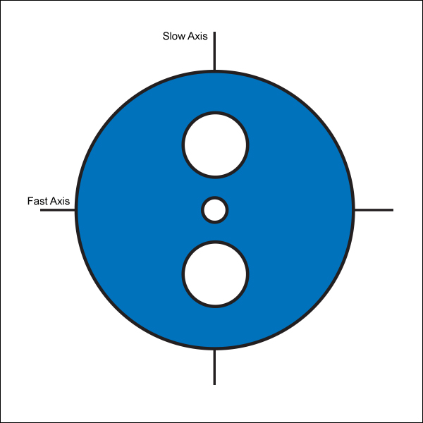
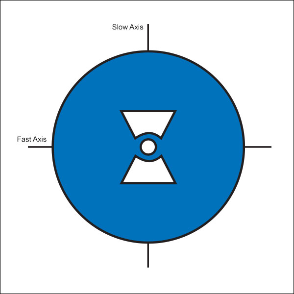
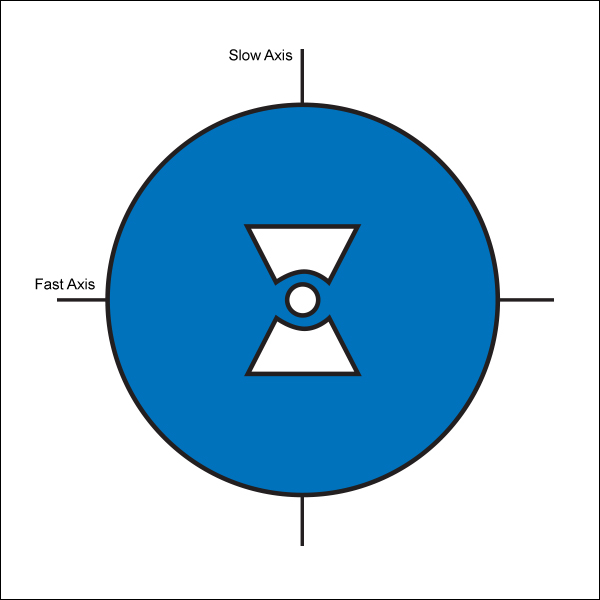
Bow-Tie PM Fiber
PANDA PM Fiber
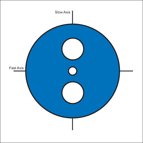
Fast Axis
Slow Axis
PM-405
400 - 488 nm,
PM Fiber with Pure Silica Core


Please Wait

| Stock Patch Cables Available with these Fibers | ||
|---|---|---|
| Type | Fibers Available | |
| Standard | FC/PC | PM-S405-XP, PM460-HP, PM630-HP, PM780-HP, PM980-XP, PM1300-XP, PM1550-XP, PM2000 |
| FC/APC | ||
| Hybrid | ||
| AR-Coated | PM630-HP, PM780-HP, PM980-XP, PM1550-XP |
|
| Reflective-Coated | PM980-XP | |
| Available PM Fiber Types | |
|---|---|
| PANDA | Pure Silica Core |
| Standard | |
| Photosensitive | |
| Dispersion Compensating | |
| Bow-Tie | Standard |
| Bend- and Temperature-Insensitive |
|
Features
- Maintain Polarization State of Input
- PANDA or Bow-Tie Fiber
- Specialized Photosensitive, Dispersion-Compensating, and Bend/Temperature-Insensitive Fibers Available
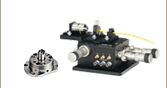
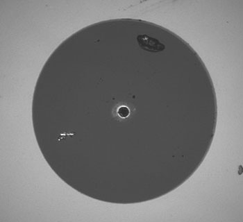
Thorlabs offers both PANDA and Bow-Tie Single Mode Polarization-Maintaining (PM) fiber. These two fibers are named based on the stress rods used. Stress rods run parallel to the fiber's core and apply stress that creates birefringence in the fiber's core, allowing polarization-maintaining operation. PANDA stress rods are cylindrical, while bow-tie uses trapezoidal prism stress rods, as shown in the images above. For the average user, these two fiber types are interchangeable. PANDA fibers have historically been used in telecom applications, as it is easier to maintain uniformity in their cylindrical stress rods over very long lengths when manufacturing.
We also offer specialized PM fibers. Our photosensitive fiber can be exposed to UV light to create a Fiber Bragg Grating, our dispersion-compensating fiber corrects for chromatic dispersion, and our bend- and temperature-insensitive PM fiber is ideal for use in fiber optic gyroscopes (FOG).
PANDA Fibers, Pure Silica Core, 350 - 680 nm
| Item # | Wavelength Range |
MFDa | NAb | Cut-Off Wavelength |
Attenuation | Beat Length | Birefringence | Core Index |
Cladding Index |
|---|---|---|---|---|---|---|---|---|---|
| PM-S350-HP | 350 - 460 nm | 2.3 µm @ 350 nm | 0.12 | ≤340 nm | - | 1.5 mm @ 350 nm | 2.5 x 10⁻⁴ | Callc | Callc |
| PM-405 | 400 - 488 nm | 3.5 ± 0.5 µm @ 410 µm | 0.09 | 365 ± 35 nm | ≤50.0 dB/km @ 410 nm | ≤1.7 mm @ 410 nm | 5 x 10⁻⁴ | ||
| PM-S405-XP | 400 - 680 nm | 3.3 ± 0.5 µm @ 405 nm 4.6 ± 0.5 µm @ 630 nm |
0.12 | 380 ± 20 nm | ≤30.0 dB/km @ 488 nm ≤30.0 dB/km @ 630 nm |
2.0 mm @ 405 nm | 2.5 x 10⁻⁴ |
| Item # | Core Diameter |
Cladding Diameter |
Coating Diameter |
Core-Clad Offset |
Coating Concentricity |
Coating Material |
Core Type |
Operating Temperature Range |
Proof Test Level |
Strip Tool |
|---|---|---|---|---|---|---|---|---|---|---|
| PM-S350-HP | 2.5 µm | 125 ± 2 µm | 245 ± 15 µm | ≤0.5 µm | <5 µm | UV Cured Dual Acrylate |
Pure Silica | -40 to 85 °C | ≥200 kpsi (1.4 GN/m2) | T06S13 |
| PM-405 | 2.9 µm | - | -40 to 85 °C | ≥100 kpsi (0.7 GN/m2) | ||||||
| PM-S405-XP | 3.0 µm | <5.0 µm | -60 to 85 °C | ≥200 kpsi (1.4 GN/m2) |
PANDA Fibers, 460 - 2200 nm
| Item # | Wavelength Range |
MFDa | NAb | Core Index |
Cladding Index |
Cut-Off Wavelength |
Attenuation | Beat Length |
Birefringence | Normalized Cross Talk |
|---|---|---|---|---|---|---|---|---|---|---|
| PM460-HP | 460 - 700 nm | 3.3 ± 0.5 µm @ 515 nm | 0.12 | Callc | Callc | 410 ± 40 nm | ≤100 dB/km @ 488 nm |
1.3 mm @ 460 nm |
3.5 x 10⁻⁴ | - |
| PM630-HP | 620 - 850 nm | 4.5 ± 0.5 µm @ 630 nm | Callc | Callc | 570 ± 50 nm | ≤15 dB/km @ 630 nm |
1.8 mm @ 630 nm |
- | ||
| PM780-HP | 770 - 1100 nm | 5.3 ± 1.0 µm @ 850 nm | Callc | Callc | 710 ± 60 nm | ≤4 dB/km @ 850 nm |
2.4 mm @ 850 nm |
≤-40 dB @ 4 m @ 850 nm | ||
| PM980-XP | 970 - 1550 nm | 6.6 ± 0.5 µm @ 980 nm | Callc | Callc | 920 ± 50 nm | ≤2.5 dB/km @ 980 nm |
≤2.7 mm @ 980 nm |
- | ≤-40 dB @ 4 m ≤-30 dB @ 100 m (Nominal) |
|
| PM1300-XP | 9.3 ± 0.5 µm @ 1300 nm | Callc | Callc | 1210 ± 60 nm | ≤1.0 dB/km @ 1300 nm |
≤4.0 mm @ 1300 nm |
- | |||
| PM1550-XP | 10.1 ± 0.4 µm @ 1550 nm | 0.125 | Callc | Callc | 1380 ± 60 nm | <1.0 dB/km @ 1550 nm |
≤5.0 mm @ 1550 nm |
- | ≤-40 dB @ 4 m @ 1550 nm |
|
| PM2000 | 8.0 µm @ 1950 nm | 0.20 | Callc | Callc | 1720 ± 80 nm | <11.5 dB/km @ 1950 nm <22.5 dB/km @ 2000 nm |
5.2 mm @ 1950 nm |
- | - |
| Item # | Core Diameter |
Cladding Diameter |
Coating Diameter |
Core-Clad Offset |
Coating Concentricity |
Coating Material |
Operating Temperature Range |
Proof Test Level |
Strip Tool |
|---|---|---|---|---|---|---|---|---|---|
| PM460-HP | 3.0 µm | 125 ± 2 µm | 245 ± 15 µm | ≤0.5 µm | <5 µm | UV-Cured Dual Acrylate |
-40 to 85 °C | ≥200 kpsi (1.4 GN/m2) | T06S13 |
| PM630-HP | 3.5 µm | ||||||||
| PM780-HP | 4.5 µm | ||||||||
| PM980-XP | 5.5 µm | 200 kpsi (1.4 GN/m2) | |||||||
| PM1300-XP | 8.0 µm | ≥200 kpsi (1.4 GN/m2) | |||||||
| PM1550-XP | 8.5 µm | ≥200 kpsi (1.4 GN/m2) | |||||||
| PM2000 | 7.0 µm | ≥100 kpsi (0.7 GN/m2) |
Photosensitive PANDA Fiber, 980 nm
| Item # | Operating Wavelength |
MFD | NA | Core Index |
Cladding Index |
Cut-Off Wavelength |
Attenuation | Beat Length |
Normalized Cross Talk |
|---|---|---|---|---|---|---|---|---|---|
| PS-PM980 | 970 - 1550 nm | 6.6 ± 1.0 μm @ 980 nm | 0.12 | Calla | Calla | 900 ± 70 nm | ≤3.0 dB/km @ 980 nm | ≤3.5 mm @ 980 nm | ≤-40 dB @ 4 m ≤-25 dB @ 100 m (Nominal) |
| Item # | Core Diameter |
Cladding Diameter |
Coating Diameter |
Core-Clad Concentricity |
Coating-Clad Offset |
Coating Material |
Operating Temperature Range |
Proof Test Level |
Strip Tool |
|---|---|---|---|---|---|---|---|---|---|
| PS-PM980 | 6.0 µm | 125 ± 1.0 µm | 245 ± 15 µm | <0.5 µm | ≤5 µm | UV Cured Dual Acrylate |
-40 to 85 °C | ≥100 kpsi (0.7 GN/m2) | T06S13 |
PANDA, Dispersion-Compensating Fiber, 1510 - 1620 nm
| Item # | Operating Wavelength |
MFD | NA | Core Index | Cladding Index | Cut-Off Wavelength, Slow-Axis |
Attenuation | Beat Lengtha | Core Diameter |
|---|---|---|---|---|---|---|---|---|---|
| PMDCF | 1510 - 1620 nm | 5 µm @ 1550 nm | Proprietaryb | Callc | Callc | 1400 nm | 0.40 dB/km (Typical) @ 1550 nm 0.45 dB/km (Max) @ 1550 nm |
5 mm | Proprietaryd |
| Item # | Cladding Diametera |
Coating Diametera | Effective Areab | Differential Group Delayb |
Splicing Loss, Directb,c | Dispersiond | Dispersion Sloped | Relative Dispersion Sloped |
Group Velocity Dispersiond | β3/β2d | Strip Tool |
|---|---|---|---|---|---|---|---|---|---|---|---|
| PMDCF | 125 ± 1.5 µm | 250 ± 10 µm | 20 µm2 | 2 ps/m | 1 dB | -100 ± 10 ps/(nm•km) | -0.34 ps/(nm2•km) | 0.0034 ± 0.0004 nm-1 | 1.275 x 10⁵ fs2/m | -6 fs | T06S13 |
Bow-Tie Fibers, 980 - 1310 nm
| Item # | Design Wavelengtha | MFDb | NA | Core Indexc | Cladding Indexc | Cut-Off Wavelength | Attenuation | Beat Lengthd |
|---|---|---|---|---|---|---|---|---|
| HB980T | 980 nm | 5.3 - 6.4 µm | 0.13 - 0.15 | 980 nm: 1.45647e | 980 nm: 1.45068e | 870 - 970 nm | ≤3 dB/km | ≤2.0 mm |
| HB1250T | 1310 nm | 8.1 - 9.9 µm | 0.11 - 0.13 | 1310 nm: 1.45094f | 1310 nm: 1.44680f | 1100 - 1290 nm | <2 dB/km | <2.0 mm |
| Item # | Cladding Diameter | Coating Diameter | Core-Clad Concentricity | Coating Material | Proof Test Level | Strip Tool |
|---|---|---|---|---|---|---|
| HB980T | 125 ± 1 µm | 245 ± 15 µm | ≤0.6 µm | Dual-Layer Acrylate | 100 kpsi (1%) | T06S13 |
| HB1250T | 400 µm ± 5% | T06S16 |
Bend- and Temperature-Insensitive Bow-Tie Fiber, 800 - 1000 nm
| Item # | Design Wavelengtha | MFDb | NA | Core Indexc | Cladding Indexc | Cut-Off Wavelength | Attenuation | Beat Lengthd |
|---|---|---|---|---|---|---|---|---|
| HB800G | 830 nm | 3.7 - 4.9 µm | 0.14 - 0.18 | 830 nm: 1.45954e | 830 nm: 1.45282e | 660 - 800 nm | ≤5 dB/km | ≤1.5 mm |
| Item # | Cladding Diameter |
Coating Diameter |
Core-Clad Concentricity |
Coating Material | Proof Test Level | Strip Tool |
|---|---|---|---|---|---|---|
| HB800G | 80 ± 1 µm | 165 ±10 µm | ≤1 µm | Dual Acrylate | 100 kpsi (1%) | T04S10 |
Click to Enlarge
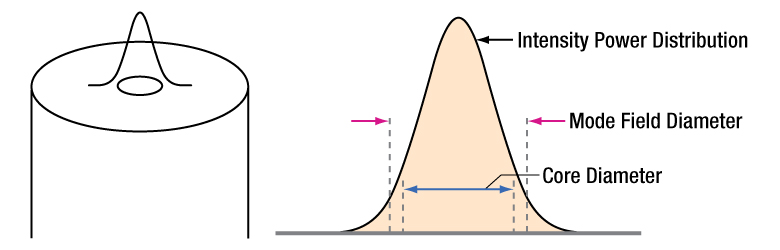
Figure 75A The left image shows the intensity profile of the beam propagated through the fiber overlaid on the fiber itself. The right image shows the standard intensity profile of the beam propagated through the fiber with the MFD and core diameter called out.
Definition of the Mode Field Diameter
The mode field diameter (MFD) is one measure of the beam width of light propagating in a single mode fiber. It is a function of wavelength, core radius, and the refractive indices of the core and cladding. While much of the light in an optical fiber is trapped within the fiber core, a small fraction propagates in the cladding. The light can be approximated as a Gaussian power distribution as shown in Figure 75A, where the MFD is the diameter at which the optical power is reduced to 1/e2 from its peak level.
Measurement of MFD
The measurement of MFD is accomplished by the Variable Aperture Method in the Far Field (VAMFF). An aperture is placed in the far field of the fiber output, and the intensity is measured. As successively smaller apertures are placed in the beam, the intensity levels are measured for each aperture; the data can then be plotted as power vs. the sine of the aperture half-angle (or the numerical aperture for an SM fiber).
The MFD is then determined using Petermann's second definition, which is a mathematical model that does not assume a specific shape of power distribution. The MFD in the near field can be determined from this far-field measurement using the Hankel Transform.
| Quick Links |
|---|
| Damage at the Air / Glass Interface |
| Intrinsic Damage Threshold |
| Preparation and Handling of Optical Fibers |
Laser-Induced Damage in Silica Optical Fibers
The following tutorial details damage mechanisms relevant to unterminated (bare) fiber, terminated optical fiber, and other fiber components from laser light sources. These mechanisms include damage that occurs at the air / glass interface (when free-space coupling or when using connectors) and in the optical fiber itself. A fiber component, such as a bare fiber, patch cable, or fused coupler, may have multiple potential avenues for damage (e.g., connectors, fiber end faces, and the device itself). The maximum power that a fiber can handle will always be limited by the lowest limit of any of these damage mechanisms.
While the damage threshold can be estimated using scaling relations and general rules, absolute damage thresholds in optical fibers are very application dependent and user specific. Users can use this guide to estimate a safe power level that minimizes the risk of damage. Following all appropriate preparation and handling guidelines, users should be able to operate a fiber component up to the specified maximum power level; if no maximum is specified for a component, users should abide by the "practical safe level" described below for safe operation of the component. Factors that can reduce power handling and cause damage to a fiber component include, but are not limited to, misalignment during fiber coupling, contamination of the fiber end face, or imperfections in the fiber itself. For further discussion about an optical fiber’s power handling abilities for a specific application, please contact Thorlabs’ Tech Support.
Damage at the Air / Glass Interface
There are several potential damage mechanisms that can occur at the air / glass interface. Light is incident on this interface when free-space coupling or when two fibers are mated using optical connectors. High-intensity light can damage the end face leading to reduced power handling and permanent damage to the fiber. For fibers terminated with optical connectors where the connectors are fixed to the fiber ends using epoxy, the heat generated by high-intensity light can burn the epoxy and leave residues on the fiber facet directly in the beam path.
| Table 36C Estimated Optical Power Densities on Air / Glass Interfacea | ||
|---|---|---|
| Type | Theoretical Damage Thresholdb | Practical Safe Levelc |
| CW (Average Power) |
~1 MW/cm2 | ~250 kW/cm2 |
| 10 ns Pulsed (Peak Power) |
~5 GW/cm2 | ~1 GW/cm2 |
Damage Mechanisms on the Bare Fiber End Face
Damage mechanisms on a fiber end face can be modeled similarly to bulk optics, and industry-standard damage thresholds for UV Fused Silica substrates can be applied to silica-based fiber. However, unlike bulk optics, the relevant surface areas and beam diameters involved at the air / glass interface of an optical fiber are very small, particularly for coupling into single mode (SM) fiber. therefore, for a given power density, the power incident on the fiber needs to be lower for a smaller beam diameter.
Table 36C lists two thresholds for optical power densities: a theoretical damage threshold and a "practical safe level". In general, the theoretical damage threshold represents the estimated maximum power density that can be incident on the fiber end face without risking damage with very good fiber end face and coupling conditions. The "practical safe level" power density represents minimal risk of fiber damage. Operating a fiber or component beyond the practical safe level is possible, but users must follow the appropriate handling instructions and verify performance at low powers prior to use.
Calculating the Effective Area for Single Mode Fibers
The effective area for single mode (SM) fiber is defined by the mode field diameter (MFD), which is the cross-sectional area through which light propagates in the fiber; this area includes the fiber core and also a portion of the cladding. To achieve good efficiency when coupling into a single mode fiber, the diameter of the input beam must match the MFD of the fiber.
As an example, SM400 single mode fiber has a mode field diameter (MFD) of ~Ø3 µm operating at 400 nm, while the MFD for SMF-28 Ultra single mode fiber operating at 1550 nm is Ø10.5 µm. The effective area for these fibers can be calculated as follows:
SM400 Fiber: Area = Pi x (MFD/2)2 = Pi x (1.5 µm)2 = 7.07 µm2 = 7.07 x 10⁻⁸ cm2
SMF-28 Ultra Fiber: Area = Pi x (MFD/2)2 = Pi x (5.25 µm)2 = 86.6 µm2 = 8.66 x 10⁻⁷ cm2
To estimate the power level that a fiber facet can handle, the power density is multiplied by the effective area. Please note that this calculation assumes a uniform intensity profile, but most laser beams exhibit a Gaussian-like shape within single mode fiber, resulting in a higher power density at the center of the beam compared to the edges. Therefore, these calculations will slightly overestimate the power corresponding to the damage threshold or the practical safe level. Using the estimated power densities assuming a CW light source, we can determine the corresponding power levels as:
SM400 Fiber: 7.07 x 10⁻⁸ cm2 x 1 MW/cm2 = 7.1 x 10⁻⁸ MW = 71 mW (Theoretical Damage Threshold)
7.07 x 10⁻⁸ cm2 x 250 kW/cm2 = 1.8 x 10⁻⁵ kW = 18 mW (Practical Safe Level)
SMF-28 Ultra Fiber: 8.66 x 10⁻⁷ cm2 x 1 MW/cm2 = 8.7 x 10⁻⁷ MW = 870 mW (Theoretical Damage Threshold)
8.66 x 10⁻⁷ cm2 x 250 kW/cm2 = 2.1 x 10⁻⁴ kW = 210 mW (Practical Safe Level)
Effective Area of Multimode Fibers
The effective area of a multimode (MM) fiber is defined by the core diameter, which is typically far larger than the MFD of an SM fiber. For optimal coupling, Thorlabs recommends focusing a beam to a spot roughly 70 - 80% of the core diameter. The larger effective area of MM fibers lowers the power density on the fiber end face, allowing higher optical powers (typically on the order of kilowatts) to be coupled into multimode fiber without damage.
Damage Mechanisms Related to Ferrule / Connector Termination
 Click to Enlarge
Figure 36D Plot showing approximate input power that can be incident on a single mode silica optical fiber with a termination. Each line shows the estimated power level due to a specific damage mechanism. The maximum power handling is limited by the lowest power level from all relevant damage mechanisms (indicated by a solid line).
Fibers terminated with optical connectors have additional power handling considerations. Fiber is typically terminated using epoxy to bond the fiber to a ceramic or steel ferrule. When light is coupled into the fiber through a connector, light that does not enter the core and propagate down the fiber is scattered into the outer layers of the fiber, into the ferrule, and the epoxy used to hold the fiber in the ferrule. If the light is intense enough, it can burn the epoxy, causing it to vaporize and deposit a residue on the face of the connector. This results in localized absorption sites on the fiber end face that reduce coupling efficiency and increase scattering, causing further damage.
For several reasons, epoxy-related damage is dependent on the wavelength. In general, light scatters more strongly at short wavelengths than at longer wavelengths. Misalignment when coupling is also more likely due to the small MFD of short-wavelength SM fiber that also produces more scattered light.
To minimize the risk of burning the epoxy, fiber connectors can be constructed to have an epoxy-free air gap between the optical fiber and ferrule near the fiber end face. Our high-power multimode fiber patch cables use connectors with this design feature.
Determining Power Handling with Multiple Damage Mechanisms
When fiber cables or components have multiple avenues for damage (e.g., fiber patch cables), the maximum power handling is always limited by the lowest damage threshold that is relevant to the fiber component. In general, this represents the highest input power that can be incident on the patch cable end face and not the coupled output power.
As an illustrative example, Figure 36D shows an estimate of the power handling limitations of a single mode fiber patch cable due to damage to the fiber end face and damage via an optical connector. The total input power handling of a terminated fiber at a given wavelength is limited by the lower of the two limitations at any given wavelength (indicated by the solid lines). A single mode fiber operating at around 488 nm is primarily limited by damage to the fiber end face (blue solid line), but fibers operating at 1550 nm are limited by damage to the optical connector (red solid line).
In the case of a multimode fiber, the effective mode area is defined by the core diameter, which is larger than the effective mode area for SM fiber. This results in a lower power density on the fiber end face and allows higher optical powers (on the order of kilowatts) to be coupled into the fiber without damage (not shown in graph). However, the damage limit of the ferrule / connector termination remains unchanged and as a result, the maximum power handling for a multimode fiber is limited by the ferrule and connector termination.
Please note that these are rough estimates of power levels where damage is very unlikely with proper handling and alignment procedures. It is worth noting that optical fibers are frequently used at power levels above those described here. However, these applications typically require expert users and testing at lower powers first to minimize risk of damage. Even still, optical fiber components should be considered a consumable lab supply if used at high power levels.
Intrinsic Damage Threshold
In addition to damage mechanisms at the air / glass interface, optical fibers also display power handling limitations due to damage mechanisms within the optical fiber itself. These limitations will affect all fiber components as they are intrinsic to the fiber itself. Two categories of damage within the fiber are damage from bend losses and damage from photodarkening.
Bend Losses
Bend losses occur when a fiber is bent to a point where light traveling in the core is incident on the core/cladding interface at an angle higher than the critical angle, making total internal reflection impossible. Under these circumstances, light escapes the fiber, often in a localized area. The light escaping the fiber typically has a high power density, which burns the fiber coating as well as any surrounding furcation tubing.
A special category of optical fiber, called double-clad fiber, can reduce the risk of bend-loss damage by allowing the fiber’s cladding (2nd layer) to also function as a waveguide in addition to the core. By making the critical angle of the cladding/coating interface higher than the critical angle of the core/clad interface, light that escapes the core is loosely confined within the cladding. It will then leak out over a distance of centimeters or meters instead of at one localized spot within the fiber, minimizing the risk of damage. Thorlabs manufactures and sells 0.22 NA double-clad multimode fiber, which boasts very high, megawatt range power handling.
Photodarkening
A second damage mechanism, called photodarkening or solarization, can occur in fibers used with ultraviolet or short-wavelength visible light, particularly those with germanium-doped cores. Fibers used at these wavelengths will experience increased attenuation over time. The mechanism that causes photodarkening is largely unknown, but several fiber designs have been developed to mitigate it. For example, fibers with a very low hydroxyl ion (OH) content have been found to resist photodarkening and using other dopants, such as fluorine, can also reduce photodarkening.
Even with the above strategies in place, all fibers eventually experience photodarkening when used with UV or short-wavelength light, and thus, fibers used at these wavelengths should be considered consumables.
Preparation and Handling of Optical Fibers
General Cleaning and Operation Guidelines
These general cleaning and operation guidelines are recommended for all fiber optic products. Users should still follow specific guidelines for an individual product as outlined in the support documentation or manual. Damage threshold calculations only apply when all appropriate cleaning and handling procedures are followed.
-
All light sources should be turned off prior to installing or integrating optical fibers (terminated or bare). This ensures that focused beams of light are not incident on fragile parts of the connector or fiber, which can possibly cause damage.
-
The power-handling capability of an optical fiber is directly linked to the quality of the fiber/connector end face. Always inspect the fiber end prior to connecting the fiber to an optical system. The fiber end face should be clean and clear of dirt and other contaminants that can cause scattering of coupled light. Bare fiber should be cleaved prior to use and users should inspect the fiber end to ensure a good quality cleave is achieved.
-
If an optical fiber is to be spliced into the optical system, users should first verify that the splice is of good quality at a low optical power prior to high-power use. Poor splice quality may increase light scattering at the splice interface, which can be a source of fiber damage.
-
Users should use low power when aligning the system and optimizing coupling; this minimizes exposure of other parts of the fiber (other than the core) to light. Damage from scattered light can occur if a high power beam is focused on the cladding, coating, or connector.
Tips for Using Fiber at Higher Optical Power
Optical fibers and fiber components should generally be operated within safe power level limits, but under ideal conditions (very good optical alignment and very clean optical end faces), the power handling of a fiber component may be increased. Users must verify the performance and stability of a fiber component within their system prior to increasing input or output power and follow all necessary safety and operation instructions. The tips below are useful suggestions when considering increasing optical power in an optical fiber or component.
-
Splicing a fiber component into a system using a fiber splicer can increase power handling as it minimizes possibility of air/fiber interface damage. Users should follow all appropriate guidelines to prepare and make a high-quality fiber splice. Poor splices can lead to scattering or regions of highly localized heat at the splice interface that can damage the fiber.
-
After connecting the fiber or component, the system should be tested and aligned using a light source at low power. The system power can be ramped up slowly to the desired output power while periodically verifying all components are properly aligned and that coupling efficiency is not changing with respect to optical launch power.
-
Bend losses that result from sharply bending a fiber can cause light to leak from the fiber in the stressed area. When operating at high power, the localized heating that can occur when a large amount of light escapes a small localized area (the stressed region) can damage the fiber. Avoid disturbing or accidently bending fibers during operation to minimize bend losses.
-
Users should always choose the appropriate optical fiber for a given application. For example, large-mode-area fibers are a good alternative to standard single mode fibers in high-power applications as they provide good beam quality with a larger MFD, decreasing the power density on the air/fiber interface.
-
Step-index silica single mode fibers are normally not used for ultraviolet light or high-peak-power pulsed applications due to the high spatial power densities associated with these applications.
| Posted Comments: | |
SeungYu Jeong
(posted 2025-10-01 02:11:21.923) Hello, I am currently working on a fiber-based laser system, and I would like to characterize the pulse dispersion in our setup.
Could you please provide the second-order (GVD) and third-order dispersion (TOD) data for the PM980-XP fiber?
Thank you. EGies
(posted 2025-10-08 12:38:17.0) Thank you for contacting Thorlabs. I have reached out to you directly regarding this. Further specs and data can be requested by emailing us directly at techsupport@thorlabs.com. Dylan Black
(posted 2025-03-14 13:35:15.44) Hello, could you send me the refractive index of the PM980-XP and the dispersion data around 1030 nm?Thank you! jdelia
(posted 2025-03-17 09:01:50.0) Thank you for contacting Thorlabs. I have contacted you directly via email to share these values. For future inquiries like this, you may reach out directly to your local tech support team. user
(posted 2025-03-12 17:08:22.647) Hi thorlabs, I would like to know does PM630-HP's NA (0.12) is calculated under 1/e2 of the gaussian beam? Thank you. cdolbashian
(posted 2025-03-20 12:34:16.0) Thank you for reaching out to us with inquiry! The NA of the fiber is determined from the relationship between the index of the core and cladding of the glass of the fiber, rather than specific beam parameters. I have contacted you directly to share more information regarding the difference between the NA of a single mode fiber compared with the divergence angle of a TEM00 beam exiting a polished SM fiber end face. Cristina Amaya Mendez
(posted 2024-11-15 13:33:50.91) Dear Thorlabs team,
I would like to know the core and index cladding of the PM1550-XP for a wavelength of 1950 nm.
Would it be possible to get a graph of the refractive index of the core as a function of wavelength as well?
Thank you in advance! EGies
(posted 2024-11-18 12:38:53.0) Thank you for contacting Thorlabs. We have reached out to you directly regarding the refractive index info for PM1550-XP. Linslal C L
(posted 2024-10-28 18:31:57.98) Hi,
Can you please provide the core and cladding refractive indices of PM980-XP fiber.
Thanks, jdelia
(posted 2024-10-28 01:23:59.0) Thank you for contacting Thorlabs. I have reached out to you directly via email to share these values. Dong IL Lee
(posted 2024-07-15 14:23:59.453) Hi, I would like to request the dispersion plot of the PM630-HP and PM780-HP. Please contact me with the email: dilee@ucla.edu. Thank you jpolaris
(posted 2024-07-17 04:36:38.0) Thank you for contacting Thorlabs. Requests for additional data and specifications can be made by emailing us at techsupport@thorlabs.com. I have reached out to you directly with dispersion data for these two fibers. Guido Zavattini
(posted 2024-02-01 14:07:59.96) Hello,
I would like to know if it is possibile to order 200m of the fiber PM1550-XP with FC/APC connectors already mounted.
Thank you
Guido Zavattini
Prof. Guido Zavattini
Dipartimento di Fisica e Scienze della Terra
Università di Ferrara
Via Saragat 1, Blocco C
Ferrara 44122
Tel. +39 0532 974299
Lab. +39 0532 974706
Fax. +39 0532 974210
e-mail: zavattini@fe.infn.it
e-mail: guido.zavattini@unife.it cdolbashian
(posted 2024-02-02 09:40:55.0) Thank you for reaching out to us with this custom inquiry. I have contacted you directly to discuss your custom. Léna Waszczuk
(posted 2023-08-10 08:43:27.543) Hi,
I was wondering what is the material of the cladding of fiber PM780-HP?
Thanks!
Kind regards jdelia
(posted 2023-08-10 01:04:45.0) Thank you for reaching out! We unfortunately cannot share this information as it is proprietary. user
(posted 2023-05-04 10:55:09.567) Hi Thorlabs, can you please tell me the core refractive index of the fiber PM980-XP? Thanks and best regards! jpolaris
(posted 2023-05-04 04:43:30.0) Thank you for reaching out to Thorlabs. Additional data and specifications can be requested by contacting techsupport@thorlabs.com or by calling tech support at (973)300-3000. I have reached out to you directly with core refractive index information for PM980-XP. user
(posted 2023-04-27 10:23:24.59) Hi,
For the PM-S350-HP you give an operating wavelength of 350-460 nm with a lower cutoff at 340 nm, what is the upper cutoff? Would it be possible to receive a transmission curve for this fiber? jpolaris
(posted 2023-05-02 04:31:27.0) Thank you for contacting Thorlabs. We specify the upper-limit on wavelength range to be 460 nm because bend-losses become too high beyond this point. Regarding a transmission curve for PM-S350-HP, you can request additional data and specifications by emailing techsupport@thorlabs.com. HSIANG-CHIEH LEE
(posted 2023-03-06 13:32:37.397) Dear Thorlabs staff,
This is Hsiang-Chieh from the National Taiwan University, and I am interested to know the PMD for the fiber PM-780-XP. Since I could not find this information on the spec provided on your website, could you please share this information with me?
Thanks for your help in advance.
Sincerely,
Hsiang-Chieh jgreschler
(posted 2023-03-06 03:39:32.0) Thank you for reaching out to Thorlabs. Additional specs and data not on the website can be requested by reaching out to techsupport@thorlabs.com. I have contacted you directly to discuss this application. Gyeonghun Kim
(posted 2023-02-16 15:06:44.24) Hi. I am Gyeonghun Kim from Pusan National University, South Korea. I want to get a dispersion curve data of PM780-HP optical fiber. Is it possible to send me the data, excels or somethings?
Thanks,
GH Kim jdelia
(posted 2023-02-16 01:22:08.0) Thank you for contacting Thorlabs. I have reached out to you directly to provide the requested data. Gyeonghun Kim
(posted 2022-11-27 18:17:10.19) Can I know a effective refractive index of PM980-XP in the region of 1020~1120nm? jgreschler
(posted 2022-11-28 02:12:43.0) Thank you for reaching out to Thorlabs. Additional data and specifications can be requested by contacting techsupport@thorlabs.com or calling tech support at (973) 300 3000. I have reached out to you directly to provide the index information. Dohyeon Kwon
(posted 2022-09-21 16:33:06.11) Hi,
I am Dohyeon Kwon working at KRISS.
I am working on the laser system where the dipsersion is very important.
I consider using PM980 fiber, however, I have no idea how much dispersion happens when I use this fiber
Can you provide 2nd and 3rd order dispersion of this fiber?
Best,
Dohyeon Kwon jgreschler
(posted 2022-09-21 04:15:26.0) Thank you for reaching out to Thorlabs. Additional specs and graphs can be requested by emailing techsupport@thorlabs.com. I have reached out to you directly with more information. Ori Golani
(posted 2022-06-13 19:41:53.417) Hi Thorlabs,
Can these fibers be used with femtosecond lasers?
Specifically, can you provide the attenuation and damage threshold for 500fs pulses at 343nm?
(I know that it it designed for 350nm, but 343nm is close...)
Thanks! cdolbashian
(posted 2022-06-21 11:54:01.0) Thank you for reaching out to us regarding the compatibility of your laser and the fiber you intend to use (PM-S350-HP). We unfortunately do not have this data. I have reached out to you directly to discuss potential solutions. Maria Romodina
(posted 2022-04-07 16:04:42.53) Hello! Do the polarization maintaining panda fibers have a different coupling efficiency for fast and slow axes? jgreschler
(posted 2022-04-14 05:02:40.0) Thank you for reaching out to Thorlabs. Coupling efficiency is the same between axes but PER can be slightly better launching down the slow axis. For this reason we recommend making use of the slow axis for most applications. Malo Bezard
(posted 2021-10-26 02:44:40.407) Hi,
Would it be possible to have the group dispersion velocity of the PM780-HP please ?
Thanks, Best regards YLohia
(posted 2021-12-23 10:50:06.0) Hello, thank you for contacting Thorlabs. Additional specs such as GVD can be requested by emailing techsupport@thorlabs.com. I have reached out to you directly with a theoretical estimate. masatoshi fujimoto
(posted 2021-05-21 11:07:45.147) Hello, I would like to know the dispersion of the PM1550-XP around 1550 nm. YLohia
(posted 2021-05-21 10:55:14.0) Hello, the dispersion of PM1550-XP at 1550 nm is around 17.86 ps/nm.km. user
(posted 2020-09-18 01:49:40.63) Hello, could you send me the refractive index of the PM1550-XP? Thank you! YLohia
(posted 2020-09-18 09:21:55.0) Hello, thank you for contacting Thorlabs. Refractive index information can be requested by emailing techsupport@thorlabs.com. I have reached out to you directly with this information. user
(posted 2020-02-25 05:16:37.437) Hello, could you send me the refractive index of the PM980-XP and the dispersion data around 1.06 .Thank you asundararaj
(posted 2020-02-25 11:36:42.0) Thank you for contacting Thorlabs. I have reached out to you directly with this information. Gregory Gäumann
(posted 2019-12-09 04:22:59.723) Hello,
I'm interested in the dispersion of the PM1550-XP fiber. I could not find this information on your webpage.
Best regards, Gregory YLohia
(posted 2019-12-09 10:59:43.0) Hello Gregory, thank you for contacting Thorlabs. I have reached out to you directly with this data. user
(posted 2019-05-08 10:54:46.54) Hello, I also would like to get the dispersion of the PM1550 fiber around 1550 nm...! YLohia
(posted 2019-05-08 11:26:03.0) Hello, I have reached out to you with this information. naeunju
(posted 2018-11-01 20:57:53.617) Please send nonlinear coefficient of the PM980-XP fiber. Thank you YLohia
(posted 2018-12-03 10:15:12.0) Hello, unfortunately, we do not have this data. My apologies for the lack of information. naeunju
(posted 2018-10-25 18:56:35.527) Hello, Сould you provide the GVD(ps/nm*km) of PM fiber PM980-XP around 1.06 um?? With respect, eunju Na YLohia
(posted 2018-10-31 04:22:24.0) Hello Eunju, thank you for contacting Thorlabs. I have reached out to you via email with the dispersion curve around this wavelength from one spool. Please note that we do not test or specify this data for every spool. alexey.kokhanovskiy
(posted 2017-11-09 10:49:22.64) Hello,
Сould you provide the GVD(ps/nm*km) of PM fiber PM980-XP around 1.06 um??
With respect,
Alexey nbayconich
(posted 2017-11-14 10:55:13.0) Thank you for contacting Thorlabs. I will reach out to you directly with the dispersion data for PM980-XP. giulia.sinnl93
(posted 2017-06-27 12:51:08.15) Please send refractive index and dispersion data for PM1550-XP fiber. Thank you nbayconich
(posted 2017-06-28 02:30:27.0) Thank you for contacting Thorlabs. I will reach out to you directly with the PM1550-XP dispersion data. swcho6234
(posted 2016-07-26 13:17:27.443) Could you tell me where the zero dispersion wavelength of PM-S405-XP is? And we also want the dispersion curve data. Thank you. swcho6234
(posted 2016-04-07 11:39:28.497) Could you tell me how much is the threshold of PM460-HP which has 3.3 um of MFD. We use pulsed laser with 1ns pulse duration.Please represent both the theroical and practical values. besembeson
(posted 2016-04-07 10:41:23.0) Response from Bweh at Thorlabs USA: For 10ns pulses, we specify 5GW/cm^2 and 1GW/cm^2 for theoretical and practical peak power densities. For 1ns pulses, these will be reduced by a factor of 0.31 (sqrt(1ns/10ns)), which becomes 1.5GW/cm^2 theoretical and 0.3GW/cm^2 practical. ekocabas
(posted 2015-08-28 02:24:08.193) Could you send me the dispersion data for PM1300-XP, particularly around 1550 nm? Also, what are the core/cladding diameters? Thank you. besembeson
(posted 2015-09-29 09:39:43.0) Response from Bweh at Thorlabs USA: We don't have dispersion data for the PM1300-XP at 1550nm. We have the core and cladding diameters on our website as follows: core - 8um, cladding - 125um. mchen
(posted 2015-07-29 14:55:08.81) Can you please tell me the dispersion of PM2000? Thank you, Mike besembeson
(posted 2015-09-23 07:45:18.0) Response from Bweh at Thorlabs USA: We don't have the dispersion data for the PM2000 yet. mchen
(posted 2015-05-14 11:21:04.923) Can you please provide me the dispersion curves of PM2000 and SM2000 fibers, respectively?
Thank you,
Mike besembeson
(posted 2015-08-28 11:19:16.0) Response from Bweh at Thorlabs USA: We don't have dispersion data yet for these fibers. We will provide you with a simulated value at 2um for the SM2000 via email. sebastian.schweyer
(posted 2014-05-22 04:56:08.41) Could you send me please the dispersion curves for different NAs and Cut-Off Wavelengths for following fibers:
- PM1300-HP
- PM14XX-HP
- PM1550-XP D
Hereby most important would be the dispersion and dispersion slope @1560 nm.
Cheers ! pbui
(posted 2014-06-12 03:41:34.0) We will contact you directly to provide the dispersion graphs for these fibers. scottie730318
(posted 2014-04-27 23:15:17.073) We are interesting in PM fiber PM980-XP). Our ring cavity is designed to short cavity length.
Therefore, can you provide me the GVD(ps/nm*km) of PM fiber around 1.06 um??Thank you very much pbui
(posted 2014-05-01 04:12:59.0) We will contact you directly to provide the dispersion data for the operating wavelengths of this fiber. tcohen
(posted 2012-08-15 10:07:00.0) Response from Tim at Thorlabs: Thank you for your inquiry. We are accumulating data on the dispersion at this wavelength and I will contact you to keep you updated with the results. leaf
(posted 2012-08-14 08:45:08.0) Please send me the dispersion data for PM780-HP and PM980-XP around 1060 nm. Thanks! Mojtaba.Mansourabadi
(posted 2012-07-14 12:00:55.0) Hi, I need the following parameters:
1- Core Diameter
2- Core Refractive Index
3- Cladding Refractive Index tcohen
(posted 2012-06-19 09:55:00.0) Response from Tim at Thorlabs: Thank you for contacting us! I have sent you the dispersion data. andreas.bollmann
(posted 2012-06-19 15:05:59.0) Hi, can you give me the dispersion curve of PM980-XP around 1064 nm? Best regards. tcohen
(posted 2012-04-09 12:17:00.0) Response from Tim at Thorlabs: Thank you for your feedback! I have contacted you with some dispersion data. yequnz
(posted 2012-04-06 14:36:31.0) I want to the chromatic dispersion and polarization-mode dispersion at the wavelength around 700nm. Thanks. bdada
(posted 2011-10-20 14:26:00.0) Response from Buki at Thorlabs:
Thank you for your feedback. We are working on adding more information to our website. We have contacted you with the dispersion curve for the 780-HP fiber. Since the fundamental waveguide design is the same, the data should provide a good estimate. kristian.altmann
(posted 2011-10-12 11:18:33.0) Hi, I just want to ask about the dispersion curve for the PM780-HP.
Best Regards jjurado
(posted 2011-07-14 09:32:00.0) Response from Javier at Thorlabs to delosrey: I will contact you directly with a dispersion curve for the PM780-HP fiber in the 600-1000 nm range. delosrey
(posted 2011-07-13 15:14:23.0) Hi, I just want to ask about the dispersion curve for the PM780-HP. I plan to use this in my set-up but I want to make sure that I could still recover the 65fm pulse width of my input beam. bdada
(posted 2011-06-24 12:41:00.0) Response from Buki at Thorlabs:
Thank you for your feedback. We apologize for the inconsistency. The specification sheet is correct, so the cut off wavelength for the PM460-HP is 410 +/- 40nm. We will update the specification tables on the web page. user
(posted 2011-06-23 19:30:04.0) Spec sheet shows 410 ± 40 nm for the PM460-HPs cutoff wavelength, but the web consistently shows 420 ± 30 nm. Which is correct? tor
(posted 2011-01-10 15:15:06.0) Response from Tor at Thorlabs to zyan: Thank you for your request. The cut-off is defined in this context as a lower-bound. PM460-HP, PM-S630-HP, and PM630-HP work for 632.8-nm input. Panda-style fibers have historically been used in telecom applications, as it is easier to maintain uniformity in their cylindrical stress rods over very long lengths when manufacturing. The average user can use both types interchangeably. I will contact you for further details so I can generate a formal quotation. tor
(posted 2011-01-10 14:50:52.0) Response from Tor at Thorlabs to Keli: Thank you for your interest in our PM fiber. The HP designation does not refer to power-handling capabilities of the fiber. The typical guideline for the damage threshold of SM fiber is 10 mW/µm² or (1 MW/cm²) for CW and 1 GW/cm² for 10-ns pulses. zyan
(posted 2010-12-14 13:53:01.0) Hi,
How do you define cut-off, it looks that the cut-off mismatches the designed frequency. For example, can I use 632.8 nm wavelength for this fiber.
Secondly, do you have any connectorized fiber. How can we access to this service. Obvious it requires much sophisticated equipment to do FC/PC connector with such short wavelength and small core diameter ones. How can we link this request to the fibers.
Third, any reason for Bow-Tie versus Panda?
Thank,
ZY keli
(posted 2010-12-13 11:53:04.0) What dose HP in the item number mean? What is its highest power tolerance?
Thanks. tor
(posted 2010-12-10 08:23:14.0) Response from Tor at Thorlabs to Mirko: We are happy to provide MFD data for specific production runs upon request. Nufern employs the same MFD measurement technique as described in this document: www.corning.com/WorkArea/downloadasset.aspx?id=7909 . I will contact you directly to help you find specific MFD data. mirko.uebernickel
(posted 2010-12-09 03:30:14.0) Dir sir or madam,
please give me some detailed information about the defintion of the mode-field-diameter of the fiber pm980.
The exact diameter definition is needed for calculations with this product.
Best regards.
Mirko Uebernickel Javier
(posted 2010-06-17 09:54:22.0) Response from Javier at Thorlabs to c.j.lee: the variation in the polarization axis orientation is most likely due to a mechanical shift of your setup over time, rather than to phenomena in the fiber itself. I will contact you directly to discuss this further. c.j.lee
(posted 2010-06-17 04:23:38.0) We are currently using your Panda style PM fibres in a polarization setup. We have noticed that over time, the orientation of the polarization axis of the fibre varies by about 3°. Is this expected, or is it more likely that our polarization state on the input is not what we think it is? Adam
(posted 2010-04-26 14:59:02.0) A response from Adam at Thorlabs to yekaterinala: We can offer an extra 2% of the price of the HB980T and the PM980-XP when 300 or 500m are orders. I will contact you directly to see if you are interested in a quotation. yekaterinala
(posted 2010-04-25 23:22:53.0) Please let me know meter price for HB980T
for 300m and 500m
Thanks
Yekaterina
yekaterinala@mvphotonics.com yekaterinala
(posted 2010-04-25 23:18:42.0) Hi,
Please let me know price per meter for PM980-XP for 300m and 500m length.
Thanks,
Yekaterina
yekaterinala@mvphotonics.com Laurie
(posted 2009-01-28 16:36:30.0) Response from Laurie at Thorlabs to chan0753: Thank you for your interest in our PM single mode fibers. Currently, we do not have a panda-style, PM, single mode fiber for the entire visible range. I will have an applications engineer contact you directly to discuss your specific application and determine if we have an appropriate fiber for you. chan0753
(posted 2009-01-28 10:35:52.0) Hi,
I am interested in the polarization maintaining single-mode fibers (Panda style, pure silica core) for the range in 400nm -700nm. Do you mind giving me the more detailed absorption spectra of those fibers to help me decide which one to get?
Thanks,
Wing Tyler
(posted 2009-01-15 08:31:45.0) A response from Tyler at Thorlabs to guuptasengupta: Thank you for your feedback. Thorlabs is dedicated to providing a comprehensive line of photonics components and instruments. If you have any product needs that we currently don’t fill, please let us know as we are always looking for ways to improve our product line so that scientists can spend more time in the lab and less time looking for the proper equipment. guuptasengupta
(posted 2009-01-15 01:27:54.0) it is the only supplier and proved to be the genuine supplyer of the research based equipments Laurie
(posted 2009-01-05 16:34:23.0) Response from Laurie at Thorlabs to msaffman: Thank you for your interest in our single mode PM fiber. Currently, we do not offer as a stock item any PM fibers for the 320 nm wavelength. However, if you provide us with additional specifications (length, NA, etc.), we will look into the possibility of obtaining this fiber as a special. msaffman
(posted 2009-01-05 12:49:49.0) Can you provide single mode polarization maintaining fiber for 320 nm wavelength light?
I am looking for this fiber in lengths of at least 50 cm.
Thanks,
Mark Saffman Tyler
(posted 2008-09-12 14:00:03.0) A response from Tyler at Thorlabs to david.rahmlow: The nominal NA of the FS-LS-4616 fiber is 0.13. Thank you for your interest in our fiber products. david.rahmlow
(posted 2008-09-11 14:18:37.0) Whats the NA of the FS-LS-4616 fiber?
Thanks-
--- Dave |

 Zoom
Zoom
Click for Details
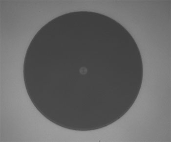
Figure G1.1 PANDA PM Fiber Cross Section
- Pure Silica Core for Resistance to Photodarkening
- PANDA Stress Members
- Operating Wavelength Ranges Span from 350 to 680 nm
These pure silica core polarization-maintaining fibers are designed for wavelengths from 350 to 680 nm. Their pure silica core provides protection from photodarkening, which makes them ideal for use at short wavelengths. These fibers use PANDA-type stress rods for polarization-maintaining operation.
| Item # | Wavelength Range |
MFDa | NAb | Core Index |
Cladding Index |
Cut-Off | Attenuation | Beat Length |
Cladding Diameter |
Coating Diameter |
Strip Tool |
|---|---|---|---|---|---|---|---|---|---|---|---|
| PM-S350-HP | 350 - 460 nm | 2.3 µm @ 350 nm |
0.12 | Callc | Callc | ≤340 nm | - | 1.5 mm @ 350 nm |
125 ± 2 µm | 245 ± 15 µm | T06S13 |
| PM-405 | 400 - 488 nm | 3.5 ± 0.5 µm @ 410 nm |
0.09 | 365 ± 35 nm | ≤50.0 dB/km @ 410 nm |
≤1.7 mm @ 410 nm |
|||||
| PM-S405-XP | 400 - 680 nm | 3.3 ± 0.5 µm @ 405 nm 4.6 ± 0.5 µm @ 630 nm |
0.12 | 380 ± 20 nm | ≤30.0 dB/km @ 488 nm ≤30.0 dB/km @ 630 nm |
2.0 mm @ 405 nm |

 Zoom
ZoomClick for Details
Figure G2.1 PANDA PM Fiber Cross Section
- Operating Wavelength Ranges Span from 460 to 2200 nm
- PANDA Stress Members
These polarization-maintaining fibers are designed for single-mode transmission in the visible, NIR, and telecom wavelength ranges. They have PANDA-type stress rods for polarization-maintaining operation.
| Item # | Wavelength Range |
MFDa | NAb | Core Index |
Cladding Index |
Cut-Off | Attenuation | Beat Length |
Cladding Diameter |
Coating Diameter |
Strip Tool |
|---|---|---|---|---|---|---|---|---|---|---|---|
| PM460-HP | 460 - 700 nm | 3.3 ± 0.5 µm @ 515 nm |
0.12 | Callc | Callc | 410 ± 40 nm | ≤100 dB/km @ 488 nm |
1.3 mm @ 460 nm |
125 ± 2 µm | 245 ± 15 µm | T06S13 |
| PM630-HP | 620 - 850 nm | 4.5 ± 0.5 µm @ 630 nm |
570 ± 50 nm | ≤15 dB/km @ 630 nm |
1.8 mm @ 630 nm |
||||||
| PM780-HP | 770 - 1100 nm | 5.3 ± 1.0 µm @ 850 nm |
710 ± 60 nm | ≤4 dB/km @ 850 nm |
2.4 mm @ 850 nm |
||||||
| PM980-XP | 970 - 1550 nm | 6.6 ± 0.5 µm @ 980 nm |
920 ± 50 nm | ≤2.5 dB/km @ 980 nm |
≤2.7 mm @ 980 nm |
||||||
| PM1300-XP | 1270 - 1625 nm | 9.3 ± 0.5 µm @ 1300 nm |
1210 ± 60 nm | ≤1.0 dB/km @ 1300 nm |
≤4.0 mm @ 1300 nm |
||||||
| PM1550-XP | 1440 - 1625 nm | 10.1 ± 0.4 µm @ 1550 nm |
0.125 | 1380 ± 60 nm | <1.0 dB/km @ 1550 nm |
≤5.0 mm @ 1550 nm |
|||||
| PM2000 | 1850 - 2200 nm | 8.0 µm @ 1950 nm |
0.20 | 1720 ± 80 nm | <11.5 dB/km @ 1950 nm <22.5 dB/km @ 2000 nm |
5.2 mm @ 1950 nm |

 Zoom
ZoomClick for Details
Figure G3.1 PANDA PM Fiber Cross Section
Applications
- Grating-Based Pump Diode Pigtails
- Sensors
- Multiplexers
Features
- Typical PM Fiber Performance with Added Photosensitivity
- PANDA Stress Members
- High Photosensitivity
- High Lot-to-Lot Uniformity
PS-PM980 photosensitive 970 - 1550 nm polarization maintaining fiber is designed to perform all functions of a 980 nm PM fiber but with enhanced photosensitivity for fabrication of gratings. Portions of this fiber that are exposed to UV light will have their refractive index changed, thus allowing the construction of a Fiber Bragg Grating or other types of devices with periodic changes in refractive index.
This fiber is designed for use in 980 nm pump diodes, couplers and multiplexers. Using one fiber that provides excellent photosensitivity, as well as polarization maintaining attributes, substantially reduces writing time thus lowering costs.
| Item # | Operating Wavelength |
MFD | NA | Core Index | Cladding Index | Cut-Off Wavelength |
Attenuation | Cladding Diameter |
Coating Diameter |
Strip Tool |
|---|---|---|---|---|---|---|---|---|---|---|
| PS-PM980 | 970 - 1550 nm | 6.6 ± 1.0 µm @ 980 nm | 0.12 | Calla | Calla | 900 ± 70 nm | ≤3.0 dB/km @ 980 nm | 125 ± 1.0 µm | 245 ± 15 µm | T06S13 |
Click for Details
Figure G4.1 PANDA PM Fiber Cross Section

Features
- -100 ± 10 ps/(nm•km) Dispersion at 1550 nm
- -0.34 ps/(nm2•km) Dispersion Slope at 1550 nm
- Dispersion and Dispersion Slope Matched to Standard PM 1550 nm Fibers
- Optimized for Slow-Axis Light Propagation
Applications
- Pulse-Stretching or Pulse-Compression Fiber
- Optical Timing Distribution Systems
- Telecommunications
Thorlab’s PMDCF Dispersion-Compensating fibers (DCF) corrects for both the chromatic dispersion and dispersion slope of standard PM optical fiber in the 1510 to 1620 nm wavelength range. Sub-picosecond pulses are transmitted with low loss and no pulse broadening caused by chromatic dispersion, all while maintaining linear polarization. The fiber has PANDA stress rod supports that run parallel to the fiber's core and apply stress that creates a birefringence in the fiber's core which enables polarization-maintaining operation, and is specially designed for slow-axis light propagation.
| Item # | Operating Wavelength |
MFD | NA | Core Index | Cladding Index | Cut-Off Wavelength, Slow-Axis |
Attenuation | Cladding Diameter |
Coating Diameter |
Strip Tool |
|---|---|---|---|---|---|---|---|---|---|---|
| PMDCF | 1510 - 1620 nm | 5 µm @ 1550 nm | Proprietarya | Callb | Callb | 1400 nm | 0.40 dB/km (Typ.) @1550 nm 0.45 dB/km (Max) @1550 nm |
125 ± 1.5 µm | 250 ± 10 µm | T06S13 |

 Zoom
Zoom
Click for Details
Figure G5.1 Bow-Tie PM Fiber Cross Section
- Operating Wavelength Ranges Span from 980 to 1310 nm
- Bow-Tie Stress Members
These polarization-maintaining fibers use bow-tie stress members. They are commonly used for sensor applications, polarization multiplexing of EDFA lasers, and laser pigtailing.
| Item # | Design Wavelengtha |
MFDb | NA | Core Indexc |
Cladding Indexc |
Cut-Off | Attenuationd | Beat Lengthe |
Cladding Diameter |
Coating Diameter |
Strip Tool |
|---|---|---|---|---|---|---|---|---|---|---|---|
| HB980T | 980 nm | 5.3 - 6.4 µm | 0.13 - 0.15 | 980 nm: 1.45647f | 980 nm: 1.45068f | 870 - 970 nm | ≤3 dB/km | ≤2.0 mm | 125 ± 1 µm | 245 ± 15 µm | T06S13 |
| HB1250T | 1310 nm | 8.1 - 9.9 µm | 0.11 - 0.13 | 1310 nm: 1.45094g | 1310 nm: 1.44680g | 1100 - 1290 nm | <2 dB/km | <2.0 mm | 125 ± 1 µm | 400 µm ± 5% | T06S16 |

 Zoom
ZoomClick for Details
Figure G6.1 Bow-Tie PM Fiber Cross Section
- Optimized for Bend- and Temperature-Resistance Performance
- Ideal for Fiber Optic Gyroscope (FOG) Applications
- Bow-Tie Stress Members
This polarization-maintaining fiber is optimized for fiber optic gyroscope (FOG) applications. It is designed for optimal performance over a wide temperature range and with a small coil radius. Extinction ratios of 29.5 dB at -40 °C and 28.5 dB at -60 °C are typical for this fiber.
| Item # | Design Wavelengtha |
MFDb | NA | Core Indexc | Cladding Indexc | Cut-Off | Attenuationd | Beat Lengthe |
Cladding Diameter |
Coating Diameter |
Strip Tool |
|---|---|---|---|---|---|---|---|---|---|---|---|
| HB800G | 830 nm | 3.7 - 4.9 µm | 0.14 - 0.18 | 830 nm: 1.45954f | 830 nm: 1.45282f | 660 - 800 nm | ≤5 dB/km | ≤1.5 mm | 80 ± 1 µm | 165 ± 10 µm | T04S10 |