

Fiber Optic Power Meters with Internal Sensor
- Wavelength Ranges: 400 nm to 1700 nm
- Power Ranges: -70 dBm to 23 dBm
- Interchangeable Fiber Connector
- Options Available for Integrated Visual Fault Locator
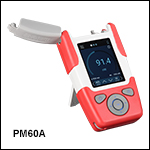
PM60A
Fiber Optic Power Meter
400 - 1100 nm
Easy-to-Read Large
Digital Touchscreen Display
PM61 Series Power Meter with Included Fiber Adapter Removed
Additional SM05-Threaded Fiber Adapters Available Separately
PM20-SMA
PM20-ST
OVERVIEW
| PM60 and PM61 Series Features | ||
|---|---|---|
| Item # | PM60 Series | PM61 Series |
| Rechargeable Battery |  |
|
| Fast Charging vis USB-C Connector | |
|
| Embedded Wireless Charging Coil | - | |
| Data Storage to Internal Flash Memory | |
|
| Internal Flash Memory Access via USB | |
|
| Pass / Fail Analysis | - | |
| Admin / User Levels | - | |
| Physical Menu Button Configuration | - | |
| Visual Fault Locator (VFL) | - | |
| USB 2.0 Full Speed Interface | |
|
| Bluetooth Low Energy Connectivity | - | |
| OPM Software Compatible | |
|
Click to Enlarge
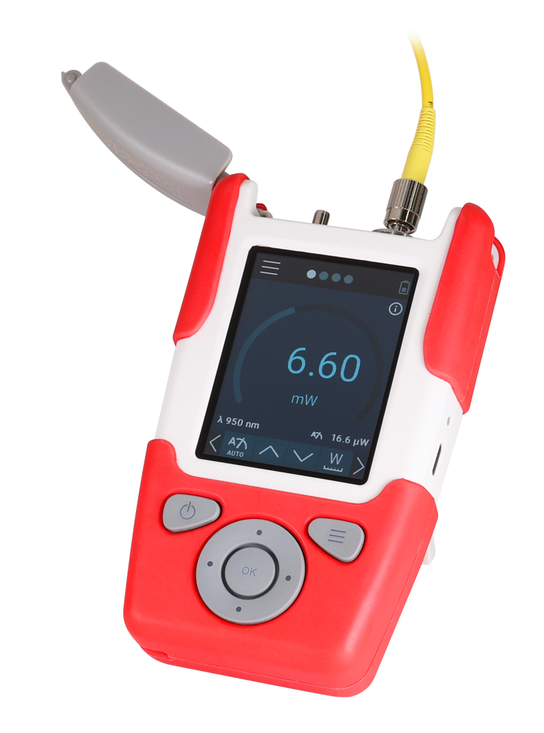
Figure 1.1 A PM61CH power meter with a fiber-optic patch cable (sold separately) attached to the detector port is shown here.
| Power Meter Selection Guide |
|---|
| Sensors |
| Photodiode Power Sensors |
| Thermal Power Sensors |
| Thermal Position & Power Sensors |
| Pyroelectric Energy Sensors |
| Power Meter Consoles and Interfaces |
| Digital Handheld Console |
| Analog Handheld Console |
| Touchscreen Handheld Console |
| Dual-Channel Benchtop Console |
| USB Interfaces with External Readout |
| Complete Power Meters |
| Power Meter Bundles |
| Wireless Power Meters with Sensors |
| Compact USB Power Meters |
| Field Power Meters for Terminated Fibers |
Fiber Optic Power Meter Features
- Si (PM6xA) or InGaAs (PM6xC or PM6xCH) Sensors
- Wavelength Range:
- 400 nm - 1100 nm (Si)
- 800 nm - 1700 nm (InGaAs)
- Power Ranges:
- -65 dBm to 16 dBm (300 pW - 40 mW) for PM6xA
- -70 dBm to 13 dBm (100 pW - 20 mW) for PM6xC
- -55 dBm to 23 dBm (3 nW - 200 mW) for PM6xCH
- Interchangeable Fiber Connectors:
- PM20-25 2.5 mm Ferrule Adapter Included
- FC/PC, FC/APC, SC, ST®, LC, or SMA Adapters Sold Separately Below
- Absolute and Relative Measurements Displayed in dBm, dB, pW, nW, µW, mW, and W
- NIST- and PTB-Traceable Wavelength Calibration
- Digital Menu Navigation via Physical Buttons and Capacitive Touchscreen
- Support for Remote Operation
The PM60 and PM61 Series of Fiber Optic Power Meters are robust, full-featured, handheld instruments, which together cover the full range of optical fiber applications within the 400 - 1700 nm range with optical powers ranging from -70 dBm to +23 dBm (100 pW - 200 mW). A rugged enclosure, internal sensors, kickstand, and hand strap eyelet (hand strap not included) make these models ideal for field or lab applications. The PM60A and PM61A power meters use a Si sensor for detection between 400 nm and 1100 nm, while the PM60C, PM60CH, PM61C, and PM61CH use an InGaAs sensor for detection between 800 nm to 1700 nm.
Each unit is shipped with a PM60 or PM61 series power meter with an attached PM20-25 fiber adapter, USB cable (Type A to Type C), Certificate of Calibration, and Quick Reference.
Device Design
The PM60 and PM61 series power meters can be operated using both a 2.8" capacitive touchscreen and the physical keys shown in Figure 1.1. An interactive GUI is available to demo all the features (click here or see the Interactive Demo tab). Each power meter comes with a USB C rechargeable, lithium polymer (LiPo) battery with a 2300 mAh capacity. The PM61 series power meters feature an additional wireless charging capability via an inductive charging coil. Each power meter is shipped with an SM05 (0.535"-40) internally threaded PM20-25 adapter for fiber patch cables with 2.5 mm ferrules. The PM20-25 adapter is designed without a locking mechanism to allow for fast and efficient power measurements using patch cables with a variety of terminations.
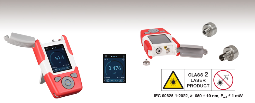
The PM61 series power meters are equipped with a Visual Fault Locator (VFL) consisting of a 650 nm class 2 guide laser and 2.5 mm ferrule receptacle which can be used to find fibers in a bundle, breaks in a fiber, or alignment into an optical fiber. The VFL can be used in a continuous wave (CW), 1 Hz flashing, or 3 Hz flashing setting.
Remote Operation
The PM60 and PM61 series power meters can be controlled remotely using Thorlabs' Optical Power Monitor (OPM) software. Both series feature a USB 2.0 interface to connect to a PC. Additionally, the PM61 series has a built in Bluetooth module that allows the user to establish a wireless connection to a PC. Remote connectivity allows the user to access the power meter settings, visualize power measurements, and record data directly through the OPM software. Please see the Software tab for details.
Analysis Tools
The Fiber Power Meter Series offer Data Logging and Statistics analysis tools which allow for power levels over a specified time period to be recorded and saved on the internal memory to be accessed at a later time using the USB connection and an external PC. The Data Logging tool shows a time trace of the power levels over the given interval while the Statistics tool shows the number of samples, elapsed time and mean, maximum, and minimum power levels. The PM61 series also features the Pass / Fail Analysis tool which gives a visual indication to whether a given measurement is within a predefined power range.
*ST® is a registered trademark of Lucent Technologies, Inc.
SPECS
| Item #a | PM60A, PM61A | PM60C, PM61C | PM60CH, PM61CH |
|---|---|---|---|
| Sensor Specifications | |||
| Optical Power Range | -65 dBm to 16 dBm (300 pW - 40 mW) |
-70 dBm to 13 dBm (100 pW - 20 mW) |
-55 dBm to 23 dBm (3 nW - 200 mW) |
| Spectral Range | 400 - 1100 nm | 800 - 1700 nm | |
| Detector Type | Silicon | InGaAs | |
| Sensor Size | 3.6 x 3.6 mm | Ø3 mm | |
| Aperture Thread | SM05 Thread (0.535"-40) for Fiber Adapters 2.5 mm Ferrule Adapter Included (Item # PM20-25) |
||
| Measurement Uncertainty | ±0.25 dB | ||
| Measurement Standard | NIST / PTB Traceable | ||
| General Device Specifications | |||
| Display Type | 2.8" IPS with Capacitive Touchscreen | ||
| Power Ranges | 21 Current Ranges from 2 nA to 10 mA, Represented in Watts | ||
| Power Units | dBm, dB, pW nW, µW, mW, W | ||
| Resolution | 16 bits | ||
| Sample Rate | Up to 100 kS/s via USB | ||
| Dimensions (H x W x D) w/ Holster | 136.0 mm x 79.0 mm x 34.4 mm (5.35" x 3.11" x 1.32") |
||
| Weight | 0.25 kg (0.55 lbs) | ||
| Operating Temperature | 5 °C to 40 °C | ||
| Storage Temperature | -20 °C to 70 °C | ||
| Power Management | |||
| Battery Operation | Internal LiPo Battery Pack, 2300 mAh, 3.7 W | ||
| Charger | USB C, Inductive Charging Coil (PM61 Series Only), 5 W | ||
| Remote Operation | |||
| Interface | USB 2.0 with USB Type C Connector Bluetooth Low Energy (PM61 Series Only) |
||
| Data Storage | |||
| Internal Memory | eMMC (≥4 GB), Accessible via USB C | ||
| Visual Fault Locator (PM61 Series Only) | |||
| Wavelength | 650 nm | ||
| Output Power | ≤1 mW (Class 2 Laser) | ||
| Operation | CW, Flashing: 1 Hz, 3 Hz | ||
| Connector | 2.5 mm Ferrule | ||
INTERACTIVE DEMO

Interactive Demo
An interactive GUI is available in this tab to demo all the features of the PM60 and PM61 Series Power Meters. A full-screen demo is also available by clicking the Full-Screen PM60 / PM61 Demo button. For computers with a touchscreen, the demo supports all swipe gestures to switch screens. Otherwise, a mouse or directional and enter keys can be used to interact with these functions. The GUI provides the opportunity to browse all submenus and change settings. For information on navigating the measurement and menu screens, please see the PM60 and PM61 Series Power Meter manual.
The demo offers access to all the features of the PM60 or PM61 Series Power Meters that are selectable while using either the touchscreen or the physical keypad with limited configurability. The simulated measured power level can be set over several decades and simulated measurements can be performed displaying as it would on the physical device.
SOFTWARE
Compatible Power Meters
- Consoles:
- PM100A Analog Power and Energy Meter Console
- PM200 Legacy Touch Screen Power and Energy Meter Console
- PM100D Digital Power and Energy Meter Console
- PM400 Capacitive Touchscreen Power and Energy Meter Console
- PM5020 Dual-Channel Benchtop Optical Power and Energy Meter Console (Version 4.0 or Later)
- Complete Power Meters:
- PM160, PM160T, and PM160T-HP Wireless Handheld Power Meters with Bluetooth® Technology
- PM16 Series Compact USB Power Meters
- PM60 and PM61 Fiber Optic Power Meter Series (Version 6.0 or Later)
- Interfaces:
- PM101 Series Power Meter Interfaces with External Readout (Version 2.0 or Later)
- PM102 Series Power Meter Interfaces with External Readout (Version 2.1 or Later)
- PM103 Series Power Meter Interfaces with External Readout (Version 3.0 or Later)
- PM100USB USB Interface Digital Power and Energy Meter
Other Compatible Devices
- ERM2xx Series Extinction Ratio Meters
- SPCNT Single Photon Counting Device
- TSP01 USB Temperature and Humidity Data Logger
- TSP-TH Additional Temperature Probe
- WM202 Wavelength Meter
Optical Power Monitor
The Optical Power Monitor GUI software features readout from up to eight power meters or other compatible devices, or remote wireless operation.
For details on specific software features, please see the user manual.
Users interested in the legacy Power Meter Software can find it by visiting the software page.
The PM101 Series Power Meters are only compatible with version 2.0 or later. The PM102 Series Power Meters are only compatible with version 2.1 or later. The PM103 Series Power and Energy Meters are only compatible with version 3.0 or later. The PM5020 Console is only compatible with version 4.0 or later. The PM60 and PM61 Power Meter Series are only compatible with version 6.0 or later.
Optical Power Monitor GUI Software for Touchscreen, Handheld, and USB-Interface Power Meters
Features
- Operate up to Eight Devices Simultaneously
- Record and Analyze Measurements in Real Time
- Intuitive Analog Display and Graphing Modes
- Configurable Long-Term Data Logging
- Also Supports Position Measurements with Thermal Position & Power Sensors
- Compatible with USB and Bluetooth® Connections
The Optical Power Monitor (OPM) software GUI enables seamless control of up to eight compatible devices that are connected via USB, RS232, or Bluetooth® wireless technologya. The latest software, firmware, drivers, and utilities for these power meters can be downloaded here.
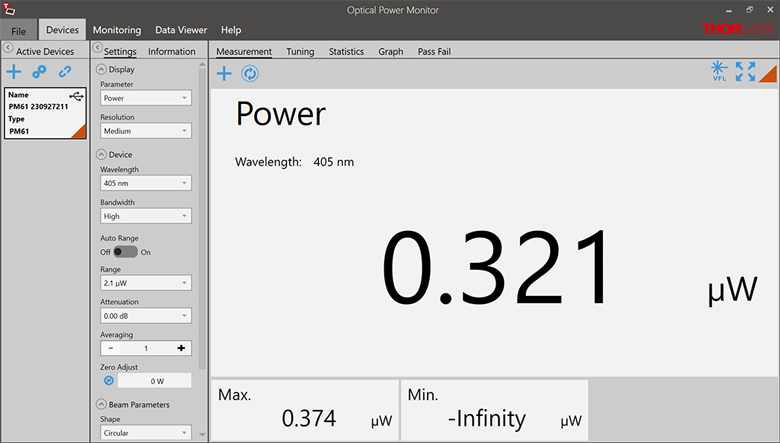
Multiple data measurement and analysis functions are integrated into the GUI package. The interface offers a user-friendly design with minimal use of color and low brightness that is ideal for use in dark lab environments while wearing laser safety glasses. Measured data can be displayed in real time as a simulated analog needle, digital values, line graph, or bar graph. Continuously logged and short-term measurements can be recorded for data viewing and analysis at a later point. A built-in statistics mode analyzes measured data and updates continuously to reflect new measurements within the pre-determined measurement period. Beam position measurements are also supported when used with our thermal position & power sensors.
The OPM software package installs the GUI, which then can be used to control the touchscreen, handheld, or USB-interface power meters and other compatible devices. Firmware updates for supported power meters are also available. Programming examples and drivers for interfacing with our power and energy meter consoles using LabVIEW, C/C++, Visual C#, and Python are installed with the software; refer to the manual for details.
Please note that the OPM Software uses different drivers than the Power Meter Utilities Software and Thorlabs recommends using the new driver TLPM.dll. For users who wish to use the legacy Power Meter Software or use custom software designed using the older PM100D.dll driver, a Power Meter Driver Switcher program is included for easy swapping of the installed driver between the two versions.
a. The PM61 Series, PM160, PM160T, and PM160T-HP power meters are equipped with Bluetooth® connections.

Click to Enlarge
Figure 149B Power Tuning Mode
Simulated analog needle and digital measurement value provided. Delta Mode, enabled here, shows the fluctuation range during the measurement period.
Click to Enlarge
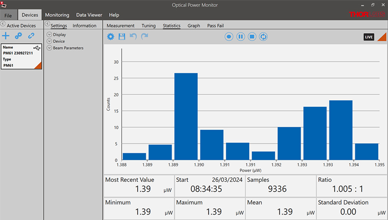
Figure 149C Power Statistics Mode
Calculate numerical statistics for a pre-determined measurement period. The panel displays the analyzed values in a bar graph and the results as numerical values.
Click to Enlarge
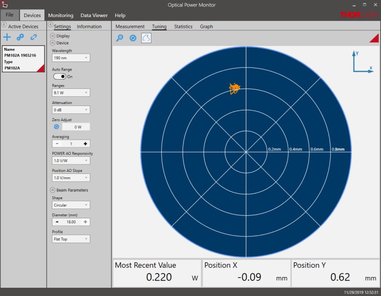
Figure 149D Position Tuning Mode
Tuning mode can be used with a thermal position & power sensor to aid in beam alignment.
Click to Enlarge
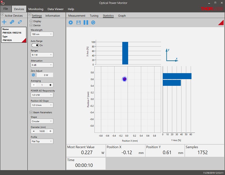
Figure 149E Position Statistics Mode
Statistics mode also provides aggregate information for thermal position & power sensors.
Click to Enlarge
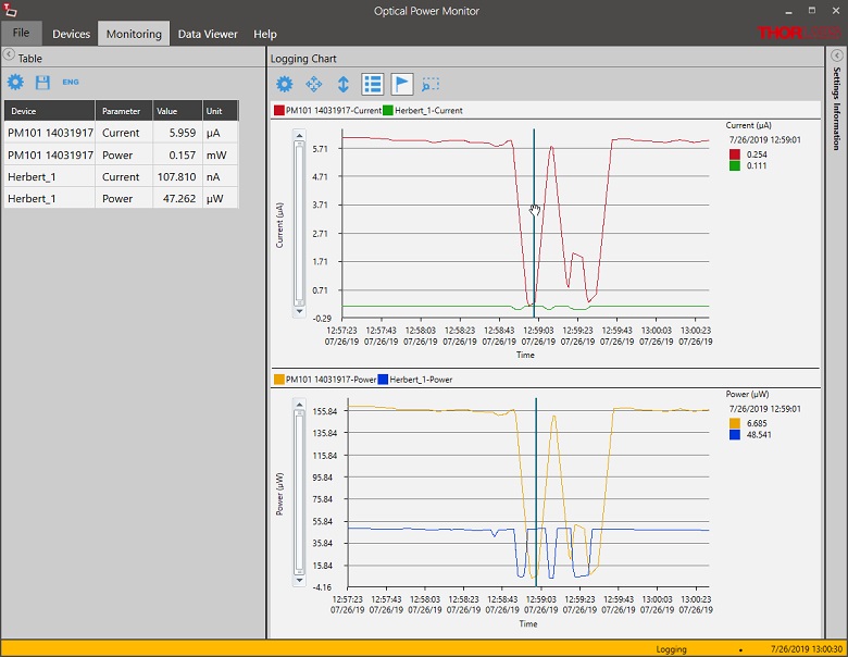
Figure 149F Data Logging
Enable long-term measurement and simultaneous recording from up to eight power meters. Save data as .csv files for later processing while measurement results are displayed in a graph in real time.
PULSE CALCULATIONS
Pulsed Laser Emission: Power and Energy Calculations

Determining whether emission from a pulsed laser is compatible with a device or application can require referencing parameters that are not supplied by the laser's manufacturer. When this is the case, the necessary parameters can typically be calculated from the available information. Calculating peak pulse power, average power, pulse energy, and related parameters can be necessary to achieve desired outcomes including:
- Protecting biological samples from harm.
- Measuring the pulsed laser emission without damaging photodetectors and other sensors.
- Exciting fluorescence and non-linear effects in materials.
Pulsed laser radiation parameters are illustrated in Figure 170A and described in Table 170B. For quick reference, a list of equations is provided below. The document available for download provides this information, as well as an introduction to pulsed laser emission, an overview of relationships among the different parameters, and guidance for applying the calculations.
|
Equations: |
||||
 |
and |  |
||
 |
||||
 |
||||
 |
||||
Peak power and average power calculated from each other: |
||||
 |
and |  |
||
| Peak power calculated from average power and duty cycle*: | ||||
 |
*Duty cycle ( ) is the fraction of time during which there is laser pulse emission. ) is the fraction of time during which there is laser pulse emission. |
|||
Click to Enlarge
Figure 170A Parameters used to describe pulsed laser emission are indicated in this plot and described in Table 170B. Pulse energy (E) is the shaded area under the pulse curve. Pulse energy is, equivalently, the area of the diagonally hashed region.
| Table 170B Pulse Parameters | |||||
|---|---|---|---|---|---|
| Parameter | Symbol | Units | Description | ||
| Pulse Energy | E | Joules [J] | A measure of one pulse's total emission, which is the only light emitted by the laser over the entire period. The pulse energy equals the shaded area, which is equivalent to the area covered by diagonal hash marks. | ||
| Period | Δt | Seconds [s] | The amount of time between the start of one pulse and the start of the next. | ||
| Average Power | Pavg | Watts [W] | The height on the optical power axis, if the energy emitted by the pulse were uniformly spread over the entire period. | ||
| Instantaneous Power | P | Watts [W] | The optical power at a single, specific point in time. | ||
| Peak Power | Ppeak | Watts [W] | The maximum instantaneous optical power output by the laser. | ||
| Pulse Width |  |
Seconds [s] | A measure of the time between the beginning and end of the pulse, typically based on the full width half maximum (FWHM) of the pulse shape. Also called pulse duration. | ||
| Repetition Rate | frep | Hertz [Hz] | The frequency with which pulses are emitted. Equal to the reciprocal of the period. | ||
Example Calculation:
Is it safe to use a detector with a specified maximum peak optical input power of 75 mW to measure the following pulsed laser emission?
- Average Power: 1 mW
- Repetition Rate: 85 MHz
- Pulse Width: 10 fs
The energy per pulse:

seems low, but the peak pulse power is:

It is not safe to use the detector to measure this pulsed laser emission, since the peak power of the pulses is >5 orders of magnitude higher than the detector's maximum peak optical input power.
Fiber Optic Power Meters with Internal Sensor
- Handheld Fiber Optic Power Meter for Wavelength Ranges Between 400 - 1700 nm
- 2300 mAh Battery with USB C Charging Cable Included
- Remote Operation Using USB 2.0 Interface
- Internal Data Storage and Access via USB
The PM60 Series Fiber Optic Power Meters are robust, handheld instruments that are ideal for both lab and field applications. Each unit includes a rechargeable 2300 mAh LiPo battery that has the capacity for continuous operation throughout a workday.
The PM60A power meter features an internal Si sensor for measuring wavelengths from 400 nm to 1100 nm at optical powers from -65 dBm to +16 dBm (300 pW - 40 mW). The PM60C and PM60CH power meters both feature an InGaAs sensor for measuring wavelengths from 800 - 1700 nm and are sensitive to optical powers from -70 dBm to +13 dBm (100 pW - 20 mW) and -55 dBm to +23 dBm (3 nW - 200 mW), respectively.
Part Number | Description | Price | Availability |
|---|---|---|---|
PM60A | Fiber Optic Power Meter, 400 - 1100 nm, -65 dBm to 16 dBm (300 pW to 40 mW) | $802.50 | Today |
PM60C | Fiber Optic Power Meter, 800 - 1700 nm, -70 dBm to 13 dBm (100 pW to 20 mW) | $930.90 | Lead Time |
PM60CH | Fiber Optic Power Meter, 800 - 1700 nm, -55 dBm to 23 dBm (3 nW to 200 mW) | $1,005.80 | In Stock Overseas |
Fiber Optic Power Meter with Internal Sensor and Visual Fault Locator
- Handheld Fiber Optic Power Meter for Wavelength Ranges Between 400 - 1700 nm
- Built-In 650 nm Visual Fault Locator (VFL) Included
- 2300 mAh Battery with USB C Cable and Wireless Charging Included
- Remote Operation Using USB 2.0 or Bluetooth Interface
- Internal Data Storage and Access via USB
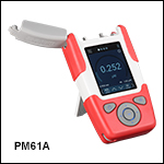
The PM61 Series Fiber Optic Power Meters are robust, handheld instruments that are ideal for both lab and field applications. Each unit includes a rechargeable 2300 mAh LiPo battery that has the capacity for continuous operation throughout a workday.
The PM61A power meter features an internal Si sensor for measuring wavelengths from 400 nm to 1100 nm at optical powers from -65 dBm to +16 dBm (300 pW - 40 mW). The PM61C and PM61CH power meters both feature an InGaAs sensor for measuring wavelengths from 800 - 1700 nm and are sensitive to optical powers from -70 dBm to +13 dBm (100 pW - 20 mW) and -55 dBm to +23 dBm (3 nW - 200 mW), respectively.
Each PM61 series fiber optic power meter contains an integrated VFL that emits ≤1 mW at 650 nm and can be used for detecting fibers in a bundle, breaks in an optical fiber, or aid in free-space to fiber alignment. The VFL can be operated in CW, Flashing: 1 Hz, or 3 Hz modes via the touchscreen or physical buttons on the device, or using the OPM software GUI.
Additionally, the PM61 series features user configurable menus along with Admin / User levels to ensure operation is customizable and secure for all users.
Part Number | Description | Price | Availability |
|---|---|---|---|
PM61A | Fiber Optic Power Meter with Visual Fault Locator, 400 - 1100 nm, -65 dBm to 16 dBm (300 pW to 40 mW) | $1,134.20 | Today |
PM61C | Fiber Optic Power Meter with Visual Fault Locator, 800 - 1700 nm, -70 dBm to 13 dBm (100 pW to 20 mW) | $1,262.60 | Today |
PM61CH | Fiber Optic Power Meter with Visual Fault Locator, 800 - 1700 nm, -55 dBm to 23 dBm (3 nw to 200 mW) | $1,337.50 | Today |
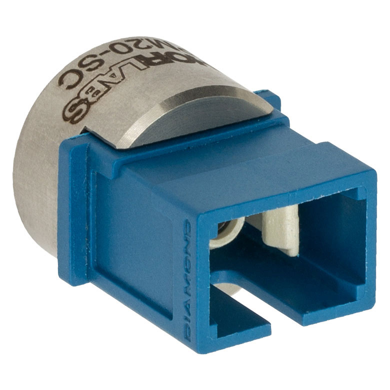
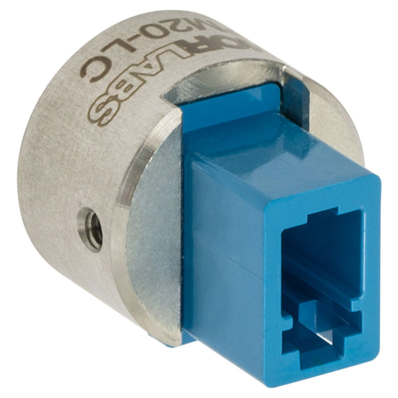
Fiber and Ferrule Adapters for PM60x and PM61x Power Meters
These adapters are compatible with devices that feature external SM05 threading such as our S15xC Series Fiber Power Meter Sensors, PM160 wireless power meter, and the Fiber Optic Power Meters above. One PM20-25 wide-key FC/PC fiber adapter is included with each of the power meters sold above. For details on narrow versus wide key connectors, please see our Intro to Fiber tutorial.
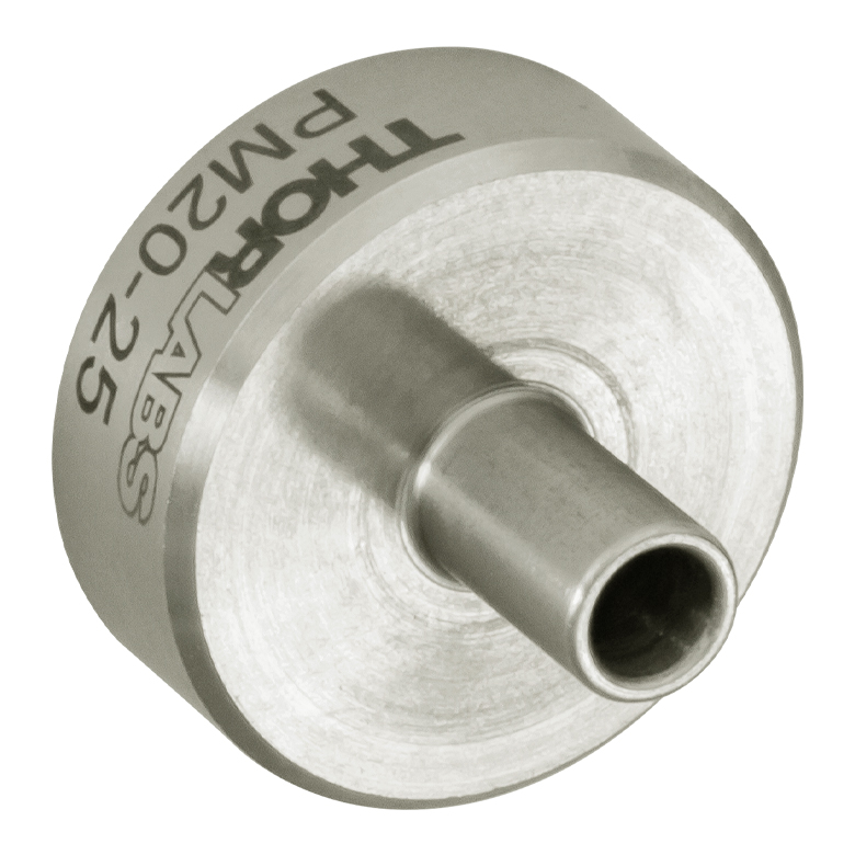
The PM20-25 ferrule adapter is designed without a locking connector mechanism and accepts fiber patch cables with Ø2.5 mm ferrules for quick power meter measurements.
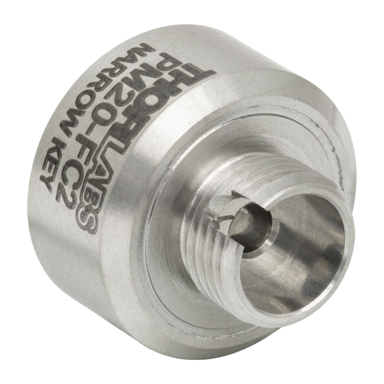
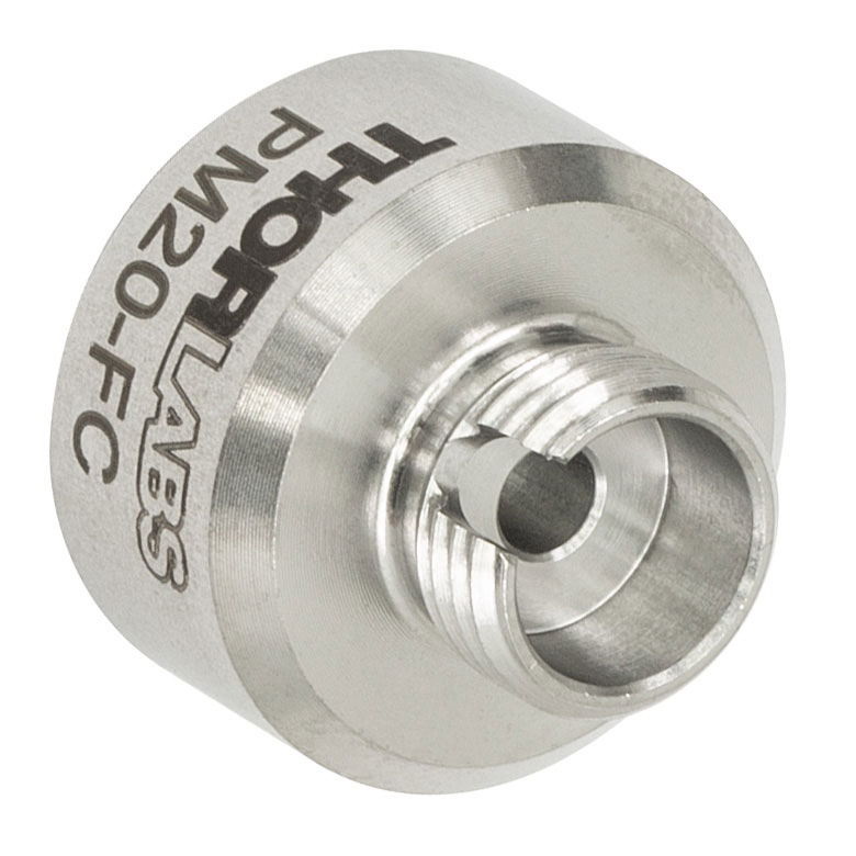
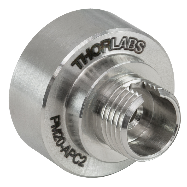
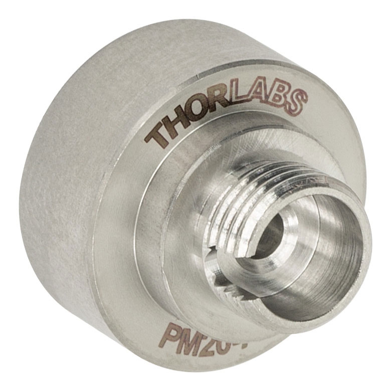
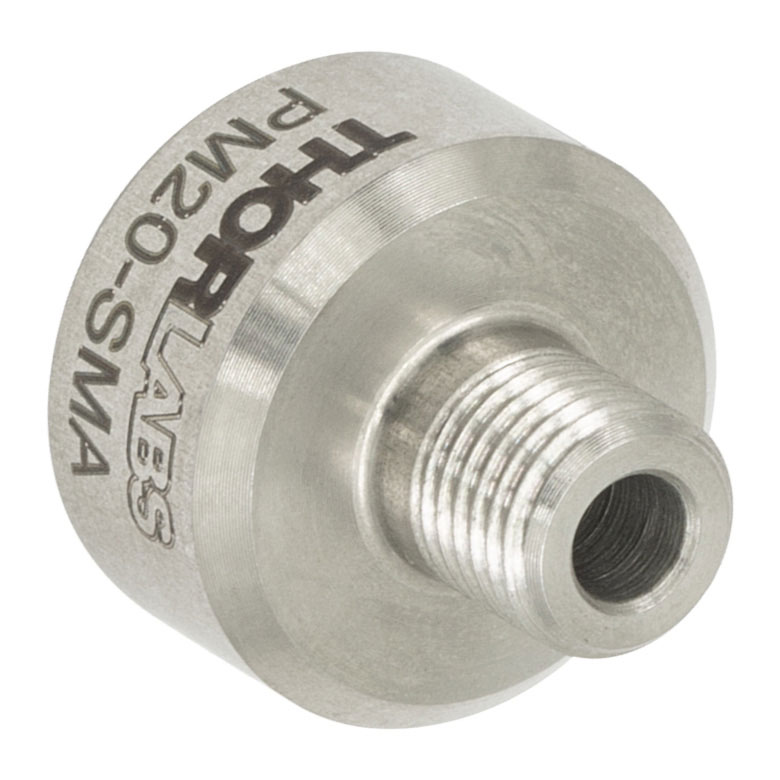
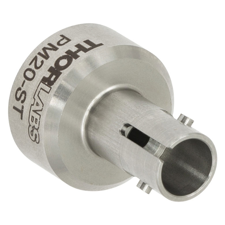
| Item # | PM20-FC2 | PM20-FC | PM20-APC2a | PM20-APCa | PM20-SMA | PM20-ST | PM20-SC | PM20-LC | PM20-25 |
|---|---|---|---|---|---|---|---|---|---|
| Adapter Image (Click the Image to Enlarge) |
 |
 |
 |
 |
 |
 |
 |
 |
 |
| Connector Type | FC/PC, 2.0 mm Narrow Key |
FC/PC, 2.2 mm Wide Key |
FC/APC, 2.0 mm Narrow Key |
FC/APC, 2.2 mm Wide Key |
SMA | ST®b/PC | SC/PCc | LC/PC | Ø2.5 mm Ferrule |
| Threading | Internal SM05 (0.535"-40) | ||||||||
Part Number | Description | Price | Availability |
|---|---|---|---|
PM20-FC2 | FC/PC Fiber Adapter Cap with Internal SM05 (0.535"-40) Threads, Narrow Key (2.0 mm) | $40.36 | Today |
PM20-FC | FC/PC Fiber Adapter Cap with Internal SM05 (0.535"-40) Threads, Wide Key (2.2 mm) | $40.36 | Today |
PM20-APC2 | FC/APC Fiber Adapter Cap with Internal SM05 (0.535"-40) Threads, Narrow Key (2.0 mm) | $39.88 | Today |
PM20-APC | Customer Inspired! FC/APC Fiber Adapter Cap with Internal SM05 (0.535"-40) Threads, Wide Key (2.2 mm) | $39.88 | Today |
PM20-SMA | SMA Fiber Adapter Cap with Internal SM05 (0.535"-40) Threads | $40.36 | Today |
PM20-ST | ST/PC Fiber Adapter Cap with Internal SM05 (0.535"-40) Threads | $55.94 | Today |
PM20-SC | SC/PC Fiber Adapter Cap with Internal SM05 (0.535"-40) Threads | $55.94 | Today |
PM20-LC | Customer Inspired! LC/PC Fiber Adapter Cap with Internal SM05 (0.535"-40) Threads | $55.94 | Today |
PM20-25 | Customer Inspired! Ø2.5 mm Ferrule Adapter Cap with Internal SM05 (0.535"-40) Threads | $40.36 | Today |