 Products Home / Optical Elements / Optical Filters / Spatial Filters / Pinhole Spatial Filter System
Pinhole Spatial Filter System
- Produces "Clean" Gaussian Beams
- Easy-to-Follow Instructions and Alignment Tools Included
Application Idea
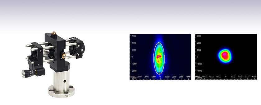
The KT311(/M) spatial filter system can be used to circularize an elliptical beam from a collimated laser source. For more information, please see the Lab Facts tab.
Collimated Output Source
Output After Spatial Filter
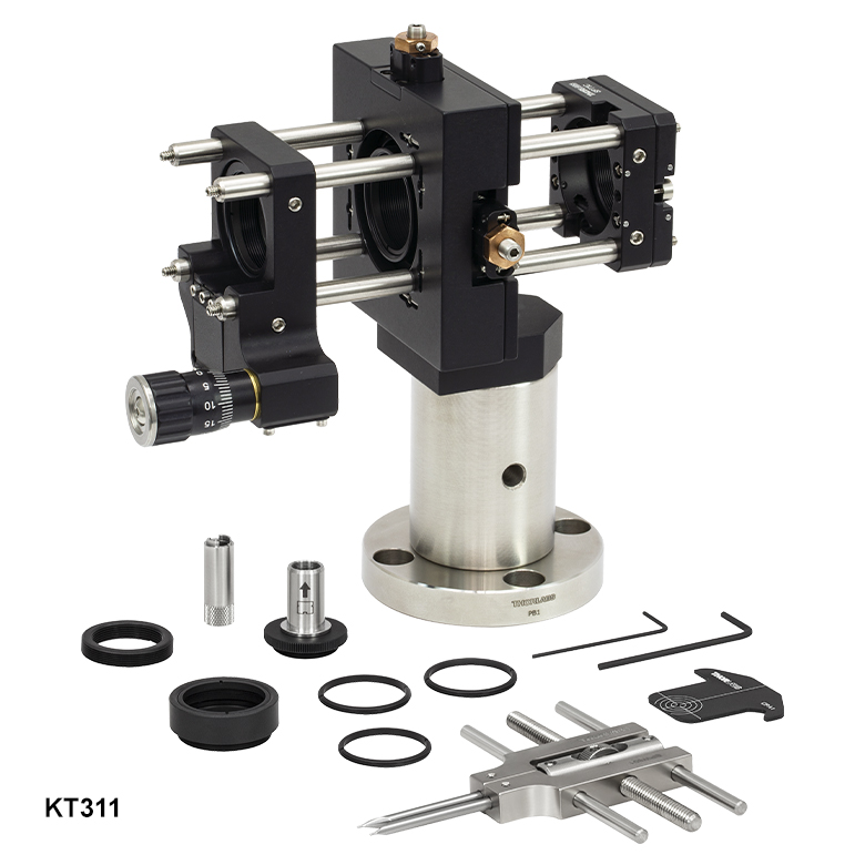
KT311
Spatial Filter System


Please Wait
| Apertures Selection Guide |
|---|
| Single Precision Pinholes |
| Circular in Stainless Steel Foils |
| Circular in Stainless Steel Foils, Vacuum Compatible |
| Circular in Gold-Plated Copper Foils |
| Circular in Tungsten Foils |
| Circular in Molybdenum Foils |
| Square in Stainless Steel Foils |
| Pinhole Kits |
| Pinhole Wheels |
| Manual |
| Motorized |
| Pinhole Spatial Filter |
| Slits |
| Annular Apertures |
| Alignment Tools |
Features
- Produces a Clean Gaussian Beam
- Compatible with a Wide Assortment of Pinholes, Aspheric Lenses, and Collimating Lenses
- Pre-Assembled System of Stock Catalog Components
- Optics and Pinhole Not Included
The KT311(/M) spatial filter system is ideal for producing a clean, spatially uniform, Gaussian beam, which is useful for many applications including holography. This spatial filter can be used to circularize an elliptical beam from a collimated laser source; see the Lab Facts tab for more details.
The input side of the spatial filter includes an SM1ZA Z-translator for holding a diffraction-limited aspheric lens, which focuses the laser beam through a pinhole (not included). These kits include adapters for mounting an M9 x 0.5 threaded aspheric lens in the Z-translator. The ST1XY-A XY Translator with 100 TPI Drives has SM1-threads for mounting the user-supplied pinhole, allowing the pinhole to be aligned to the beam path. The output side of the spatial filters consists of a SPT1C(/M) coarse XY slip plate positioner, which is used to mount and center a Ø1" collimating optic. Please see the Tutorial tab for more information on selecting the appropriate optics and pinhole for your application. Details on the alignment process can be found in the manual.
This spatial filter system includes our PB1 universal post base, which features four 1/4" (M6) counterbored holes for mounting the system on an imperial or metric optical table or optical breadboard with mounting holes on 1" or 25 mm centers. CL5 L-shaped table clamps can also be used to secure the base in place. When completely assembled and mounted, the optical axis sits 4.2" above the optical table.
Please note that this spatial filter system only includes optomechanical components; see the Components tab for a complete list. The aspheric lens, collimating optics, and pinhole must be purchased separately.
Thorlabs' Cage-Compatible Fiber Launch Solution is available in imperial and metric versions. The individual optomechanical parts used in the KT311 assembly are imperial or universal, while the parts used in the KT311/M assembly are metric or universal.
| KT311 | KT311/M | Description | Qty. |
|---|---|---|---|
| CPA1 | 30 mm Cage System Alignment Plate | 1 | |
| E09RMS | Extended RMS to M9 x 0.5 Adapter | 1 | |
| ER2 | Cage Assembly Rod, 2" Long | 8 | |
| MA2 | MA2/M | Ø1.5" Post Mounting Adapter | 1 |
| P2 | P50/M | Ø1.5" Mounting Post | 1 |
| PB1 | Mounting Post Base | 1 | |
| SM1L03 | SM1 Lens Tube, 0.3" Thread Depth | 1 | |
| SM1A3 | Adapter with External SM1 Threads and Internal RMS Threads |
1 | |
| SM1RR | SM1 Retaining Ring | 3 | |
| SM1ZA | Z-Axis Translation Mount | 1 | |
| SPT1C | SPT1C/M | Coarse ±1 mm XY Slip Plate Positioner | 1 |
| SPW301 | Spanner Wrench for a M9 x 0.5 Optics Housing | 1 | |
| SPW801 | Adjustable Spanner Wrench | 1 | |
| ST1XY-A | ST1XY-A/M | XY Translator with 100 TPI Drives | 1 |
| - | 5/64" (2.0 mm) Hex Keya | 1 | |
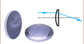
Principles of Spatial Filters
For many applications, such as holography, spatial intensity variations in the laser beam are unacceptable. Our KT311(/M) spatial filter system is ideal for producing clean Gaussian beams.
Figure 1: Spatial Filter System
The input Gaussian beam has spatially varying intensity "noise". When a beam is focused by an aspheric lens, the input beam is transformed into a central Gaussian spot (on the optical axis) and side fringes, which represent the unwanted "noise" (see Figure 2 below). The radial position of the side fringes is proportional to the spatial frequency of the "noise".
Figure 2
By centering a pinhole on a central Gaussian spot, the "clean" portion of the beam can pass while the "noise" fringes are blocked (see Figure 3 below).
Figure 3
The diffraction-limited spot size at the 99% contour is given by:

where λ = wavelength, ƒ=focal length and r = input beam radius at the 1/e2 point.
Choosing the Correct Optics and Pinhole for Your Spatial Filter System
The correct optics and pinhole for your application depend on the input wavelength, source beam diameter, and desired exit beam diameter.
For example, suppose that you are using a 650 nm diode laser source that has a diameter (1/e2) of 1.2 mm and want your beam exiting the spatial filter system to be about 4.4 mm in diameter. Based on these parameters, the C560TME-B mounted aspheric lens would be an appropriate choice for the input side of spatial filter system because it is designed for use at 650 nm, and its clear aperture measures 5.1 mm, which is large enough to accommodate the entire diameter of the laser source.
The equation for diffraction limited spot size at the 99% contour is given above, and for this example, λ = (650 x 10-9 m), f = 13.86 mm for the C560TM-B, and r = 0.6 mm. Substitution yields
Diffraction-Limited Spot Size (650 nm source, Ø1.2 mm beam)
The pinhole should be chosen so that it is approximately 30% larger than D. If the pinhole is too small, the beam will be clipped, but if it is too large, more than the TEM00 mode will get through the pinhole. Therefore, for this example, the pinhole should ideally be 19.5 microns. Hence, we would recommend the mounted pinhole P20K, which has a pinhole size of 20 μm. Parameters that can be changed to alter the beam waist diameter, and thus the pinhole size required, include changing the input beam diameter and focal length of focusing lens. Decreasing the input beam diameter will increase the beam waist diameter. Using a longer focal length focusing lens will also increase the beam waist diameter.
Finally, we need to choose the optic on the output side of the spatial filter so that the collimated beam's diameter is the desired 4.4 mm. To determine the correct focal length for the lens, consider the following diagram in Figure 4, which is not drawn to scale. From the triangle on the left-hand side, the angle is determined to be approximately 2.48o. Using this same angle for the triangle on the right-hand side, the focal length for the plano-convex lens should be approximately 50 mm.
Figure 4: Beam Expansion Example
For this focal length, we recommend the LA1131-B plano-convex lens [with f = 50 mm at the design wavelength (λ = 633 nm), this is still a good approximation for f at the source wavelength (λ = 650 nm)].
Note: The beam expansion equals the focal length of the output side divided by the focal length of the input side.
For optimal performance, a large-diameter aspheric lens can be used in place of a plano-convex lens if the necessary focal length on the output side is 20 mm (see AL2520-A, AL2520-B, AL2520-C). These lenses are 25 mm in diameter and can be held in place using the supplied SM1RR Retaining Ring.
Click to Enlarge
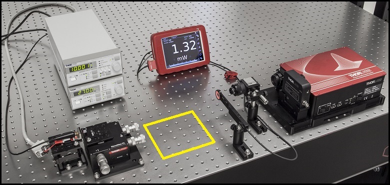
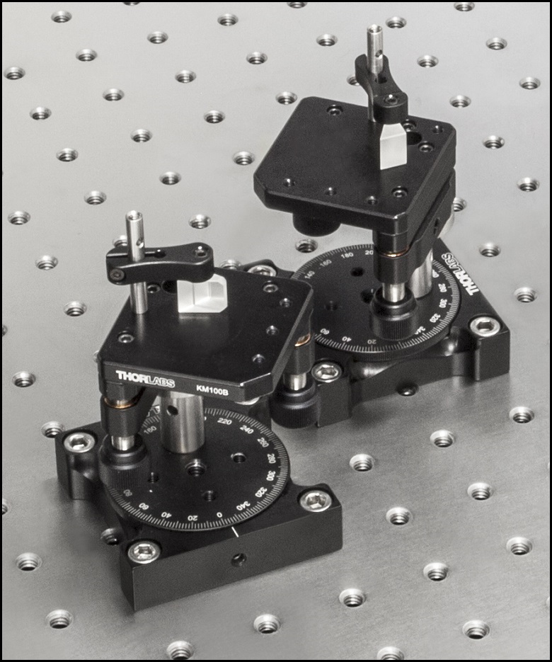
Figure 1: The beam circularization systems were placed in the area of the experimental setup highlighted by the yellow rectangle.


Click to Enlarge
Figure 4: Spatial Filter System
Click to Enlarge
Figure 3: Anamorphic Prism Pair System

Click to Enlarge
Figure 2: Cylindrical Lens Pair System
Comparison of Circularization Techniques for Elliptical Beams
Edge-emitting laser diodes emit elliptical beams as a consequence of the rectangular cross sections of their emission apertures. The component of the beam corresponding to the narrower dimension of the aperture has a greater divergence angle than the orthogonal beam component. As one component diverges more rapidly than the other, the beam shape is elliptical rather than circular.
Elliptical beam shapes can be undesirable, as the spot size of the focused beam is larger than if the beam were circular, and as larger spot sizes have lower irradiances (power per area). Techniques for circularizing an elliptical beam include those based on a pair of cylindrical lenses, an anamorphic prism pair, or a spatial filter. This work investigated all three approaches. The characteristics of the circularized beams were evaluated by performing M2 measurements, wavefront measurements, and measuring the transmitted power.
While it was demonstrated that each circularization technique improves the circularity of the elliptical input beam, each technique was shown to provide a different balance of circularization, beam quality, and transmitted power. The results of this work, which are documented in this Lab Fact, indicate that an application's specific requirements will determine which is the best circularization technique to choose.
Experimental Design and Setup
The experimental setup is shown in Figure 1. The elliptically-shaped, collimated beam of a temperature-stabilized 670 nm laser diode was input to each of our circularization systems shown in Figures 2 through 4. Collimation results in a low-divergence beam, but it does not affect the beam shape. Each system was based on one of the following:
- LJ1874L2-A and LJ1638L1-A Plano-Convex Convex Cylindrical Lenses (Figure 2)
- PS873-A Unmounted Anamorphic Prism Pair (Figure 3)
- Previous Generation KT310 Spatial Filter System with P5S Ø5 µm Pinhole (Figure 4)
The beam circularization systems, shown to the right, were placed, one at a time, in the vacant spot in the setup highlighted by the yellow rectangle. With this arrangement, it was possible to use the same experimental conditions when evaluating each circularization technique, which allowed the performance of each to be directly compared with the others. This experimental constraint required the use of fixturing that was not optimally compact, as well as the use of an unmounted anamorphic prism pair, instead of a more convenient mounted and pre-aligned anamorphic prism pair.
The characteristics of the beams output by the different circularization systems were evaluated by making measurements using a power meter, a wavefront sensor, and an M2 system. In the image of the experimental setup, all of these systems are shown on the right side of the table for illustrative purposes; they were used one at a time. The power meter was used to determine how much the beam circularization system attenuated the intensity of the input laser beam. The wavefront sensor provided a way to measure the aberrations of the output beam. The M2 system measurement describes the resemblance of the output beam to a Gaussian beam. Ideally, the circularization systems would not attenuate or aberrate the laser beam, and they would output a perfectly Gaussian beam.
Edge-emitting laser diodes also emit astigmatic beams, and it can be desirable to force the displaced focal points of the orthogonal beam components to overlap. Of the three circularization techniques investigated in this work, only the cylindrical lens pair can also compensate for astigmatism. The displacement between the focal spots of the orthogonal beam components were measured for each circularization technique. In the case of the cylindrical lens pair, their configuration was tuned to minimize the astigmatism in the laser beam. The astigmatism was reported as a normalized quantity.
Experimental Results
The experimental results are summarized in the following table, in which the green cells identify the best result in each category. Each circularization approach has its benefits. The best circularization technique for an application is determined by the system’s requirements for beam quality, transmitted optical power, and setup constraints.
Spatial filtering significantly improved the circularity and quality of the beam, but the beam had low transmitted power. The cylindrical lens pair provided a well-circularized beam and balanced circularization and beam quality with transmitted power. In addition, the cylindrical lens pair compensated for much of the beam's astigmatism. The circularity of the beam provided by the anamorphic prism pair compared well to that of the cylindrical lens pair. The beam output from the prisms had better M2 values and less wavefront error than the cylindrical lenses, but the transmitted power was lower.
| Method | Beam Intensity Profile | Circularitya | M2 Values | RMS Wavefront | Transmitted Power | Normalized Astigmatismb |
|---|---|---|---|---|---|---|
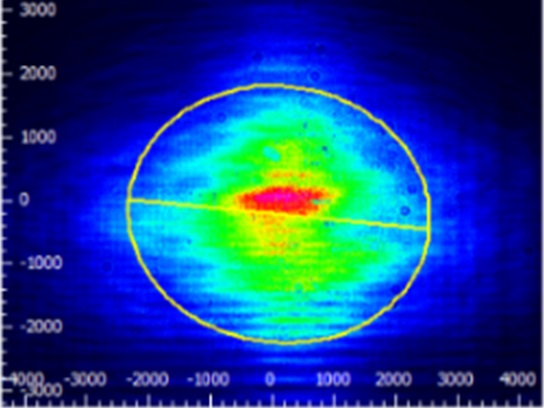
| Collimated Source Output (No Circularization Technique) |
 Click to Enlarge Scale in Microns |
0.36 | Y Axis: 1.63 |
0.17 | Not Applicable | 0.67 |
| Cylindrical Lens Pair |  Click to Enlarge Scale in Microns |
0.84 | X Axis: 1.90 Y Axis: 1.93 |
0.30 | 91% | 0.06 |
| Anamorphic Prism Pair |
 Click to Enlarge Scale in Microns |
0.82 | X Axis: 1.60 Y Axis: 1.46 |
0.16 | 80% | 1.25 |
| Spatial Filter | 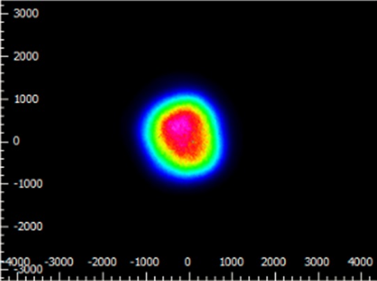 Click to Enlarge Scale in Microns |
0.93 | X Axis: 1.05 Y Axis: 1.10 |
0.10 | 34% | 0.36 |
Components used in each circularization system were chosen to allow the same experimental setup be used for all experiments. This had the desired effect of allowing the results of all circularization techniques to be directly compared; however, optimizing the setup for a circularization technique could have improved its performance. The mounts used for the collimating lens and the anamorphic prism pair enabled easy manipulation and integration into this experimental system. It is possible that using smaller mounts would improve results by allowing the members of each pair to be more precisely positioned with respect to one another. In addition, using made-to-order cylindrical lenses with customized focal lengths may have improved the results of the cylindrical lens pair circularization system. All results may have been affected by the use of the beam profiler software algorithm to determine the beam radii used in the circularity calculation.
Additional Information
Some information describing selection and configuration procedures for several components used in this experimental work can be accessed by clicking the following hyperlinks:
| Posted Comments: | |
prathmesh ghag
(posted 2022-05-05 14:56:32.35) Dear Sir/Maam,
i am have already purchased the following
pinhole model #P5HK
lens model #: N414TM-A.
Kindly confirm for me both are compatible with spatial filter system KT311/M.
If any adapter plates are required for mounting them with KT311/m, kindly let me know their model #.
Thanking you,
Prathmesh Ghag jdelia
(posted 2022-05-11 04:27:21.0) Thank you for contacting Thorlabs. These parts would not be compatible with the spatial filter as it comes. I have contacted you directly to discuss potential adapters and alternate optics for your application. |