 Products Home / Optomechanical Components / Irises / Apertures / Iris Diaphragms / Motorized Iris with Resonant Piezoelectric Motors
Motorized Iris with Resonant Piezoelectric Motors

- Motorized Iris for Precise Aperture Control
- Open Frame Design for OEM Applications
- Control via Interface Board, GUI, or ASCII Message Calls
- Post and Cage-System Mounting Options
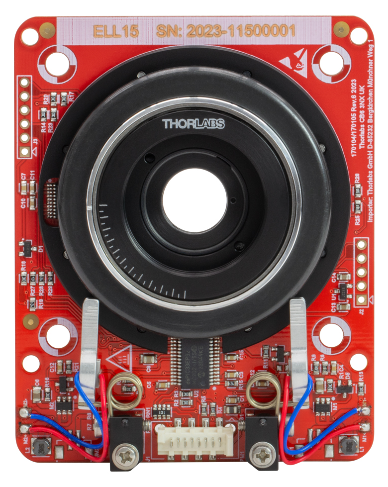
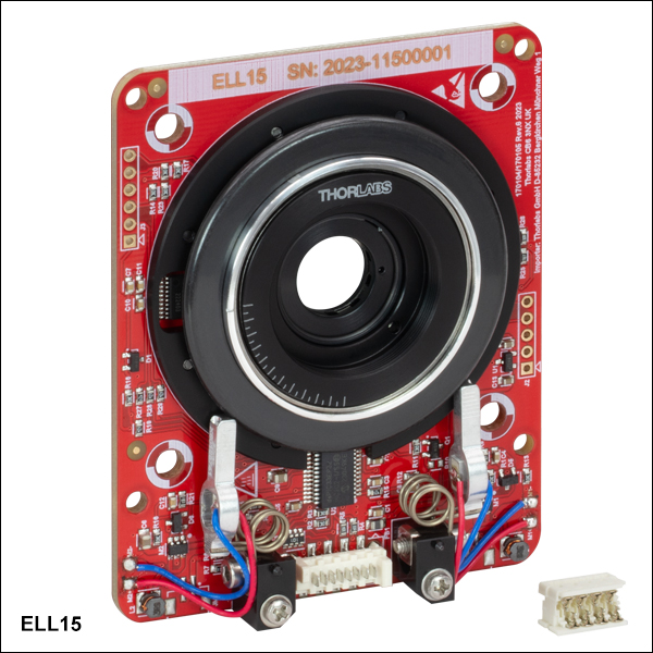
ELL15
Motorized Iris
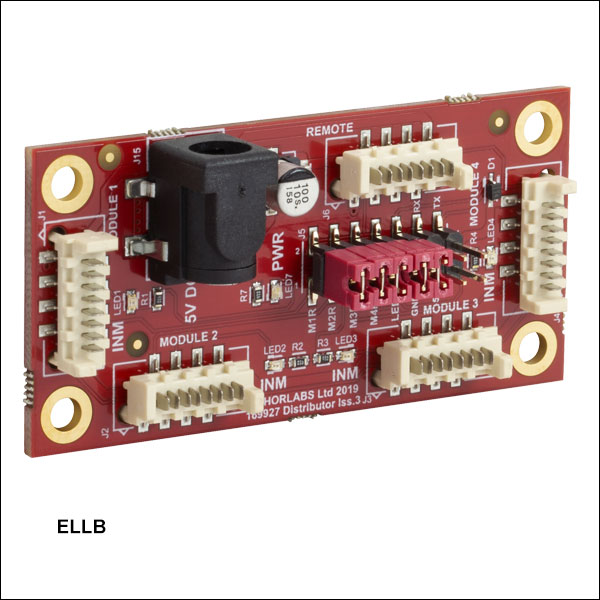
ELLB
Bus Distributor
Interface Board
(Included in ELL15K Bundle or Available with ELLC2 Accessory Kit)
Post-mounted ELL15 motorized iris in a 30 mm cage system with iris partially closed.


Please Wait
| Key Specificationsa | ||
|---|---|---|
| Iris Aperture Range | Ø1.0 mm - Ø11.5 mm | |
| Homing Repeatability | ±0.10 mm | |
| Unidirectional Repeatability | ±0.10 mm | |
| Maximum Closing Speedb | 500 ms | |
| Minimum Incremental Motion | 0.01 mm | |
| Rated Voltage | 4.5 to 5.5 V | |
| Weight of Iris | 100 g | |
| Minimum Lifetime | 1 million Iris Movements | |
| Iris Dimensions |
66.0 mm x 82.5 mm x 19.1 mm (2.6" x 3.25" x 0.75") |
|

Click to Enlarge
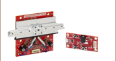
The components of the ELL15K Motorized Iris Bundle are shown connected and with key features labeled.
 Thorlabs' Elliptec Technology for OEM
Click to Enlarge
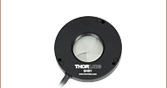
The ELL15 can be post-mounted using a CP33B bracket for use in optical setups.
Features
- Ideal for OEMs and Applications Requiring Rapid and Precise Iris Adjustments
- Micro-B USB and Picoflex®1 Connectors for Control Signals
- Multi-Drop Serial Communication Protocol Supported
- Compatible with 30 or 60 mm Cage Systems and SM1-Threaded Components
- Can be Post Mounted Using the CP33B Bracket
- Magnetic Encoder used to Position Iris to Desired Aperture with Repeatability of ±0.10 mm
- Bus Distributor Facilitates Control of up to Four Elliptec® Devices
- ELLC2 Accessory Upgrade Pack Available Below
Driven by Thorlabs' Elliptec® piezoelectric resonant motor technology, this motorized iris is designed to be a compact solution for applications requiring precise and repeatable aperture sizing. The iris is offered as a standalone unit (Item # ELL15), or as part of a bundle (Item # ELL15K) that also contains an interface board for manual control of the iris, power supply, and cables for connecting the iris and interface board to each other and to a PC. Thorlabs also offers the ELLC2 Accessory Pack which can be used to upgrade standalone units to kits.
Each motorized iris is internally SM1 (1.035"-40) threaded. It is designed to be lightweight and compact, and the closed-loop operation provides movement to the specified aperture size with a repeatability of ±0.10 mm. The assembled components of the ELL15K are shown in the image to the far right, with key features labeled. Please see The Elliptec® Motor tab for more information.
The motors are highly dynamic and have no gearing. The tips of both motor housings are in firm contact with the plastic track at the base of iris, as can be seen in the image to the far right. The motorized iris is not designed for continuous operation. Operation with duty cycles of 40% or less is recommended. When power is not applied to the motors, the iris is held in place by an approximately 0.01 N·m combined torque exerted by the stationary arms of the motors.
The open frame format, versatility, and simplicity of this motorized iris make it attractive for OEM applications, as it can be customized according to customer requirements and produced in high-volume quantities. Please contact us to discuss your specific requirements so that we may tailor a solution to meet the needs of your application.
Control
There are multiple options for powering, driving, and controlling this motorized iris, which are detailed in the Positioning the Motorized Iris section of the Operation tab. The iris possesses a 3.3 V serial bus and is designed to be operated with or without the interface board; the Pin Diagram tab provides pin assignments. Thorlabs offers software for our Elliptec products capable of providing full and independent control of the iris. When the interface board is used as an accessory to change the position of the iris, its status in the software is automatically updated.
| Elliptec Resonant Motor Products | |||||
|---|---|---|---|---|---|
 |
 |
 |
 |
 |
 |
| Multi-Position Sliders | 28 mm Linear Stage | 60 mm Linear Stage | Rotation Stage | Rotation Mount | Motorized Iris |
Multiple Elliptec devices can be controlled using the ELLB Bus Distributor or by splicing multiple connectors onto one ribbon cable. A single bus distributor can connect up to four Elliptec devices; up to 16 devices can be connected if the buses are daisy chained. This bus can be controlled in one of three ways: through an interface board (included with the bundles below) to connect to a PC running the Elliptec software, by connecting to an Arduino®2 or Raspberry Pi®3 board, or by wiring the connector pins to a user-supplied control board. Alternatively, up to 16 devices can be spliced onto a single ribbon cable. The devices can then be simultaneously controlled by the interface board or selectively controlled by the Elliptec software. See the manual for instructions on how to splice multiple devices onto a ribbon cable and the Pin Diagrams tab for pin assignments when making custom connections.
- Picoflex is a registered trademark of Molex Incorporated.
- Arduino is a registered trademark of Arduino Sa Société Anonym (SA).
- Raspberry Pi is a registered trademark of the Raspberry Pi Foundation.
| Specifications | |
|---|---|
| Iris Aperture Range | Ø1.0 - Ø11.5 mm |
| Minimum Lifetime | 1 million Iris Movements |
| Recommended Duty Cyclea | 40% |
| Max Closing Speedb | 500 ms |
| Unidirectional Repeatability | ±0.10 mm |
| Homing Repeatability | ±0.10 mm |
| Backlash | 0.20 mm |
| Encoder Resolution | 1,000 counts/mm |
| Minimum Incremental Motion | 0.01 mm |
| Minimum Motor Holding Torque (Both Motors Engaged) |
0.01 N•m |
| Limit Switches | Electronic and Mechanical |
| Mounting | 30 mm Cage System: 4-40 Tapped Holes (4 Places) 60 mm Cage System: 3.0 mm Thru Holes (4 Places) Fixed Internal SM1 Threads (2 Places) |
| Rated Voltage | 4.5 to 5.5 V |
| Typical Current Consumption During Movement | 800 mA |
| Standby Current | 50 mA |
| Motor Type | Elliptec® Resonant Piezo |
| 8-Conductor Ribbon Cable Length (Supplied) | 250 mm |
| 8-Conductor Ribbon Cable Length (Maximum) | 3 m |
| Operating Temperature Range | 15 - 40 °C (59 - 104 °F) |
| Dimensions | 66.0 x 82.5 x 19.1 mm (2.60" x 3.25" x 0.75") |
| Weight (ELL15 only) | 100 g |

Click to Enlarge
Components of the ELL15K Bundle
(One Region-Specific Power Adapter Included with the Power Supply)

Click to Enlarge
Simplified Mechanical Drawing of the Motorized Iris.
For more information on mounting options see the Operation tab.

Click to Enlarge
Mechanical Drawing of the Interface Board
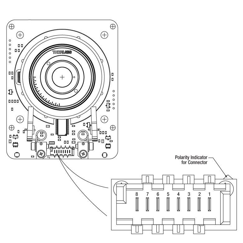
ELL15 Pinout for Connector J1
| ELL15 Connector J1 Pinouta | ||
|---|---|---|
| Pin | Type | Function |
| 1 | PWR | Ground |
| 2 | OUT | OTDX - Open Drain Transmit 3.3 V TTL RS232 |
| 3 | IN | RX Receive - 3.3 V TTL RS232 |
| 4 | OUT | In Motion, Open Drain Active Low Max 5 mA |
| 5 | IN | JOG/Mode, Active Low Max 5 V |
| 6 | IN | BW Backward, Active Low Max 5 V |
| 7 | IN | FW Forward, Active Low Max 5 V |
| 8 | PWR | VCC +5 V ±10%; 800 mA |
Click to Enlarge
Pinout diagram of the Picoflex® connector is shown referended to a partial diagram
of the ELL15 Motorized Iris.
ELLB Pinout for Connectors J1, J2, J3, and J4
| ELLB Connector J1, J2, J3, and J4 Pinouta,b | ||
|---|---|---|
| Pin | Type | Function |
| 1 | PWR | Ground |
| 2 | OUT | OTDX - Open Drain Transmit 3.3 V TTL RS232 |
| 3 | IN | RX Receive 3.3 V TTL RS232 |
| 4 | OUT | In Motion, Open Drain Active Low Max 5 mA |
| 5 | IN | Not Connected |
| 6 | IN | Not Connected |
| 7 | IN | Not Connected |
| 8 | PWR | VCC +5 V ± 10%; 800 mA per Connected Device |
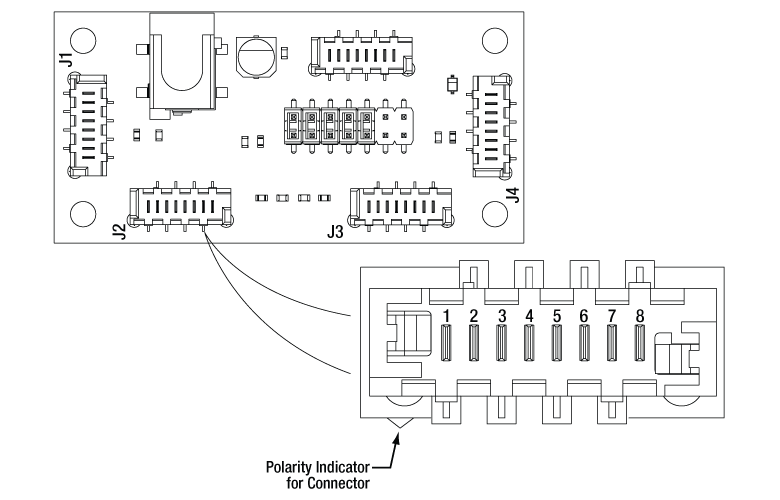
Click to Enlarge
Pinout diagram of the Picoflex® connector is shown referenced to a simplified diagram
of the ELLB Bus Distributor. The polarity indicator on the connector
must be adjacent to the red wire on the supplied 8-connector cables.
Operation Notes
This tab contains information on handling, mounting, and operating the ELL15K Motorized Iris Bundle.
Contents- Handling
- Mounting the Motorized Iris
- Supplying Power
- Operation of the Motors
- Homing the Motorized Iris
- Positioning the Motorized Iris
- Resonance Frequencies

Click to Enlarge
The Motorized Iris, Back
Click to Enlarge
The Motorized Iris, Front
Handling
The motorized iris and interface board included in the ELL15K bundle are robust to general handling. To ensure reliable operation, keep the surface of the plastic track contacted by the motors free of oils, dirt, and dust. It is not necessary to wear gloves while handling the motorized iris, but avoid touching the track to keep it free of oils from fingerprints. If it is necessary to clean the track, it may be wiped with isopropyl alcohol or mineral spirits (white spirit). Do not use acetone, as this solvent will damage the plastic track.
The open frame format of the ELL15 can tolerate up to 8 kV of static discharge. ESD precautions should be taken, as an electrostatic discharge can produce an electrical signal that may cause an unintended movement of the iris. A bending load in excess of 500 g applied to the board may cause the PCB to deform, which will degrade the performance of the motorized iris. As readings from a magnetic sensor are used during the homing and positioning of the iris, avoid subjecting the structural PCB to excessive loads or magnetic fields. Limit the strength of magnetic fields in proximity to the magnetic sensor to ±5 mT to avoid negatively affecting the homing and positioning operations.
Mounting the Motorized Iris
The motorized iris may be mounted either vertically or horizontally. The Elliptec motors should be facing up if the iris is used horizontally. The iris has several mounting features that can be used with Thorlabs components or within a custom OEM assembly. Four Ø0.12" (3.0 mm) through holes are spaced 60 mm apart and provide compatibility with our 60 mm cage system. These holes can pass 4-40 or M3 screws for mounting to custom structures. Additionally, there are four Ø4.2 mm (Ø0.17") through holes spaced 50 mm apart which can be used with 6-32 or M4 screws for custom mounting. The back of the iris features four 4-40 tapped holes 30 mm apart for terminating integration into our 30 mm cage systems. A cage system adapter could be used if termination is not desired. These holes can also be used with a CP33B cage mounting bracket for post mounting.
The motorized iris also features internal SM1 (1.035"-40) threading on both sides of the iris, allowing for integration into systems utilizing Ø1" lens tubes.

Click for Details
The motorized iris can be mounted in a 60 mm cage system by sandwiching the PCB between two cage rods using the Ø0.12" (3.0 mm) holes in the corners.

Click for Details
The motorized iris can be mounted in a 30 mm cage system using ER-Series cage rods in the Ø0.16" (4.0 mm) holes on the back of the mount.

Click to Enlarge
The motorized iris can be post-mounted and has threading for SM1 lens tubes for applications requiring light exclusion.

Click to Enlarge
Features of the Motorized Iris
Supplying Power
When the setup includes the interface board, power is supplied through the 5 VDC power socket located on the board. The electronics on the interface board convert the applied DC signal to a sinusoidal signal oscillating at the required resonance frequency.
The ELL15K bundle includes a 5 VDC power supply whose connector mates with the power socket on the interface board. Delivering power through this socket also allows the Micro-B USB connector to be used for a computer to control the iris remotely. The power supplied by a computer through the USB 2.0 connection is not sufficient to power the iris.
When the implementation does not include the interface board, the connection with the power source is made using the pins on the Picoflex® connector that is included on the motorized iris board. A pinout diagram of this connector is included in the Pin Diagram tab, and information on powering and addressing the motorized iris is given in the manual and the communications protocol manual, respectively.
Operation of the Motors
The motion of the motorized iris is controlled by forcing the piezoelectric elements to vibrate at specific ultrasonic frequencies. For each motor, there is one ultrasonic resonant frequency that will push the iris forward (open), and another that will pull the mount backward (close). Operating a motor at one of its resonance frequencies causes the tip of the motor to continuously cycle in a tight clockwise elliptical path. When the motor is driven at its other resonant frequency, the tip of the motor cycles through that same path in a counterclockwise direction. Both resonant frequencies are around 100 kHz. The total displacement at the tip of motor is a function of the mechanical load it is driving and the voltage supplied to the piezo element. In the case of no loading and a 5 V maximum driving voltage at a resonant frequency, the tip of the motor expands and contracts no more than a few microns while tracing the elliptical path. Please see The Elliptec® Motor tab for more information and an animation illustrating the operational principle of the motors.
Homing the Motorized Iris
Click to Enlarge
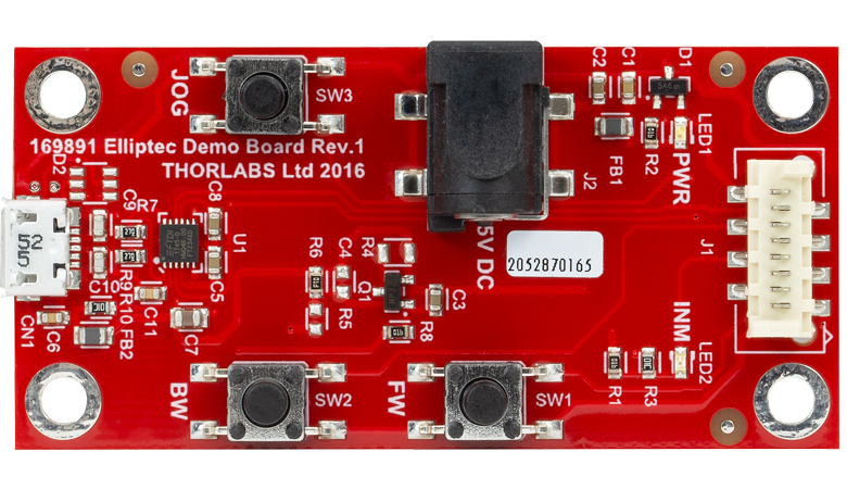
The Interface Board
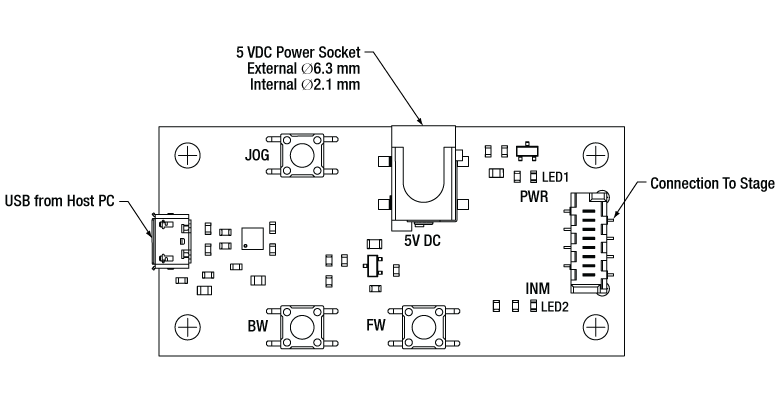
Click to Enlarge
Features of the Interface Board
Homing is achieved using a combination of a reflecting optical sensor (infrared) for coarse positioning, followed by a magnetic sensor for fine positioning.
To Home the iris, press the BW button on the interface board, click the Home button in the Elliptec software's graphical user interface (GUI) or send the appropriate ASCII message as is specified in the communications protocol manual.
The default Home position is set to be the maximum aperture (Ø11.5 mm). If desired, the user may redefine the position of Home to be offset from the default position down to the minimum aperture of Ø1.0 mm. By default, the device is set to auto-home at startup. This function can be deactivated using the command indicated in the communications protocol manual. If the auto-homing function is deactivated, the user must Home the iris prior to performing any JOG moves.
Positioning the Motorized Iris
Note that the motorized iris is not intended for continuous operation. We recommend operation with duty cycles of less than 40% during general use, while operation with duty cycles greater than 60% should be limited to a few seconds.
The iris is auto-homed at startup unless the user deactivates this function. Please see the previous section for details. The movement of the iris may be controlled through a computer running the Elliptec® software package or by sending simple signals to digital lines on the iris's board. A link to download the software and accompanying documentation can be found in the Software tab.
The default increment to open and close the aperture is 0.5 mm, and a custom increment can be set using the Elliptec software or by sending the appropriate ASCII message(s) as specified in the communications protocol manual. The Elliptec software can be used to set the iris to absolute and relative positions, in addition to jogging the iris open or close. The software is also used to set the jog step size, read the position of the iris, and adjust the position of Home, as is described in the previous section. The interface board has the ability to save one custom aperture setting for easy recall. Please see the manual for details.
Readings from the magnetic sensor are used to position the iris and when executing the Home command. The range of the iris is limited to apertures from Ø1.0 mm to Ø11.5 mm with a minimum incremental movement of 0.01 mm and a repeatability of ±0.1 mm.
Multiple Elliptec devices can be be controlled using the ELLB Bus Distributor or by splicing multiple connectors onto one ribbon cable. A single bus distributor can connect up to four Elliptec devices; up to 16 devices can be connected if the buses are daisy chained. This bus can be controlled one of three ways: through an interface board (included with the bundles below) to connect to a PC running the Elliptec software, by connecting to an Arduino® or Raspberry Pi® board, or by wiring the connector pins to a user-supplied control board. Note that if an interface board is used, its on-unit buttons will be disabled. Alternatively, up to 16 devices can be spliced onto a single ribbon cord. The devices can then be simultaneously controlled by the interface board or selectively controlled by the Elliptec software. See the manual for instruction on how to splice multiple devices onto a ribbon cord and the Pin Diagrams tab for pin assignments when making custom connections. The communications protocol manual describes how to use the software to individually address each connected device. A link to download the software and accompanying documentation can be found in the Software tab.
Resonance Frequencies
Due to load, build tolerances and other mechanical variances, the default resonating frequency of a particular motor may not be that which delivers best performance. A frequency search can be performed using the Main GUI Settings panel in the Elliptec software, or by using the serial communication line (SEARCHFREQ_MOTORX message), which offers a way to optimize the operating frequencies for backward (close) and forward (open) movement. A new search for optimal resonance frequencies may be performed at any time. To maintain optimal performance, it is recommended that new searches be performed after changes in loading and/or ambient temperature. Please see the manual for details.
Click to Enlarge
The Components of the Elliptec Motor
Click to Enlarge
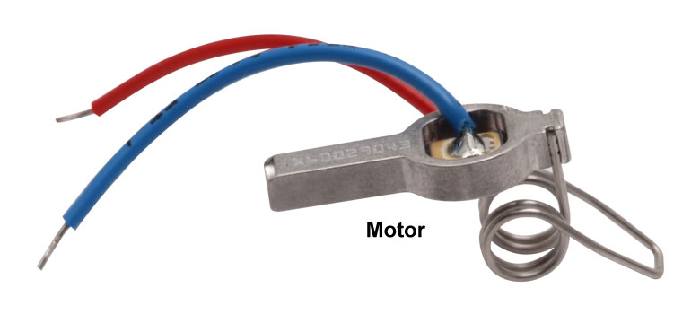
The Elliptec Piezoelectric Resonant Motor
The Elliptec® Piezoelectric Resonant Motor
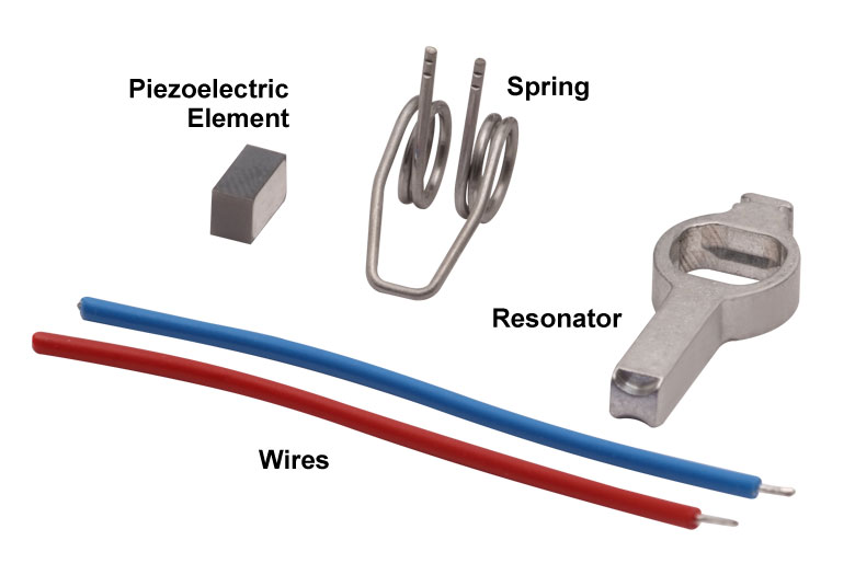
Thorlabs' Elliptec® piezo resonant motor, shown at right, is lightweight, with a mass of 1.2 g, and compact: the dimensions of the resonator housing, excluding the spring, are 8 mm x 4 mm x 20 mm.
Components of the Motor
The components that compose the motor are shown at far-right. The piezoelectric element is press fit into the aluminum resonator, which has been precisely designed and machined to produce the desired elliptical motion at the tip and to interface optimally with the driven module. The free ends of the spring are integrated with the resonator housing. The wires, which are soldered to the top and bottom of the piezoelectric element, deliver the voltage signal that induces the piezoelectric element to vibrate at ultrasonic frequencies.
When the motor is built into a system, the open loop of the spring is bolted to a sturdy surface that is stationary with respect to the item to be driven, and the tip of the resonator is placed in contact with the item. The purpose of the spring is to maintain constant contact between the tip of the resonator and the driven item, and the direction of motion is determined by the resonance frequency at which the piezo element is driven.
Elliptical Motion and Comparison with Conventional Motors
The motor is operated by driving it at one of its two resonance frequencies. A voltage signal oscillating at an ultrasonic frequency is applied to the piezoelectric chip, which responds by expanding less than a micron and then contracting back to its original dimensions at the frequency of the driving signal. This rapid-cycling change in the chip's dimensions causes a vibration in the aluminum resonator housing. When the vibration is at one of the housing's resonance frequencies, a pushing motion results at the tip of the motor. When the vibration is at the other resonance frequency a pulling motion results.
As illustrated in the video, the pulling and pushing motions result from the tip of the motor tracing an elliptical path in space when the motor operates at resonance. The selected resonance frequency controls the direction of the cyclical motion. The motor's tip traces one half of the ellipse as it expands and the other half as it contracts. When the motor pushes the driven item, the motor's tip is in contact with the item while the tip expands; the two are not in contact while the tip contracts. The converse is true when the motor pulls the driven item in the opposite direction. The total displacement at the tip of the motor is a function of both the mechanical load it is driving and the voltage supplied to the piezo element. The maximum displacement can be up to a few microns when the peak driving voltage is 5 V.
The motor behaves in many ways like a DC or electromagnetic stepper motor, but it does not suffer from many of the drawbacks of these conventional motors. Unlike conventional electromagnetic motors, which must overcome inertial delays to come to a stop, the highly dynamic Elliptec motor can stop within microseconds. As it has no gears, it does not exhibit backlash. Since it possesses no magnets, it is compatible with use in environments sensitive to electromagnetic interference. The motion of the driven element is continuous and smooth. As the tip of the motor must be in contact with the driven item to induce motion, the motor possesses the safety feature of an inherent friction brake. When in contact with a plastic surface, the motor operates virtually silently.
For OEM applications, the motor can be manufactured in volume at low cost, and it can be driven by inexpensive analog electronics. It does not require microprocessors or software; however it is compatible for use with them.

Click to Enlarge
The Elliptec Piezoelectric Resonant Motor Control Software GUI for the ELL15.
Software for Devices Driven by Elliptec® Piezoelectric Resonant Motors
All devices based on the Elliptec® resonant piezo motor may be controlled by the Elliptec system software, which features an intuitive graphical user interface (GUI). The source code, in C# format, is included in software bundle available for download, and custom applications can be created in any language. The image at right shows a screen capture of the GUI, and the button that follows links to the download page.
Commands are entered in the Sequencer command / wait order section located at the center-left of the GUI. An example of a sequence of commands that might be sent to the device is "Aho0" to move to the rotation stage at address "A" to the home position in the clockwise direction, and then "Afw" to move the stage at address "A" forward by the jog increment. The command "As1" is used to perform the frequency search that will identify the optimal resonant frequencies, for the current operating conditions, for Motor 1 at adddress "A."
Software
Version 1.6.3
Includes the Elliptec System Software, with an easy-to-use GUI. Also available for download is the Communications Protocol manual, which details the communication commands for the Elliptec software package.

Insights into Aligning a Laser Beam
When installing a laser in an optical setup, it is good practice to start by leveling and orienting its beam so that it travels along a well-defined path. When the beam is prepared this way, not only is it easier to then divert the beam and route it through the optical elements in the system, but the results provided by tuning the system's alignment are more predictable and repeatable. The following sections describe how to:
- Level and Align the Laser Beam's Pointing Angle
- Divert the Beam and Align it to Follow a Desired Path
Click here for more Insights about lab practices and equipment.
Level and Align the Laser Beam's Pointing Angle
0:00 - Introduction
1:25 - Level and Align the Laser Beam's Pointing Angle
4:09 - Divert the Beam and Align it to Follow a Desired Path

Click to Enlarge
Figure 2: The beam can be aligned to travel parallel to a line of tapped holes in the optical table. The yaw adjustment on the kinematic mount adjusts the beam angle, so that the beam remains incident on the ruler's vertical reference line as the ruler slides along the line of tapped holes.
Click to Enlarge
Figure 1: Leveling the beam path with respect to the surface of an optical table requires using the pitch adjustment on the kinematic laser mount (Figure 2). The beam is parallel to the table's surface when measurements of the beam height near to (left) and far from (right) the laser's front face are equal.
Pitch (tip) and yaw (tilt) adjustments provided by a kinematic mount can be used to make fine corrections to a laser beam's angular orientation or pointing angle. This angular tuning capability is convenient when aligning a collimated laser beam to be level with respect to a reference plane, such as the surface of an optical table, and when aligning with respect to a particular direction in that plane, such as along a line of tapped holes in the table.
Before Using the Mount's Adjusters
First, rotate each adjuster on the kinematic mount to the middle of its travel range. This reduces the risk of running out of adjustment range, and the positioning stability is frequently better when at the center of an adjuster's travel range.
Then, make coarse corrections to the laser's height, position, and orientation. This can be done by adjusting the optomechanical components, such as a post and post holder, supporting the laser. Ensure all locking screws are tightened after the adjustments are complete.
Level the Beam Parallel to the Table's Surface
Leveling the laser beam is an iterative process that requires an alignment tool and the fine control provided by the mount's pitch adjuster.
Begin each iteration by measuring the height of the beam close to and far from the laser (Figure 1). A larger distance between the two measurements increases accuracy. If the beam height at the two locations differs, place the ruler in the more distant position. Adjust the pitch on the kinematic mount until the beam height at that location matches the height measured close to the laser. Iterate until the beam height at both positions is the same.
More than one iteration is necessary, because adjusting the pitch of the laser mount adjusts the height of the laser emitter. In the video for example, the beam height close to the laser was initially 82 mm, but it increased to 83 mm after the pitch was adjusted during the first iteration.
If the leveled beam is at an inconvenient height, the optomechanical components supporting the laser can be adjusted to change its height. Alternatively, two steering mirrors can be placed after the laser and aligned using a different procedure, which is detailed in the section. Steering mirrors are particularly useful for adjusting beam height and orientation of a fixed laser.
Orient the Beam Along a Row of Tapped Holes
Aligning the beam parallel to a row of tapped holes in the table is another iterative process, which requires an alignment tool and tuning of the mount's yaw adjuster.
The alignment tool is needed to translate the reference line provided by the tapped holes into the plane of the laser beam. The ruler can serve as this tool, when an edge on the ruler's base is aligned with the edges of the tapped holes that define the line (Figure 2).
The relative position of the beam with respect to the reference line on the table can be evaluated by judging the distance between the laser spot and vertical reference feature on the ruler. Vertical features on this ruler include its edges, as well as the columns formed by different-length rulings. If these features are not sufficient and rulings are required, a horizontally oriented ruler can be attached using a BHMA1 mounting bracket.
In the video, when the ruler was aligned to the tapped holes and positioned close to the laser, the beam's edge and the ends of the 1 mm rulings coincided. When the ruler was moved to a farther point on the reference line, the beam's position on the ruler was horizontally shifted. With the ruler at that distant position, the yaw adjustment on the mount was tuned until the beam's edge again coincided with the 1 mm rulings. The ruler was then moved closer to the laser to observe the effect of adjusting the mount on the beam's position. This was iterated as necessary.
Divert the Beam and Align it to Follow a Desired Path
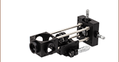
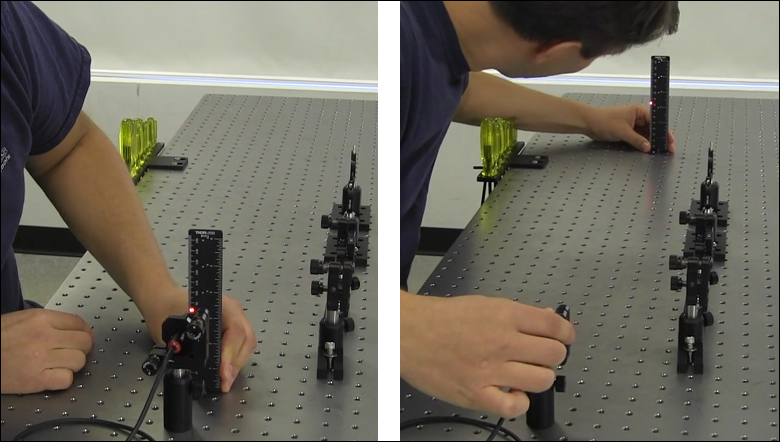
The first steering mirror reflects the beam along a line that crosses the new beam path. A second steering mirror is needed to level the beam and align it along the new path. The procedure of aligning a laser beam with two steering mirrors is sometimes described as walking the beam, and the result can be referred to as a folded beam path. In the example shown in the video above, two irises are used to align the beam to the new path, which is parallel to the surface of the optical table and follows a row of tapped holes.
Click to Enlarge
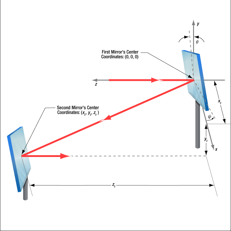
Figure 3: The beam reflected from Mirror 1 will be incident on Mirror 2, if Mirror 1 is rotated around the x- and y-axes by angles θ and ψ, respectively. Both angles affect each coordinate (x2 , y2 , z2 ) of Mirror 2's center. Mirror 1's rotation around the x-axis is limited by the travel range of the mount's pitch (tip) adjuster, which limits Mirror 2's position and height options.
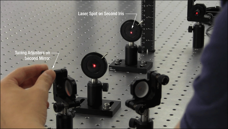
Click to Enlarge
Figure 5: The adjusters on the second kinematic mirror are used to align the beam on the second iris.

Click to Enlarge
Figure 4: The adjusters on the first kinematic mirror mount are tuned to position the laser spot on the aperture of the first iris.
Setting the Heights of the Mirrors
The center of the first mirror should match the height of the input beam path, since the first mirror diverts the beam from this path and relays it to a point on the second mirror. The center of the second mirror should be set at the height of the new beam path.
Iris Setup
The new beam path is defined by the irises, which in the video have matching heights to ensure the path is level with respect to the surface of the table. A ruler or calipers can be used to set the height of the irises in their mounts with modest precision.
When an iris is closed, its aperture may not be perfectly centered. Because of this, switching the side of the iris that faces the beam can cause the position of the aperture to shift. It is good practice to choose one side of the iris to face the beam and then maintain that orientation during setup and use.
Component Placement and Coarse Alignment
Start by rotating the adjusters on both mirrors to the middle of their travel ranges. Place the first mirror in the input beam path, and determine a position for the second mirror in the new beam path (Figure 3). The options are notably restricted by the travel range of the first mirror mount's pitch (tip) actuator, since it limits the mirror's rotation (θ ) around its x-axis. In addition to the pitch, the yaw (tilt) of the first mirror must also be considered when choosing a position
After placing the second mirror on the new beam path, position both irises after the second mirror on the desired beam path. Locate the first iris near the second mirror and the second iris as far away as possible.
While maintaining the two mirrors' heights and without touching the yaw adjusters, rotate the first mirror to direct the beam towards the second mirror. Adjust the pitch adjuster on the first mirror to place the laser spot near the center of the second mirror. Then, rotate the second mirror to direct the beam roughly along the new beam path.
First Hit a Point on the Path, then Orient
The first mirror is used to steer the beam to the point on the second mirror that is in line with the new beam path. To do this, tune the first mirror's adjusters while watching the position of the laser spot on the first iris (Figure 4). The first step is complete when the laser spot is centered on the iris' aperture.
The second mirror is used to steer the beam into alignment with the new beam path. Tune the adjusters on the second mirror to move the laser spot over the second iris' aperture (Figure 5). The pitch adjuster levels the beam, and the yaw adjuster shifts it laterally. If the laser spot disappears from the second iris, it is because the laser spot on the second mirror has moved away from the new beam path.
Tune the first mirror's adjusters to reposition the beam on the second mirror so that the laser spot is centered on the first iris' aperture. Resume tuning the adjusters on the second mirror to direct the laser spot over the aperture on the second iris. Iterate until the laser beam passes directly through the center of both irises, as shown in the video. If any adjuster reaches, or approaches, a limit of its travel range, one or both mirrors should be repositioned and the alignment process repeated.
If a yaw axis adjuster has approached a limit, note the required direction of the reflected beam and then rotate the yaw adjuster to the center of its travel range. Turn the mirror in its mount until the direction of the reflected beam is approximately correct. If the mirror cannot be rotated, reposition one or both mirrors to direct the beam roughly along the desired path. Repeat the alignment procedure to finely tune the beam's orientation.
If a pitch axis adjuster has approached a limit, either increase the two mirrors' separation or reduce the height difference between the new and incident beam paths. Both options will result in the pitch adjuster being positioned closer to the center of its travel range after the alignment procedure is repeated.
| Posted Comments: | |
Daniel Du
(posted 2023-10-21 13:34:25.46) Hello! Would it be possible to receive a set of two ELL15K packs with the capability for the iris to achieve a minimum diameter of 0.5mm or even smaller? Many thanks! Daniel Du do'neill
(posted 2023-10-26 06:13:33.0) Response from Daniel at Thorlabs. Currently we can not offer this due to the physical limitations of the motors. However I have passed on your request to our engineering team to evaluate for the future. I will reach out to you directly to discuss your application. |

 Zoom
Zoom
Click to Enlarge
The motors' aluminum tips contact the black plastic track encircling the motorized iris. This track should not be touched to prevent debris and oil building up on the track.
- Ideal for OEM Evaluation Testing
- Easily Integrate into a Setup
- Operate using Manual and/or Computer Control
- Included Power Supply is Required for Powering the Iris
Thorlabs' Motorized Iris Bundle is a complete package that includes the ELL15 motorized iris. The ELL15K package facilitates quick integration of the motorized iris into laboratory setups and other experimental applications. It also provides a convenient means to evaluate incorporating this technology into OEM applications.
The tips of both motor housings are in firm contact with the plastic track encircling the motorized iris, as can be seen in the image to the right. The motors are installed with opposite orientations and clockwise (and counterclockwise) rotation occurs when one motor pushes the track forward while the other pulls it backward.
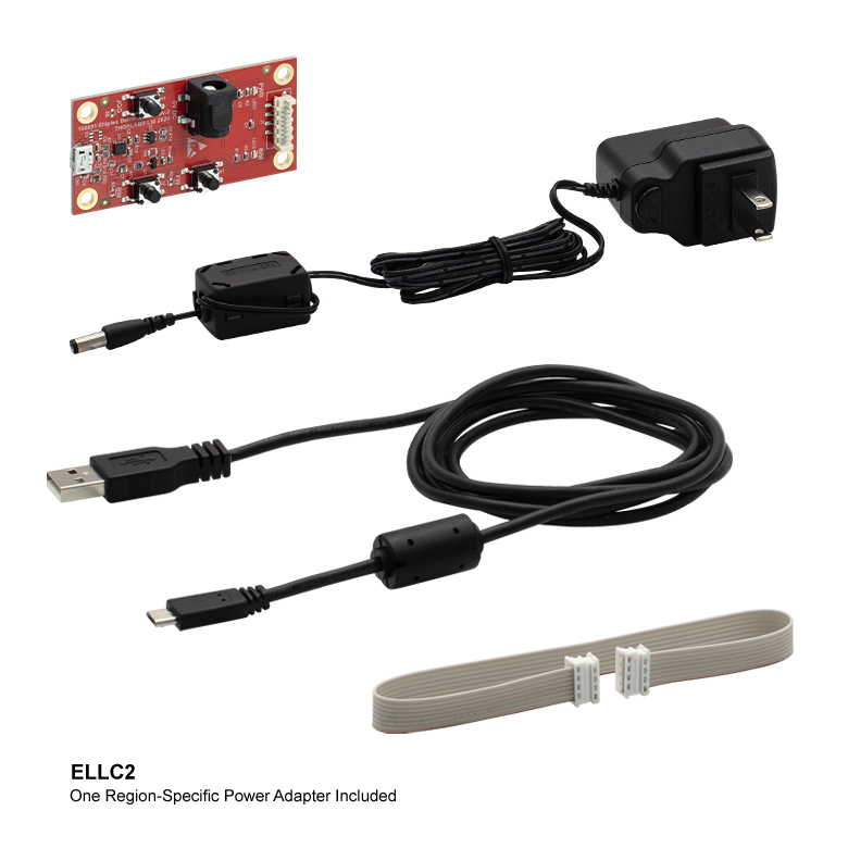
| Included in the ELL15K Bundle | |
|---|---|
| ELL15 Motorized Iris | 5 V Power Supply with Region-Specific Power Adapter |
| Interface Board | 8-Conductor 28 AWG Ribbon Cable |
| USB Cable | PC-Based Software for Download |

 Zoom
ZoomClick to Enlarge
Features of the Motorized Iris
Thorlabs' ELL15 Motorized Iris is offered to meet the needs of applications whose designs require multiple networked Elliptec® resonant motor products. The inner ring is fixed and has two SM1 threads for attaching a lens tube on both sides, enabling a light-tight setup. Details describing the dimensions, including the spacing of mounting holes, and other specifications of the iris are given in the Specs tab. Please contact us to discuss customizing the motorized iris.
The PCB of the motorized iris incorporates a male 8-pin Picoflex® connector (header). Each ELL15 iris ships with the female 8-pin Picoflex® connector (receptacle) that mates with the connector (header) on the board.

 Zoom
Zoom| Specifications | ||
|---|---|---|
| Item # | ELLC2 | |
| DC Voltage Input to Controller | 4.5 to 5.5 V | |
| Typical Current Consumption Per Module | Movement | 800 mA |
| Standby | 50 mA | |
| Operating Temperature Range | 15 to 40 °C | |
| Ribbon Cable Length (1 Included) | 250 mm (9.84") | |
| Maximum Supported Ribbon Cable Length |
500 mm (19.68") | |
| Dimensions (Interface Only) | 66.0 mm x 32.0 mm x 12.5 mm (2.60" x 1.26" x 0.49") |
|
| Weight (Interface Only) | 10.8 g (0.022 lbs) | |
- Convert Any Single ELL Device into a Kit by Adding the Following:
- Handheld Controller
- USB Micro B Cable
- Picoflex®1 Cable
- 5 V Power Supply with Regional Adapter (US, UK, AU, or EU)

Click for Details
Region-Specific Adapters for the ELLC2 Power Adapter
Thorlabs' ELLC2 Accessory Upgrade Pack is designed to include all of the items necessary to convert any single ELL slider, stage, or mount into an ELL kit2. The included handheld controller features three buttons to control the position of a connected ELL stage and the USB port enables direct connection to a PC via the included USB Micro B cable. A 0.25 m Picoflex® cable with 8 loaded circuits that connects the handheld controller to the ELL device and a 5 V power supply with a regional adapter (US, UK, AU, or EU) are also included with the kit.
- Note: Picoflex® is a registered trandemark of Molex Incorporated.
- Mounting brackets for the ELL17(/M), ELL18(/M), and ELL20(/M) can be ordered by contacting Tech Support.

 Zoom
Zoom| Specifications | ||
|---|---|---|
| Item # | ELLB | |
| Voltage Rating | 4.5 to 5.5 V | |
| Typical Current Consumption Per Module | Movement | 800 mA |
| Standby | 50 mA | |
| Maximum Board Current | 4.0 A | |
| Operating Temperature Range | 15 to 40 °C | |
| Ribbon Cable Length (4 Included) | 250 mm | |
| Maximum Supported Ribbon Cable Length |
500 mm | |
| Dimensions | 65.0 mm x 32.0 mm x 12.5 mm (2.56" x 1.26" x 0.49") |
|
| Weight | 11 g (0.02 lbs) | |
Click to Enlarge
A single bus distributor can be used to control up to four Elliptec devices. The bus can be connected to a PC using the interface board provided with the bundles sold above. Note that the bus is then controlled by the Elliptec software and that the buttons on the interface board are disabled.
- Control and Power up to Four Elliptec® Devices with One Bus
- Daisy Chain Bus Boards to Control up to 16 Elliptec Devices
- Controlled Remotely Using Elliptec System Software (See Software Tab Above)
- Connect to PC Using USB Interface Board Included with Elliptec Bundles
- Five Jumpers and Four 8-Conductor 28 AWG Ribbon Cables Included
- Compatible with Raspberry Pi® and Arduino® Boards
The ELLB Bus Distributor connects up to four Elliptec® devices. Connected devices can be controlled with or without the interface board included with the above bundles. When using the interface board, each connected device is controlled remotely by a PC running the Elliptec software package. The interface board connects to the bus's input port labeled REMOTE; once connected, the interface board's buttons are disabled. For control without using the interface board, see the Pin Diagrams tab for custom connections.
Multiple ELLB Bus Distributors can be daisy chained to control and power up to 16 Elliptec devices; simply connect one of the four MODULE outputs to the second board's REMOTE input. Indicator LEDs are provided to show which device is active. The communications protocol manual describes how to use the software to individually address each connected device. A link to download the software and accompanying documentation can be found in the Software tab.
The bus includes a Ø6.3 mm power connector that supports a 5 V supply with a maximum current of 4 A. As more devices are connected, simultaneous control of the units will require more current to be provided by the power supply; please see the Specs tab for the amount of current drawn by each Ellitpec device. A 5 V, 1 A power supply is included with the above ELL9 and ELL12 bundles. Depending on the current draw of the Elliptec devices connected, this supply provides enough current to power two devices simultaneously.
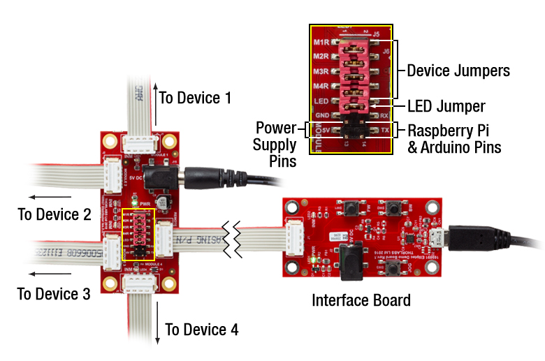
Fourteen control pins, detailed in the image to the right, are included for additional functionality. Four pairs of pins are each shorted with a jumper that, when in place, enables the Elliptec software to receive feedback from connected Elliptec devices. The pair of pins labeled LED is shorted with a jumper that, when removed, will disable the indicator LEDs. The 5V and GND allow an optional, user-provided 5 V, 2 A power supply to be used in place of a source connected to the Ø6.3 mm power connector. The RX and TX pins can be used to control the bus with a Raspberry Pi® or Arduino® board, respectively, instead of the Elliptec interface board.
The board is mounted using the Ø3.5 mm through holes provided in each corner. Four 8-conductor, 28 AWG ribbon cables are included.
| Compatible Elliptec Devices | |||||
|---|---|---|---|---|---|
|
|
|
|
 |
|
| Multi-Position Sliders | 28 mm Linear Stage | 60 mm Linear Stage | Rotation Stage | Rotation Mount | Motorized Iris |