 Products Home / Motion Control Electronics / Piezo / Strain Gauge Controllers / Kinesis® K-Cube™ Piezo Controller and Strain Gauge Reader
Kinesis® K-Cube™ Piezo Controller and Strain Gauge Reader
- Combined Piezo Controller and Strain Gauge Reader
- Closed- or Open-Loop Operation
- Operation via Local Panel Controls or Remote PC via USB
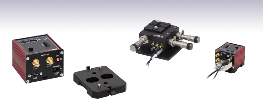
KPC101
Power Supply Sold Separately
Table Mounting Plate
(Included with the KPC101)
Application Idea
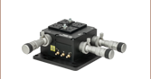
KPC101 Piezo Controller and Strain Gauge Reader Used for Closed-Loop Operation of One of Our 3-Axis Nanopositioning Flexure Stages
MAX311D
3-Axis Nanopositioning Stage (Sold Separately)
KPC101


Please Wait
| K-Cube™ Motion Control Modules |
|---|
| Brushed DC Servo Motor Controller |
| Brushless DC Servo Motor Controller |
| Fiber Alignment Controllers |
| Single- and Four-Channel Piezo Inertia Actuator Controllers |
| PSD Auto Aligner |
| Single-Channel Piezo Controller |
| Single-Channel Combined Piezo Controller and Strain Gauge Reader |
| Solenoid Controller |
| Stepper Motor Controller |
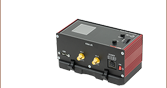
Click to Enlarge
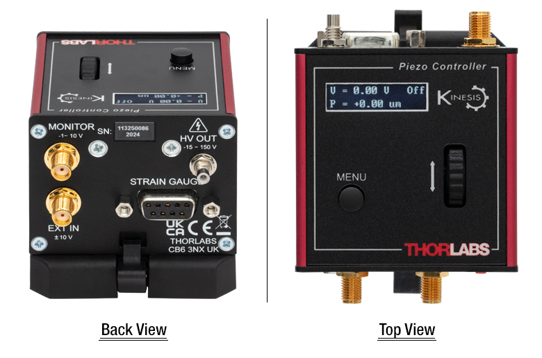
Back and Top Views of the KPC101 K-Cube
(See the Pin Diagrams Tab for More Information)
Features
- Combined Piezo Controller and Strain Gauge Reader
- Compact Footprint: 60.0 mm x 60.0 mm x 47.0 mm
- Closed- or Open-Loop Operation
- Selectable High-Voltage Piezo Drive Output Range: 75 V or 150 V
- On-Unit Control and LCD Display
- Voltage (Open-Loop) and Position (Closed-Loop) Control and Readout
- Force Sensor Readout
- Jogging Functionality with Voltage/Position Presets
- Zeroing and Feedback Mode
- -10 to +10 V Analog Input (SMA Female, See Pin Diagrams Tab for Details)
- Monitor Output (SMA Female, See Pin Diagrams Tab for Details)
- Digital Input and Output Triggers for Piezo Scanning Applications
- Full Kinesis® Software Control Suite (See Kinesis Software Tab for Details)
- Software Compatible with other Kinesis Controllers for Integrated Systems Development
- Single-Channel and Hub-Based Power Supply Options Available Separately
- Multi-Axis Expansion Using USB Controller Hubs (Sold Separately)
- Magnetic, Clip-On Optical Table Mounting Adapter Included
The KPC101 K-Cube Combined Piezo Controller and Strain Gauge Reader is a part of Thorlabs' Kinesis® line of high-end, compact motion controllers. This controller combines the functionality of a high-voltage piezo amplifier and a strain gauge reader, which allows both open-loop and closed-loop control of piezo driven devices. This single-channel controller is compatible with Thorlabs' bare piezo stacks, piezo-equipped actuators, and piezo-driven mirror mounts, as well as piezo-driven single- and multi-axis flexure stages. For mounts with BNC connectors, a BNC to SMC adapter is required. Note that actuators and mounts with piezo inertia motors are not compatible with the KPC101 controller and should be driven with a Piezo Inertia Motor Controller.
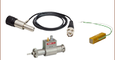
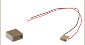
Strain-gauge equipped piezo stacks and actuators (such as Item #s DRV120, DRV517, PAZ005, PAZ009) can be operated in closed-loop for high-precision position control. For compatibility with strain-gauge equipped bare piezos and to amplify small strain-gauge signals, Thorlabs offers the AMP002 Strain-Gauge Pre-Amp Circuit, which includes solder points to connect the four strain-gauge leads and a 9-pin D-sub cable for connecting to the KPC101 K-Cube. Alternatively, the K-Cube can be used with the FSC102 or FSC103 force sensors to provide high-sensitivity force measurements.
The unit has a highly compact 60.0 mm x 60.0 mm x 47.0 mm footprint, allowing it to be positioned close to the motorized system for added convenience when manually adjusting motor positions using the top panel controls. Tabletop operation also allows minimal drive cable lengths for easier cable management. Each unit contains a front-located power switch that, when turned off, saves all user-adjustable settings. Please note that this switch should always be used to power down the unit. For convenience, a 1.5 m long Type A to Type Micro B USB 3.0 cable is included with the KPC101 cube.
Thorlabs designed this K-Cube to encapsulate full piezo control and feedback capability in an extremely small package. To support a wide variety of piezo devices, the output range can be set to 75 V or 150 V with the option to further limit output in software. The resolution of the digitally encoded adjustment pot is easily altered to provide very accurate positioning control. Direct hardware control of the high-voltage output can be facilitated using the -10 to 10 V analog input connector (EXT IN, see Pin Diagrams tab for details). In open-loop mode the input driving voltage on EXT IN directly drives the cube's high voltage amplifier and the output is proportional to the input voltage, while in closed-loop mode this voltage controls the position. In either mode, the voltage present on EXT IN (either positive or negative) is added to the software-defined voltage or position. The low-voltage output connector (MONITOR) allows for easy monitoring of the high-voltage output (e.g., when using an oscilloscope). Programmable waveform generation capability combined with triggering inputs and outputs makes this unit particularly well suited for use in piezo scanning applications.
Embedded software allows this unit to be fully operated using the on-unit menu button, LCD display, and control wheel or using external trigger signals. The unit displays both voltage output (open-loop) and position (closed-loop) read out. In addition to these on-unit controls, USB connectivity provides simple PC-controlled operation with the Kinesis software package.
The Kinesis Software features new .NET controls which can be used by 3rd party developers working in the latest C#, Visual Basic, LabVIEW™ or any .NET compatible languages to create custom applications. For more details on the software package, please see the Kinesis Software tab.
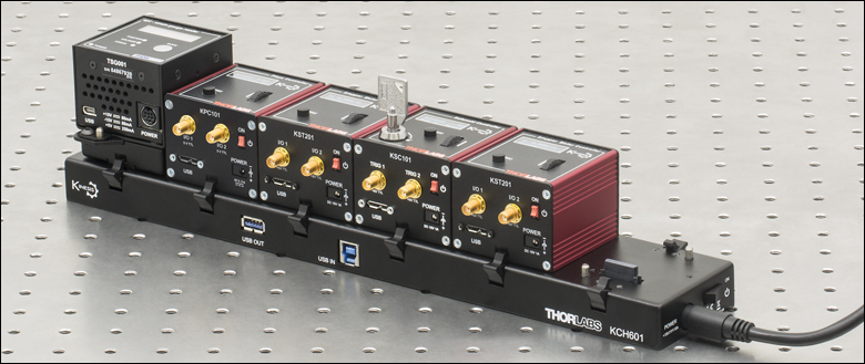
Click to Enlarge
The KCH601 USB Controller Hub with installed K-Cube and T-Cube modules. One KAP101 adapter plate is used for the T-Cube on the hub.
Optical Table Mounting Plate
Each unit comes with a mounting plate that clips onto the base of the controller. The plate contains two magnets for temporary placement on an optical table and two counterbores for 1/4"-20 (M6) cap screws for a more permanent placement on the tabletop. Please see the Specs for a mechanical drawing of the table mounting plate and the Mounting Options tab for how to mount the plate.
Power Supply Options
The preferred power supply (single channel or hub-based) depends on the end user's application and whether you already own compatible power supplies. To that end and in keeping with Thorlabs' green initiative, we do not ship these units bundled with a power supply.
Multiple units can be connected to a single PC by using the KCH301 or KCH601 USB Controller Hubs, available below, for multi-axis motion control applications. The KCH301 allows up to three T- or K-Cube controllers to be used while the KCH601, shown to the right, allows up to six controllers to be used.
All power supply options compatible with the KPC101 Piezo-Strain Controller can be found below.
| Other Piezo Controllers | ||||
|---|---|---|---|---|
| K-Cube Combined Piezo Controller and Strain Gauge Reader Single-Channel |
K-Cube Piezo Controller Single-Channel |
Open Loop Benchtop Controller 1- and 3-Channel |
Closed Loop Benchtop Controller 1- and 3-Channel |
Rack System Module 2-Channel |
| KPC101 Specifications | |
|---|---|
| Piezoelectric Output | |
| Control Mode | Open Loop (Voltage) or Closed Loop (Position) |
| Piezo Drive Voltage | -10 to +150 V Max (SMC Connector) |
| Piezo Drive Current | ±12 mA Continuous |
| Output Noise | <1 mVrms |
| Typical Piezo Load Capacitance | 1 to 10 µF |
| Unit Internal Capacitance | 100 nF |
| Output Impedance | 15 Ω |
| Drive Bandwidth | 1 kHz (1 µF Load, 1 Vp-p) |
| Drive Input (EXT IN) | ±10 V (SMA Connector) |
| Output Monitor (MONITOR) | -1 to +10 V (SMA Connector) |
| K-Cube Controller Hub Connector | 26-Way ERNI |
| Input Power Requirements | |
| Supply Voltage | 15 VDC |
| Supply Current | 130 mA at Output Current = 0 mA 250 mA at Output Current = 13 mA |
| Compatible Power Suppliesa | Item #s KPS201, KCH301, KCH601 |
| General Data | |
| USB Connector Type | USB 3.0 |
| USB Connection Speed | USB 1.1 Full Speed (12 Mbps) |
| Display Type | 128 x 32 Pixel LCD |
| Weight (Including Baseplate) | 0.21 kg (0.46 lbs) |
| Housing Dimensionsb (W x D x H) |
60.0 mm x 60.0 mm x 47.0 mm (2.36" x 2.36" x 1.85") |
| Compatible Thorlabs Stages, Actuators, and Force Sensors | |
|---|---|
| Translation Stages | 3-Axis and 6-Axis Nanopositioners, NF15AP25, NFL5DP20, NFL5DP20S |
| Piezo Controlled Mountsa | KC1-P, KC1-PZ, POLARIS-K05P2, POLARIS-K1S3P, POLARIS-K1S2P, POLARIS-K2S2P |
| Bare Piezosb | Piezo Chips and Stacks with Drive Voltages up to 150 V |
| Actuators | DRV120, PE4a, DRV517, PK2FSF1, PK2FVF1, PAS005, PAS009, PAZ005, PAZ009 |
| Force Sensors | FSC102 and FSC103 |
Click to Enlarge
Mechanical Drawing of the KPC101 and Included Optical Table Adapter
Click to Enlarge
Click Here for Raw Data
Drive Voltage/Frequency Response at Different Capacitive Loads for the KPC101 Controller
Strain Gauge I/P Connector
D-Type Female
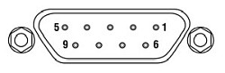
| Pin | Description | Pin | Description |
|---|---|---|---|
| 1 | Wheatstone Bridge Excitation | 5 | AC Feedback IN |
| 2 | +15 V Outa | 6 | Ground |
| 3 | -15 V Outa | 7 | Actuator ID Signalb |
| 4 | Ground | 8 & 9 | Reserved for Future Use |
Computer Connection*
*The USB 3.0 port is compatible with a USB 2.0 Micro B connector if the Micro B connector is plugged into the shaded region in the photo above. A USB 3.0 type A to type Micro B cable is included with the KPC101.
Monitor
SMA Female
This low-voltage (-1 to +10 V) output can be used to monitor the signal at the HV OUT high-voltage output. In its most common use, it can be connected directly to an oscilloscope to observe the waveforms or voltage levels present at the high-voltage output.
EXT IN
SMA Female
Used to connect an external analog signal source to control the operation of the K-cube. The input voltage range is ±10 V and the input impedance is 32 kΩ.
HV OUT
SMC Male

-15 to 150 V, ±13 mA. Provides the drive signal to the piezo actuator. The maximum voltage (75 V or 150 V) is set via the Kinesis GUI.
I/O 1
SMA Female
+5 V TTL
I/O 2
SMA Female
+5 V TTL
These connectors provide a 5 V logic level input and output that can be configured to support triggering into and out of external devices. Each port can be independently configured to control the logic level or to set the trigger as an input or output.
K-Cube Mounting Options
Two options are available to securely mount our K-Cube controllers onto an optical table. An optical table mounting plate, provided with every K-Cube, allows for a single controller to be attached to an optical table. Alternatively, three- and six-port USB controller hubs are offered (sold separately) that can mount and power our K-Cube controllers. These options are described in further detail below.
Optical Table Mounting Plate
Each K-Cube unit comes with a mounting plate that clips onto the base of the controller, as shown in the animation to the right. The plate contains two magnets for temporary placement on an optical table and two counterbores for 1/4"-20 (M6) cap screws for a more permanent placement on the tabletop. Please see the Specs tab for a mechanical drawing of the table mounting plate.
Kinesis USB Controller Hubs
Multiple units can be mounted and connected to a single PC by using the KCH301 or KCH601 USB Controller Hubs. They each consist of two parts: the hub, which can support up to three (Item # KCH301) or six (Item # KCH601) K-Cubes or T-Cubes, and a power supply that plugs into a standard wall outlet. K-Cubes simply clip into place using the provided on-unit clips, while current- and previous-generation T-Cubes require the KAP101 Adapter Plate, shown in the animation below. The hub vastly reduces the number of USB and power cables required when operating multiple controllers.
K-Cube Table Mounting Plate
Unlike T-Cubes, every K-Cube includes a mounting plate that clips onto the base of the controller. The plate contains two magnets for temporary placement on an optical table and two counterbores for 1/4"-20 (M6) cap screws for more permanent placement on the tabletop.
Kinesis USB Controller Hubs
3- and 6-Port USB Controller Hubs allow multiple controllers to be connected to one PC for multi-axis applications. K-Cubes can be directly attached to the hubs while T-Cubes require a KAP101 Adapter Plate.

Click for Details
Piezo Controller as Part of a Closed-Loop System
Piezo Controller in a Beam Stabilization Setup
Active beam stabilization is often used to compensate for beam drift (unintended beam pointing deviations) in experimental setups. Drift can be caused by insecurely mounted optics, laser source instabilities, and thermal fluctuations within an optomechanical setup. In addition to correcting for setup errors, active stabilization is frequently used in laser cavities to maintain a high output power or used on an optical table to ensure that long measurements will take place under constant illumination conditions. Setups with long beam paths also benefit from active stabilization, since small angular deviations in a long path will lead to significant displacements downstream.
An example of a beam stabilization setup is shown in the schematic to the left. A beamsplitter inserted in the optical path sends a sample of the beam to a quadrant position sensor that monitors the displacement of the beam relative to the detector's center. (For optimal stabilization, the beamsplitter should be as close as possible to the measurement.) The quadrant detector outputs an error signal in X and Y that is proportional to the beam's position. Each error signal is fed into a channel of a piezoelectric controller that steers the beam back to the center of the quadrant sensor.
The setup illustrated here stabilizes the beam to a point in space. In order to stabilize the beam over a beam path, four independent output channels are required (i.e., at least two piezoelectric controllers), as are two mirror mounts with piezo adjusters, two position sensors, and two position sensor controllers. Suggested electronics for a beam stabilization setup are given in the table below.
| Suggested Components | |
|---|---|
| Description | Item # |
| Piezoelectric Controller | KPC101 K-Cube Piezo Controller and Strain Gauge Readera |
| Mirror Mount with Piezo Adjusters (Choose One) |
POLARIS-K1S3P Polaris® Mirror Mount with 3 Adjusters, POLARIS-K1S2P Polaris® Mirror Mount with 2 Adjusters, KC1-PZ (KC1-PZ/M) Mirror Mount, or KC1-T-PZ (KC1-T-PZ/M) Mirror Mount with SM1-Threaded Bore |
| Position Detector | PDP90A (320 - 1100 nm), PDQ80A (400 - 1050 nm), or PDQ30C (1000 - 1700 nm) |
| K-Cube Position Sensor Controller | KPA101 |
Thorlabs' Kinesis® software can be used to control devices in the Kinesis or APT™ family, which covers a wide range of motion controllers ranging from small, low-powered, single-channel drivers (such as the K-Cubes and T-Cubes) to high-power, multi-channel, modular 19" rack nanopositioning systems (the APT Rack System).
The Kinesis Software features new .NET controls which can be used by 3rd party developers working in the latest C#, Visual Basic, LabVIEW™ or any .NET compatible languages to create custom applications. Low level DLL libraries are included for applications not expected to use the .NET framework. A Central Sequence Manager supports integration and synchronization of all Thorlabs motion control hardware.
By providing these common software platforms, Thorlabs has ensured that users can easily mix and match any of the APT and Kinesis controllers in a single application, while only having to learn a single set of software tools. In this way, it is perfectly feasible to combine any of the controllers from the low-powered, single-axis to the high-powered, multi-axis systems and control all from a single, PC-based unified software interface.
The software packages allow two methods of usage: graphical user interface (GUI) utilities for direct interaction with and control of the controllers 'out of the box', and a set of programming interfaces that allow custom-integrated positioning and alignment solutions to be easily programmed in the development language of choice.
Software
Kinesis Version 1.14.47
The Kinesis Software Package, which includes a GUI for control of Thorlabs' Kinesis and APT™ system controllers.
Also Available:
- Communications Protocol
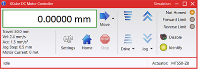
Kinesis GUI Screen
Thorlabs' Kinesis® software features new .NET controls which can be used by third-party developers working in the latest C#, Visual Basic, LabVIEW™, or any .NET compatible languages to create custom applications.
C#
This programming language is designed to allow multiple programming paradigms, or languages, to be used, thus allowing for complex problems to be solved in an easy or efficient manner. It encompasses typing, imperative, declarative, functional, generic, object-oriented, and component-oriented programming. By providing functionality with this common software platform, Thorlabs has ensured that users can easily mix and match any of the Kinesis controllers in a single application, while only having to learn a single set of software tools. In this way, it is perfectly feasible to combine any of the controllers from the low-powered, single-axis to the high-powered, multi-axis systems and control all from a single, PC-based unified software interface.
The Kinesis System Software allows two methods of usage: graphical user interface (GUI) utilities for direct interaction and control of the controllers 'out of the box', and a set of programming interfaces that allow custom-integrated positioning and alignment solutions to be easily programmed in the development language of choice.
For a collection of example projects that can be compiled and run to demonstrate the different ways in which developers can build on the Kinesis motion control libraries, click on the links below. Please note that a separate integrated development environment (IDE) (e.g., Microsoft Visual Studio) will be required to execute the Quick Start examples. The C# example projects can be executed using the included .NET controls in the Kinesis software package (see the Kinesis Software tab for details).
 |
Click Here for the Kinesis with C# Quick Start Guide Click Here for C# Example Projects Click Here for Quick Start Device Control Examples |
|
LabVIEW
LabVIEW can be used to communicate with any Kinesis- or APT-based controller via .NET controls. In LabVIEW, you build a user interface, known as a front panel, with a set of tools and objects and then add code using graphical representations of functions to control the front panel objects. The LabVIEW tutorial, provided below, provides some information on using the .NET controls to create control GUIs for Kinesis- and APT-driven devices within LabVIEW. It includes an overview with basic information about using controllers in LabVIEW and explains the setup procedure that needs to be completed before using a LabVIEW GUI to operate a device.
 |
Click Here to View the LabVIEW Guide Click Here to View the Kinesis with LabVIEW Overview Page |
|
| Posted Comments: | |
| No Comments Posted |

 Zoom
Zoom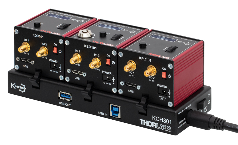
Click to Enlarge
KCH301 USB Controller Hub (Sold Separately) with Installed K-Cube Modules
- Control Panel and LCD Screen for On-Unit Control
- Closed-Loop Position or Open-Loop Voltage Control and Readout
- Interfaces with Computer Using Included USB Cable
- Fully Compatible with Kinesis® Software Package
- Compact Footprint: 60.0 mm x 60.0 mm x 47.0 mm
- Power Supply Not Included (See Below)
The KPC101 Combined Piezo Controller and Strain Gauge Reader drives piezo stacks and actuators with up to 150 V of drive voltage. Featuring a built-in strain-gauge reader, the combined controller is capable of precision closed-loop position control of strain-gauge equipped piezos with up to 1 nm readout using the Kinesis software. The top-mounted control panel with velocity wheel supports three speeds of forward and reverse jogging as well as voltage or position presets. The front of the unit contains two bidirectional trigger ports (I/O) that can be used to read a 5 V external logic signal or output a 5 V logic signal to control external equipment. Each port can be independently configured to control the logic level or to set the trigger as an input or output.
The unit is fully compatible with our Kinesis software package. Please see the Kinesis Software tab for more information.
Please note that this controller does not ship with a power supply. Compatible power supplies are listed below.

 Zoom
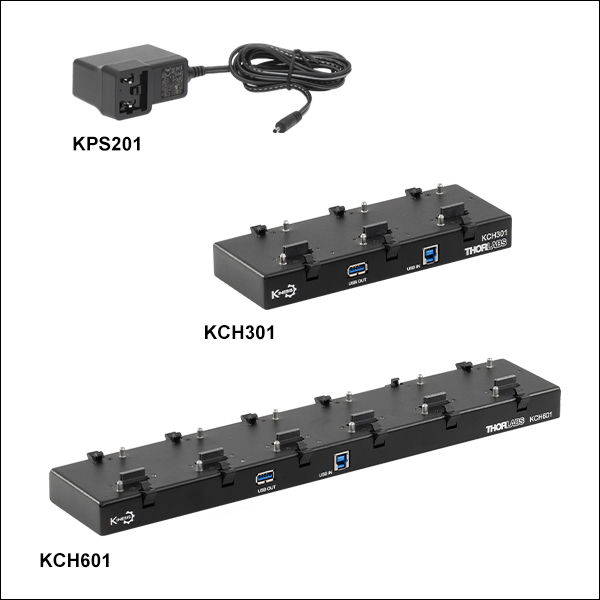
Zoom- individual Power Supply
- KPS201: For K-Cubes™ or T-Cubes with 3.5 mm Jacks
- USB Controller Hubs Provide Power and Communications
- KCH301: For up to Three K-Cubes or T-Cubes
- KCH601: For up to Six K-Cubes or T-Cubes
The KPS201 power supply outputs +15 VDC at up to 2.66 A and can power a single K-Cube or T-Cube with a 3.5 mm jack. It plugs into a standard wall outlet.
The KCH301 and KCH601 USB Controller Hubs each consist of two parts: the hub, which can support up to three (item # KCH301) or six (item # KCH601) K-Cubes or T-Cubes, and a power supply that plugs into a standard wall outlet. The hub draws a maximum current of 10 A; please verify that the cubes being used do not require a total current of more than 10 A. In addition, the hub provides USB connectivity to any docked K-Cube through a single USB connection.
For more information on the USB Controller Hubs, see the full web presentation.