 Products Home
滑动式多孔安装座,带谐振压电电机
- Mount Multiple SM05- or SM1-Threaded Components
- Open Frame Design for OEM Applications
- Control via Interface Board, GUI, or ASCII Message Calls
- Fully Integrated Drive Electronics
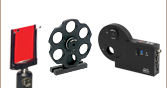
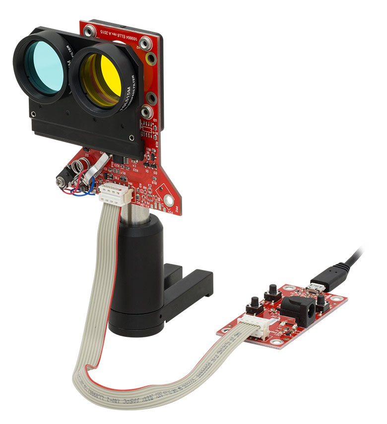
Application Idea
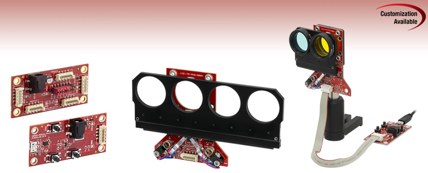
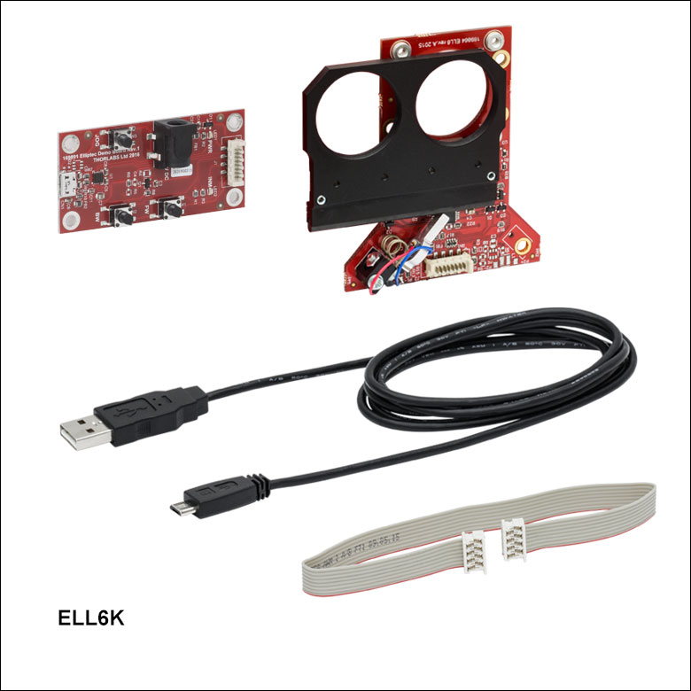
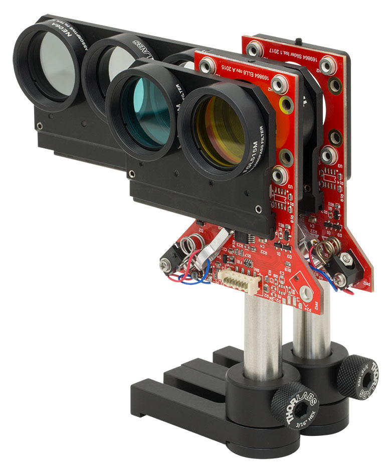
ELL6K Bundle Components Shown Assembled, with Two Colored Glass Filters, and Mounted Using the ELLA1 Adapter
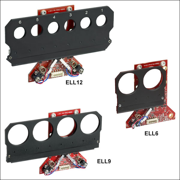
Four-Position Slider
(Also Available Individually)
Interface Board
ELL9K
Four-Position
Slider Bundle
(Board and Slider Included)
ELLB
Bus Distributor


Please Wait
| Key Specsa | |||
|---|---|---|---|
| Item # | ELL12(K) | ELL6(K) | ELL9(K) |
| Ports for Mounted Optics | Six, SM05 Threaded | Two, SM1 Threaded | Four, SM1 Threaded |
| Switching Time Range | No Load: 350 to 400 ms 150 g Load: < 600 ms | No Load: 180 to 270 ms 100 g Load: < 600 ms | No Load: 450 to 500 ms 150 g Load: < 700 ms |
| Positioning Repeatability | < 100 µm (30 µm Typical) | ||
| Maximum Total Loadb | 150 g (5.29 oz) | ||
| DC Voltage Input | 4.5 to 5.5 V | ||
| Weight (Slider Only) | 78.5 g (2.77 oz) | 44.0 g (1.55 oz) | 70.0 g (2.47 oz) |
| Minimum Lifetimec | 3.3 Million Operations or 100 km Total Travel | ||
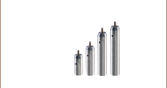
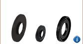
| Elliptec Resonant Motor Products | |||||
|---|---|---|---|---|---|
 |  |  |  |  |  |
| Multi-Position Sliders | 28 mm Linear Stage | 60 mm Linear Stage | Rotation Stage | Rotation Mount | Motorized Iris |
 Thorlabs Elliptec OEM技术
视频展示了使用30 mm笼式系统组件安装滑动式多孔安装座并通过接口板操作ELL6K的过程。ELLA1(下方提供)是另一种安装选项。更多有关操作这些器件的信息,请看操作标签。该视频清楚地展示了滑块的缓慢移动。
特性
- 非常适合OEM和需要快速切换的应用
- Micro-B USB和Picoflex®1接头,用于控制信号
- 支持多点串行通信协议
- SM05或SM1螺纹端口,用于已安装的光学元件或其他组件
- 光斩波器光学传感器技术,用于位置的精确对准
- 兼容30 mm笼式系统组件
- 下方提供总线分配器、接杆安装转接件和配件升级包
滑动式多孔安装座由Thorlabs的Elliptec®压电谐振电机技术驱动,能够实现毫秒级切换时间。每个滑动式安装座既可以单独提供,又可以作为套件(包含接口板)中的部件提供。Thorlabs还提供配件包,用于将独立装置升级为完整套件。滑动式多孔安装座结构紧凑,重量轻,且都使用定制设计的相同PCB,ELL6包含一个电机,ELL12和ELL9包含两个电机。这些电机动力强,没有传动装置。电机内没有磁铁,可以在电磁敏感的环境中使用。更多信息,请看Elliptec®电机标签。
这些安装座开放型的框架模式,清晰明了的结构和灵活的适应能力,使其非常适合OEM应用,我们可以根据客户的要求进行定制并大批量生产。更多信息,请看OEM和制造能力页面。
控制
给这些滑动式多孔安装座供电、驱动并控制它们的方法有多种,这在操作标签的操作滑动式安装座的部分有详细描述。每个安装座都具有3.3 V串行总线,有无接口板都可以工作;有关引脚分布,请看引脚图标签。Thorlabs提供用于我们Elliptec产品的软件,以便实现对安装座的全方位独立控制。当接口板用作配件来改变安装座上滑块的位置时,软件会自动更新滑块的状态。请注意,滑动式双孔和四孔安装座不适用于连续工作。我们建议在占空比为40%以下时运行。
可以使用ELLB总线分配器或将多个接头接到一根带状电缆上以控制多个Elliptec设备。一个总线分配器最多可以连接四个Elliptec装置。如果总线以菊花链连接,则最多可以连接16个装置。可以通过以下三种方式控制此总线:通过接口板(包含在以下套件中)连接至运行Elliptec软件的PC、连接到Arduino®2或Raspberry Pi®3板,或通过接头引脚接线到用户提供的控制板上。 另外,一条带状电缆最多可以接16个装置。然后可以通过接口板同时控制这些装置,或者可以通过Elliptec软件选择性地控制。有关自定义连接时如何分配引脚请查看引脚图标签,了解如何将多个装置接到带状电缆上请查看手册。
应用想法
滑动式多孔安装座非常适合用作滤光片转换器,ELL6也适合用作快门。它们的滑块有SM05或SM1螺纹孔,螺纹深度3.5 mm,结构PCB还有四个4-40螺孔,低剖面的ELLA1接杆安装转接件(下方提供)可以安装在滑动式安装座上,集成到使用Thorlabs 30 mm笼式系统组件的光学装置中。对于需要在SM05螺纹滤光片之间切换的水平空间有限的应用,Thorlabs提供兼容ELL18旋转位移台的SM05螺纹滤光片转轮转接件。
- Picoflex是Molex Incorporated的注册商标。
- Arduino是Arduino Sa Société Anonym (SA)的注册商标。
- Raspberry Pi是Raspberry Pi Foundation的注册商标。
规格
当滑动式多孔安装座按操作标签中推荐的方法安装时的性能规格。
| Item # | ELL12(K) | ELL6(K) | ELL9(K) | |
|---|---|---|---|---|
| Performance | ||||
| Switching Time between Adjacent Positions | Unloaded Carriage on Slider | 350 to 400 ms | 180 to 270 ms | 450 to 500 ms |
| Loaded Carriage on Slider | < 600 ms (150 g Load) | < 600 ms (100 g Load) | < 700 ms (150 g Load) |
|
| Thread Type of Ports in Carriage | Internal SM05 (0.535"-40)a Threads, 3.5 mm Deep | Internal SM1 (1.035"-40)a Threads, 3.5 mm Deep | ||
| Number of Threaded Ports in Carriage | Six | Two | Four | |
| Travel | 95 mm (3.74") | 31 mm (1.22") | 93 mm (3.66") | |
| Positioning Repeatabilityb | < 100 µm (30 µm Typical) | |||
| Maximum Total Load (Vertically Mounted)c | 150 g (5.29 oz) | |||
| Minimum Lifetimed | 3.3 Million Switching Operations or 100 km Total Travel | |||
| Electrical | ||||
| DC Voltage Input | 4.5 to 5.5 V | |||
| Typical Current Consumption | During Movement | < 1200 mA | < 600 mA | < 1200 mA |
| During Standby | 38 mA | |||
| During Search for Resonant Frequenciese | 1.2 A | |||
| Communications | ||||
| Busf | Multi-Drop 3.3 V/5 V TTL RS232 | |||
| Connector on Multi-Position Slider Board | Picoflex® | |||
| Connectors on Interface Board | Picoflex® Micro-B USB 5 VDC Power: [For Plug with Ø5.5 mm OD (Ground) and Ø2.1 mm ID (+5 V)] | |||
| Speed | 9600 baud/s | |||
| Data Lengthg | 8 bit | |||
| Protocol Data Format | ASCII HEX | |||
| Module Address and Command Format | Mnemonic Character | |||
| 8-Conductor Ribbon Cable Length | Supplied: 0.250 m; Max: 3 m | |||
| Mechanical | ||||
| Dimensions of the Slider (At End Stops)h | 143.5 mm x 77.7 mm x 14.2 mm (5.65" x 3.06" x 0.56") | 80.5 mm x 77.7 mm x 14.9 mm (3.16" x 3.06" x 0.59") | 143.5 mm x 77.7 mm x 14.9 mm (5.65" x 3.06" x 0.59") | |
| Dimensions of the Interface Board | 32.0 mm x 66.0 mm x 12.5 mm (1.26" x 2.60" x 0.49") | |||
| Weight (Slider) | 78.5 g (2.77 oz) | 44.0 g (1.55 oz) | 70.0 g (2.47 oz) | |
| Weight (Interface Board) | 10.3 g (0.36 oz) | |||
| Environmental Operating Conditions | ||||
| Temperature Range | 15 to 40 °C | |||
| Maximum Relative Humidity (Non-Condensing) | < 80% at 31 °C | |||
| Maximum Altitude | 2000 m | |||
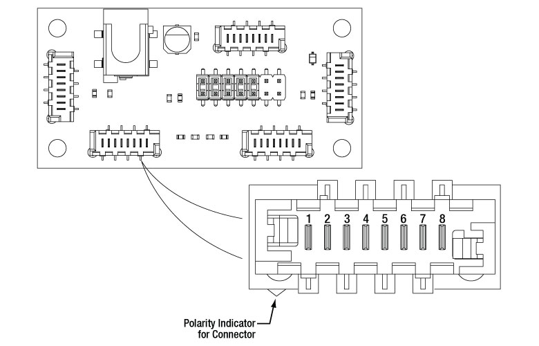
| ELL12 & ELL9 Connector J2 Pinouta,b | ||
|---|---|---|
| Pin | Type | Function |
| 1 | PWR | Ground |
| 2 | OUT | OTDX - Open Drain Transmit 3.3 V TTL RS232 |
| 3 | IN | RX Receive 3.3 V TTL RS232 |
| 4 | OUT | In Motion, Open Drain Active Low Max 5 mA |
| 5 | IN | JOG/Mode, Active Low Max 5 V |
| 6 | IN | BW Backward, Active Low Max 5 V |
| 7 | IN | FW Forward, Active Low Max 5 V |
| 8 | PWR | VCC +5 V ± 10%; 1200 mA |
| ELL6 Connector J2 Pinouta,b | ||
|---|---|---|
| Pin | Type | Function |
| 1 | PWR | Ground |
| 2 | OUT | OTDX - Open Drain Transmit 3.3 V TTL RS232 |
| 3 | IN | RX Receive 3.3 V TTL RS232 |
| 4 | OUT | In Motion, Open Drain Active Low Max 5 mA |
| 5 | IN | JOG/Mode = Normal/Test Demo, Active Low Max 5 V |
| 6 | IN | BW Backward, Active Low Max 5 V |
| 7 | IN | FW Forward, Active Low Max 5 V |
| 8 | PWR | VCC +5 V ± 10%; 600 mA |
| ELLB Connector J1, J2, J3, and J4 Pinouta,b | ||
|---|---|---|
| Pin | Type | Function |
| 1 | PWR | Ground |
| 2 | OUT | OTDX - Open Drain Transmit 3.3 V TTL RS232 |
| 3 | IN | RX Receive 3.3 V TTL RS232 |
| 4 | OUT | In Motion, Open Drain Active Low Max 5 mA |
| 5 | IN | Not Connected |
| 6 | IN | Not Connected |
| 7 | IN | Not Connected |
| 8 | PWR | VCC +5 V ± 10%; 800 mA per Connected Device |
操作注意事项
该标签包含操作、安装和这些滑动式多孔安装座的工作。
内容
Click to Enlarge
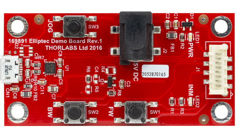
图2 接口板
操作
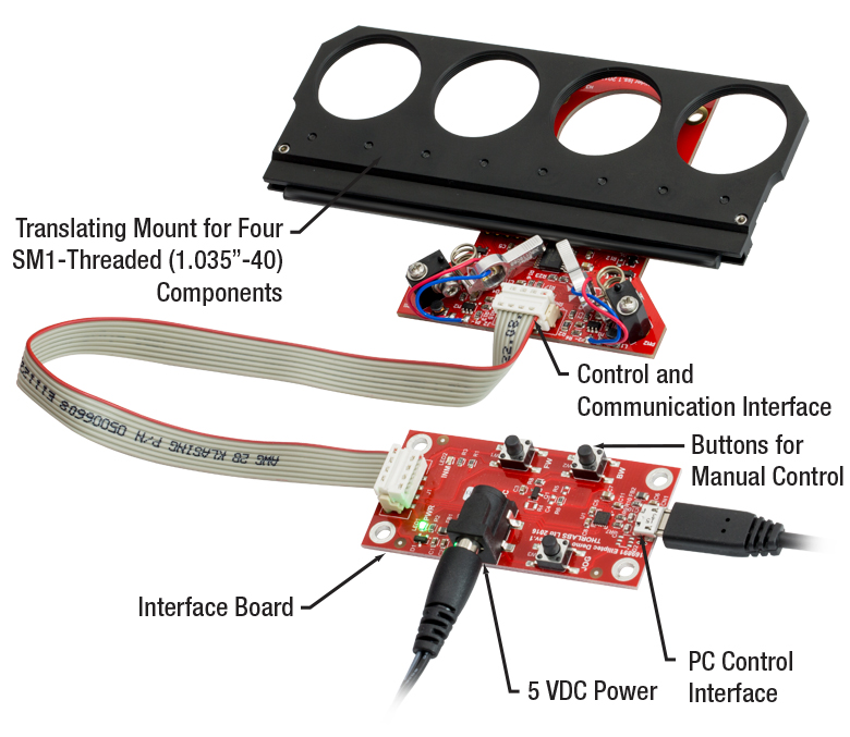
我们的滑动式多孔安装座和接口板非常坚稳,足以应对一般操作。图1中标记出了ELL9K套件的关键组成部分,图2为接口板的图片。为了确保运行可靠,与电机接触的表面不要沾染油、污垢和灰尘。拿取双孔或四孔安装座时无需戴手套,但是要避免触摸与电机接触的表面,防止其沾染指纹上的油污。如需清洗与电机接触的表面,可以使用沾有异丙醇或矿物溶剂(石油溶剂)的KW32或其他超低绒毛的纸擦拭。但是不要使用丙酮,因为这种溶剂会破坏安装座的塑料边缘。
这些安装座的开放式框架结构可耐受高达8 kV的静电放电,但应采取ESD预防措施,因为静电放电会可能产生引起位移台意外移动的电气信号。避免让结构PCB承受超过500 g的负载。如果过载,PCB可能会弯折,这会损害安装座的性能。
安装
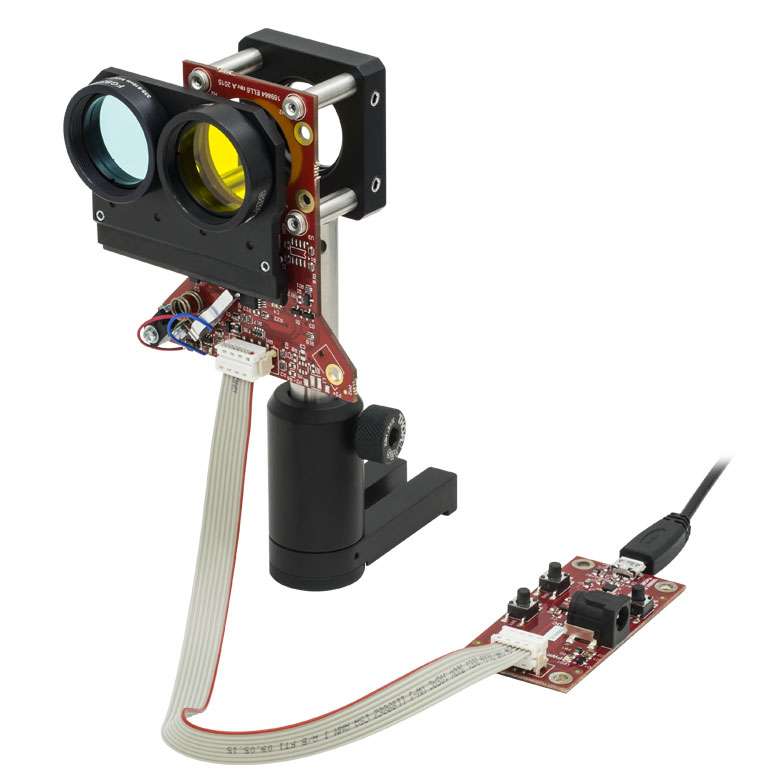
在适当条件下操作滑动式多孔安装座,使滑块能在垂直(正置)或水平面(放平)移动。当竖直安装滑动式安装座时,滑动板就会左右移动,而不是上下移动,这是由于重力效应显著减少了可移动的最大负载。竖直安装时,电机可安装在滑动板的上方或者下方;但是,建议将电机安装在滑动板的下方,如图3-7所示,这样可以最大程度地减少在工作过程中灰尘或微粒落到滑动板中光学元件表面的几率。当安装座水平安装时,要保证安装不会使PCB弯曲。总之,要保证滑动式多孔安装座的移动部分不会受到干扰。
安装滑动式安装座的方法有几种。下方出售的ELLA1接杆安装转接件可以直接安装在安装座PCB的背面。如图3所示,然后可以利用转接件将安装座安装到Ø1/2英寸接杆。ELLA1的尺寸紧凑,以便将多个安装座前后放置,同时最大程度地减少安装座之间的间距,如下图所示。该转接件还可以与Thorlabs的30 mm笼式系统组件和/或SM1螺纹组件集成(比如透镜套管)。另外,也可以单独使用30 mm笼式系统组件安装安装座。如图4中示例,使用了CP33笼板、四根ER1支杆和Ø1/2英寸接杆和接杆支架来安装和支撑组装的ELL6K。
负载
150 g的最大总负载规格是指安装在滑动板上的负载重量,并不包括安装座的重量。例如,无负载ELL6安装座重量约为22 g,安装光学元件所允许的最大重量为150 g;安装座与光学元件的最大总重量为172 g。两种安装座都兼容30 mm笼式系统组件。
供电
使用接口板
虽然需要超声电压信号来操作电机,但可通过给接口板施加直流电压信号来给安装座供电。接口板上的电子装置可将施加的直流信号转变为以指定谐振频率振荡的正弦信号,从而实现这种可能。
ELL6包含一个电机,ELL12和ELL9包含两个电机。由于ELL6单个电机的功率要求较低,因此可以通过接口板的Micro-B USB接头给ELL6供电。ELL6K套件中不附带5 V电源。两个电机的操作需要5 V电源,所以ELL12K和ELL9K套件中附带了一个这样的电源。
使用接口板上Micro-B USB接头给ELL6供电的优势在于可以通过计算机同时控制并给安装座供电。笔记本电脑可以提供使ELL6滑动式双孔安装座切换位置的电流强度;但是,有些笔记本无法提供寻找最佳谐振频率所需的1.2 A电流,这点在下面的谐振频率部分有提到。在这种情况下,为了寻找最佳谐振频率,就必须使用其他可以供应所需电流强度的电源,以补充笔记本提供的功率。
装置中包含ELL12和ELL9和接口板时,可以通过5 VDC电源插座供电。由于Micro-B USB接头无法提供驱动两个电机的功率,因此该接头只适合用于安装座的计算机控制。
不使用接口板
当这写安装座集成到没有接口板的应用中时,使用Picoflex接头上的引脚实现与电源的连接。该接头的引脚图包含在引脚图标签中,关于滑动式安装座的功率和寻址分别在手册和通信协议手册中有给出。
电机的工作
Elliptec电机能够移动滑动板,从而切换光学元件的位置。移动方向由驱动电机中压电元件的超声频率决定。对于每个电机,都有一个超声谐振频率使滑动板向前移动,还有一个超声谐振频率使滑动板向后移动。当电机以它的一个谐振频率工作时,会使电机的顶端以一个紧凑的顺时针椭圆路径不断循环运动,而当电机在它的其他谐振频率下工作时,电机的顶端以相同的路径按逆时针方向循环。两个谐振频率在100 kHz左右,电机顶端的总位移与其驱动的机械负载和施加给压电元件的电压具有函数关系。在没有负载时,以一种谐振频率在5 V的最大驱动电压下,电机顶端追迹椭圆路径的扩展和收缩在几微米之内。更多信息,请查看Elliptec®电机 标签以及描述电机工作的视频。
谐振频率
通电时,出厂默认设置会指令安装座搜索可以产生最佳性能的谐振频率。在此过程中,安装座会在前后位置间移动。该校准过程结束时,安装座处于向后的位置。如果启动时不需要这个运动,可以在通电时利用串行端口预置频率,便可不用执行该校准程序。任何时候都可以进行最佳谐振频率的新搜索;为了保持最佳性能,建议负载和/或环境温度发生变化后执行新搜索。请看手册的Section 4.4了解详情。
操作滑动式安装座
请注意,我们的滑动式多孔安装座不适合持续工作。一般使用过程中,我们建议在占空比为40%以下时进行操作,占空比高于60%的操作应该限制在几秒钟之内。
按下接口板上的按钮,通过Elliptec®软件包(可下载)经计算机可以控制安装座滑动板的移动,这也可以通过给滑动板上的数字线路发送简单的信号来实现。恒定的驱动功率产生线性速度曲线,使电机能够在几微秒内加速和减速。
通过Elliptec软件连接安装座时,可以将该接口板当作配件使用;所有因按压接口板上的按钮导致滑动板位置的变化都会记录在软件上,连接接口板时,软件也可独立控制滑动板。图2中可以看到接口板上的按钮。
通可以使用ELLB总线分配器或将多个接头接到一根带状电缆上以控制多个Elliptec设备。一个总线分配器最多可以连接四个Elliptec装置。如果总线以菊花链连接,则最多可以连接16个装置。可以通过以下三种方式控制此总线:通过接口板(包含在以下套件中)连接至运行Elliptec软件的PC、连接到Arduino®或Raspberry Pi®板,或通过接头引脚接线到用户提供的控制板上。 另外,一条带状电缆最多可以接16个装置。然后可以通过接口板同时控制这些装置,或者可以通过Elliptec软件选择性地控制。有关自定义连接时如何分配引脚请查看引脚图标签,了解如何将多个装置接到带状电缆上请查看手册。通信协议手册里面描述了使用软件单独控制每个连接的设备的方法。软件标签中包含下载软件和附带文档的链接。
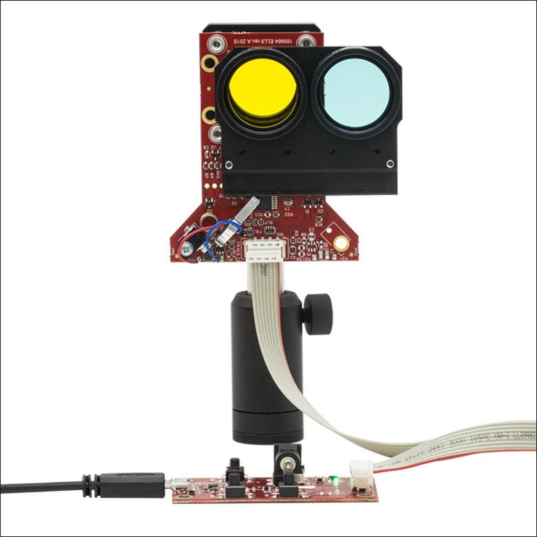
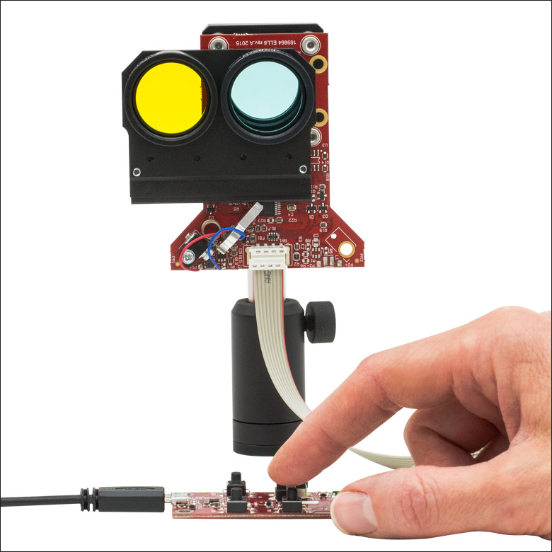
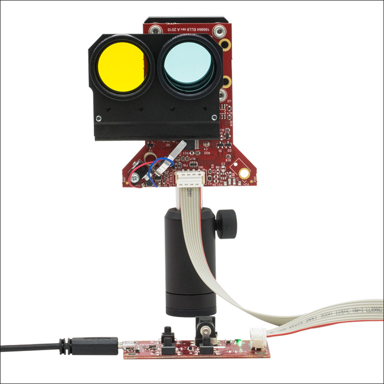
图5 - 7以及概述标签中的视频展现了ELL6滑动式双孔安装座使用接口板工作的过程。按下接口板上标有"FW"的按钮,如图6所示,滑动安装座就移向前面的位置。按下接口板上标有"BW"的按钮,滑动安装座就回到了初始位置。
使用接口板控制ELL12或ELL9四孔安装座上滑动板的位置时,也可以使用JOG按钮。如果滑动板面朝前,在竖直方向,电机在安装座下方,按住JOG按钮并按下FW按钮,将滑动板移动到观察者的右侧。按住JOG按钮并按下BW按钮,将滑动板移动到观察者的左侧。换句话说,参考规格标签底部的图纸,前者增加了滑动板的位置,后者减少了滑动板的位置。
Click to Enlarge
图7 滑动式双孔安装座的滑动板处于前面位置
Click to Enlarge
图5 滑动式双孔安装座的滑动板处于后面位置
ELL12K和ELL9K滑动式安装座套件
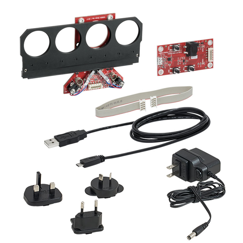
每个套件包含以下物品:
- 滑动式安装座
- 接口板
- Micro-B转A型USB电缆
- 8线的28 AWG带状电缆
- 5 V电源,带符合当地区域的插头
基于PC的软件可以下载,请参考手册、通信协议手册及其他文献。
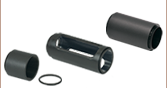
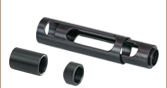
ELL6K滑动式安装座套件

Click to Enlarge
ELL6K套件中的元件
每个套件包含以下物品:
- 滑动式安装座
- 接口板
- Micro-B转A型USB电缆
- 8线的28 AWG带状电缆
基于PC的软件可以下载,请参考手册、通信协议手册及其他文献。
Click to Enlarge
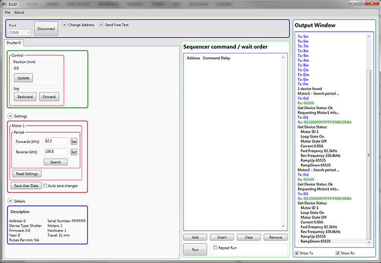
Elliptec压电谐振电机控制软件GUI
用于Elliptec®压电谐振电机的软件
所有基于Elliptec®谐振压电电机的装置都可以由Elliptec系统软件控制,该软件有一个直观的图形用户界面(GUI)。软件包中包含C#格式的源代码,可以下载,也可以用任何语言创造自定义应用。右图显示了GUI的屏幕截图,以及可以链接到下载页面的按钮。
可将命令输入位于GUI中间偏左的命令序列/等待命令(Sequencer command / wait order )区域。例如,可将命令序列输入装置,让"Afw"表示将安装座从地址"A"移动到前面位置,"Abw"表示将安装座从地址"A"移动到后面位置。命令"As1"用来执行频率搜索,识别在当前工作条件下电机在地址"A"的最佳谐振频率。
软件
版本 1.6.3
包含Elliptec系统软件,带有一个方便使用的GUI。同时还有一个可以下载的通信协议手册,描述了Elliptec软件包的通信命令。
| SM05 Threading: Ø1/2" Lens Tubes, 16 mm Cage Systems | |||
|---|---|---|---|
| External Thread, 0.535"-40.0 UNS-2A | Internal Thread, 0.535"-40.0 UNS-2B | ||
| Max Major Diameter | 0.5340" | Min Major Diameter | 0.5350" |
| Min Major Diameter | 0.5289" | Min Pitch Diameter | 0.5188" |
| Max Pitch Diameter | 0.5178" | Max Pitch Diameter | 0.5230" |
| Min Pitch Diameter | 0.5146" | Min Minor Diameter (and 83.3% of Thread) | 0.508" |
| Max Minor Diameter | 0.5069" | Max Minor Diameter (and 64.9% of Thread) | 0.514" |
| RMS Threading: Objective, Scan, and Tube Lenses | |||
|---|---|---|---|
| External Thread, 0.800"-36.0 UNS-2A | Internal Thread, 0.800"-36.0 UNS-2B | ||
| Max Major Diameter | 0.7989" | Min Major Diameter | 0.8000" |
| Min Major Diameter | 0.7934" | Min Pitch Diameter | 0.7820" |
| Max Pitch Diameter | 0.7809" | Max Pitch Diameter | 0.7866" |
| Min Pitch Diameter | 0.7774" | Min Minor Diameter (and 83.3% of Thread) | 0.770" |
| Max Minor Diameter | 0.7688" | Max Minor Diameter (and 64.9% of Thread) | 0.777" |
| C-Mount Threading: Machine Vision Lenses, CCD/CMOS Cameras | |||
|---|---|---|---|
| External Thread, 1.000"-32.0 UN-2A | Internal Thread, 1.000"-32.0 UN-2B | ||
| Max Major Diameter | 0.9989" | Min Major Diameter | 1.0000" |
| Min Major Diameter | 0.9929" | Min Pitch Diameter | 0.9797" |
| Max Pitch Diameter | 0.9786" | Max Pitch Diameter | 0.9846" |
| Min Pitch Diameter | 0.9748" | Min Minor Diameter (and 83.3% of Thread) | 0.966" |
| Max Minor Diameter | 0.9651" | Max Minor Diameter (and 64.9% of Thread) | 0.974" |
| SM1 Threading: Ø1" Lens Tubes, 30 mm Cage Systems | |||
|---|---|---|---|
| External Thread, 1.035"-40.0 UNS-2A | Internal Thread, 1.035"-40.0 UNS-2B | ||
| Max Major Diameter | 1.0339" | Min Major Diameter | 1.0350" |
| Min Major Diameter | 1.0288" | Min Pitch Diameter | 1.0188" |
| Max Pitch Diameter | 1.0177" | Max Pitch Diameter | 1.0234" |
| Min Pitch Diameter | 1.0142" | Min Minor Diameter (and 83.3% of Thread) | 1.008" |
| Max Minor Diameter | 1.0068" | Max Minor Diameter (and 64.9% of Thread) | 1.014" |
| SM30 Threading: Ø30 mm Lens Tubes | |||
|---|---|---|---|
| External Thread, M30.5 x 0.5 – 6H/6g | Internal Thread, M30.5 x 0.5 – 6H/6g | ||
| Max Major Diameter | 30.480 mm | Min Major Diameter | 30.500 mm |
| Min Major Diameter | 30.371 mm | Min Pitch Diameter | 30.175 mm |
| Max Pitch Diameter | 30.155 mm | Max Pitch Diameter | 30.302 mm |
| Min Pitch Diameter | 30.059 mm | Min Minor Diameter (and 83.3% of Thread) | 29.959 mm |
| Max Minor Diameter | 29.938 mm | Max Minor Diameter (and 64.9% of Thread) | 30.094 mm |
| SM1.5 Threading: Ø1.5" Lens Tubes | |||
|---|---|---|---|
| External Thread, 1.535"-40 UNS-2A | Internal Thread, 1.535"-40 UNS-2B | ||
| Max Major Diameter | 1.5339" | Min Major Diameter | 1.535" |
| Min Major Diameter | 1.5288" | Min Pitch Diameter | 1.5188" |
| Max Pitch Diameter | 1.5177" | Max Pitch Diameter | 1.5236" |
| Min Pitch Diameter | 1.5140" | Min Minor Diameter (and 83.3% of Thread) | 1.508" |
| Max Minor Diameter | 1.5068" | Max Minor Diameter (and 64.9% of Thread) | 1.514" |
| SM2 Threading: Ø2" Lens Tubes, 60 mm Cage Systems | |||
|---|---|---|---|
| External Thread, 2.035"-40.0 UNS-2A | Internal Thread, 2.035"-40.0 UNS-2B | ||
| Max Major Diameter | 2.0338" | Min Major Diameter | 2.0350" |
| Min Major Diameter | 2.0287" | Min Pitch Diameter | 2.0188" |
| Max Pitch Diameter | 2.0176" | Max Pitch Diameter | 2.0239" |
| Min Pitch Diameter | 2.0137" | Min Minor Diameter (and 83.3% of Thread) | 2.008" |
| Max Minor Diameter | 2.0067" | Max Minor Diameter (and 64.9% of Thread) | 2.014" |
| SM3 Threading: Ø3" Lens Tubes | |||
|---|---|---|---|
| External Thread, 3.035"-40.0 UNS-2A | Internal Thread, 3.035"-40.0 UNS-2B | ||
| Max Major Diameter | 3.0337" | Min Major Diameter | 3.0350" |
| Min Major Diameter | 3.0286" | Min Pitch Diameter | 3.0188" |
| Max Pitch Diameter | 3.0175" | Max Pitch Diameter | 3.0242" |
| Min Pitch Diameter | 3.0133" | Min Minor Diameter (and 83.3% of Thread) | 3.008" |
| Max Minor Diameter | 3.0066" | Max Minor Diameter (and 64.9% of Thread) | 3.014" |
| SM4 Threading: Ø4" Lens Tubes | |||
|---|---|---|---|
| External Thread, 4.035"-40 UNS-2A | Internal Thread, 4.035"-40.0 UNS-2B | ||
| Max Major Diameter | 4.0337" | Min Major Diameter | 4.0350" |
| Min Major Diameter | 4.0286" | Min Pitch Diameter | 4.0188" |
| Max Pitch Diameter | 4.0175" | Max Pitch Diameter | 4.0245" |
| Min Pitch Diameter | 4.0131" | Min Minor Diameter (and 83.3% of Thread) | 4.008" |
| Max Minor Diameter | 4.0066" | Max Minor Diameter (and 64.9% of Thread) | 4.014" |
Click to Enlarge
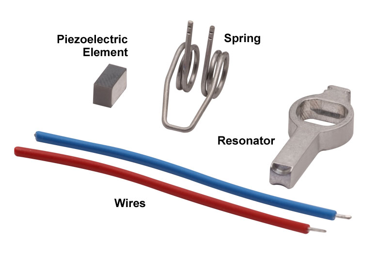
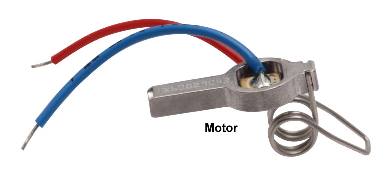
Elliptec电机的组件
Click to Enlarge
Elliptec压电谐振电机
Elliptec®压电谐振电机
Thorlabs的Elliptec®压电谐振电机(如右图所示)重量很轻,只有1.2 g,且结构紧凑:其外壳除弹簧之外的尺寸为8 mm x 4 mm x 20 mm。
电机组件
电机组件如最右图所示。压电元件压接到铝制谐振器中,其经过精心设计和精密加工,可以使顶端进行所需的椭圆运动,并良好地接合被驱动的模块。弹簧的自由端连接谐振器外壳。焊接到压电元件顶部和底部的电线可以传送电压信号,使压电元件以超声频率振动。
将电机内置于系统时,弹簧的开环被螺栓连接到一个坚固的表面,该表面相对于被驱动的物体静止,而谐振器的顶端会接触该物体。弹簧的作用是为了保持谐振器顶端与被驱动的物体稳定接触。运动方向由驱动压电元件的谐振频率决定。
椭圆运动以及与传统电机的比较
以两种谐振频率中的任一一种频率驱动电机,便可使其工作。将以超声频率振荡的电压信号施加到压电芯片时,压电芯片会以该驱动信号的频率扩展,幅度小于1微米,然后缩回原始尺寸。芯片尺寸这种快速的周期性变化可以使铝制谐振器外壳振动。当以外壳的一种谐振频率振动时,电机顶端会产生推动运动。而以另一种谐振频率振动时,则会产生拉动运动。
如视频所示,电机以谐振频率工作时,该电机顶端在空间中以椭圆路径进行推拉运动。所选的谐振频率控制周期运动的方向。电机的顶端扩展时,运动路径为椭圆路径的一半,收缩时,运动路径则为椭圆路径的另一半。电机推动所驱动的物体时,电机的顶端接触物体,同时顶端扩展;而顶端收缩时,两者不接触。当电机拉动被驱动的物体以反方向运动时,情况也是如此。电机顶端的总位移与其驱动的机械负载和施加在压电元件上的电压具有函数关系。当峰值驱动电压为5 V时,最大位移最多可以达到几微米。
该压电谐振电机与直流或电磁步进电机在许多方面都很相似,但它没有这些传统电机的一些缺点。比如,传统的电磁电机必须克服惯性延迟才能停止工作,而高动态的Elliptec电机在几微秒内就可以直接停止。由于它没有齿轮装置,因而不会有反冲现象。而且,它也没有磁铁,可以兼容对电磁干扰敏感的环境。被驱动的物体会连续而流畅地运动。由于电机的顶端必须与被驱动的物体接触以使其运动,电机具有固有摩擦制动的安全特性。与塑料表面接触时,电机几乎会无声地工作。
对于OEM应用,可以低成本批量制造这种电机,它可以由便宜的模拟电子元件驱动,且不需要微处理器和软件;但它可以与之兼容。
| Posted Comments: | |
user
(posted 2024-01-23 21:25:36.603) Hi,
I purchased a couple of rotation mounts (ELL14K and ELL18) for use with a high power femtosecond laser. I would like to have a protective cage to avoid damaging the electronic components and scattering of the laser. Do you have an example of a 3D printable design for this purpose?
Best regards. Bin Yang
(posted 2023-12-29 07:35:01.76) I am trying to use LabView to control ELL9K. Can you please send me the example VI for that. Thank you! do'neill
(posted 2024-01-04 08:46:18.0) Thank you for your enquiry. I will reach out to you directly to provide this example VI. Kirill Mitrofanov
(posted 2023-12-20 12:42:58.02) I use ELL6 in my lab and at some point I got the following issue: the motor moves only half-distance and stops there. It looks like it tries to move more, but something stops it from doing that.
Is there any solution for that? do'neill
(posted 2024-01-03 06:22:38.0) Thank you for your feedback and I am sorry to hear this. Usually this can be fixed by performing a frequency search, as operating too far from this optimum frequency can cause it to move slowly or not reach the desired location. The other thing I would suggest is to clean the rail with IPA as this can be another reason it does not reach the desired location. I will reach out to you directly to further help troubleshoot this with you. Fabian C
(posted 2023-12-15 16:19:36.24) Hi
I currently have an ELL20K/M and ELL14K/M connected through the ELLB bus, and i would like to control them both with python. I have downloaded the example EEL17_pythonnet.py, but the problem is that the program moves both of them simultaneously. How can i avoid this to have independent control? Thanks do'neill
(posted 2024-01-02 10:46:56.0) Thank you for your enquiry. This is possible with some editing of the example. As long as the devices are on different addresses, they can be controlled independently. I will reach out to you directly to help you through this. user
(posted 2023-12-07 13:29:49.057) Hi, i want to control several devices using the ELLB bus and the software ELLO. When i scan the port, it recognized one device but nothing else shows. How can i send instructions to the different devices now? (this used to work when each device was connected separately, without using the ELLB)
Thanks Andreas B
(posted 2023-11-06 11:06:29.717) Hi, We bought an Elliptec multi-positioner filter mount. It worked fine to start with but now suddenly gives "Sensor error". Any thought on how to adress this issue? do'neill
(posted 2023-11-13 04:45:37.0) Response from Daniel at Thorlabs. This is caused by the motor not reaching the correct position or not being able to sense the starting position. One of the first things you can do is frequency scan the device and gently and carefully clean the rail with IPA. I will reach out to you directly to troubleshoot this with you. Alex B
(posted 2023-09-17 23:13:49.947) Hello, I would also like to use the LabVIEW drivers. Can you send them to me too? Thanks do'neill
(posted 2023-09-19 07:21:08.0) Response from Daniel at Thorlabs. We do not have LabVIEW wrappers or drivers for the Elliptec stages but the .NET DLLs that are included with ELLO install. I will reach out to you with an example VI to get you started. Stephan Troyer
(posted 2023-08-04 12:43:47.94) In the ELLB's manual it could be useful to note that the USB RX/TX pins work as UART. Many things are quite obvious in hindsight, but when having issues (for example since the board is not responding any command when no motor is connected or when receiving garbage from a floating), that confirmation would be useful as a confirmation.
In addition, it is noteworthy, that TX/RX is reversed compared to common labelling. Usually, TX of one device gets connected to RX of the other device. On the distributor port, one has to connect the microcontroller's TX pin to the distributor board's TX pin. The naming gets slightly inconsistent since the board's TX pin is internally connected to the RX pin of the MOLEX connector.
Since it's not only the manual but also the PCB where the TX/RX labelling is printed, I would at least clearly specify the mix up it in the manual.
Best,
Stephan Troyer fguzman
(posted 2023-08-08 05:16:54.0) Thanks for your feedback. We have taken note on this and we will revise your comments on this. Ralf Wunderlich
(posted 2023-06-13 17:22:09.523) Hi,
I am using your ELL6K in a box that also houses an APD. When I connect the ELL6K to the USB port (providing power to the device), I have a significant increase in the APD's count rate? Most likely the ELL6K is using optical position feedback from an LED or something. Can you specify the wavelength?
Kind regards do'neill
(posted 2023-06-21 06:55:39.0) Response from Daniel at Thorlabs. The home sensor of the device uses a 950nm led which can leak light. This should be taken into consideration for environments that are sensitive to light sources at and around this wavelength. Kai M
(posted 2023-05-31 18:12:13.823) Hi, I'm using ELLB to control multiple ELL14. How do I set multiple devices properly in ELLO software? Could you also share Labview VI for controlling multiple devices using ELLB? Thank you! do'neill
(posted 2023-06-02 12:32:52.0) Response from Daniel at Thorlabs. I will reach out to you directly to provide these VIs and help you with your application. user
(posted 2023-04-11 18:46:31.413) Do you happen to have an example VI (LabView) written for this device available? If yes, could you please share where we can locate it? Many thanks! JReeder
(posted 2023-04-12 03:20:59.0) Thank you for your enquiry. I have reached out to you directly to provide an example LabVIEW VI for this product. user
(posted 2023-01-19 16:39:36.737) Hi, you state that the ELL series sliders should not be mounted such that the carriage moves vertically, only horizontally. Will they work if they are mounted "upside down" i.e. such that the carriage moves horizontally but the motor being above the carriage? JReeder
(posted 2023-01-20 11:52:00.0) Thank you for your enquiry. This is not something we have tested extensively, but we believe that this should work. It is worth noting though that the ELLx devices produce some fine particulates due to the friction mechanism which in this orientation can drop down onto the optics. Takahiro Deguchi
(posted 2023-01-19 14:29:55.29) Dear Thorlabs
We purchased ELL9K and installed in our single molecule microscope. Recently, we found out that ELL9 (not the interface board) emits some kind of light so that it was giving a high amount of background to our camera images. By adding short-pass 750 filter in front of camera, we could block the background signal completely. Do you know if there is any LED or a light source in IR on ELL9?
I just wanted to know if you are aware of this or if it is specified somewhere. Thank you.
Best regards
Takahiro DEGUCHI JReeder
(posted 2023-01-20 05:35:24.0) Thank you for your enquiry. All of our ELLx devices use a photo interrupter for the homing and encoder, it emits at 950 nm and the detector part is sensitive from 700 to 1200 nm. Due to this light source, applications that are very sensitive to 950 nm light should not use the ELLx devices or should take precautions to protect their application from this light. Some ELL devices may also struggle to home if they are exposed to a large amount of light in the 700-1200 nm range. user
(posted 2023-01-08 01:41:06.937) Is there any example VI (labview) written for this device? If so, where can we find it? Thank you! do'neill
(posted 2023-01-10 11:25:04.0) Response from Daniel at Thorlabs. Thank you for your inquiry. We will get in touch with you directly. Yannic Staechelin
(posted 2022-12-16 09:11:57.787) I use your ELL9 in an optical setup, where it changes its position every five seconds for some hours. In the beginning it works just fine, but after some time a "Sensor Error" occurs repeatedly. Is there anything I can do to avoid the "Sensor Error"? cwright
(posted 2022-12-16 10:24:26.0) Response from Charles at Thorlabs: Thank you for your query. These sensors are small IR LEDs paired with photodiodes. When paddles on the back of the moving world block the light from hitting the photodiode, the position of the stage is updated. Sensor errors are usually the result of ambient light/laser light getting into the photodiode, dust obscuring the photodiode, or a paddle not sufficiently blocking the light. I will reach out to you to help resolve this. Lavonne Dettmers
(posted 2022-11-08 12:27:05.457) Could you please allow the ELL9 to be generated on a RoHS compliance certificate?
Thanks,
Lavonne Dettmers cwright
(posted 2022-11-14 05:20:22.0) Response from Charles at Thorlabs: Thank you for your query. A member of technical support will look into this and reach out to you by email. Tao Ding
(posted 2022-11-04 13:26:05.6) can it be controlled via serial port?do you provide the reference code? cwright
(posted 2022-11-04 10:29:23.0) Response from Charles at Thorlabs: Thank you for your query. These devices can be controlled via serial over the USB port or by wiring directly to the relevant pins specified in the pin diagrams. THe command protocol can be found here: https://www.thorlabs.com/Software/Elliptec/Communications_Protocol/ELLx%20modules%20protocol%20manual.pdf c. Schmidt
(posted 2022-10-05 13:43:21.087) Is there a way to limit/slow down the velocity and/or acceleration of ELL9? cwright
(posted 2022-10-06 05:33:53.0) Response from Charles at Thorlabs: Thank you for your query. Unfortunately this is not possible with the filter sliders. The elliptec mounts are designed for quick positioning but not for control over the velocity parameters. Zihao Pang
(posted 2022-05-12 22:13:36.01) Hi Thorlabs,
we've recently purchased the ELL14K Bundle. We are wondering if it is possible to make this rotator have continuous rotation for many full turns? For example, can this rotator keep jogging?
Many thanks and best regards,
Zihao cwright
(posted 2022-05-13 04:33:45.0) Response from Charles at Thorlabs: Thank you for contacting us. The ELL14 is currently limited to 720 degrees of rotation by jogging. It is also possible to set non-stop continuous rotation at a slower speed and this is described in the communications protocol (https://www.thorlabs.com/Software/Elliptec/Communications_Protocol/ELLx%20modules%20protocol%20manual.pdf). I will reach out to discuss this with you. David Roesel
(posted 2022-01-31 06:43:39.32) In case anyone is interested, we are writing a Python library for easy control of Elliptec devices. Feel free to reach out if you have any questions.
https://github.com/roesel/elliptec cwright
(posted 2022-02-01 06:08:14.0) Response from Charles at Thorlabs: Thank you for contacting us! We think it's great to see the community engaging with our products and creating such libraries, although of course Thorlabs cannot take responsibility for the content and maintenance such community provided libraries. We are sure there is potential to benefit a number of people.research teams and will reach out to you to discuss your work. user
(posted 2022-01-18 18:07:32.8) What is the Maximum Total Load in the horizontal movement mode? cwright
(posted 2022-01-20 05:25:06.0) Response from Charles at Thorlabs: Thank you for your query. We would still suggest a maximum load of 150g in this configuration. Friedemann Heinz
(posted 2021-12-09 11:47:10.013) Short comment:
It would be nice if the device would be "thinner". This could be realised by offering a slider with deeper threads such that a filter may be directly mounted in the slider without the use of additional lense tubes. There is actually a quite large gap betwenn slider and red electronic board.
Best,
Friedemann Heinz cwright
(posted 2021-12-09 08:04:12.0) Response from Charles at Thorlabs: Thank you for your feedback! I can see how this would be advantageous and will post your feedback on our internal forums for our engineers to contemplate. user
(posted 2021-11-08 09:03:48.587) Is it possible to perform small movements within one sample, i.e. not a full sample jump? cwright
(posted 2021-11-08 11:11:30.0) Response from Charles at Thorlabs: Thank you for your query. Unfortunately this is not possible. I would suggest using an ELL17/M or ELL20/M and positioning an optic mount such as LMR1/M on top. user
(posted 2021-10-22 07:48:52.753) When using ELL6 or ELL9 products (and other USB stages), is it possible to use a USB hub (mains-powered) ?
ELL9 warns against having the component plugged in USB when a computer isn't fully on. What of a USB hub ? Can it be plugged as long as the hub is powered ? Should the cable be disconnected every time beofre we power off the computer or hub ? Under which conditions can we let an ELL stage connected ? cwright
(posted 2021-11-01 11:42:33.0) Response from Charles at Thorlabs: Thank you for your query.
This was an issue with old versions of the USB remote interface board. Version 2 onwards should not have this issue. The issue is backfeeding of current to the USB hub. The way the USB has been implemented within the computer's USB HUB will determine whether or not it is suitable and our engineers found that even within the same laptop you could have some USB ports which are OK and will not be affected and others which are not OK and could have this issue. If using the old board then the only way to be sure is to either power the PC first or to desolder the transistor (labelled Q1 on the old boards). You cannot fix this with an external HUB. user
(posted 2021-08-20 18:05:54.71) Is there any SDK or module to develop 3rd party software with python cwright
(posted 2021-08-27 10:11:14.0) Response from Charles at Thorlabs: Thank you for your query. With Python we would recommend using the serial command protocol and I have reached out to you with an example which should get you started. The protocol is available here: https://www.thorlabs.de/Software/Elliptec/Communications_Protocol/ELLx%20modules%20protocol%20manual.pdf user
(posted 2021-08-20 18:04:38.94) Is there any SDK or module to develop 3rd party software with python user
(posted 2021-08-17 04:28:11.31) I think it should be stated more prominently (maybe on the main product page and not only in footnote (c) on the specs page) that the ELL9 can only be operated horizontally. When mounted on, e.g., a motorized rotation mount (which might be something a lot of customers think of as a possible application scenario), the ELL9 only moves correctly when aligned horizontally. In vertical orientation (rotation stage turned by 90 degrees), the motors are to weak to move even the weight of the slider alone, i.e., without any optics attached. Even though this might be obvious, it might still be a good idea to put a comment on the webpage.
In our case, we found a quick workaround, always turning the rotation mount before changing the ELL9 position, so that the slider motion always occurs in the horizontal direction. But other customers may want to use the slider at arbitrary rotation angles, which won't work out.
Apart from that, these are awesome devices. cwright
(posted 2021-08-18 05:29:28.0) Response from Charles at Thorlabs: Thank you for your feedback. We will consider adding a clarifying note to the web presentation. The behaviour in this orientation is more due to the nature of the motor than its strength. The motor's tip follows an elliptical path when active and in order to advance the moving world it must leave contact with this moving world for a short time each repetition. When used with the slider orientated vertically the effect of gravity would oppose the intended motion of the slider and cause slipping. This motion can be seen in more detail in the video on the following page:
https://www.thorlabs.com/newgrouppage9.cfm?objectgroup_id=9464&tabname=The%20Elliptec%20Motor joe M
(posted 2021-07-26 13:17:28.53) Hi,
I am hoping to control the ELL9K using labview (2017 32-bit). My computer is 64 bit and everytime I try to download the 32bit elliptec software so I can access the DLL I get an error saying I need an x86 processor. Can someone provide me with the DLL file? Also, is it possible to get example code for labview control?
Thanks cwright
(posted 2021-07-27 10:47:41.0) Response from Charles at Thorlabs: Thank you for your query. If you have 32 bit LabVIEW on 64 bit windows then all your DLLs will need to be of 32 for 64 bit (WOW64) type. The Elliptec DLLs are only available as 64 bit or 32 bit. In this case you would need to have a 64 bit installation of LabVIEW or communicate with the Elliptec devices using serial commands. Technical support will reach out to you to discuss this. cwright
(posted 2021-07-27 10:47:41.0) Response from Charles at Thorlabs: Thank you for your query. If you have 32 bit LabVIEW on 64 bit windows then all your DLLs will need to be of 32 for 64 bit (WOW64) type. The Elliptec DLLs are only available as 64 bit or 32 bit. In this case you would need to have a 64 bit installation of LabVIEW or communicate with the Elliptec devices using serial commands. Technical support will reach out to you to discuss this. Jiri Junek
(posted 2021-07-23 04:56:18.707) Dear Thorlabs,
I want to use ELL14K and ELL17K/M in one optical setup. Am I need a Bus Distributor ELLB or can I control both devices separately? I plan to control the whole setup in Matlab.
Thank You for the information! cwright
(posted 2021-07-23 06:36:12.0) Response from Charles at Thorlabs: Thank you for your query. You can control both separately. The ELLB is most suitable when you want to have many devices on a single USB port but you can use these two on separate USB ports and they will appear to your computer as two COM ports. I have reached out to you to discuss your application in more detail.
If using Matlab we would recommend you send serial commands according to our communication protocol: https://www.thorlabs.de/Software/Elliptec/Communications_Protocol/ELLx%20modules%20protocol%20manual.pdf Luis Mollinedo
(posted 2021-05-11 06:30:42.76) Dear sir/madam,
We're interested in your Multi-Position Sliders with Resonant Piezoelectric Motors, specifically in your ELL9K bundle.
As we're planning to control the slider from an computer, running GNU/Linux OS (Ubuntu 20.04), is your software compatible with this OS? If not, is possible for us to develop our own driver (e.g. via serial communication).
Thanks in advance,
Luis Mollinedo
Robotics Lead
Overture Life
https://overture.life jcater
(posted 2021-05-12 09:35:49.0) Response from Jack at Thorlabs: Thank you for your inquiry. Unfortunately our ELLO software is only compatible with Windows OS. You can communicate with the ELL9 through serial commands using the interface board or, for example, an Arduino or Raspberry Pi board, or by wiring the RX and TX connector pins to your own board. The command protocol can be found here https://www.thorlabs.com/Software/Elliptec/Communications_Protocol/ELLx%20modules%20protocol%20manual.pdf. Amit Meller
(posted 2021-04-26 07:30:30.727) Hi,
It would be great if the ELL6K (as well as the other units in this line) will be ready to controlled using LabView, in a similar way to many of other Thorlabs products.
This unit is integrated in optomechanical prototypes or setups containing many elements and imaging devices and while the stand alone software is nice, it is not practical for full system integration.
Thank you
Amit Meller cwright
(posted 2021-04-26 11:23:16.0) Response from Charles at Thorlabs: Thank you for your feedback. It is possible to use Elliptec devices in LabVIEW either by using the serial commands over VISA or by using the .NET DLL, detailed in the DLL which is downloaded with our software. By default it is found in the following loation: C:\Program Files\Thorlabs\Elliptec. The DLL is 64-bit, so your installation of LabVIEW would also need to be in order to use the DLL. For serial using VISA this is not important.
As you have opted not to be contacted by us please contact technical support if you have questions regarding this. jiang peng
(posted 2021-04-20 12:38:38.79) Some bugs were mainly found. The resonant motor will produce auto-fluorescence after plugging in the USB, about 100kcounts/s, which is detected by APD (Single Photon Counter), which is very fatal for microscopic fluorescence testing and will cover up when scanning imaging. For weak light signals, a single nanoparticle is usually only 15k-40kcounts/s. James Grieve
(posted 2021-03-11 20:38:22.797) When using the ELLB to control multiple stages over serial, is there any way to enumerate connected devices? The protocol manual is silent on this, mentioning only that the default address is '0'. cwright
(posted 2021-03-11 09:51:46.0) Response from Charles at Thorlabs: Thank you for your query. When using multiple stages on the same COM port you will have to change their addresses by attaching one stage at a time. This can be done using the ELLO software through the "Change Address" option at the top of the program window and then saving the change by clicking Save User Data in the "Settings" panel.
Alternatively you can send the commands 0ca1, to change the address of a stage from 0 to 1, followed by the user save command to address 1, i.e. 1us. These are described in more detail in the command protocol document: https://www.thorlabs.com/Software/Elliptec/Communications_Protocol/ELLx%20modules%20protocol%20manual.pdf user
(posted 2021-03-04 08:40:58.017) Hi, can I get example for LabVIEW (2018 32 bits) ?? Thanks cwright
(posted 2021-03-09 08:11:03.0) Response from Charles at Thorlabs: Hello and thank you for your query. We will reach out to you about an example you can use. user
(posted 2021-02-04 14:25:47.1) Hi, my ELL9 slider started mooving with difficulty, as its rail would need some oil or fat. What kind of oil/fat should I use? Thanks cwright
(posted 2021-02-05 08:51:32.0) Response from Charles at Thorlabs: Hello and thank you for your query. By far the most common cause of movement issues are settings such as incorrect motor frequencies and you could try a frequency search. If there is a lot of dust/dirt which has entered the linear rail then you could try cleaning it with Ultrasol. Your local technical support team has already reached out to you. Naaman Amer
(posted 2019-07-10 16:32:28.25) Hi
Can I use the device in Vacuum environment?
Can I control it via labview?
Thanks AManickavasagam
(posted 2019-07-19 05:04:02.0) Response from Arunthathi at Thorlabs: Thanks for your query. Unfortunately, except for the motor itself the elliptic range is not vacuum compatible. This could be controlled with Labview (the .dll files would be in the installation folder). Peter Domenicali
(posted 2019-05-22 00:56:54.707) Can the ELL6 be used long-term upside down? That is, with the bulk of its PC board pointing upwards, opposite to how it is shown in all your images? I should think one concern would be whether any wear particles will slough off of the friction interface, where the "inch worm" drive oscillates. If so these particles might drop down onto the optic being moved. But any other reason this wouldn't work? AManickavasagam
(posted 2019-05-22 11:37:11.0) Response from Arunthathi at Thorlabs: Thanks for your query. The ELL6 should be perfectly fine to work in the flipped orientation you require. user
(posted 2019-04-03 04:07:51.447) Hi Thorlabs service Team,
Nice little product. I am using the serial commands in python (pyserial) to access the four-position slider.
The connection is always successful and "0in" always returns the right output. Occasionally however, a "0ma00000000" is unsuccessful and returns a "signal error" - "0GS0A". Once it occurs, I can't move the stage anymore, even when I disconnect with python and connect with ELLO. (0ma attempts always return 0GS0A) Unplugging the stage resolves this issue but do you have any advice on how I could prevent this from happening?
Note: This never happened so far with the ELLO_DLL in python but I would prefer serial commands to keep the script more versatile. user
(posted 2019-04-05 07:13:29.0) Response from Arunthathi at Thorlabs: Thanks for your query. The encoder error (0x0A) returned is a discrepancy between number of count position and requested position. It is generally a mechanical issue: vibration, moving load, stage moved or stopped by hand.
It is recommended to use HOME instead of “ma” to go to the 0 position.
Home resumes the unit from error (caused by vibration) as it resets the encoder to a known absolute 0 position.
If the issue still persists please contact your local tech support team directly for further assistance. Julien PROUST
(posted 2019-03-26 11:28:40.167) I measured the stability:
Positioning Repeatability +/-0.26 mm in normal condition (vertical)
After around 30 actuations, a shift of 0.1 mm appears user
(posted 2019-03-27 11:07:04.0) Response from Arunthathi at Thorlabs: Thanks for your feedback. To look into this further we will need to analyse your test setup and methods. I have contacted you directly for further details. user
(posted 2019-02-12 15:45:57.423) I second: Would be awesome to have micromanager support! rmiron
(posted 2019-02-14 05:41:42.0) Response from Radu at Thorlabs: Thank you for sharing your thoughts with us. I will relay your feedback internally. keisuke.yoshioka
(posted 2018-11-04 21:21:15.983) ELL9Kで穴位置を細かく動かしたいのですが、maコマンドが使えないようでした。
maコマンドを使用できるように、仕様を変更して欲しいです。 rmiron
(posted 2018-11-06 04:33:55.0) Response from Radu and Fumi at Thorlabs: この度はお問合せいただきありがとうございました。ご要望をファームウエア開発チームに伝え確認いたしました。"ma"コマンドや"mr"コマンドはELL9で使用することは自体は可能です。ただし、決められた4つのスライダーポジションに移動できるだけであり、精密な移動はできません。これは、他のElliptec製ステージと異なり、ELL9がエンコーダを搭載していないためであり、大変恐れ入りますがファームウエアの改造のみでは実現ができません。ただ、所定の時間に対してスムースに移動するようコマンドを送ることは可能です。そのようなコマンドに対するご質問や"ma"コマンドに対する応答についてのご質問がございましたら、弊社の日本オフィスsales@thorlabs.jpにご連絡くださいませ。
Translation:
Feedback: I want to finely move the hole positions with ELL9K, but it seems that the 'ma' (move absolute) command can not be used. I'd like for the stage to change such that we can use the 'ma' command.
Response: Thank you for your feedback. I have relayed it to the developers of Elliptec's firmware who will take it into account when planning for future releases. The 'ma' and 'mr' commands can be used on ELL9, but only to switch between the 4 slider positions. Unfortunately, we can't modify this stage's firmware in order to allow these commands to be used for fine translations. This is because ELL9, as opposed to the other Elliptec stages, lacks an encoder. With that being said, we could add a similar command that would allow one to translate the stage for a given period of time. If your stage is not responding to the 'ma' or 'mr' commands, please contact our Japanese office at sales@thorlabs.jp. lvjing
(posted 2018-04-19 14:52:34.907) Usb plugged in the computer can not identify the device bhallewell
(posted 2018-04-19 12:21:32.0) Response from Ben at Thorlabs: Thank you for your email. I'll contact you to troubleshoot the problem. massimo
(posted 2018-03-29 14:55:49.94) Is it possible to turn off the LEDs in the interface board?
I'm using this slider to move ND filters and my optical setup is enclosed in a light tight box, because I need to perform measurement at very low light. The flat cable between the interface board and the slider is too short so I have to keep the interface board inside the light controlled box, but the light intensity of the LED on the board is not at all negligible. At the moment I'm covering the LED with black tape, but it's definitely not enough and not very nice.
I couldn't find anything about it in the documentation. It'd be great if didn't have to replace the flat cable with a longer one.
Thanks bhallewell
(posted 2018-04-05 07:19:20.0) Response from Ben at Thorlabs: Thank you for your feedback. There isn't a programming solution to turn off the LED however you should have access to remove the LED or alternatively short the LED with a wire. user
(posted 2018-03-27 17:29:38.03) It would be awesome if this had drivers for micro manager. rmiron
(posted 2018-04-11 05:16:53.0) Response from Radu at Thorlabs: Thank you for your feedback. I have relayed it to our developers. I will contact you directly regarding our future plans on this front. Roger.John
(posted 2018-02-15 22:01:57.177) Can one mount a ME1-P01 in one position of the ELL6, as a flip mirror alternative? Thanks! bhallewell
(posted 2018-02-23 10:55:22.0) Response from Ben at Thorlabs: You will be able to mount this optic through use of our SM1L03 SM1 Lens tube, which includes an SM1RR retaining ring to secure the optic in the lens tube. The optic seated in the lens tube can then be threaded into the ELL6 mount. The total load that the slider can actuate is 0.150 kg. user
(posted 2017-10-25 15:33:18.65) Could the ELL6 be used in a medium vacuum (>10^-2mbar) environment? Thank you very much. bwood
(posted 2017-10-30 05:06:50.0) Response from Ben at Thorlabs: Thank you for your feedback. While in principle the Elliptec motor technology will work in a vacuum, the stock ELL6 slider contains several components which will outgas, so it may not be suitable for your application. If you would like to pursue this further, I would suggest contacting your local tech support office, to discuss your application in more detail. nhuffman
(posted 2017-07-25 10:20:39.697) Are there any 32bit libraries for the Eliptec software available for 64bit Windows like are available for the APT and Kinesis software? I need to interface with 32bit MATLAB on a 64bit machine. bwood
(posted 2017-07-26 09:27:16.0) Response from Ben at Thorlabs: Thank you for your question. Unlike Kinesis compatible devices, our Elliptec devices are controlled solely through serial commands (directly or through our Elliptec System Software). You should be able to configure MatLab to communicate through these serial commands however. You can find the serial communications protocol on the Elliptec software webpage. bjorn.fjelddahl
(posted 2016-11-29 08:32:55.62) Hi
The ELL6 is made for 2 filters
Is it possible to add two more filters to a total of 4?
Best regards,
Björn bhallewell
(posted 2016-12-01 07:23:58.0) Response from Ben at Thorlabs: Thank you for your enquiry. This would likely fall within our capabilities for customisation. I will contact you to discuss this opportunity further. user
(posted 2016-11-04 16:04:37.99) Do the top two threaded hole have clearance from the sliding portion to attach 30 cage posts on each side? i.e. can you stack multiples of these? bhallewell
(posted 2016-11-09 09:39:00.0) Response from Ben at Thorlabs: Thank you for your question here. Checking our web models, there is not enough clearance for an ER 30mm cage rod system to mate with the PCB from both sides, this is a 4-40 hole which can only be accessed from the rear side. This is one of our off-the-shelf solutions & is limited in customisation however for OEM opportunities we may be able to go beyond this. I will contact you directly to start a discussion. |

 放大
放大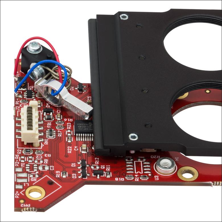
Click to Enlarge
红线和蓝线可以给电机送电,其铝制顶端与滑动板的边缘相接触。工作时,电机顶端以超声速度做微观的循环运动。人眼无法看到它的运动。

- 非常适合OEM评估测试
- 便于集成到装置中
- 通过手动和/或计算机控制操作
这些滑动式多孔安装座套件是完整的套件,包含滑动式安装座(也可以单独出售)以及其他列在下表中的元件。ELL6只带一个电机,通过USB可以同时实现控制和供电。由于ELL12和ELL9有两个电机,因此需要的功率较大,其套件附带5 V电源。
这些套件便于将滑动式安装座集成到实验室装置和其他实验应用之中。它们还提供了一种便利的方法,评估该技术与OEM应用的集成。
| Kit Components | |||
|---|---|---|---|
| Item # | Slider | Accessories | Power Supply |
| ELL12K | ELL12 Slider with Six SM05-Threaded Ports | Interface Board, USB Cable, Ribbon Cable (8-Conductor, 28 AWG) | 5 V Power Supply with Region-Specific Plug |
| ELL6K | ELL6 Slider with Two SM1-Threaded Ports | - | |
| ELL9K | ELL9 Slider with Four SM1-Threaded Ports | 5 V Power Supply with Region-Specific Plug | |

 放大
放大| Item # | # of Ports | Port Thread |
|---|---|---|
| ELL12 | 6 | SM05 (0.535"-40) |
| ELL6 | 2 | SM1 (1.035"-40) |
| ELL9 | 4 |
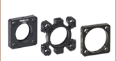
- 滑动式多孔安装座的独立版本,带SM05或SM1螺纹端口
- 直接连接到现有接口板或直接通过多点TTL RS-232接口控制滑动板
- 适合不需要接口板和电缆的应用
- 可用于扩展已有的Elliptec®装置组合
这些滑动式多孔安装座可以单独出售。它们适用于需要连接多个Elliptec®谐振电机产品的应用,或不需要套件里其他组件的应用。滑动板上的每个位置具有SM05或SM1螺纹孔,螺纹深度3.5 mm。PCB中包含四个4-40的螺孔,兼容Thorlabs的30 mm笼式系统,可以用来安装滑动安装座。
两种安装座的PCB板包含一个公头8引脚的Picoflex®接头(插头)。这些单独的安装座发货时带有母头8引脚的Picoflex®接头(插座),可以匹配板上的接头(插头)。详情请看引脚图标签。

 放大
放大| Specifications | ||
|---|---|---|
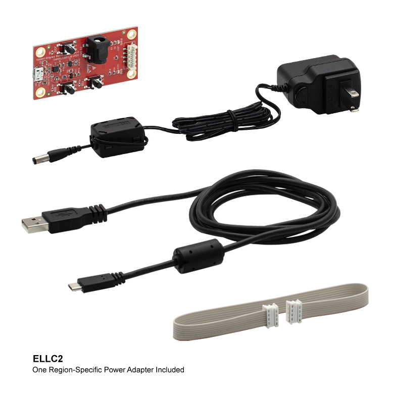
| Item # | ELLC2 | |
| DC Voltage Input to Controller | 4.5 to 5.5 V | |
| Typical Current Consumption Per Module | Movement | 800 mA |
| Standby | 50 mA | |
| Operating Temperature Range | 15 to 40 °C | |
| Ribbon Cable Length (1 Included) | 250 mm (9.84") | |
| Maximum Supported Ribbon Cable Length | 500 mm (19.68") | |
| Dimensions (Interface Only) | 66.0 mm x 32.0 mm x 12.5 mm (2.60" x 1.26" x 0.49") | |
| Weight (Interface Only) | 10.8 g (0.022 lbs) | |
- 通过添加以下组件将单个ELL设备升级为套件:
- 手持式控制器
- USB Micro B电缆
- Picoflex®1电缆
- 5 V电源,带符合当地使用的适配器(US、UK、AU或EU)

Click for Details
ELLC2电源中符合当地使用的适配器类型
Thorlabs的ELL配件升级包包含可将任何单个ELL滑动式安装座、位移台或支架升级为ELL套件2所需的所有配件。随附的手持式控制器具有三个按钮,用于控制所连ELL位移台的位置,控制器的USB端口可通过随附的USB Micro B电缆直接连接到PC。升级包中还附带一根0.25 m Picoflex®电缆,其具有8个负载电路,可将手持式控制器连接到ELL设备,升级包中的5 V 电源带有符合当地使用的适配器(US、UK、AU或EU)。
- 注意:Picoflex®是Molex Incorporated的注册商标。
- 如需用于ELL17(/M)、ELL18(/M)和ELL20(/M)的安装支架,请联系技术支持techsupport-cn@thorlabs.com。

 放大
放大| Specifications | ||
|---|---|---|
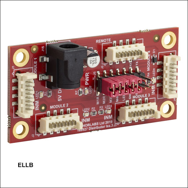
| Item # | ELLB | |
| Voltage Rating | 4.5 to 5.5 V | |
| Typical Current Consumption Per Module | Movement | 800 mA |
| Standby | 50 mA | |
| Maximum Board Current | 4.0 A | |
| Operating Temperature Range | 15 to 40 °C | |
| Ribbon Cable Length (4 Included) | 250 mm | |
| Maximum Supported Ribbon Cable Length | 500 mm | |
| Dimensions | 65.0 mm x 32.0 mm x 12.5 mm (2.56" x 1.26" x 0.49") | |
| Weight | 11 g (0.02 lbs) | |
Click to Enlarge
一个总线分配器可控制多达四个Elliptec装置。可以使用上面出售的套件中包含的接口板将总线连接到PC。请注意,之后由Elliptec软件控制总线,且禁用了接口板上的按钮。
- 通过一根总线控制和供电多达四台Elliptec®装置
- 菊花链总线板可控制多达16个Elliptec装置
- 使用Elliptec系统软件进行远程控制(请查看上方软件标签)
- 使用Elliptec套件包含的USB接口板连接到PC
- 包含五根跳线和四根8线28 AWG带状电缆
- 与Raspberry Pi®和Arduino®板兼容
ELLB总线分配器最多可连接四个Elliptec®装置。不论有无上述套件包含的接口板,都可以控制连接的装置。使用接口板时,每台连接装置可通过运行Elliptec软件包的PC进行远程控制。接口板连接到标有REMOTE的总线输入口;连接后,接口板的按钮将被禁用。要在不使用接口板的情况下进行控制,请查看引脚图标签进行自定义连接。
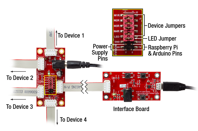
可以通过菊花链方式连接多个ELLB总线分配器,以控制最多16个Elliptec装置并为其供电;只需将四个MODULE输出之一连接到第二个板的REMOTE输入。指示灯LED可显示哪个装置处于活动状态。通信协议手册介绍了如何使用软件分别寻址每个连接的装置。可在软件标签中找到下载软件和包含文档的链接。
此总线包括一个Ø6.3 mm电源接头,支持5 V电源,最大电流4 A。随着连接装置增多,同时控制这些装置将需要电源提供更多电流;这将导致总线电压降低。请查看规格标签了解每个Ellitpec装置消耗的电流量。上述ELL9和ELL12套件包含5 V、1 A电源。根据所连接Elliptec装置的电流消耗,这些电源可提供足够的电流为两个装置同时供电。
如右图所示,包含的十四个控制引脚具有附加功能。四对引脚分别通过跳线短接,当安装完成,此跳线使Elliptec软件能够接收来自已连接Elliptec装置的反馈。标有LED的一对引脚通过跳线短接,跳线拆下后会禁用LED指示灯。5V和GND允许使用用户提供的可选5 V、2 A电源来代替与Ø6.3 mm电源接头相连电源。RX和TX引脚可分别通过Raspberry Pi®或Arduino®板(而不是Elliptec接口板)以控制总线。
使用每个角上的Ø3.5 mm通孔安装电路板。包含四根8线、28 AWG带状电缆。
| Compatible Elliptec Devices | |||||
|---|---|---|---|---|---|
| | | | | |
| Multi-Position Sliders | 28 mm Linear Stage | 60 mm Linear Stage | Rotation Stage | Rotation Mount | Motorized Iris |

 放大
放大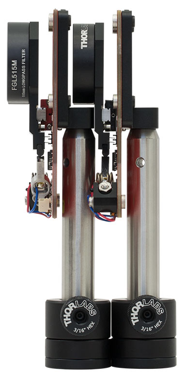
Click to Enlarge
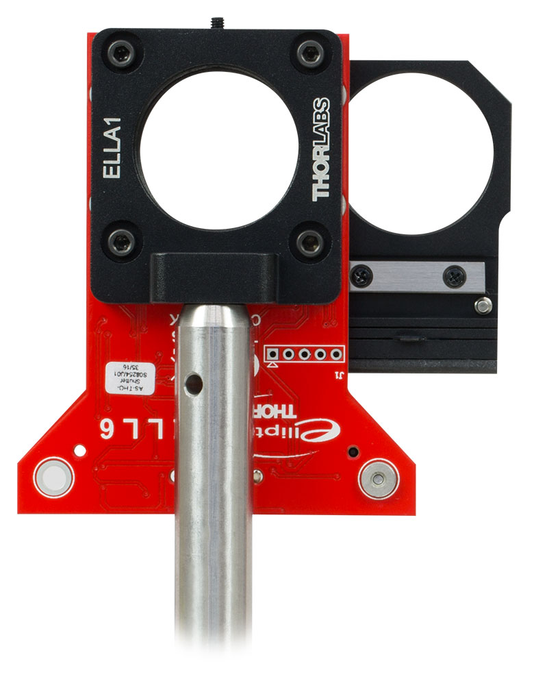
ELLA1通过四个4-40的螺孔安装在安装座PCB的背面,其也兼容30 mm笼式系统组件。
- 直接安装在滑动式安装座PCB上
- 正面的间隔槽兼容PCB背面的突出部分
- 四个用于4-40螺丝的沉头孔
- 一个用于8-32(M4)螺丝的沉头孔
- SM1(Ø1.035-40)内螺纹
ELLA1接杆安装转接件通过附带的四个4-40螺丝可以固定在滑动式多孔安装座PCB的背面。然后,利用转接件底部的沉头孔和一个8-32(M4)螺丝(不附带)就可以将安装座安装到Ø1/2英寸接杆。通过SM1(1.035"-40)内螺纹孔可以将透镜套管或其他元件安装到转接件。利用四个沉头孔通过Ø6 mm笼杆也可以将ELLA1连接到30 mm笼式系统。
该转接件的总尺寸为40.0 mm x 44.0 mm x 14.0 mm,能够将接杆紧贴着安装座PCB的背面安装。特别推荐将该转接件用于需要前后紧密放置多个滑动式安装座的应用。转接件的几何形状允许将安装在滑动式安装座上的光学元件定位在将滑动式安装座直接安装在前面的接杆上方。这些转接件也可以进行单组件安装,适合常见的应用。