 Products Home
Optics Multipacks
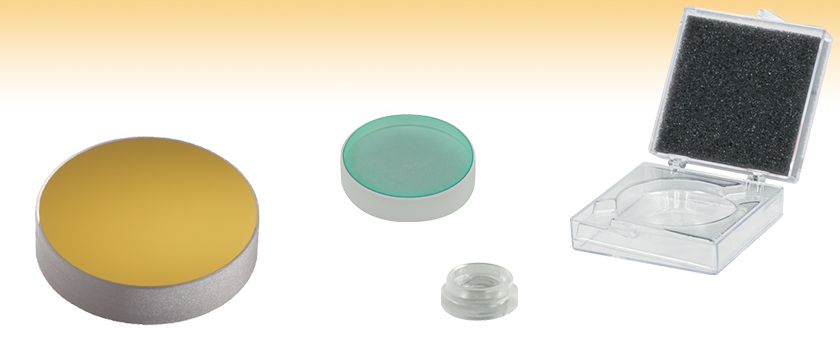
- Metallic and Dielectric Mirrors in Packs of 10
- Plastic Asphere Lenses in Packs of 25, 50, or 100
- Optics Storage Boxes in Packs of 5 or 10
- Simplify Ordering and Reduce Packaging Waste
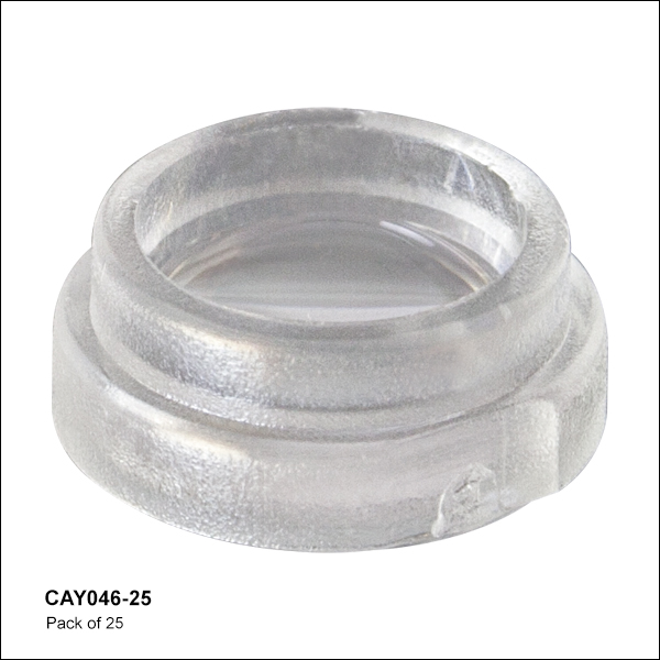
CAY046-10
Pack of 25 Plastic Asphere Lenses
Ø7.44 mm, f=4.6 mm, 0.40 NA
BB1-E03-10
Pack of 10 Ø1" 750-1100 nm
Dielectric Mirrors
PF20-03-M01-10
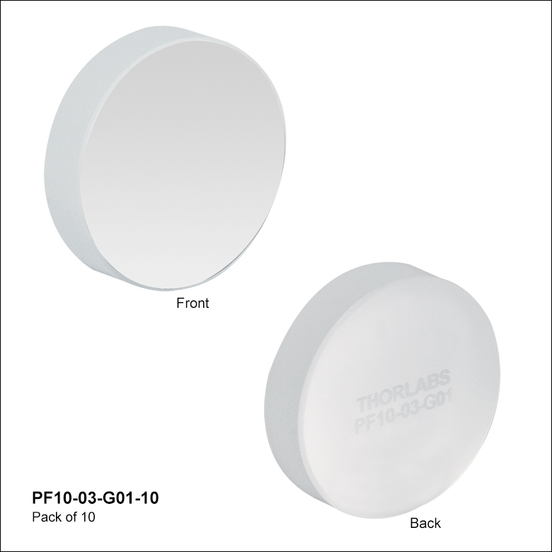
Pack of 10 Ø2" Protected
Gold Mirrors
BX02
Pack of 5 Ø2" Optic Storage Box


Please Wait

 Zoom
Zoom- Seven Metallic Coatings Available
- UV-Enhanced Aluminum: Ravg > 90% for 250 - 450 nm
- Protected Aluminum: Ravg > 90% for 450 nm - 2 µm, Ravg > 95% for 2 µm - 20 µm
- Protected Silver: Ravg > 97.5% for 450 nm - 2 µm, Ravg > 96% for 2 µm - 20 µm
- Ultrafast-Enhanced Silver: Rs > 99.0% and Rp > 98.5% for 750 - 1000 nm
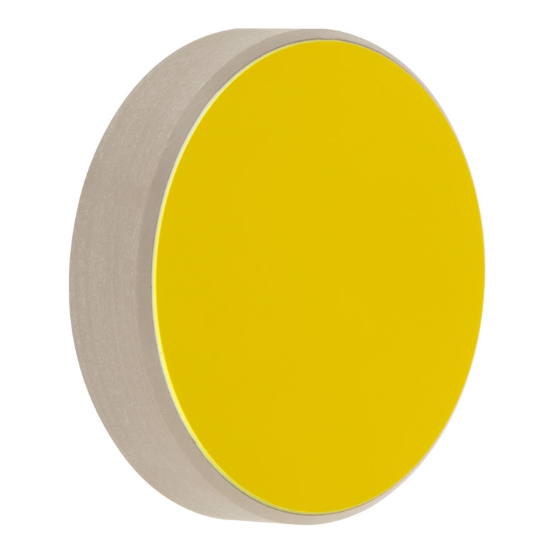
- Protected Gold: Ravg > 96% from 800 nm - 20 μm
- Unprotected Gold: Ravg > 97% from 800 nm to 20 µm
- MIR-Enhanced Gold: Ravg > 98% from 2 μm - 20 μm
- λ/10 Surface Flatness
- Ø1/2" (Ø12.7 mm), Ø1" (Ø25.4 mm), and Ø2" (Ø50.8 mm) Mirrors Available
- Each Pack Includes 10 Mirrors
High-quality, metal-coated optical mirrors are available for use with light throughout the UV, visible, and IR spectral regions. Each metallic coating has a high reflectance of greater than 90% over its specified region. As seen in the reflectance graphs in each of the above tabs, these metallic mirrors are relatively insensitive to angle of incidence except for the ultrafast-enhanced silver mirror, which is specified for use at a 45° AOI. For complete details and specifications on the various metallic coatings offered in packs, please see the tabs above.
Individually sold metallic mirrors, including economy mirrors, square mirrors, Zerodur® mirrors with low thermal expansion, and mirrors for use with CO2 lasers, can be found through our plano metallic mirrors guide.
UV-Enhanced Aluminum
Our UV-Enhanced Aluminum Mirrors are a cost effective solution for UV applications. Because bare aluminum is extremely delicate and susceptible to damage, a protective overcoat is layered over the aluminum to prolong the life of the mirror. Our UV-enhanced coating is made by using an overcoat of MgF2, which offers >90% reflectance from 250 to 450 nm. Our Ø1" UV-enhanced aluminum mirrors are available here in packs of 10. Please see the Aluminum tab for full specifications and reflectance curves.
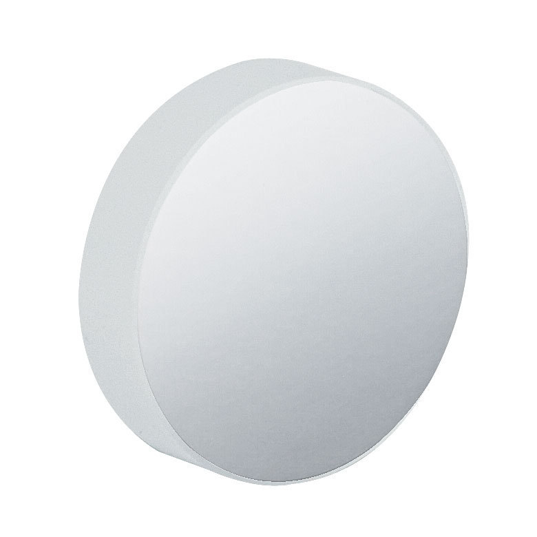
Protected Aluminum
Protected Aluminum Mirrors are a good option for many general broadband applications. An SiO2 coating is used to protect the delicate aluminum coating, making it suitable for laboratory and industrial use. The protected aluminum coating has a smaller chance of tarnishing than protected silver in a high humidity environment, and gives a reflectance that most closely matches the reflectance of a bare aluminum coating. These mirrors have an average reflectance greater than 90% from 450 nm to 2 µm and greater than 95% over the 2 to 20 µm spectral range. These protected aluminum mirror ten packs are available in Ø1/2" and Ø1" optic diameters. Please see the Aluminum tab for full specifications and reflectance curves.
Protected Silver
Protected Silver Mirrors provide the highest reflectance of any metallic mirror in the visible-NIR range, and also offers high reflectance well into the IR range. Each protected silver mirror has a durable SiO2 overcoat, which helps prevent the silver from tarnishing. High-humidity environments should be avoided when using these mirrors. Protected silver offers an average reflectance of >97.5% from 450 nm to 2 µm, and >96% from 2 µm - 20 µm. These protected silver mirror ten packs are available in Ø1/2", Ø1", and Ø2" optic diameters. Please see the Silver tab for full specifications and reflectance curves.
Ultrafast-Enhanced Silver
Ultrafast-Enhanced Silver Mirrors are designed for applications in the fundamental wavelength range of femtosecond Ti:Sapphire lasers. These mirrors are manufactured with a dielectric overcoat that provides >98.5% absolute reflectance over the 750 - 1000 nm wavelength range, and they largely retain the low group delay dispersion (GDD) intrinsic to metallic coatings. Our Ø1" ultrafast-enhanced silver mirrors are available here in packs of 10. Please see the Silver tab for full specifications and reflectance curves.
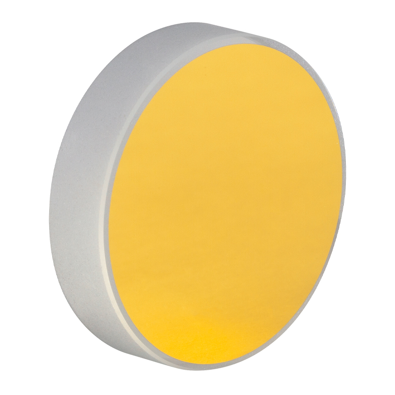
Protected Gold
Protected Gold Mirrors offer the flattest IR reflectance of all the metallic mirrors offered. Each protected gold mirror features a protective dielectric overcoat which helps to protect the fragile gold layer from damage and makes cleaning easier. Protected gold provides >96% average reflectance from 800 nm to 20 µm. These protected gold mirror ten packs are available in Ø1/2", Ø1", and Ø2" optic diameters. Please see the Gold tab for full specifications and reflectance curves.
Unprotected Gold
Unprotected Gold Mirrors are ideal for applications where the polarization state needs to be strictly maintained or the dispersion caused by the dielectric overcoat of protected gold mirrors is undesirable. With a >97% average reflectance from 800 nm to 20 μm, unprotected gold provides a higher average reflectance than protected gold, but it is more delicate and easily damaged by fingerprints, aerosols, or the slightest contact with any abrasive material. These unprotected gold mirror ten packs are available in Ø1/2", Ø1", and Ø2" optic diameters. Please see the Gold tab for full specifications and reflectance curves.
MIR-Enhanced Gold
Mid-Infrared (MIR) Enhanced Gold Mirrors provide >98% average reflectance from 2 μm - 20 μm without suffering losses found with protected gold mirrors. The overcoat on these mirrors allows them to perform better than our unprotected gold mirrors in the MIR, while offering resistance to physical damages. These MIR-enhanced gold mirror ten packs are available in Ø1/2", Ø1", and Ø2" optic diameters. Please see the Gold tab for full specifications and reflectance curves.
UV-Enhanced Aluminum
Click to Enlarge
PF10-03-F01 UV-Enhanced Aluminum Mirror
| Item # | PF10-03-F01-10 |
|---|---|
| Diameter | 1" (25.4 mm) |
| Diameter Tolerance | +0.0 mm / -0.1 mm |
| Thickness | 6.0 mm (0.24") |
| Thickness Tolerance | ±0.2 mm |
| Reflectance | Ravg >90% from 250 to 450 nm |
| Reflectance Plot (Click for Plot) |  |
| Substrate | Fused Silica |
| Flatness | λ/10 @ 633 nm |
| Parallelism | <3 arcmin |
| Clear Aperture | >90% of Diameter |
| Damage Threshold (Pulsed) | 0.25 J/cm2 at 266 nm, 10 ns, 10 Hz, Ø0.150 mm 0.3 J/cm2 at 355 nm, 10 ns, 10 Hz, Ø0.381 mm |
| Damage Threshold (CW)a | 300 W/cm at 1.064 µm, Ø0.044 mm 500 W/cm at 10.6 µm, Ø0.339 mm |
Protected Aluminum
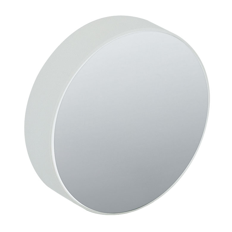
Click to Enlarge
PF10-03-G01 Protected Aluminum Mirror
| Item # | PF05-03-G01-10 | PF10-03-G01-10 |
|---|---|---|
| Diameter | 1/2" (12.7 mm) | 1" (25.4 mm) |
| Diameter Tolerance | +0.0 mm / -0.1 mm | |
| Thickness | 6.0 mm (0.24") | 6.0 mm (0.24") |
| Thickness Tolerance | ±0.2 mm | |
| Reflectance | Ravg >90% from 450 nm to 2 µm Ravg >95% from 2 to 20 µm |
|
| Reflectance Plot (Click for Plot) |  |
|
| Substrate | Fused Silica | |
| Flatness | λ/10 @ 633 nm | |
| Parallelism | <3 arcmin | |
| Clear Aperture | >90% of Diameter | |
| Damage Threshold (Pulsed) | 0.3 J/cm2 at 1064 nm, 10 ns, 10 Hz, Ø1.000 mm | |
| Damage Threshold (CW)a | 100 W/cm at 1.070 µm, Ø0.098 mm 350 W/cm at 10.6 µm, Ø0.339 mm |
|
Protected Silver
Click to Enlarge
PF10-03-P01 Protected Silver Mirror
| Item # | PF05-03-P01-10 | PF10-03-P01-10 | PF20-03-P01-10 |
|---|---|---|---|
| Diameter | 0.5" (12.7 mm) | 1" (25.4 mm) | 2" (50.8 mm) |
| Diameter Tolerance | +0.0 mm / -0.1 mm | ||
| Thickness | 6.0 mm (0.24") | 6.0 mm (0.24") | 12.0 mm (0.47") |
| Thickness Tolerance | ±0.2 mm | ||
| Reflectance | Ravg > 97.5% for 450 nm to 2 µm Ravg > 96% for 2 µm - 20 µm |
||
| Reflectance Plot (Click for Plot) |  |
||
| Substrate | Fused Silica | ||
| Surface Flatness | λ/10 @ 633 nm | ||
| Surface Quality | 40-20 Scratch-Dig | ||
| Parallelism | <3 arcmin | ||
| Clear Aperture | >90% of Diameter | ||
| Damage Threshold (Pulsed) | 0.225 J/cm2 at 800 nm, 99 fs, 1 kHz, Ø0.167 mm 3 J/cm2 at 1064 nm, 10 ns, 10 Hz, Ø1.000 mm |
||
| Damage Threshold (CW)a | 500 W/cm at 1.07 µm, Ø0.974 mm 1500 W/cm at 10.6 µm, Ø0.339 mm |
||
Ultrafast-Enhanced Silver
Click to Enlarge
UM10-AG Utrafast-Enhanced Silver Mirror
| Item # | UM10-AG-10 |
|---|---|
| Diameter | 1" (25.4 mm) |
| Diameter Tolerance | +0.00 mm / -0.10 mm |
| Thickness | 6.0 mm (0.24") |
| Thickness Tolerance | ±0.20 mm |
| Reflectance | Rs > 99.0% and Rp > 98.5% from 750 nm to 1000 nm (45° AOI) |
| Reflectance Plot (Click for Plota) |  |
| Group Delay Dispersion (Click for Plota) | S-Pol: |GDD| < 20 fs2 P-Pol: |GDD| < 30 fs2 (45° AOI) |
| Substrate | Fused Silica |
| Flatness | λ/10 @ 632.8 nm |
| Front Surface Quality | 40-20 Scratch-Dig |
| Back Surface | Fine Ground |
| Parallelism | ≤3 arcmin |
| Clear Aperture | >80% of Diameter |
| Damage Threshold (Pulsed)b (Click for Plot) | 0.39 J/cm2 (800 nm, 52 fs FWHM, S-Pol, 1 Pulse) 0.18 J/cm2 (800 nm, 52 fs FWHM, S-Pol, 1000 Pulses) |
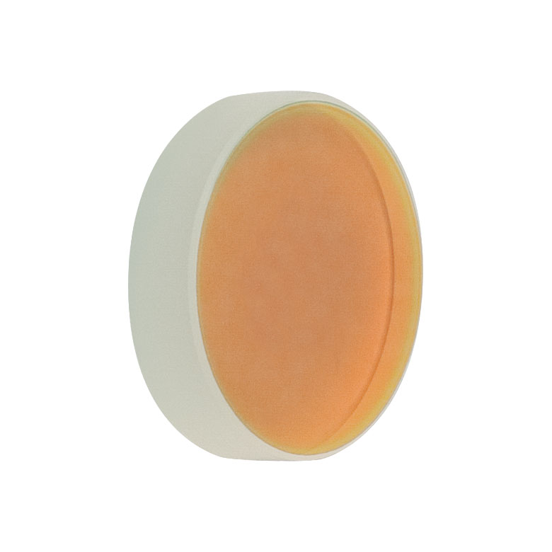
Protected Gold

Click to Enlarge
PF10-03-M01 Protected Gold Mirror
| Item # | PF05-03-M01-10 | PF10-03-M01-10 | PF20-03-M01-10 | |
|---|---|---|---|---|
| Diameter | 1/2" (12.7 mm) | 1" (25.4 mm) | 2" (50.8 mm) | |
| Diameter Tolerance | +0.0 mm/-0.1 mm | |||
| Thickness | 6.0 mm (0.24") | 6.0 mm (0.24") | 12.0 mm (0.47") | |
| Thickness Tolerance | ±0.2 mm | |||
| Reflectance | Ravg > 96% from 800 nm to 20 μm | |||
| Reflectance Plot (Click for Plot) |  |
|||
| Substrate | Fused Silica | |||
| Front Surface Flatness | λ/10 @ 633 nm | |||
| Surface Quality | 40-20 Scratch-Dig | |||
| Parallelism | <3 arcmin | |||
| Clear Aperture | >90% of Diameter | |||
| Damage Threshold (Pulsed) | 2 J/cm2 at 1.064 µm, 10 ns, 10 Hz, Ø1.000 mm | |||
| Damage Threshold (CW)a | 500 W/cm at 1.070 µm, Ø0.089 mm 750 W/cm at 10.6 µm, Ø0.339 mm |
|||
Unprotected Gold
Click to Enlarge
PF10-03-M03 Unprotected Gold Mirror
| Item # | PF05-03-M03-10 | PF10-03-M03-10 | PF20-03-M03-10 | |
|---|---|---|---|---|
| Diameter | 1/2" (12.7 mm) | 1" (25.4 mm) | 2" (50.8 mm) | |
| Diameter Tolerance | +0.0 mm/-0.1 mm | |||
| Thickness | 6.0 mm (0.24") | 12.0 mm (0.47") | ||
| Thickness Tolerance | ±0.2 mm | |||
| Reflectance (Average) | >97% for 800 nm - 20 μm | |||
| Reflectance Curve (Click for Plot) |  |
|||
| Substrate | Fused Silica | |||
| Front Surface Flatness (Peak to Valley) | λ/10 | |||
| Surface Quality | 40-20 Scratch-Dig | |||
| Parallelism | ≤3 arcmin | |||
| Clear Aperture | >90% of Diameter | |||
| Damage Threshold (Pulsed) | 4 J/cm2 at 10.6 µm, 100 ns, 1 Hz, Ø0.435 mm | |||
| Damage Threshold (CW)a | 1000 W/cm at 10.6 µm, Ø1.18 mm | |||
NOTE: The gold layer on unprotected mirrors does not include a protective overcoat. Bare gold does not oxidize in air, but can be easily damaged by fingerprints, aerosols, or the slightest contact with any abrasive material. Unprotected gold mirrors should only be handled when necessary and always held by the sides. Latex gloves or a similar protective covering should be worn to prevent oil from fingers from reaching the surface. No attempt should be made to clean the surface other than blowing off dust with clean, dry air or nitrogen. Any other cleaning method may damage the surface.
MIR-Enhanced Gold
Click to Enlarge
PF10-03-M02 MIR-Enhanced Gold Mirror
| Item # | PF05-03-M02-10 | PF10-03-M02-10 | PF20-03-M02-10 |
|---|---|---|---|
| Diameter | 1/2" (12.7 mm) | 1" (25.4 mm) | 2" (50.8 mm) |
| Diameter Tolerance | +0.0 mm / -0.1 mm | ||
| Thickness | 6.0 mm (0.24") | 6.0 mm (0.24") | 12.0 mm (0.47") |
| Thickness Tolerance | ±0.2 mm | ||
| Clear Aperture | >Ø11.4 mm | >Ø22.9 mm | >Ø45.7 mm |
| Reflectance | Ravg > 98%, Rabs > 95% from 2 µm to 20 μm @ 0° to 45° AOI | ||
| Reflectance Curve (Click for Plot) |  Click Here for Raw Data |
||
| Substrate | Fused Silica | ||
| Front Surface Flatness (Peak to Valley) |
<λ/10 @ 633 nm | ||
| Surface Quality | 40-20 Scratch-Dig | ||
| Parallelism | <3 arcmin | ||
| Damage Threshold (Pulsed) | 0.1 J/cm2 at 1.064 µm, 10 ns, 10 Hz, Ø1.06 mm 3 J/cm2 at 10.6 µm, 100 ns, 1 Hz, Ø1.29 mm |
||
| Damage Threshold (CW)a | 25 W/cm at 1.070 µm, Ø1.04 mm 450 W/cm at 10.6 µm, Ø1.18 mm |
||
| Damage Threshold Specifications | ||
|---|---|---|
| Coating (Item # Suffix) |
Damage Threshold | |
| UV-Enhanced Aluminum (-F01-10) |
Pulsed | 0.25 J/cm2 at 266 nm, 10 ns, 10 Hz, Ø0.150 mm 0.3 J/cm2 at 355 nm, 10 ns, 10 Hz, Ø0.381 mm |
| CWa | 300 W/cm at 1.064 µm, Ø0.044 mm 500 W/cm at 10.6 µm, Ø0.339 mm |
|
| Protected Aluminum (-G01-10) |
Pulsed | 0.3 J/cm2 at 1064 nm, 10 ns, 10 Hz, Ø1.000 mm |
| CWa | 100 W/cm at 1.070 µm, Ø0.098 mm 350 W/cm at 10.6 µm, Ø0.339 mm |
|
| Protected Silver (-P01-10) |
Pulsed | 0.225 J/cm2 at 800 nm, 99 fs, 1 kHz, Ø0.167 mm 3 J/cm2 at 1064 nm, 10 ns, 10 Hz, Ø1.000 mm |
| CWa | 500 W/cm at 1.07 µm, Ø0.974 mm 1500 W/cm at 10.6 µm, Ø0.339 mm |
|
| Ultrafast-Enhanced Silver (-AG-10) |
Pulsedb | 0.39 J/cm2 at 800 nm, 52 fs FWHM, S-Pol, 1 Pulse 0.18 J/cm2 at 800 nm, 52 fs FWHM, S-Pol, 1000 Pulses |
| Protected Gold (-M01-10) |
Pulsed | 2 J/cm2 at 1.064 µm, 10 ns, 10 Hz, Ø1.000 mm |
| CWa | 500 W/cm at 1.070 µm, Ø0.089 mm 750 W/cm at 10.6 µm, Ø0.339 mm |
|
| Unprotected Gold (-M03-10) |
Pulsed | 4 J/cm2 at 10.6 µm, 100 ns, 1 Hz, Ø0.435 mm |
| CWa | 1000 W/cm at 10.6 µm, Ø1.18 mm | |
| MIR-Enhanced Gold (-M02-10) |
Pulsed | 0.1 J/cm2 at 1.064 µm, 10 ns, 10 Hz, Ø1.06 mm 3 J/cm2 at 10.6 µm, 100 ns, 1 Hz, Ø1.29 mm |
| CWa | 25 W/cm at 1.07 µm, Ø1.04 mm 450 W/cm at 10.6 µm, Ø1.18 mm |
|
Damage Threshold Data for Thorlabs' Metallic Mirrors
The specifications to the right are measured data for Thorlabs' metallic mirrors. Damage threshold specifications are constant for all mirrors of a certain coating type, regardless of the size of the mirror.
Laser Induced Damage Threshold Tutorial
The following is a general overview of how laser induced damage thresholds are measured and how the values may be utilized in determining the appropriateness of an optic for a given application. When choosing optics, it is important to understand the Laser Induced Damage Threshold (LIDT) of the optics being used. The LIDT for an optic greatly depends on the type of laser you are using. Continuous wave (CW) lasers typically cause damage from thermal effects (absorption either in the coating or in the substrate). Pulsed lasers, on the other hand, often strip electrons from the lattice structure of an optic before causing thermal damage. Note that the guideline presented here assumes room temperature operation and optics in new condition (i.e., within scratch-dig spec, surface free of contamination, etc.). Because dust or other particles on the surface of an optic can cause damage at lower thresholds, we recommend keeping surfaces clean and free of debris. For more information on cleaning optics, please see our Optics Cleaning tutorial.
Testing Method
Thorlabs' LIDT testing is done in compliance with ISO/DIS 11254 and ISO 21254 specifications.
First, a low-power/energy beam is directed to the optic under test. The optic is exposed in 10 locations to this laser beam for 30 seconds (CW) or for a number of pulses (pulse repetition frequency specified). After exposure, the optic is examined by a microscope (~100X magnification) for any visible damage. The number of locations that are damaged at a particular power/energy level is recorded. Next, the power/energy is either increased or decreased and the optic is exposed at 10 new locations. This process is repeated until damage is observed. The damage threshold is then assigned to be the highest power/energy that the optic can withstand without causing damage. A histogram such as that below represents the testing of one BB1-E02 mirror.
The photograph above is a protected aluminum-coated mirror after LIDT testing. In this particular test, it handled 0.43 J/cm2 (1064 nm, 10 ns pulse, 10 Hz, Ø1.000 mm) before damage.
| Example Test Data | |||
|---|---|---|---|
| Fluence | # of Tested Locations | Locations with Damage | Locations Without Damage |
| 1.50 J/cm2 | 10 | 0 | 10 |
| 1.75 J/cm2 | 10 | 0 | 10 |
| 2.00 J/cm2 | 10 | 0 | 10 |
| 2.25 J/cm2 | 10 | 1 | 9 |
| 3.00 J/cm2 | 10 | 1 | 9 |
| 5.00 J/cm2 | 10 | 9 | 1 |
According to the test, the damage threshold of the mirror was 2.00 J/cm2 (532 nm, 10 ns pulse, 10 Hz, Ø0.803 mm). Please keep in mind that these tests are performed on clean optics, as dirt and contamination can significantly lower the damage threshold of a component. While the test results are only representative of one coating run, Thorlabs specifies damage threshold values that account for coating variances.
Continuous Wave and Long-Pulse Lasers
When an optic is damaged by a continuous wave (CW) laser, it is usually due to the melting of the surface as a result of absorbing the laser's energy or damage to the optical coating (antireflection) [1]. Pulsed lasers with pulse lengths longer than 1 µs can be treated as CW lasers for LIDT discussions.
When pulse lengths are between 1 ns and 1 µs, laser-induced damage can occur either because of absorption or a dielectric breakdown (therefore, a user must check both CW and pulsed LIDT). Absorption is either due to an intrinsic property of the optic or due to surface irregularities; thus LIDT values are only valid for optics meeting or exceeding the surface quality specifications given by a manufacturer. While many optics can handle high power CW lasers, cemented (e.g., achromatic doublets) or highly absorptive (e.g., ND filters) optics tend to have lower CW damage thresholds. These lower thresholds are due to absorption or scattering in the cement or metal coating.
LIDT in linear power density vs. pulse length and spot size. For long pulses to CW, linear power density becomes a constant with spot size. This graph was obtained from [1].
Pulsed lasers with high pulse repetition frequencies (PRF) may behave similarly to CW beams. Unfortunately, this is highly dependent on factors such as absorption and thermal diffusivity, so there is no reliable method for determining when a high PRF laser will damage an optic due to thermal effects. For beams with a high PRF both the average and peak powers must be compared to the equivalent CW power. Additionally, for highly transparent materials, there is little to no drop in the LIDT with increasing PRF.
In order to use the specified CW damage threshold of an optic, it is necessary to know the following:
- Wavelength of your laser
- Beam diameter of your beam (1/e2)
- Approximate intensity profile of your beam (e.g., Gaussian)
- Linear power density of your beam (total power divided by 1/e2 beam diameter)
Thorlabs expresses LIDT for CW lasers as a linear power density measured in W/cm. In this regime, the LIDT given as a linear power density can be applied to any beam diameter; one does not need to compute an adjusted LIDT to adjust for changes in spot size, as demonstrated by the graph to the right. Average linear power density can be calculated using the equation below.

The calculation above assumes a uniform beam intensity profile. You must now consider hotspots in the beam or other non-uniform intensity profiles and roughly calculate a maximum power density. For reference, a Gaussian beam typically has a maximum power density that is twice that of the uniform beam (see lower right).
Now compare the maximum power density to that which is specified as the LIDT for the optic. If the optic was tested at a wavelength other than your operating wavelength, the damage threshold must be scaled appropriately. A good rule of thumb is that the damage threshold has a linear relationship with wavelength such that as you move to shorter wavelengths, the damage threshold decreases (i.e., a LIDT of 10 W/cm at 1310 nm scales to 5 W/cm at 655 nm):

While this rule of thumb provides a general trend, it is not a quantitative analysis of LIDT vs wavelength. In CW applications, for instance, damage scales more strongly with absorption in the coating and substrate, which does not necessarily scale well with wavelength. While the above procedure provides a good rule of thumb for LIDT values, please contact Tech Support if your wavelength is different from the specified LIDT wavelength. If your power density is less than the adjusted LIDT of the optic, then the optic should work for your application.
Please note that we have a buffer built in between the specified damage thresholds online and the tests which we have done, which accommodates variation between batches. Upon request, we can provide individual test information and a testing certificate. The damage analysis will be carried out on a similar optic (customer's optic will not be damaged). Testing may result in additional costs or lead times. Contact Tech Support for more information.
Pulsed Lasers
As previously stated, pulsed lasers typically induce a different type of damage to the optic than CW lasers. Pulsed lasers often do not heat the optic enough to damage it; instead, pulsed lasers produce strong electric fields capable of inducing dielectric breakdown in the material. Unfortunately, it can be very difficult to compare the LIDT specification of an optic to your laser. There are multiple regimes in which a pulsed laser can damage an optic and this is based on the laser's pulse length. The highlighted columns in the table below outline the relevant pulse lengths for our specified LIDT values.
Pulses shorter than 10-9 s cannot be compared to our specified LIDT values with much reliability. In this ultra-short-pulse regime various mechanics, such as multiphoton-avalanche ionization, take over as the predominate damage mechanism [2]. In contrast, pulses between 10-7 s and 10-4 s may cause damage to an optic either because of dielectric breakdown or thermal effects. This means that both CW and pulsed damage thresholds must be compared to the laser beam to determine whether the optic is suitable for your application.
| Pulse Duration | t < 10-9 s | 10-9 < t < 10-7 s | 10-7 < t < 10-4 s | t > 10-4 s |
|---|---|---|---|---|
| Damage Mechanism | Avalanche Ionization | Dielectric Breakdown | Dielectric Breakdown or Thermal | Thermal |
| Relevant Damage Specification | No Comparison (See Above) | Pulsed | Pulsed and CW | CW |
When comparing an LIDT specified for a pulsed laser to your laser, it is essential to know the following:
LIDT in energy density vs. pulse length and spot size. For short pulses, energy density becomes a constant with spot size. This graph was obtained from [1].
- Wavelength of your laser
- Energy density of your beam (total energy divided by 1/e2 area)
- Pulse length of your laser
- Pulse repetition frequency (prf) of your laser
- Beam diameter of your laser (1/e2 )
- Approximate intensity profile of your beam (e.g., Gaussian)
The energy density of your beam should be calculated in terms of J/cm2. The graph to the right shows why expressing the LIDT as an energy density provides the best metric for short pulse sources. In this regime, the LIDT given as an energy density can be applied to any beam diameter; one does not need to compute an adjusted LIDT to adjust for changes in spot size. This calculation assumes a uniform beam intensity profile. You must now adjust this energy density to account for hotspots or other nonuniform intensity profiles and roughly calculate a maximum energy density. For reference a Gaussian beam typically has a maximum energy density that is twice that of the 1/e2 beam.
Now compare the maximum energy density to that which is specified as the LIDT for the optic. If the optic was tested at a wavelength other than your operating wavelength, the damage threshold must be scaled appropriately [3]. A good rule of thumb is that the damage threshold has an inverse square root relationship with wavelength such that as you move to shorter wavelengths, the damage threshold decreases (i.e., a LIDT of 1 J/cm2 at 1064 nm scales to 0.7 J/cm2 at 532 nm):

You now have a wavelength-adjusted energy density, which you will use in the following step.
Beam diameter is also important to know when comparing damage thresholds. While the LIDT, when expressed in units of J/cm², scales independently of spot size; large beam sizes are more likely to illuminate a larger number of defects which can lead to greater variances in the LIDT [4]. For data presented here, a <1 mm beam size was used to measure the LIDT. For beams sizes greater than 5 mm, the LIDT (J/cm2) will not scale independently of beam diameter due to the larger size beam exposing more defects.
The pulse length must now be compensated for. The longer the pulse duration, the more energy the optic can handle. For pulse widths between 1 - 100 ns, an approximation is as follows:

Use this formula to calculate the Adjusted LIDT for an optic based on your pulse length. If your maximum energy density is less than this adjusted LIDT maximum energy density, then the optic should be suitable for your application. Keep in mind that this calculation is only used for pulses between 10-9 s and 10-7 s. For pulses between 10-7 s and 10-4 s, the CW LIDT must also be checked before deeming the optic appropriate for your application.
Please note that we have a buffer built in between the specified damage thresholds online and the tests which we have done, which accommodates variation between batches. Upon request, we can provide individual test information and a testing certificate. Contact Tech Support for more information.
[1] R. M. Wood, Optics and Laser Tech. 29, 517 (1998).
[2] Roger M. Wood, Laser-Induced Damage of Optical Materials (Institute of Physics Publishing, Philadelphia, PA, 2003).
[3] C. W. Carr et al., Phys. Rev. Lett. 91, 127402 (2003).
[4] N. Bloembergen, Appl. Opt. 12, 661 (1973).

In order to illustrate the process of determining whether a given laser system will damage an optic, a number of example calculations of laser induced damage threshold are given below. For assistance with performing similar calculations, we provide a spreadsheet calculator that can be downloaded by clicking the button to the right. To use the calculator, enter the specified LIDT value of the optic under consideration and the relevant parameters of your laser system in the green boxes. The spreadsheet will then calculate a linear power density for CW and pulsed systems, as well as an energy density value for pulsed systems. These values are used to calculate adjusted, scaled LIDT values for the optics based on accepted scaling laws. This calculator assumes a Gaussian beam profile, so a correction factor must be introduced for other beam shapes (uniform, etc.). The LIDT scaling laws are determined from empirical relationships; their accuracy is not guaranteed. Remember that absorption by optics or coatings can significantly reduce LIDT in some spectral regions. These LIDT values are not valid for ultrashort pulses less than one nanosecond in duration.
A Gaussian beam profile has about twice the maximum intensity of a uniform beam profile.
CW Laser Example
Suppose that a CW laser system at 1319 nm produces a 0.5 W Gaussian beam that has a 1/e2 diameter of 10 mm. A naive calculation of the average linear power density of this beam would yield a value of 0.5 W/cm, given by the total power divided by the beam diameter:
However, the maximum power density of a Gaussian beam is about twice the maximum power density of a uniform beam, as shown in the graph to the right. Therefore, a more accurate determination of the maximum linear power density of the system is 1 W/cm.
An AC127-030-C achromatic doublet lens has a specified CW LIDT of 350 W/cm, as tested at 1550 nm. CW damage threshold values typically scale directly with the wavelength of the laser source, so this yields an adjusted LIDT value:
The adjusted LIDT value of 350 W/cm x (1319 nm / 1550 nm) = 298 W/cm is significantly higher than the calculated maximum linear power density of the laser system, so it would be safe to use this doublet lens for this application.
Pulsed Nanosecond Laser Example: Scaling for Different Pulse Durations
Suppose that a pulsed Nd:YAG laser system is frequency tripled to produce a 10 Hz output, consisting of 2 ns output pulses at 355 nm, each with 1 J of energy, in a Gaussian beam with a 1.9 cm beam diameter (1/e2). The average energy density of each pulse is found by dividing the pulse energy by the beam area:
As described above, the maximum energy density of a Gaussian beam is about twice the average energy density. So, the maximum energy density of this beam is ~0.7 J/cm2.
The energy density of the beam can be compared to the LIDT values of 1 J/cm2 and 3.5 J/cm2 for a BB1-E01 broadband dielectric mirror and an NB1-K08 Nd:YAG laser line mirror, respectively. Both of these LIDT values, while measured at 355 nm, were determined with a 10 ns pulsed laser at 10 Hz. Therefore, an adjustment must be applied for the shorter pulse duration of the system under consideration. As described on the previous tab, LIDT values in the nanosecond pulse regime scale with the square root of the laser pulse duration:
This adjustment factor results in LIDT values of 0.45 J/cm2 for the BB1-E01 broadband mirror and 1.6 J/cm2 for the Nd:YAG laser line mirror, which are to be compared with the 0.7 J/cm2 maximum energy density of the beam. While the broadband mirror would likely be damaged by the laser, the more specialized laser line mirror is appropriate for use with this system.
Pulsed Nanosecond Laser Example: Scaling for Different Wavelengths
Suppose that a pulsed laser system emits 10 ns pulses at 2.5 Hz, each with 100 mJ of energy at 1064 nm in a 16 mm diameter beam (1/e2) that must be attenuated with a neutral density filter. For a Gaussian output, these specifications result in a maximum energy density of 0.1 J/cm2. The damage threshold of an NDUV10A Ø25 mm, OD 1.0, reflective neutral density filter is 0.05 J/cm2 for 10 ns pulses at 355 nm, while the damage threshold of the similar NE10A absorptive filter is 10 J/cm2 for 10 ns pulses at 532 nm. As described on the previous tab, the LIDT value of an optic scales with the square root of the wavelength in the nanosecond pulse regime:
This scaling gives adjusted LIDT values of 0.08 J/cm2 for the reflective filter and 14 J/cm2 for the absorptive filter. In this case, the absorptive filter is the best choice in order to avoid optical damage.
Pulsed Microsecond Laser Example
Consider a laser system that produces 1 µs pulses, each containing 150 µJ of energy at a repetition rate of 50 kHz, resulting in a relatively high duty cycle of 5%. This system falls somewhere between the regimes of CW and pulsed laser induced damage, and could potentially damage an optic by mechanisms associated with either regime. As a result, both CW and pulsed LIDT values must be compared to the properties of the laser system to ensure safe operation.
If this relatively long-pulse laser emits a Gaussian 12.7 mm diameter beam (1/e2) at 980 nm, then the resulting output has a linear power density of 5.9 W/cm and an energy density of 1.2 x 10⁻⁴ J/cm2 per pulse. This can be compared to the LIDT values for a WPQ10E-980 polymer zero-order quarter-wave plate, which are 5 W/cm for CW radiation at 810 nm and 5 J/cm2 for a 10 ns pulse at 810 nm. As before, the CW LIDT of the optic scales linearly with the laser wavelength, resulting in an adjusted CW value of 6 W/cm at 980 nm. On the other hand, the pulsed LIDT scales with the square root of the laser wavelength and the square root of the pulse duration, resulting in an adjusted value of 55 J/cm2 for a 1 µs pulse at 980 nm. The pulsed LIDT of the optic is significantly greater than the energy density of the laser pulse, so individual pulses will not damage the wave plate. However, the large average linear power density of the laser system may cause thermal damage to the optic, much like a high-power CW beam.
| Posted Comments: | |
| No Comments Posted |

 Zoom
Zoom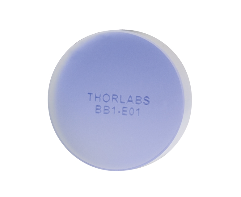
- Four Broadband Coating Options
- 350 nm - 400 nm
- 400 nm - 750 nm
- 750 nm - 1100 nm
- 1280 nm - 1600 nm
- Ø1/2" (Ø12.7 mm), Ø1" (Ø25.4 mm), and Ø2" (Ø50.8 mm) Optic Diameters Available
- Ravg > 99% for S- and P-Polarization for Angles of Incidence from 0 to 45°
- Fused Silica Substrates
Thorlabs' Broadband Dielectric Mirrors offer excellent reflectance over four different spectral ranges. Due to run-to-run coating variations, please note that the specified spectral range listed for each coating is smaller than the actual spectral region over which the mirror is effective.
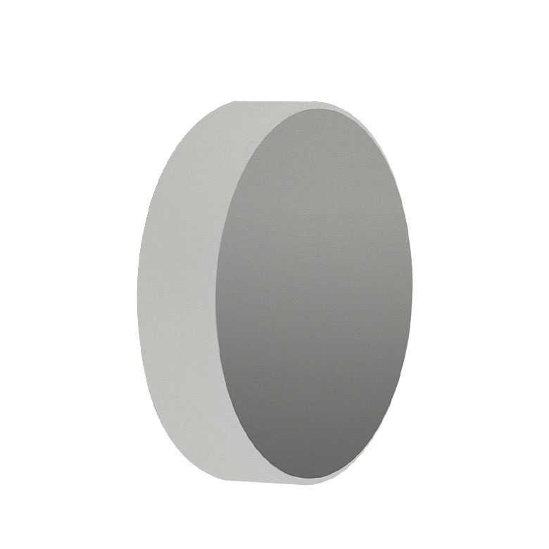
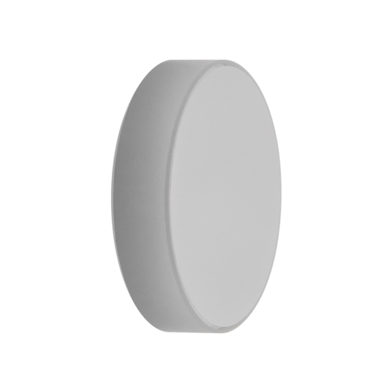
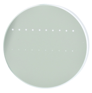
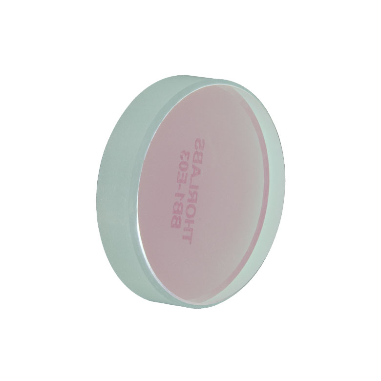
As shown above and to the right, the back of each mirror is fine ground and engraved with its respective part number for easy identification in the lab. For complete details and specifications on each of the dielectric mirrors offered in packs, see the tabs above.
The plot below is the reflectance of each broadband mirror coating in the BB series as a function of wavelength for unpolarized light incident at an angle of 6° or 8°. This choice of incident angle was due to the measurement limitations at 0°; however the plots closely represent reflectance at 0°. More detailed plots that also include polarization information are available under each of the coating-specific tabs above.
For more options or to order an individual mirror, please visit our broadband dielectric mirrors page.
Click to Enlarge
BB1-E01 Mirror
| Item # | BB05-E01-10 | BB1-E01-10 | BB2-E01-10 | ||||
|---|---|---|---|---|---|---|---|
| Diameter | 1/2" (12.7 mm) | 1" (25.4 mm) | 2" (50.8 mm) | ||||
| Diameter Tolerance | +0.0 mm / -0.1 mm | ||||||
| Thickness | 6.0 mm (0.24") | 6.0 mm (0.24") | 12.0 mm (0.47") | ||||
| Thickness Tolerance | ±0.2 mm | ||||||
| Reflectance | Ravg > 99% (350 - 400 nm) | ||||||
| Reflectance Plots (Click for Plot) |
|
||||||
| Substrate | Fused Silica | ||||||
| Front Surface Flatness (@ 633 nm) | λ/10 | ||||||
| Surface Quality | 10-5 Scratch-Dig | ||||||
| Parallelism | <3 arcmin | ||||||
| Clear Aperture | >85% of Diameter | ||||||
| Damage Threshold (Pulsed) | 1 J/cm2 (355 nm, 10 ns, 10 Hz, Ø0.373 mm) | ||||||
Click to Enlarge
BB1-E02 Mirror
| Item # | BB05-E02-10 | BB1-E02-10 | BB2-E02-10 | ||||
|---|---|---|---|---|---|---|---|
| Diameter | 1/2" (12.7 mm) | 1" (25.4 mm) | 2" (50.8 mm) | ||||
| Diameter Tolerance | +0.0 mm / -0.1 mm | ||||||
| Thickness | 6.0 mm (0.24") | 6.0 mm (0.24") | 12.0 mm (0.47") | ||||
| Thickness Tolerance | ±0.2 mm | ||||||
| Reflectance | Ravg > 99% (400 - 750 nm) | ||||||
| Reflectance Plots (Click for Plot) |
|
||||||
| Substrate | Fused Silica | ||||||
| Front Surface Flatness (@ 633 nm) | λ/10 | ||||||
| Surface Quality | 10-5 Scratch-Dig | ||||||
| Parallelism | <3 arcmin | ||||||
| Clear Aperture | >85% of Diameter | ||||||
| Damage Threshold | 0.25 J/cm2 (355 nm, 10 ns, 10 Hz, Ø0.803 mm) 550 W/cma,b (532 nm, CW, Ø1.000 mm) |
||||||
Click to Enlarge
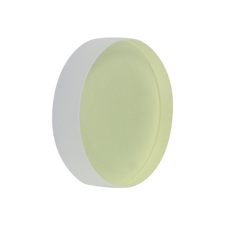
BB1-E03 Mirror
| Item # | BB05-E03-10 | BB1-E03-10 | BB2-E03-10 | ||||
|---|---|---|---|---|---|---|---|
| Diameter | 1/2" (12.7 mm) | 1" (25.4 mm) | 2" (50.8 mm) | ||||
| Diameter Tolerance | +0.0 mm / -0.1 mm | ||||||
| Thickness | 6.0 mm (0.24") | 6.0 mm (0.24") | 12.0 mm (0.47") | ||||
| Thickness Tolerance | ±0.2 mm | ||||||
| Reflectance | Ravg > 99% (750 - 1000 nm) | ||||||
| Reflectance Plots (Click for Plot) |
|
||||||
| Substrate | Fused Silica | ||||||
| Front Surface Flatness (@ 633 nm) | λ/10 | ||||||
| Surface Quality | 10-5 Scratch-Dig | ||||||
| Parallelism | <3 arcmin | ||||||
| Clear Aperture | >85% of Diameter | ||||||
| Damage Threshold |
0.205 J/cm2 (800 nm, 99 fs, 1 kHz, Ø0.166 mm) 1 J/cm2 (810 nm, 10 ns, 10 Hz, Ø0.133 mm) 0.5 J/cm2 (1064 nm, 10 ns, 10 Hz, Ø0.433 mm) 10 kW/cma,b (1070 nm, CW, Ø0.971 mm) |
||||||
Click to Enlarge
BB1-E04 Mirror
| Item # | BB05-E04-10 | BB1-E04-10 | BB2-E04-10 | ||||
|---|---|---|---|---|---|---|---|
| Diameter | 1/2" (12.7 mm) | 1" (25.4 mm) | 2" (50.8 mm) | ||||
| Diameter Tolerance | +0.0 mm / -0.1 mm | ||||||
| Thickness | 6.0 mm (0.24") | 6.0 mm (0.24") | 12.0 mm (0.47") | ||||
| Thickness Tolerance | ±0.2 mm | ||||||
| Reflectance | Ravg > 99% (1280 - 1600 nm) | ||||||
| Reflectance Plots (Click for Plot) |
|
||||||
| Substrate | Fused Silica | ||||||
| Front Surface Flatness (@ 633 nm) | λ/10 | ||||||
| Surface Quality | 10-5 Scratch-Dig | ||||||
| Parallelism | <3 arcmin | ||||||
| Clear Aperture | >85% of Diameter | ||||||
| Damage Threshold |
2.5 J/cm2 (1542 nm, 10 ns, 10 Hz, Ø0.181 mm) 350 W/cma,b (1540 nm, CW, Ø1.030 mm) |
||||||
| Damage Threshold Specifications | ||
|---|---|---|
| Item # Suffix | Type | Damage Threshold |
| -E01-10 | Pulsed | 1 J/cm2 (355 nm, 10 ns, 10 Hz, Ø0.373 mm) |
| -E02-10 | Pulsed | 0.25 J/cm2 (532 nm, 10 ns, 10 Hz, Ø0.803 mm) |
| CWa,b | 550 W/cm (532 nm, Ø1.000 mm) | |
| -E03-10 | Pulsed | 0.205 J/cm2 (800 nm, 99 fs, 1 kHz, Ø0.166 mm) 1 J/cm2 (810 nm, 10 ns, 10 Hz, Ø0.133 mm) 0.5 J/cm2 (1064 nm, 10 ns, 10 Hz, Ø0.433 mm) |
| CWa,b | 10 kW/cm (1070 nm, Ø0.971 mm) | |
| -E04-10 | Pulsed | 2.5 J/cm2 (1542 nm, 10 ns, 10 Hz, Ø0.181 mm) |
| CWa,b | 350 W/cm (1540 nm, Ø1.030 mm) | |
Damage Threshold Data for Thorlabs' Broadband Dielectric Mirrors
The specifications to the right are measured data for Thorlabs' broadband dielectric mirrors. Damage threshold specifications are constant for a given coating type, regardless of the size and shape of the mirror.
Laser Induced Damage Threshold Tutorial
The following is a general overview of how laser induced damage thresholds are measured and how the values may be utilized in determining the appropriateness of an optic for a given application. When choosing optics, it is important to understand the Laser Induced Damage Threshold (LIDT) of the optics being used. The LIDT for an optic greatly depends on the type of laser you are using. Continuous wave (CW) lasers typically cause damage from thermal effects (absorption either in the coating or in the substrate). Pulsed lasers, on the other hand, often strip electrons from the lattice structure of an optic before causing thermal damage. Note that the guideline presented here assumes room temperature operation and optics in new condition (i.e., within scratch-dig spec, surface free of contamination, etc.). Because dust or other particles on the surface of an optic can cause damage at lower thresholds, we recommend keeping surfaces clean and free of debris. For more information on cleaning optics, please see our Optics Cleaning tutorial.
Testing Method
Thorlabs' LIDT testing is done in compliance with ISO/DIS 11254 and ISO 21254 specifications.
First, a low-power/energy beam is directed to the optic under test. The optic is exposed in 10 locations to this laser beam for 30 seconds (CW) or for a number of pulses (pulse repetition frequency specified). After exposure, the optic is examined by a microscope (~100X magnification) for any visible damage. The number of locations that are damaged at a particular power/energy level is recorded. Next, the power/energy is either increased or decreased and the optic is exposed at 10 new locations. This process is repeated until damage is observed. The damage threshold is then assigned to be the highest power/energy that the optic can withstand without causing damage. A histogram such as that below represents the testing of one BB1-E02 mirror.
The photograph above is a protected aluminum-coated mirror after LIDT testing. In this particular test, it handled 0.43 J/cm2 (1064 nm, 10 ns pulse, 10 Hz, Ø1.000 mm) before damage.
| Example Test Data | |||
|---|---|---|---|
| Fluence | # of Tested Locations | Locations with Damage | Locations Without Damage |
| 1.50 J/cm2 | 10 | 0 | 10 |
| 1.75 J/cm2 | 10 | 0 | 10 |
| 2.00 J/cm2 | 10 | 0 | 10 |
| 2.25 J/cm2 | 10 | 1 | 9 |
| 3.00 J/cm2 | 10 | 1 | 9 |
| 5.00 J/cm2 | 10 | 9 | 1 |
According to the test, the damage threshold of the mirror was 2.00 J/cm2 (532 nm, 10 ns pulse, 10 Hz, Ø0.803 mm). Please keep in mind that these tests are performed on clean optics, as dirt and contamination can significantly lower the damage threshold of a component. While the test results are only representative of one coating run, Thorlabs specifies damage threshold values that account for coating variances.
Continuous Wave and Long-Pulse Lasers
When an optic is damaged by a continuous wave (CW) laser, it is usually due to the melting of the surface as a result of absorbing the laser's energy or damage to the optical coating (antireflection) [1]. Pulsed lasers with pulse lengths longer than 1 µs can be treated as CW lasers for LIDT discussions.
When pulse lengths are between 1 ns and 1 µs, laser-induced damage can occur either because of absorption or a dielectric breakdown (therefore, a user must check both CW and pulsed LIDT). Absorption is either due to an intrinsic property of the optic or due to surface irregularities; thus LIDT values are only valid for optics meeting or exceeding the surface quality specifications given by a manufacturer. While many optics can handle high power CW lasers, cemented (e.g., achromatic doublets) or highly absorptive (e.g., ND filters) optics tend to have lower CW damage thresholds. These lower thresholds are due to absorption or scattering in the cement or metal coating.
LIDT in linear power density vs. pulse length and spot size. For long pulses to CW, linear power density becomes a constant with spot size. This graph was obtained from [1].
Pulsed lasers with high pulse repetition frequencies (PRF) may behave similarly to CW beams. Unfortunately, this is highly dependent on factors such as absorption and thermal diffusivity, so there is no reliable method for determining when a high PRF laser will damage an optic due to thermal effects. For beams with a high PRF both the average and peak powers must be compared to the equivalent CW power. Additionally, for highly transparent materials, there is little to no drop in the LIDT with increasing PRF.
In order to use the specified CW damage threshold of an optic, it is necessary to know the following:
- Wavelength of your laser
- Beam diameter of your beam (1/e2)
- Approximate intensity profile of your beam (e.g., Gaussian)
- Linear power density of your beam (total power divided by 1/e2 beam diameter)
Thorlabs expresses LIDT for CW lasers as a linear power density measured in W/cm. In this regime, the LIDT given as a linear power density can be applied to any beam diameter; one does not need to compute an adjusted LIDT to adjust for changes in spot size, as demonstrated by the graph to the right. Average linear power density can be calculated using the equation below.
The calculation above assumes a uniform beam intensity profile. You must now consider hotspots in the beam or other non-uniform intensity profiles and roughly calculate a maximum power density. For reference, a Gaussian beam typically has a maximum power density that is twice that of the uniform beam (see lower right).
Now compare the maximum power density to that which is specified as the LIDT for the optic. If the optic was tested at a wavelength other than your operating wavelength, the damage threshold must be scaled appropriately. A good rule of thumb is that the damage threshold has a linear relationship with wavelength such that as you move to shorter wavelengths, the damage threshold decreases (i.e., a LIDT of 10 W/cm at 1310 nm scales to 5 W/cm at 655 nm):
While this rule of thumb provides a general trend, it is not a quantitative analysis of LIDT vs wavelength. In CW applications, for instance, damage scales more strongly with absorption in the coating and substrate, which does not necessarily scale well with wavelength. While the above procedure provides a good rule of thumb for LIDT values, please contact Tech Support if your wavelength is different from the specified LIDT wavelength. If your power density is less than the adjusted LIDT of the optic, then the optic should work for your application.
Please note that we have a buffer built in between the specified damage thresholds online and the tests which we have done, which accommodates variation between batches. Upon request, we can provide individual test information and a testing certificate. The damage analysis will be carried out on a similar optic (customer's optic will not be damaged). Testing may result in additional costs or lead times. Contact Tech Support for more information.
Pulsed Lasers
As previously stated, pulsed lasers typically induce a different type of damage to the optic than CW lasers. Pulsed lasers often do not heat the optic enough to damage it; instead, pulsed lasers produce strong electric fields capable of inducing dielectric breakdown in the material. Unfortunately, it can be very difficult to compare the LIDT specification of an optic to your laser. There are multiple regimes in which a pulsed laser can damage an optic and this is based on the laser's pulse length. The highlighted columns in the table below outline the relevant pulse lengths for our specified LIDT values.
Pulses shorter than 10-9 s cannot be compared to our specified LIDT values with much reliability. In this ultra-short-pulse regime various mechanics, such as multiphoton-avalanche ionization, take over as the predominate damage mechanism [2]. In contrast, pulses between 10-7 s and 10-4 s may cause damage to an optic either because of dielectric breakdown or thermal effects. This means that both CW and pulsed damage thresholds must be compared to the laser beam to determine whether the optic is suitable for your application.
| Pulse Duration | t < 10-9 s | 10-9 < t < 10-7 s | 10-7 < t < 10-4 s | t > 10-4 s |
|---|---|---|---|---|
| Damage Mechanism | Avalanche Ionization | Dielectric Breakdown | Dielectric Breakdown or Thermal | Thermal |
| Relevant Damage Specification | No Comparison (See Above) | Pulsed | Pulsed and CW | CW |
When comparing an LIDT specified for a pulsed laser to your laser, it is essential to know the following:
LIDT in energy density vs. pulse length and spot size. For short pulses, energy density becomes a constant with spot size. This graph was obtained from [1].
- Wavelength of your laser
- Energy density of your beam (total energy divided by 1/e2 area)
- Pulse length of your laser
- Pulse repetition frequency (prf) of your laser
- Beam diameter of your laser (1/e2 )
- Approximate intensity profile of your beam (e.g., Gaussian)
The energy density of your beam should be calculated in terms of J/cm2. The graph to the right shows why expressing the LIDT as an energy density provides the best metric for short pulse sources. In this regime, the LIDT given as an energy density can be applied to any beam diameter; one does not need to compute an adjusted LIDT to adjust for changes in spot size. This calculation assumes a uniform beam intensity profile. You must now adjust this energy density to account for hotspots or other nonuniform intensity profiles and roughly calculate a maximum energy density. For reference a Gaussian beam typically has a maximum energy density that is twice that of the 1/e2 beam.
Now compare the maximum energy density to that which is specified as the LIDT for the optic. If the optic was tested at a wavelength other than your operating wavelength, the damage threshold must be scaled appropriately [3]. A good rule of thumb is that the damage threshold has an inverse square root relationship with wavelength such that as you move to shorter wavelengths, the damage threshold decreases (i.e., a LIDT of 1 J/cm2 at 1064 nm scales to 0.7 J/cm2 at 532 nm):
You now have a wavelength-adjusted energy density, which you will use in the following step.
Beam diameter is also important to know when comparing damage thresholds. While the LIDT, when expressed in units of J/cm², scales independently of spot size; large beam sizes are more likely to illuminate a larger number of defects which can lead to greater variances in the LIDT [4]. For data presented here, a <1 mm beam size was used to measure the LIDT. For beams sizes greater than 5 mm, the LIDT (J/cm2) will not scale independently of beam diameter due to the larger size beam exposing more defects.
The pulse length must now be compensated for. The longer the pulse duration, the more energy the optic can handle. For pulse widths between 1 - 100 ns, an approximation is as follows:
Use this formula to calculate the Adjusted LIDT for an optic based on your pulse length. If your maximum energy density is less than this adjusted LIDT maximum energy density, then the optic should be suitable for your application. Keep in mind that this calculation is only used for pulses between 10-9 s and 10-7 s. For pulses between 10-7 s and 10-4 s, the CW LIDT must also be checked before deeming the optic appropriate for your application.
Please note that we have a buffer built in between the specified damage thresholds online and the tests which we have done, which accommodates variation between batches. Upon request, we can provide individual test information and a testing certificate. Contact Tech Support for more information.
[1] R. M. Wood, Optics and Laser Tech. 29, 517 (1998).
[2] Roger M. Wood, Laser-Induced Damage of Optical Materials (Institute of Physics Publishing, Philadelphia, PA, 2003).
[3] C. W. Carr et al., Phys. Rev. Lett. 91, 127402 (2003).
[4] N. Bloembergen, Appl. Opt. 12, 661 (1973).
In order to illustrate the process of determining whether a given laser system will damage an optic, a number of example calculations of laser induced damage threshold are given below. For assistance with performing similar calculations, we provide a spreadsheet calculator that can be downloaded by clicking the button to the right. To use the calculator, enter the specified LIDT value of the optic under consideration and the relevant parameters of your laser system in the green boxes. The spreadsheet will then calculate a linear power density for CW and pulsed systems, as well as an energy density value for pulsed systems. These values are used to calculate adjusted, scaled LIDT values for the optics based on accepted scaling laws. This calculator assumes a Gaussian beam profile, so a correction factor must be introduced for other beam shapes (uniform, etc.). The LIDT scaling laws are determined from empirical relationships; their accuracy is not guaranteed. Remember that absorption by optics or coatings can significantly reduce LIDT in some spectral regions. These LIDT values are not valid for ultrashort pulses less than one nanosecond in duration.
A Gaussian beam profile has about twice the maximum intensity of a uniform beam profile.
CW Laser Example
Suppose that a CW laser system at 1319 nm produces a 0.5 W Gaussian beam that has a 1/e2 diameter of 10 mm. A naive calculation of the average linear power density of this beam would yield a value of 0.5 W/cm, given by the total power divided by the beam diameter:
However, the maximum power density of a Gaussian beam is about twice the maximum power density of a uniform beam, as shown in the graph to the right. Therefore, a more accurate determination of the maximum linear power density of the system is 1 W/cm.
An AC127-030-C achromatic doublet lens has a specified CW LIDT of 350 W/cm, as tested at 1550 nm. CW damage threshold values typically scale directly with the wavelength of the laser source, so this yields an adjusted LIDT value:
The adjusted LIDT value of 350 W/cm x (1319 nm / 1550 nm) = 298 W/cm is significantly higher than the calculated maximum linear power density of the laser system, so it would be safe to use this doublet lens for this application.
Pulsed Nanosecond Laser Example: Scaling for Different Pulse Durations
Suppose that a pulsed Nd:YAG laser system is frequency tripled to produce a 10 Hz output, consisting of 2 ns output pulses at 355 nm, each with 1 J of energy, in a Gaussian beam with a 1.9 cm beam diameter (1/e2). The average energy density of each pulse is found by dividing the pulse energy by the beam area:
As described above, the maximum energy density of a Gaussian beam is about twice the average energy density. So, the maximum energy density of this beam is ~0.7 J/cm2.
The energy density of the beam can be compared to the LIDT values of 1 J/cm2 and 3.5 J/cm2 for a BB1-E01 broadband dielectric mirror and an NB1-K08 Nd:YAG laser line mirror, respectively. Both of these LIDT values, while measured at 355 nm, were determined with a 10 ns pulsed laser at 10 Hz. Therefore, an adjustment must be applied for the shorter pulse duration of the system under consideration. As described on the previous tab, LIDT values in the nanosecond pulse regime scale with the square root of the laser pulse duration:
This adjustment factor results in LIDT values of 0.45 J/cm2 for the BB1-E01 broadband mirror and 1.6 J/cm2 for the Nd:YAG laser line mirror, which are to be compared with the 0.7 J/cm2 maximum energy density of the beam. While the broadband mirror would likely be damaged by the laser, the more specialized laser line mirror is appropriate for use with this system.
Pulsed Nanosecond Laser Example: Scaling for Different Wavelengths
Suppose that a pulsed laser system emits 10 ns pulses at 2.5 Hz, each with 100 mJ of energy at 1064 nm in a 16 mm diameter beam (1/e2) that must be attenuated with a neutral density filter. For a Gaussian output, these specifications result in a maximum energy density of 0.1 J/cm2. The damage threshold of an NDUV10A Ø25 mm, OD 1.0, reflective neutral density filter is 0.05 J/cm2 for 10 ns pulses at 355 nm, while the damage threshold of the similar NE10A absorptive filter is 10 J/cm2 for 10 ns pulses at 532 nm. As described on the previous tab, the LIDT value of an optic scales with the square root of the wavelength in the nanosecond pulse regime:
This scaling gives adjusted LIDT values of 0.08 J/cm2 for the reflective filter and 14 J/cm2 for the absorptive filter. In this case, the absorptive filter is the best choice in order to avoid optical damage.
Pulsed Microsecond Laser Example
Consider a laser system that produces 1 µs pulses, each containing 150 µJ of energy at a repetition rate of 50 kHz, resulting in a relatively high duty cycle of 5%. This system falls somewhere between the regimes of CW and pulsed laser induced damage, and could potentially damage an optic by mechanisms associated with either regime. As a result, both CW and pulsed LIDT values must be compared to the properties of the laser system to ensure safe operation.
If this relatively long-pulse laser emits a Gaussian 12.7 mm diameter beam (1/e2) at 980 nm, then the resulting output has a linear power density of 5.9 W/cm and an energy density of 1.2 x 10⁻⁴ J/cm2 per pulse. This can be compared to the LIDT values for a WPQ10E-980 polymer zero-order quarter-wave plate, which are 5 W/cm for CW radiation at 810 nm and 5 J/cm2 for a 10 ns pulse at 810 nm. As before, the CW LIDT of the optic scales linearly with the laser wavelength, resulting in an adjusted CW value of 6 W/cm at 980 nm. On the other hand, the pulsed LIDT scales with the square root of the laser wavelength and the square root of the pulse duration, resulting in an adjusted value of 55 J/cm2 for a 1 µs pulse at 980 nm. The pulsed LIDT of the optic is significantly greater than the energy density of the laser pulse, so individual pulses will not damage the wave plate. However, the large average linear power density of the laser system may cause thermal damage to the optic, much like a high-power CW beam.
| Posted Comments: | |
| No Comments Posted |

 Zoom
Zoom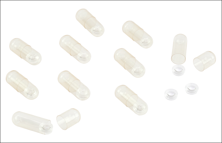
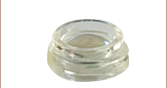
Click to Enlarge
Plastic aspheric lens packs come prepackaged in capsules as shown here.
- Made from Optical-Grade Plastic
- Outer Diameters of 6.28 mm and 7.40 mm Available
- Effective Focal Lengths from 4.60 mm to 18.15 mm
- Sold in Packs of 25, 50, or 100
Our Plastic Aspheric Lens Packs utilize molding technology to produce all-plastic, near-diffraction-limited optics. Designed by Philips for high-volume applications at affordable prices, these optics are ideal for low-power applications requiring lightweight components. The surface of the aspheric lens is designed to eliminate spherical aberration, which allows for the spot size and collimation of a monochromatic beam of light to be nearly diffraction limited. These lens packs are offered in packages of 25, 50, or 100 pieces at a discount of 16%, 33%, and 50%, respectively, over the individual lens price.
In laser diode systems, difficulties with aberration correction are compounded by the beam's high divergence angle. Since individual spherical lenses can refract light at only small angles before spherical aberration is introduced, multiple elements are often required to collimate laser diode light. In contrast, a single aspheric lens collimates without introducing spherical aberration. When used to collimate or focus light, the lens should be oriented so that the side with a larger radius of curvature (i.e., the flatter surface) faces the point source.
Conversely, when coupling into fiber, it is often necessary to focus the laser light to a near-diffraction-limited spot. With single spherical elements, spherical aberration is the limiting factor to achieving such a small spot size, rather than the diffraction limit. Because these aspheric lenses are corrected to eliminate the spherical aberration, the focal spot size can approach the diffraction limit.
All of the plastic aspheric lenses on this page are corrected for the presence of a window, like the window in TO-type laser packages. Please see the Specs tab for details. Additionally, the side of each lens has a flat indent that provides a reference location.
To order individual plastic aspheric lenses or for additional focal length options, please visit our uncoated plastic aspheric lens page.
| Item # | CAY046 | CAX100 | CAX183 |
|---|---|---|---|
| Effective Focal Length | 4.60 mm | 10.00 mm | 18.15 mm |
| Numerical Aperture | 0.40 | 0.20 | 0.12 |
| Clear Aperture | Ø3.7 mm | Ø4.1 mm | Ø4.3 mm |
| Working Distancea | 3.00 mm | 8.48 mm | 16.30 mm |
| Outer Diameter | 7.40 mm | 6.28 mm | 6.28 mm |
| Center Thickness | 2.70 mm | 1.25 mm | 1.09 mm |
| Wavefront Error, On Axisb (RMS) | 0.040λ | 0.080λ | 0.030λ |
| Wavefront Error, Totalb (RMS) | 0.070λ | 0.090λ | 0.035λ |
| Surface Quality | 80-50 Scratch-Dig | ||
| Material (Click for Transmission Plot) | Acrylic | Polycarbonate | Polycarbonate |
| Design Wavelength | 670 nm | 670 nm | 670 nm |
| AR Coating Wavelength (>95% Transmission) |
None | ||
| Laser Window Correction | 0.25 mm (N-BK7) |
0.25 mm (N-BK7) |
0.25 mm (N-BK7) |
| Operating Temperature | 5 to 65 °C | 0 to 65 °C | -10 to 75 °C |
| Storage Temperature | -10 to 70 °C | 0 to 65 °C | -25 to 100 °C |
Please note the effective focal length is determined from the back principal plane, which does not coincide with the flat surface of the lens.
Click to Enlarge
The transmission curve above shows total transmission through polycarbonate, including surface reflections. Our CAX100, CSX122, and CAX183 plastic aspheric lenses are fabricated from this material.
Click to Enlarge
The transmission curve above shows total transmission through acrylic, including surface reflections. Our CAY046 plastic aspheric lenses are fabricated from this material.
Click to Enlarge
The transmission curve above shows total transmission through cyclic olefin copolymer, including surface reflections. Our CAW100 and CAW110 plastic aspheric lenses are fabricated from this material.
| Posted Comments: | |
| No Comments Posted |

 Zoom
Zoom
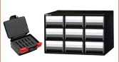
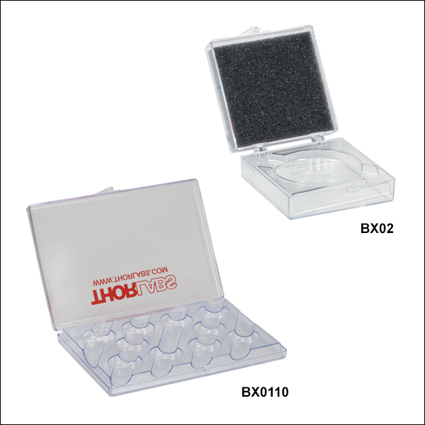
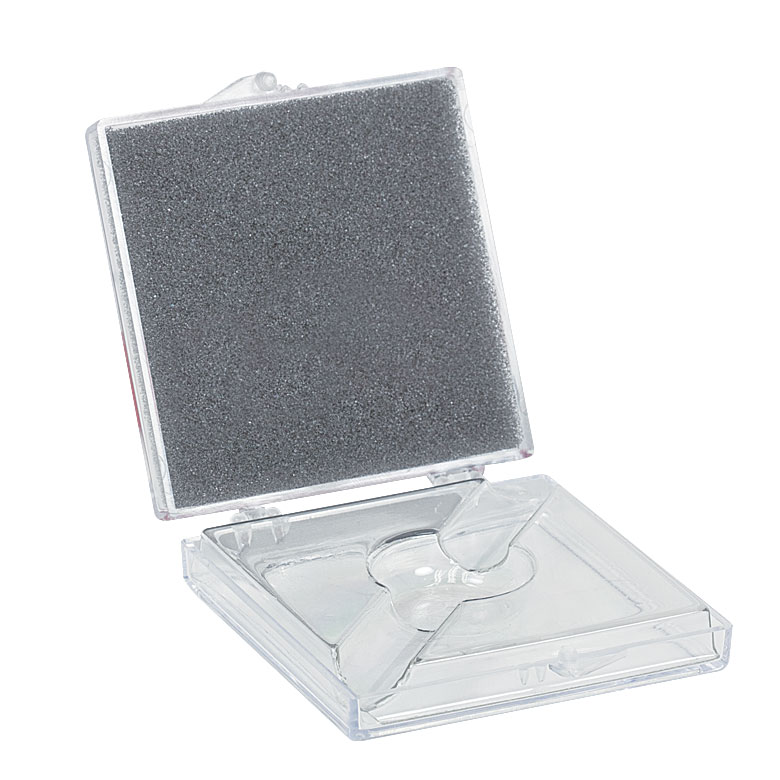
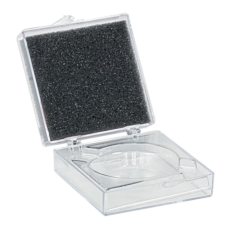
Thorlabs offers a variety of cases that are designed to store optics while they are being transported or not in use. Cases come in multipacks of 5 or 10.
For unmounted individual optics, Thorlabs offers ten-packs of the BX01 storage box for Ø1" optics, the BX02 storage box for Ø2" optics, and the BX03 storage box with foam inserts for up to Ø2.5" optics. If the need arises to store or transfer multiple unmounted optics at one time, we offer the BX0510 and BX0110 storage boxes, which can hold up to ten Ø1/2" or Ø1" optics, respectively. This reduces the amount of space needed to store the optics and makes large quantities of optics easier to transport.
| Product Image (Click to Enlarge) |
 |
 |
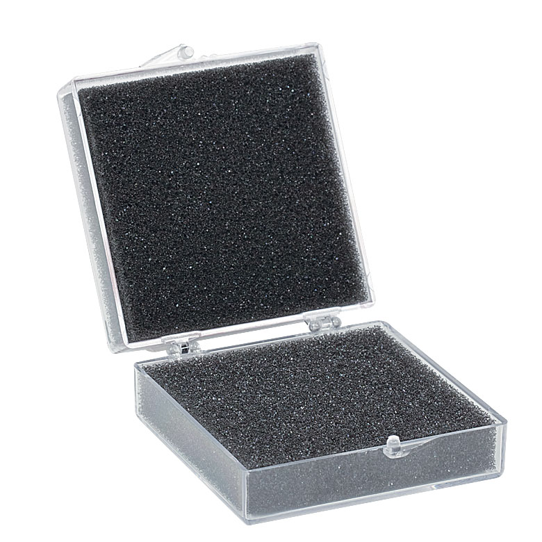 |
| Item # | BX01 | BX02 | BX03 |
| Capacity | 1 | 1 | 1 |
| Quantity | 10 | 10 | 10 |
| Optic Size | Ø1" | Ø2" | Up to Ø2.5"a |
These Optic Storage Boxes are ideal for keeping your unmounted optics clean and damage free when they are not currently in use. The boxes are available with foam inserts or with plastic molds for Ø1" or Ø2"" optics. Each box is silk screened with a Thorlabs logo and contact information. Boxes without silk screened information are available by contacting Tech Support.
| Product Image (Click to Enlarge) |
 |
 |
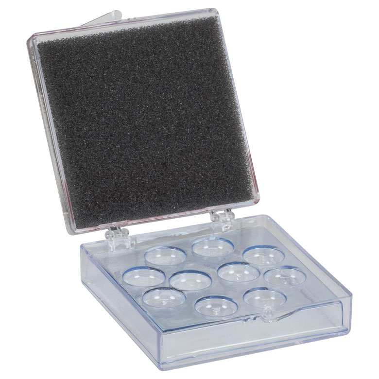
| Item # | BX0510 | BX0110 |
| Capacity | 10 | 10 |
| Quantity | 5 | 5 |
| Optic Size | Ø1/2" | Ø1" |
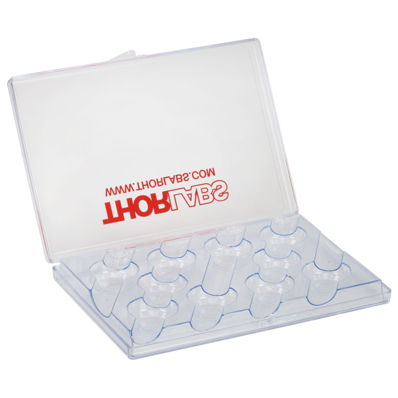
These Optics Storage Boxes are ideal for keeping up to ten unmounted optics clean and damage free when they are not in use, while also conserving space in the lab. The BX0510 and BX0110 Optics Storage Boxes have a plastic mold insert to secure up to ten Ø1/2" or Ø1" optics, respectively. The BX0510 measures 2.5" x 2.5" x 0.89" (L x W x H) while the BX0110 measures 6" x 4" x 0.67" (L x W x H). Each box is silk screened with a Thorlabs logo and contact information. Boxes without silk screened information are available by contacting Tech Support.
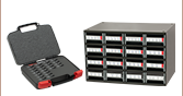
For more durable optic storage solutions, please see our Optics Cases page.
| Posted Comments: | |
| No Comments Posted |