Goniometric Stages

- Pure Rotational Motion About a Fixed Point Above the Stage
- 1° Graduation Marking on Side
- Accuracy of 10 arcmin
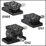
GN1
Single-Axis, 1" to Point of Rotation
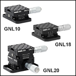
GNL10
Single-Axis, 1" to Point of Rotation
GN05
Single-Axis, 1/2" to Point of Rotation
GNL18
Single-Axis, 1.75" to Point of Rotation
GNL20
Dual-Axis, 1" to Point of Rotation
GN2
Dual-Axis, 1/2" to Point of Rotation

Please Wait

All Goniometers Feature a Fixed Point
of Rotation Above the Stage Platform
Features
- Pure Rotational Motion About a Virtual Point
- 1° Graduation Marks on Side
- Backlash-Free Spring-Loaded Design
- Fully Lockable
- Small Platform Goniometric Stage: 1" x 1"
- Large Platform Goniometric Stage: 1.5" x 1.5" (Also Available Motorized)
A goniometer or goniometric stage is a device used to rotate an object precisely, within a small angular range, about a fixed point in space. Goniometers are similar to linear stages, but, rather than providing linear movement, the stage partially rotates about a fixed point above the mounting surface of the stage. In our two product lines, the distance from the point of rotation to the mounting surface was designed so that two different goniometer models may be stacked in an XY configuration and both stages will rotate about the same point. Our goniometers use a backlash-free leadscrew in the smaller GN series and a precision micrometer for enhanced angular positioning of the top plate in the larger GNL series.
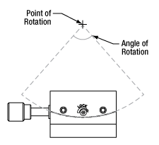
Our goniometers offer unobstructed, pure rotational motion about their point of rotation over the angle of rotation (see image to the right). The compact, stackable design allows one model to be fastened to the top plate of another aligning their points of rotation. In the GN series, the GN05(/M) stage mounts atop the GN1(/M) stage. In the GNL series, the GNL10(/M) stage mounts atop the GNL18(/M) stage. These two axis stage setups can be purchased as a single package [Item #s GN2(/M) or GNL20(/M) respectively].
The precision dovetail design, accompanied by a backlash-free lead screw and a vernier scale, provides accurate and repeatable positioning. A side mounted setscrew can be used to lock the platform in position.
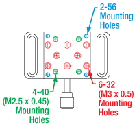
The GN series goniometers provide an array of four 2-56, four 4-40 (M2.5 x 0.45), and eight 6-32 (M3 x 0.5) taps for mounting. This series can be either post mounted via an 8-32 (M4) tap or mounted to an MS12B(/M) Mini-Series breadboard via the #4 (M3) slotted mounting holes on the base plate.
Alternatively, the GNL series offers twelve 4-40 (M2.5 x 0.45) and sixteen 6-32 (M4 x 0.7) taps. See below or the Specs tab for mounting hole position. Our PM3(/M) and PM4(/M) clamping arms feature 6-32 (M4) threads, allowing them to be attached to most goniometers. This series can be mounted onto a standard breadboard or Mini-Series breadboard with 1/4"-20 (M6) taps via the 1/4" (M6) slotted mounting holes on the base plate.
Note: Prior to mounting components onto the goniometers, please review our standard support documentation, which can be accessed by clicking the red Docs icon (![]() ) next to each Item # below. Using mounting hardware that exceeds the tap depth of the mounting holes will damage the stage.
) next to each Item # below. Using mounting hardware that exceeds the tap depth of the mounting holes will damage the stage.
We do not recommend attempting to remove the base plate from the goniometer. Doing so may compromise the precise adjustment achieved with the stage, which will then require recalibration or readjusting.
Single-Axis Goniometers
| Item # | GN05(/M) | GN1(/M) | GNL10(/M) | GNL18(/M) |
|---|---|---|---|---|
| Distance to Point of Rotation from Top Surface |
0.50" (12.7 mm) | 1.00" (25.4 mm) | 1.00" (25.4 mm) | 1.75" (44.5 mm) |
| Rotation | ±15° | ±10° | ±10° | ±5° |
| Accuracy | 10 arcmin (0.167°) | |||
| Load Capacity | 0.25 lbs (0.113 kg) | 1.0 lb (0.45 kg) | ||
| Goniometer Dimensions (W x D x H) |
1.00" x 1.00" x 0.50" (25.4 mm x 25.4 mm x 12.7 mm) |
1.50" x 1.50" x 0.75" (38.1 mm x 38.1 mm x 19.1 mm) |
||
| Base Plate Dimensions (W x D x H) |
1.00" x 1.85" x 0.20" (25.4 mm x 47.0 mm x 5.1 mm) |
Imperial Goniometers: 1.50" x 2.50" x 0.20" | ||
| Metric Goniometers: 38.1 mm x 62.7 mm x 5.1 mm | ||||
| Base Plate Mounting Features | Two #4 (M3) Clearance Slots and One 8-32 (M4) Tap | Two 1/4" (M6) Clearance Slots | ||
| Body Material | Anodized Aluminum | |||
Dual-Axis Goniometers
| Item # | GN2(/M) | GNL20(/M) |
|---|---|---|
| Distance to Point of Rotation from Top Surface |
0.50" (12.7 mm) | 1.00" (25.4 mm) |
| Rotation | ±10° / ±15° | ±5° / ±10° |
| Accuracy | 10 arcmin (0.167°) | 10 arcmin (0.167°) |
| Load Capacity | 0.25 lbs (0.113 kg) | 1.0 lb (0.45 kg) |
| Goniometer Dimensions | 1.00" x 1.00" x 1.00" (25.4 mm x 25.4 mm x 25.4 mm) |
1.50" x 1.50" x 1.50" (38.1 mm x 38.1 mm x 38.1 mm) |
| Base Plate Dimensions | 1.00" x 1.85" x 0.20" (25.4 mm x 47.0 mm x 5.1 mm) |
GNL20: 1.50" x 2.50" x 0.20" GNL20/M: 38.1 mm x 62.7 mm x 5.1 mm |
| Base Plate Mounting Features | Two #4 (M3) Clearance Slots and One 8-32 (M4) Tap | Two 1/4" (M6) Clearance Slots |
| Body Material | Anodized Aluminum | |

Click for Details
GNL Series Mounting Options

Click for Details
GN Series Mounting Options
| Posted Comments: | |
user
(posted 2024-02-28 13:51:31.3) Hi, I want to mount a GNL18 goniometer on an AP180 adjustable angle plate. Then, I want to mount a 30 mm cage system vertically on the goniometer, so that a CP44F cage plate can then be mounted atop. What is the best way of doing this?
Thanks. jdelia
(posted 2024-03-05 04:48:22.0) Thank you for contacting Thorlabs. I have contacted you directly to clarify exactly what type of configuration you intend to construct. user
(posted 2023-08-22 21:09:33.92) Dear,
I would like to position a goniometer above your MBT616D/M. Afterwards, I would like to mount some 1/2" post holder on the goniometer. How do you recommend to do it?
Best regards,
David cdolbashian
(posted 2023-08-30 09:45:50.0) Thank you for reaching out to us with this inquiry. I have contacted you directly to discuss this application. For future application-based questions, please feel free to reach out to your local tech support team as they will be able to assist you more directly (Europe@thorlabs.com). Deepak R
(posted 2023-05-18 15:35:44.27) Require a 2 axis Manual Goniometer for microscopy applications.
what is the resolution for the product GNL20/M
as per our estimates we are looking for a resolution around 0.01deg
Can you please comment specific to you product and if possible on what can be best expected using Goniometers.. jdelia
(posted 2023-05-24 08:53:18.0) Thank you for reaching out. I have contacted you directly to discuss your application and whether our line of goniometers would be suitable for you. Leevi Salonen
(posted 2022-06-14 08:05:06.687) Solidworks file appears to have imperial dimensions even tough this product is supposed to be metric. cdolbashian
(posted 2022-06-21 11:23:43.0) Thank you for contacting us Leevi. After discussing this with you, we have confirmed that both the imperial and metric versions of the GNL20(/M) have distinct and correctly dimensioned Solidworks files, as well as auto-cad Pdfs. Kok Chai
(posted 2020-11-03 09:23:23.23) Can i have 3D CAD file for the Goniometer? Thanks. YLohia
(posted 2020-11-03 09:38:13.0) Thank you for contacting Thorlabs. Solidworks and Step files can be accessed by clicking on the red document icon next to the part number. Christian Oggenfuss
(posted 2020-07-28 05:54:07.913) What is the rotation of the stage for each revolution of the adjuster? I guess it is related to the curvature of the stage. Can you add that radius in the specs and the rotation per revolution?
Thank you llamb
(posted 2020-07-30 09:17:24.0) Thank you for contacting Thorlabs. The angular change per revolution is not a constant linear value, because of converting a linear translation from the adjuster screw to a movement along the goniometer's arc. We will consider adding data to the website, and I will reach out to you directly with some approximate data for the time being. Veronica Eyo
(posted 2020-06-23 11:15:58.21) Hi i am interested in knowing more about your 2 stage Goniometer GNL20/M. I would like to get more insight to its specifications, like what is its load bearing capacity, what external controller and driver is used to drive it, What voltage is used to power it? Etc. llamb
(posted 2020-06-26 08:25:18.0) Thank you for contacting Thorlabs. We recommend a load capacity of 1.0 lb (0.45 kg) for the manually driven GNL20(/M), and 0.50 lbs (0.227 kg) for the motorized GNL20(/M)-Z8. The GNL20(/M)-Z8 requires the KDC101 controller, which is powered by our KPS101 15 V, 2.4 A power supply. yon.katz
(posted 2019-03-10 07:14:04.437) Hi,
I'm looking for for 2-axis goniometer with distance of 2" (~5cm) to point of rotation, can you supply such a goniomemter?
Thanks,
Yonatan. llamb
(posted 2019-03-11 03:33:32.0) Please contact techsupport@thorlabs.com for quote requests about custom products. I have reached out to you directly to discuss this particular request. niels.verellen
(posted 2019-01-23 16:12:28.857) Can you please tell me how much the GNL20/M goniometer weighs? YLohia
(posted 2019-01-23 11:42:36.0) Hello, this item weighs 220 g (0.48 lbs). This information is given in the AutoCAD drawings on the product page. helmofon
(posted 2018-09-11 16:26:21.177) can GN2 be divided into two separate stages?
thank you mmcclure
(posted 2018-09-11 01:45:45.0) Hello, thank you for contacting Thorlabs. The stages comprising the GN2 are bolted together and reinforced using pins. Because of this, we do not recommend attempting to disassemble the GN2 in order to use the stages separately. danilo.lind
(posted 2018-08-06 14:18:15.74) Hello,
My name is Danilo Lind and I am devopment Enginner at ZF Friedrichshafen Ag. (Germany).
I am trying to use a combination of the CR1_M and the GN05_M to develop a positionioning device for a test. I would like to remove the base Plate from the GN05_M and screw it directly in a adapter plate (as the two devices dont match) using the 4 screws provided to fix the Base plate. The problem is that I cant find the Information about the Thread of this screws. Could you please tell ? YLohia
(posted 2018-08-07 09:06:15.0) Hello Danilo, #2-56 x 3/16 socket head cap screws are used to secure the GN05/M mounting plate to the base plate, but please bear in mind we do not recommend removing the base plate from mounting plate. Doing so may compromise the precise adjustment achieved with the stage, which will then require recalibration or readjusting. yichen_chuang
(posted 2016-02-17 23:11:07.903) Hi, a bead and the lock screw went off when I tried to mount the GN1 to a post. Now the goniometer only rotates one way but the other direction we have to manually "push" it to rotate.
Is there anyway we can fix it? (the bead was missing unfortunately...)
thanks! besembeson
(posted 2016-03-03 02:23:48.0) Response from Bweh at Thorlabs USA: I will contact you to send this for repair. j.fischer
(posted 2015-12-30 12:04:43.757) Hi,
I would like to use a GN05/M or GN2/M upside down, meaning that I would like to attach my load where the base-plate is right now and I would mount the GN2/M where now the load is supposed to be (likely using a custom baseplate).
Is the baseplate removable? Can it be attached to the top surface, or is there another easy way to mount the top surface to another large surface (with custom bores and threads)? besembeson
(posted 2016-01-04 02:11:11.0) Response from Bweh at Thorlabs USA: Thanks for contacting Thorlabs. You can use this in the upside down configuration, with reduced load capacity. The base plate is connected to the mounting plate through four cap screws so it can be removed. The mounting plate only has threaded holes (around the central mounting area) so attaching this to the top plate (that also has threaded holes) is not recommended. I will contact you if a special adapter plate is needed. mark.preddy
(posted 2014-07-31 17:04:38.28) I'm considering this goniometer for a vacuum application but am concerned about the lubrication of the dovetails. The device appears to be anodized aluminum, if this is the case, would lubrication be necessary? If they are not aluminum, out of curiosity, what are they made of? cdaly
(posted 2014-08-07 10:25:09.0) Response from Chris at Thorlabs: Thank you for your inquiry. The main body of the goniometer is made form anodized aluminum. The stage uses apiezon grease, which is vacuum compatible, but the micrometer does not. We may be able to provide one as a custom vacuum version without the micrometer, but due to the tight tolerances on these parts, we would not be able to strip the anodization and would need to make them from scratch. alrun.thuemen
(posted 2014-05-07 12:05:12.29) We use this Gonoimeter 6 times in our jig. And in some positions the restoring force is not strong enough. Is it possible to change the spring? If yes, do you have alternatives?
Do you have think about caps in different colors for the srews. I think it could be very helpful for making instructions how to use jigs.
Thx, Thümen cdaly
(posted 2014-05-08 04:27:33.0) Response from Chris at Thorlabs: Thank you for your inquiry. There may be a possibility of replacing the spring in a custom version to increase the restoring force, but we would likely not be able to provide this at lower quantities. I will contact you directly to discuss this further with you. We would not be able to provide customer color coded actuator screws for the goniometers however. mgez
(posted 2014-01-13 09:39:52.97) Hi,
We need to replace the goniometer spring in GNL 10/M and 18/M - Does it have a part no we can order ? where we can find/buy it?
Thx,
Motti Gez
Lumio jlow
(posted 2014-01-15 08:25:00.0) Response from Jeremy at Thorlabs: We will contact you for a quote on the springs. cbrideau
(posted 2013-06-24 21:06:17.773) Can you please tell me how much the GN2 goniometer weighs? pbui
(posted 2013-06-27 11:03:00.0) Response from Phong at Thorlabs: The GN2 weighs 0.10 pounds. user
(posted 2013-05-17 08:31:20.473) Could you please suggest a method of affixing one of these goniometers to th RP01/M rotation stage? cdaly
(posted 2013-05-21 13:19:00.0) Response from Chris at Thorlabs: Thank you for using our web feedback. There's really no direct way to mount the two together. You could use a plate such as C1520/M which will attach to the top of the stage with an M6 threaded stud to give you a good mounting surface for the goniometer, but this is probably going to block the reference marking. Would it be possible to use the PR01/M instead? This has a large enough surface with appropriate mounting holes that the goniometer can be mounted directly to. We also have the TTR001 stage available with tip/tilt/rotation adjustment, though it would not have the full 360 degree range of the RP01. tcohen
(posted 2012-09-13 13:14:00.0) Response from Tim at Thorlabs: The main scale has 1 degree graduations and the Vernier scale increments in 10 arcmin graduations as you noted. If the central line on the Vernier is aligned with a degree mark on the moving platform, this is read in degrees. The line on the Vernier scale that is aligned with one on the rotation dial is the value read in 10 arcmins to give a finer scale to read between the main degree graduations. I will contact you to discuss this and your calculation further. huub.de.graaf
(posted 2012-09-13 09:53:49.0) I am also struggling with the use of the goniometers. I assumed 1 line (marker) on the goniometer is equivalent to 10 arcmin. This however would mean that 6 full rotations of the goniometer creates a tilt of 25 deg (25*6*10= 1500 arcmin = 25 deg). Somehow I think this is not correct. Please give the correct scale factor. jjurado
(posted 2011-08-09 18:36:00.0) Response from Javier at Thorlabs to tech: Thank you very much for your feedback. We will considering adding documentation with instructions on the use of the Vernier scale engraved on our goniometers to the website or to the final product. In the meantime, I will contact you with this information. tech
(posted 2011-08-09 16:03:16.0) Why dont you offer any instructions on how to use your goniometers? Specifically,instructions on how touse the vernier scales to obtain the stated accuracy?
Just because I bought one of your stages doesnt mean I know how to use it. I assumed instructions would come with the device, but no. Obviously you guys are much more interested in selling your products than you are in making sure your customers know how to use the products. bdada
(posted 2011-04-13 15:47:00.0) Response from Buki at Thorlabs to Harald:
The maximum load is limited by the pulling force of the springs inside. Therefore, it should be the same even when it is mounted upside down.
If you have further questions, please email TechSupport@thorlabs.com harald.hovland
(posted 2011-04-13 17:09:56.0) I am interested in a product to mount a camera vertically and adjust it with reasonably good precision. The GNL20/M might be an option if i can mount the goniometer upside-down and hang the camera under the goniometer. The question is if the goniometer can be mounted this way and support this (negative) load. The camera with lens weights approx. 350 gram, and i could probably manage to produce an extra bracket weighing less than 100 g to be within the 1 lb stated. I assume the weight limit is stated for nominal (not upside-down) operation, though? Greg
(posted 2011-01-13 08:22:38.0) A response from Greg at Thorlabs to johannes.trapp: In order to change the adjuster, a bushing is needed with the same dimensions as the stock bushing. Unfortunately, we do not have any other bushings that will fit the GN2/M without a redesign of the product. We will contact you to discuss this further. johannes.trapp
(posted 2010-12-21 09:00:01.0) Hallo,
is there a possibility to change the screws for the GN2/M in order to achieve a higher precision?
If so, which screws are compatible?
thanks Thorlabs
(posted 2010-06-28 13:29:27.0) Response from Javier at Thorlabs to david.thompson: we offer thread adapters that may work for mounting different optics or other components onto the GNL10. For example, if you are looking to mount a prism, you can use our our PM1 and PM2 clamping arms, which have #6-32 threads. We could also discuss the design of a custom plate, although the use of such a plate would shorten the distance to the point of rotation of the stage. I will contact you directly to discuss your application a bit further. david.thompson
(posted 2010-06-27 17:33:08.0) I just bought two of these. I didnt look carefully enough at the mounting holes. My lab is basically standardized on 1/4-20. So most of my mounts will not interface easily with these goniometers. Can you recommend an adapter plate? It would be great if that were listed as a possible accessory on this page. ghegenbart
(posted 2008-06-26 09:27:59.0) The GNxx/M series products have M3 mounting holes. Please add information on the pitch to the drawings. Both M3-0.20 and M3-0.25 are common, so it may happen that a user has M3 screws that dont fit and he is wondering why. bob
(posted 2008-01-21 10:34:53.0) Dear Sir,
This appears to be some thing that We are looking for.
May I request you to send us a little more detailed Brochure, for Prism measurements.
a. Please confirm whether it is possible to have a digital readout hooked to the above Angles measurement of Prism .
b. Will it be possible to have a computer Interface with the said instrument. Please reply even if the accesories are to be procured from else where since we are looking for a total set up with a digital readout and computer interface. In case This instrument is compatible for the accessories mentioned above then perhaps that is what we are looking for. You may suggest also about the vendors who could supply the digital readouts and computer interface suitable and compatinle to your instrument. We are trying to measure the refractive Angles and not mearly reflective angles whcih may please be noted.
We shall be obliged for an early reply.
Best regards.
BOB |


Click for Details
Mounting Options
| Item # | GN05(/M) | GN1(/M) | GN2(/M) |
|---|---|---|---|
| Distance to Point Rotation from Top Surface | 0.50" (12.7 mm) | 1.00" (25.4 mm) | 0.50" (12.7 mm) |
| Rotation | ±15° | ±10° | ±10° / ±15° |
| Accuracy | 10 arcmin (0.167°) | ||
| Load Capacity | 0.25 lbs (0.113 kg) | ||
| Goniometer Dimensions (W x D x H) | 1.00" x 1.00" x 0.50" (25.4 mm x 25.4 mm x 12.7 mm) |
1.00" x 1.00" x 1.00" (25.4 mm x 25.4 mm x 25.4 mm) |
|
| Base Plate Dimensions (W x D x H) | 1.00" x 1.85" x 0.20" (25.4 mm x 47.0 mm x 5.1 mm) |
||
| Base Plate Mounting Features | Two #4 (M3) Clearance Slots and One 8-32 (M4) Threaded Hole Below the Stage | ||


Click to Enlarge
Large Platform Goniometer Dimensions

Click for Details
Mounting Options
| Item # | GNL10(/M) | GNL18(/M) | GNL20(/M) |
|---|---|---|---|
| Distance to Point of Rotation from Top Surface | 1.00" (25.4 mm) | 1.75" (44.5 mm) | 1.00" (25.4 mm) |
| Rotation | ±10° | ±5° | ±5° / ±10° |
| Accuracy | 10 arcmin (0.167°) | ||
| Load Capacity | 1.0 lb (0.45 kg) | ||
| Goniometer Dimensions (W x D x H) | 1.50" x 1.50" x 0.75" (38.1 mm x 38.1 mm x 19.1 mm) |
1.50" x 1.50" x 1.50" (38.1 mm x 38.1 mm x 38.1 mm) |
|
| Base Plate Dimensions (W x D x H) | Imperial Goniometers: 1.50" x 2.50" x 0.20" | ||
| Metric Goniometers: 38.1 mm x 62.7 mm x 5.1 mm | |||
| Base Plate Mounting Features | Two 1/4" (M6) Clearance Slots | ||
 Products Home


 Zoom
Zoom

 1- and 2-Axis Goniometric Stages