 Products Home / Drivers & Mounts / Optoelectronics Mounts / TO Can Laser Diode Mounts / Laser Diode Mount with Integrated TEC and Controller
Laser Diode Mount with Integrated TEC and Controller
- Compatible with Most Ø5.6 mm and Ø9 mm Laser Diodes
- Integrated Thermoelectric Cooler and Controller
- SM1, 30 mm Cage System, and 8-32 Post Mountable
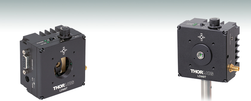
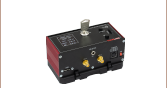
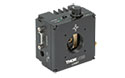
LDM9T
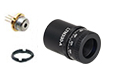
Application Idea
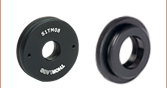
LDM9T with
S1TM09 Adapter
and C230TMD-C
Aspheric Lens


Please Wait
| Item # | LDM9Ta |
|---|---|
| Laser Diode Packageb | Ø5.6 mm and Ø9 mm |
| Supported Pin Configurationsc | A, B, C, D, E, G, and H |
| Maximum Laser Current | 200 mA |
| TEC Heating/Cooling Capacity | 0.5 W |
| Temperature Adjustment Range | 20 - 30 °C |
| TEC Control | 1 Turn Knob |
| Maximum TEC Current | 1 A |
| Laser Polarity Select | Internal Slide Switches |
| Temperature Sensor | 10 kΩ Thermistor |
| Front Mounting | SM1 (1.035"-40) Threaded Aperture and 30 mm Cage System Holes |
| Post Mounting Holes | 3 x 8-32 (M4 x 0.7) |
Features
- Compact Size: 3.09" x 2.89" x 1.79" (78.5 mm x 73.3 mm x 45.5 mm)
- Ø5.6 mm and Ø9 mm Laser Diode Operation
- Integrated Temperature Controller Included
- Compatible with Pin Codes A, B, C, D, E, G, and H (Diagrams Below)
- RF Modulation Port
- SM1 (1.035"-40) Thread and 30 mm Cage System Compatible
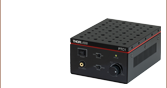
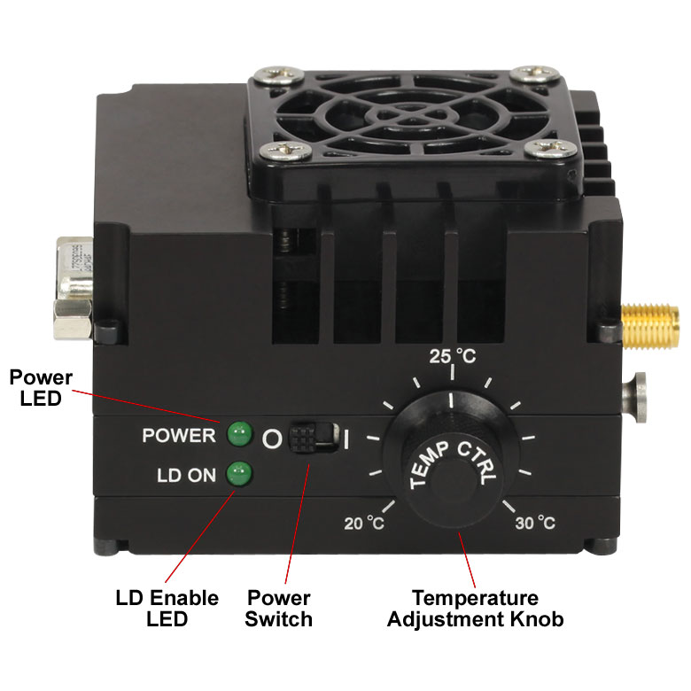
The LDM9T is a laser diode mount including an integrated thermo-electric cooler (TEC) and temperature controller to precisely regulate the operating temperature of a laser diode. By integrating the TEC the PID loop settings can be tuned specifically for this mount at the factory. Aided by an integrated low speed fan, the temperature range is approximately 20 to 30 °C. A TEC power supply is included with the LDM9T.
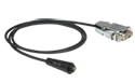
The LDM9T is directly compatible with Thorlabs' LDC Series controllers. A four pin socket accepts all Ø5.6 mm and Ø9 mm laser diodes. Easy to use polarity switches allow the laser mount to be configured for most laser pin assignments (see Pin Configurations tab). The front side of the mount has a standard SM1 (1.035"-40) lens tube thread and 30 mm cage system holes for collimating or focusing optics. The left side of the mount accepts a DB9 inputs from a laser current source.
A 50 Ohm RF input using a bias-tee allows the laser to be directly modulated to 1 GHz. Additional safety and protection features include on board reverse bias protection diodes, remote safety interlock connection, and the TEC Lockout circuit that prevents enabling of the laser diode unless the temperature controller is also enabled. Designed to work with our LDC controllers the TEC Lockout can easily be bypassed by setting an on-board jumper.
Mounting collimating and other optics is easy using standard Thorlabs optomech parts. Step by step procedures for mounting optics and controlling the laser diode are found in the manual and the Pin Configurations, Electronic Control and LD Collimation tabs above. Contact Tech Support for more information.
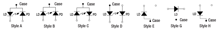 Supported Pin Configurations. Style G is supported with modifications to the LDM9T, see Pin Configurations tab.
| Laser Diode Accessory Selection Guide | |||||
|---|---|---|---|---|---|
| Other Temperature Controlled Mounts |
Passive Mounts | Passive Mounts with Collimation Package | Strain Relief Cables | Diode Sockets | Controllers |
 |
 |
 |
 |
 |
 |
| LDM9T Specifications | |
|---|---|
| Laser Diode Packagea | Ø5.6 mm & Ø9 mm |
| Supported Pin Configurations | A, B, C, D, E, G, and H (some modification necessary for G style)b |
| Laser Polarity Select | Internal Slide Switches |
| Laser Diode Current (Max) | 200 mA |
| Laser Diode Compliance Voltage | 7.5 V |
| Modulation Frequency | DC to 200 kHz |
| RF Modulation Frequency | 200 kHz to 1 GHz |
| Max RF Power | 250 mW, RMS |
| RF Input Impedance | 50 Ω |
| Max TEC Current | 1 A |
| TEC Heating/Cooling Capacity | 0.5 W (Tambient = 25 °C, TLD = 20 °C) |
| Temperature Adjustment Range | 20 - 30 °C |
| Temperature Stability | <0.02 °C (1 hour) <0.05 °C (24 hours) |
| Typical Settling Time | <2 min heating, <3 min cooling |
| Temperature Sensor | 10 kΩ Thermistor ±2% @ 25 °C |
| TEC Control | 1 Turn Knob (Potentiometer) |
| TEC Power Supplyc | Desktop Switching Supplyb |
| Supply Input | 100-240 VAC, 50-60 Hz |
| Supply Power | 12W |
| Supply Output Voltage | 5 VDC |
| Operating Temperature | 10 to 30 °C |
| Storage Temperature | -20 - 70 °C |
| Laser Interface | DB9, Female |
| Supply Connector | 2.5 mm Power Jack |
| RF Input Connector | SMA Jack |
| Interlock Concector | 2.5 mm Phono Jack |
| Indicators | LD Enabled Green LED, Power On Green LED |
| Size | 3.09" x 2.89" x 1.79" (78.5 mm x 73.3 mm x 45.5 mm) |
| Weight | 0.56 lbs (1.55 lbs ship weight) |
| Front Mounting | SM1 (1.035"-40) Threaded Aperture and 30 mm Cage System Holes |
| Post Mounting Threads | 3 x 8-32 (M4 x 0.7) |
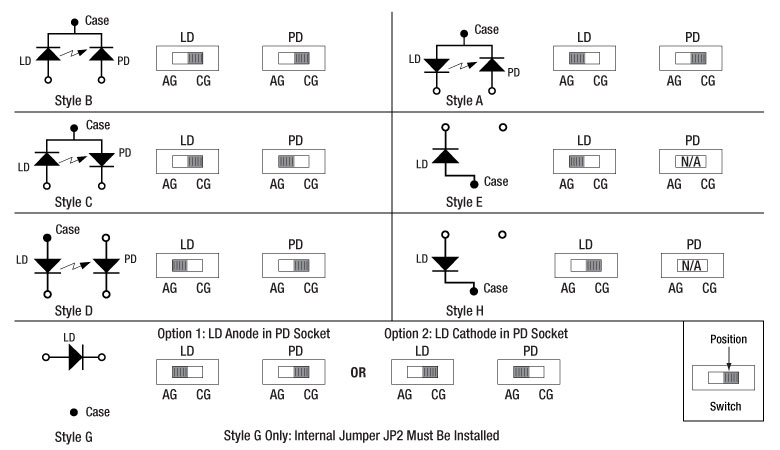
Figure 1: Supported and Unsupported Pin Configurations
*Style G is Supported with Modifications to the LDM9T, see below.
Laser Diode Pin Configurations
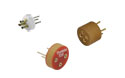
Thorlabs offers several different laser diodes in the UV, visible and IR. The electrical connections for these diodes vary based on the internal circuitry of the diode. Many of the laser diodes feature a built-in monitor photodiode. Use the descriptions and schematics below, along with the appropriate style pin code (A - F), to properly power the laser diode.
The LDM9T Laser Diode Mount is compatible with all Ø5.6 mm and Ø9 mm laser diodes with 3 pins in an A, B, or C style configuration as shown in figure 1. All three styles contain both a laser diode and a photodiode for monitoring. These configurations feature independent control of the Laser Diode (LD) and Photodiode (PD) voltages, along with a common Ground (G) pin.
In addition, the mount is compatible with all of our currently available 4-pin laser diodes with a style D configuration (see Fig. 2 to the right). As with style A, B, and C laser diodes, style D laser diodes feature a laser diode and monitoring photodiode; however, in contrast, style D contains two ground pins instead of only one. Please note that there is a difference between style D 4-pin and style F 4-pin (described below) configurations.
The LDM9T Mount is also compatible with style E and H laser diodes, which do not have a corresponding photodiode. These laser diodes only contain a laser diode and ground pin, as shown to the right in figure 1. The LDM9T is also compatible with style G laser diodes through the use of an internal jumper.
Please note: The LDM9T mount is NOT compatible with style F 4-pin configurations. The style F pin configuration, though similar to the style D configuration in that it contains four pins, has a pin layout that prohibits use in the LDM9T mount. For more information, see the sections below or contact tech support.
Figure 2. LDM9T Standard Configuration
LDM9T Mounting Configuration
The LDM9T Laser Diode Mount has a standard 4-pin LD and PD mounting configuration. Both LD and PD connections can be made according to the diagram in Figure 2. Please note the orientation of the laser diode configuration (top/bottom and front/back) as it may vary between manufacturers, product lines, and/or configurations. The pin numbering convention on the laser diode manuals may differ as well.
The configuration shown to the right allows direct mounting of style A, B, C, D, and E configurations without any alteration to the mount. Style G laser diodes require modification to the laser diode mount. Please see the next section for more details.
Style F laser diodes are incompatible with the LDM9T mount. The pin layout of the style F connectors place the LD and PD next to each other, instead of across from each other as shown in Figure 3 and described below in detail.
Click to Enlarge
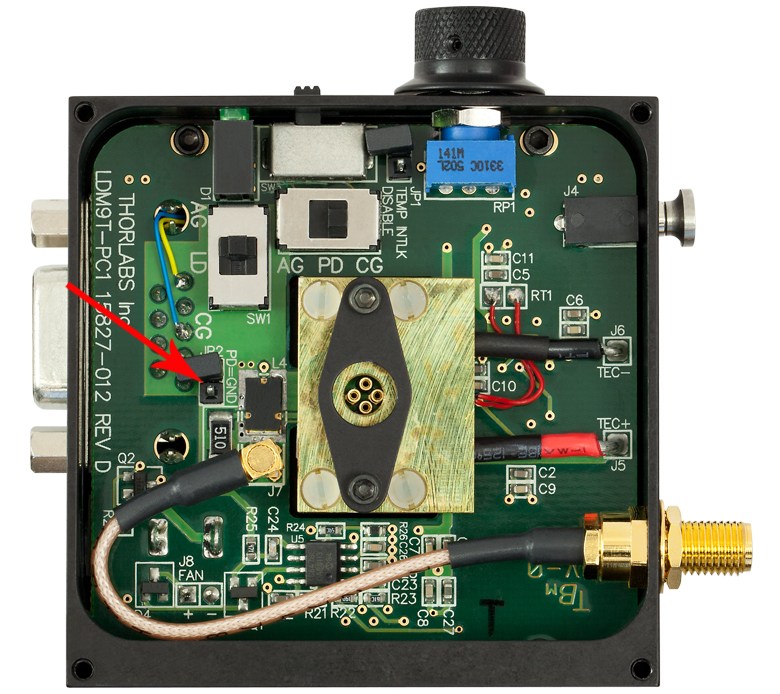
Figure 3: The JP2 Jumper, Shown with a Red Arrow in this Photo, Must be Shorted for use with G Pin Code Diodes
Style G Configuration
Style G configurations feature only a laser diode in the package; no photodiode is present. Since the LD and ground pins are directly across from each other (i.e,. in the LD and PD positions or 3 and 9 o'clock positions), the LDM9T requires an internal jumper for compatibility with style G laser diodes.
In order to drive a style G laser diode, the PD pin in the mount must be grounded. To ground the PD pin, remove the front cover to the LDM9T mount. Locate jumper J2 on the left-hand side of the mount, as shown in the photo to the right. Short the two pins together using the included jumper (the black plastic jumper should already be attached to one of the pins, as shown in the photo). Grounding the photodiode pin will allow the mount to drive a laser diode only (no photodiode) configuration with the LD pins at the 3 o'clock and 9 o'clock positions.
Note: In this configuration, the PD pin will be the ground pin. Proper mounting of the laser diode anode and cathode is required. In order to use the mount with any other laser diode style will require undoing the modification performed above.
Figure 4. Unsupported Style F Configuration
Incompatible Style F Configurations
The LDM9T is not compatible with any style F connections, even though the configuration is very similar to the D style configuration.
The HL6548FG 660 nm, 90 mW laser diode features a style F configuration. A schematic showing the internal circuitry of the laser diode is shown in Figure 4. The incompatibility stems from the the arrangement of the PD and LD pins. In style F connectors, the PD and LD pins are located diagonally from one another (9 and 12 o'clock positions, or any adjacent position). With this configuration, it is not possible to apply the correct voltage bias across both diodes simultaneously using the LDM9T laser diode mount.
For questions about compatibility of our style F laser diodes, or any other configuration, please contact tech support.
LD Driver
D-type Female
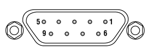
| Pin | Signal | Description |
|---|---|---|
| 1 | Interlock and Status Pin (LDC Specific) | This pin is the input to the LD Status and Interlock Circuits. When using Thorlabs LDCs no external circuitry is required. |
| 2 | Photodiode Cathode | This pin is connected to the 12 o'clock pin on the laser socket when the PD Polarity Switch is set to AG (anode ground). It is attached to ground and the 9 o'clock and 3 o'clock pins on the laser socket when the PD Polarity Switch is set to CG (cathode ground). |
| 3 | Laser Ground (Case) | This pin is connected to the 9 o'clock and 3 o'clock pins on the laser socket and corresponds to the settings of the LD and PD polarity switches. i.e. If the LD and PD switches are set to AG then this pin grounds the Anodes of the laser and photo diodes. |
| 4 | Photodiode Anode | This pin is connected to the 12 o'clock pin on the laser socket when the PD Polarity Switch is set to CG (cathode ground). It is attached to ground and the 9 o'clock and 3 o'clock pins on the laser socket when the PD Polarity Switch is set to AG(anode ground). |
| 5 | Interlock and Status Return | This pin is the return side of the Interlock circuitry. |
| 6, 9 | N.C. | These pins are typically used to monitor LD voltage when used with the Thorlabs LDC series controllers. This mount does not support this feature. |
| 7 | Laser Diode Cathode | This pin is connected to the 6 o'clock pin on the laser socket when the LD Polarity Switch is set to AG (anode ground) . Otherwise it is floating. |
| 8 | Laser Diode Anode | This pin is connected to the 6 o'clock pin on the laser socket when the LD Polarity Switch is set to CG (cathode ground) . Otherwise it is floating. |
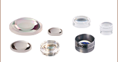
Choosing Collimation and Ellipticity Correction Optics for Your Laser Diode
Since the output of a laser diode is highly divergent, collimating optics are often necessary. Due to their excellent ability to correct spherical aberration, aspheric lenses are the most commonly used optics when the desired collimated beam waist is between one and five millimeters. Choosing an appropriate aspheric lens for collimating a laser diode is essential, as the resulting beam size and transmission range are dependent on the lens used. To calculate the beam size of a collimated laser diode, we first need to know its divergences.
The beam divergences of an edge-emitting laser diode will be different in the parallel and perpendicular directions, leading to an elliptical beam. This can be compensated for by inserting anamorphic prism pairs or cylindrical lenses into the collimated beam. The divergences are typically specified as "Beam Divergence (FWHM) - Parallel" and "Beam Divergence (FWHM) - Perpendicular" for the two axes of the chip. There are variations from lot to lot of laser diodes, but using the typical divergence values should be adequate for most applications.
The simple example below will illustrate the key specifications to consider when choosing the correct optics for a given application.
Example: 785 nm, 25 mW Laser Diode, L785P25, Ø3 mm Desired Collimated
Step 1: Collimating Emission
The specifications for the L785P25 laser diode indicate that the typical perpendicular and parallel beam divergences are 30o and 8o, respectively. The major (perpendicular) beam divergence is shown in Figure 1. The minor (parallel) beam divergence is shown in Figure 2. Because of this asymmetry in the two axes, an elliptical beam will form as the light diverges. To collect as much light as possible during the collimation process, consider the larger of these two divergence angles in any calculations (i.e., in this case use 30o).
Note: Parallel and perpendicular notation are specified relative to the junction plane of the laser diode.
Figure 1. Perpendicular beam divergence from L785P25 style B laser diode
Figure 2. Parallel beam divergence from L785P25 style B laser diode
In the above schematics, LD denotes the laser diode,  and
and  are the beam diameters in the parallel and perpendicular orientations, respectively, and
  and
and  are the divergence angles in the parallel and perpendicular orientations, respectively. Please note that the notch in Figures 1 and 2 can be used to determine the orientation of the laser diode within the package. Laser diodes are typically oriented parallel to the notch; however there are many exceptions, especially for different laser diode packages. Care should be taken to note the orientation of the laser diode emission.
To calculate the focal length needed to achieve a Ø3 mm collimated beam diameter, we can use:
where  is the focal length that produces the desired perpendicular beam diameter, . The focal length of the lens needed to collimate a 30o diverging beam into a Ø3 mm collimated beam is = 5.6 mm.
This equation yields the focal length to achieve our desired major (perpendicular) axis diameter. Use this to then select an aspheric lens with a focal length that most closely matches the focal length given by the equation. Please note that the diameter of the lens must be larger than your desired major axis beam diameter.
Thorlabs offers a large selection of aspheric lenses. For this application, the ideal lens is an -B AR-coated molded glass aspheric lens with focal length near 5.6 mm. The C171TMD-B (mounted) or 354171-B (unmounted) aspheric lenses have a focal length of 6.20 mm. Next, check to see if the numerical aperture (NA) of the diode is smaller than the NA of the lenses so that the light emitted from the laser diode is not clipped by the lens:
0.30 = NALens > NADiode ~ sin(15) = 0.26
Figure 3. Anamorphic Prism Pair and optic trace for an ellipse to round beam.
Solving the first equation again with your actual focal length and major axis divergence angle yields the actual major axis beam diameter, = 3.3 mm.
Step 2: Correcting Ellipticity
Emission from an edge emitting laser diode is elliptical (asymmetric with respect to two different axes), as shown in Figures 1 and 2. To correct for this and produce a circular beam, the minor axis diameter, , can be magnified using anamorphic prism pairs or cylindrical lenses after collimation. Note: only cylindrical lens pairs can correct for any astigmatism present in the diode output. Figure 3 shows an anamorphic prism pair magnifying an elliptical beam minor axis to produce the desired symmetric beam.
To determine what magnification of the minor axis is needed to produce a round beam, solve Eq. 1 using the focal length from the aspheric lens,![]() = 6.20 mm, = 8o, instead of the major axis divergence. This results in a minor axis diameter, = 0.9 mm. Comparing and , we see that a 3.5X magnification is necessary in the minor beam axis. This 3.5X magnification can be achieived using the PS881-B Mounted Anamorphic Prism Pair.
= 6.20 mm, = 8o, instead of the major axis divergence. This results in a minor axis diameter, = 0.9 mm. Comparing and , we see that a 3.5X magnification is necessary in the minor beam axis. This 3.5X magnification can be achieived using the PS881-B Mounted Anamorphic Prism Pair.
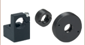
Lens Tube Mounting
For mounted aspheric lenses, our SM05Txx or S1TMxx adapters can be used. Take care to ensure that the lens does not contact the laser diode. The SM05Txx adapters will require the use of an SM1A6T SM1-to-SM05 adapter.
Unmounted aspheres can be epoxied to an LMRAxx adapter, which can then be mounted in an SM1A6T SM1-to-SM05 adapter. The SM1 threading of the adapter can then be used to attach the lens/mount/adapter to the laser diode mount's front plate. The SM1A6T adapter has a mounting range of 10 mm, covering almost the entire focal length range of our aspheric lenses.
In the above example, the C171TMD-B mounted lens features M8 x 0.5 threading, thus requiring the S05TM08-threaded adapter. The S05TM08 M8-to-SM05 adapter can be mounted in the laser diode mount using the SM1A6T SM- to-SM05 adapter. The correct distance between the laser diode and lens can be achieved by adjusting both the S05TM08 and the SM1A6T adapters.
If the 354171-B, unmounted ashperic lens is used, it must first be epoxied to the LMRA5 adapter. It can then be mounted in the SM1A6T SM1-to-SM05 adapter. Again, adjustment of the aspheric lens can be made at the LMRA5 and SM1A6T adapters.
Cage Assembly Mounting
Mounted and unmounted aspheric lenses with focal lengths greater than 8 mm can be cage mounted using our 30 mm cage system. Cage rods can be attached directly to the front plate of the laser diode mount. The CP33(/M) cage plate may be used to hold the S1TMxx adapter with mounted aspheric lens or the SM1A6T adapter with unmounted aspheric lens epoxied to an LMRAxx adapter.
For larger translational adjustments, the CT1A(/M) 1/2" Travel Translator can be used. The CT1A(/M) translator has a graduated micrometer which provides 1/2" (13 mm) of linear translation and has 0.001" (10 µm) graduations. The smallest incremental movement of the carriage is approximately 1 µm.
Anamorphic Prism Pair Mounting
The asymmetric output of the laser diode can be corrected using either anamorphic prisms or cylindrical lenses. As determined in the example above, a 3.5X mounted anamorphic prism pair (i.e., PS881-B) was needed to produce a round beam profile. Unmounted prisms may be used as well.
The PS881-B Mounted Anamorphic Prism Pair features SM05 threading on the output end or may be mounted inside an SM1 Lens tube. Since the input and output beams from the Anamorphic Prism Pair are offset from each other, prisms should be mounted on another cage or lens tube axis.
Electronic Assembly and Control
This guide will serve as an overview of the LDM9T electronic assembly and operation, as well as provide options for powering the laser diode and temperature controller. Full details of the assembly and operation of the LDM9T Mount can be found in the operating manual. The LDM9T can drive most laser diodes requiring a drive current up to 200 mA. A 50 Ω radio frequency (RF) input using a bias-tee allows direct modulation of the laser diode up to 1 GHz. The mount also provides an integrated thermoelectric cooler (TEC) and controller with 0.5 W of cooling power.
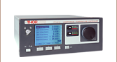
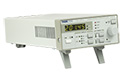
Laser Diode Controllers
Thorlabs offers a wide variety of laser diode controllers ranging from low power (low current and low voltage) to high power (high current and/or voltage) versions. Thorlabs also offers several dual laser diode current/temperature controllers and kits. Laser diode current controllers should be chosen based on the actual laser diode used and the particular application.
Thorlabs' LDC2xxC series of controllers are suitable for use with a large majority of popular laser diodes. Thorlabs' LDC200CV is specifically designed to handle and safely operate Vertical Cavity Surface Emitting Lasers (VCSELs), while the LDC201CU provides users with an ultra-low noise current (<0.2 μA RMS) for stable operation of low power laser diodes. If your application requires the higher voltages typically necessary for driving blue and other short laser diodes, consider our LDC202C, LDC205C, or LDC210C controller. For driving higher power laser diodes, the LDC220C and LDC240C offer drive currents of 2 A and 4 A, respectively. Higher current (5 and 20 A) and rack mount controllers are also available. All of these controllers operate in a similar manor. Only the LDC2xxC series controllers will be discussed in more detail..
Prior to installing a laser diode in the mount, the pin configuration style must be determined and the mount properly configured to power the diode. There are two switches located on the top of the mount that control the polarity of the laser diode and monitor photodiode, if present.
Click to Enlarge
Figure 1. Laser Diode and Photodiode Polarity Switch Settings.
There are four pin configurations (A, B, C, and D), which are completely compatible with the LDM9T mount. The four pin styles are shown in Figure 1 along with the electronic schematic and switch settings. In these configurations, the laser diode houses a monitor photodiode tied to either the cathode or anode ground of the laser diode.
A fifth configuration, Style E, may be directly compatible with the mount or may require modification to the mount depending on the orientation of the laser diode pins. These laser diodes do not have a monitor photodiode, and therefore, the mount may be altered to accommodate some style E pin layouts. See the Pin Configurations tab for more information on Style E compatibility and necessary modifications to the mount.
Style F laser diodes are not compatible with the LDM9T mount. These laser diodes also feature a monitor photodiode; however, the pin layout prohibits the mount from powering the laser diode and photodiode simultaneously. Please see the Pin Configurations tab for more information.
Once the pin configuration is set, the controller can be connected to the mount via the DB9 male cable. The LDC2xxC series of controllers is preconfigured to interface directly with the mount. If a third-party controller is used, see the laser diode connector pin configuration in the operating manual to determine the proper connections.
RF Modulation
Modulation of a laser diode is possible but not via the laser diode controller. The input from the laser diode controller is sent through an inductor that only allows low bandwidth, DC currents to pass through to the laser diode. To allow high frequency modulation of the laser diode, the mount's built-in bypass needs to be used to circumvent the low pass filter. The bypass is accessed through an SMA connector on the side of the mount, is directly coupled to the laser using a bias-tee network, and features a 50 Ω RF input that can accept an AC-coupled RF source up to 1 GHz.
In order to properly modulate the laser diode emission, the correct modulation voltage must first be determined. The modulation voltage is determined from the laser diode modulation current and the input impedance:
VRF = ILD * Zinput. (1)
Here, VRF is the modulation voltage, ILD is the LD modulation current determined from the manufacturer, and Zinput is the impedance of the mount, which is equal to 50 Ω.
When setting the modulation voltage, it is recommended to start at a factor of 10 lower than the value determined from Eq. 1. The modulation voltage can then be slowly increased until VRF or the desired modulation is achieved. The laser diode controller can then be used to increase DC voltage to the proper level.
Warning: The RF input is directly coupled to the laser diode. There is no suppression of noise or other spurious signals to the laser diode. Stable and clean RF sources should be used to avoid overdriving the laser diode. In addition, the laser diode can be easily overdriven by an RF voltage above the specified level in Eq. 1. Take care when controlling and adjusting the RF voltage to avoid damage to the laser diode.
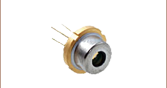
Video Insight: Setting Up a TO Can Laser Diode
Installing a TO can laser diode in a mount and setting it up to run under temperature and current control presents many opportunities to make a mistake that could damage or destroy the laser. This step-by-step guide includes tips for keeping humans and laser diodes safe from harm.
If you would like more information about tips, tricks, and other methods we often use in the lab, we recommend our other Video Insights. In addition, our webinars provide practical and theoretical introductions to our different products.
| Posted Comments: | |
user
(posted 2023-03-09 13:49:09.663) Hi,
I would like to know if this mount is compatible with this diode, and otherwise which 532nm diode it's compatible with, as we currently have a blue diode that we want to switch out for green.
https://www.thorlabs.com/thorproduct.cfm?partnumber=DJ532-40
We are currently controlling it with one of the Kinesis drivers. https://www.thorlabs.com/newgrouppage9.cfm?objectgroup_ID=3355
Best wishes,
Simone Eizagirre ksosnowski
(posted 2023-03-10 09:52:07.0) Thanks for reaching out to Thorlabs. For DJ532 laser diodes we recommend the LDM56 mount with LDM56DJ adapter flange. Unfortunately we have not designed a similar flange for the LDM9T(/M) mounts. While DJ532 should fit, it would not have the intended thermal contact if used in LDM9T, which can effect the efficiency of the nonlinear optic inside this laser. Additionally LDM9T would limit the laser current to 200mA which could limit the max power on the DJ532 diodes. KLD101 also has a 230mA current limit, which can drive the typical max rating for DJ532-10, but won't reach the max for DJ532-40 which typically requires 330mA. As temperature control is recommended, I would suggest checking out our LTC56A laser driver kit which you can use as a basis for a setup on this diode. DJ532-10 and -40 in particular have internal optics so may not require extra collimating lenses from those kits. Junhyeok Hur
(posted 2022-06-22 11:00:43.933) Dear Thorlabs
I wonder about the safety consideration of this LD mount.
We are trying to use it with the Laser diode which is very sensitive to spike noise.
The supplier of LD recommends using a 10uF capacitor parallel to the LD.
I want to check the internal circuitry of LDM9T/M to see whether it has safety features such as a Low Pass filter or not. ksosnowski
(posted 2022-06-23 06:16:30.0) Thanks for reaching out to Thorlabs. The LDM9T(/M) units have integrated reverse bias protection, but not any protection for overvoltage/voltage spikes/ESD. Generally speaking, including a capacitor like this as a lowpass filter would also serve to limit the modulation bandwidth of the device at the same time. You may be able to integrate this yourself, though the extra capacitance would increase the rise and fall times of any diode installed. It is possible to use one of our inline electrical housings to put one on the RF Modulation port but again this would reduce the bandwidth to the cutoff frequency of the filter used. Rafael Rojas
(posted 2021-10-11 06:00:25.483) I would like to ask about the compatibility of the LDM9T/M and the DPSS laser (DJ532). Is it possible to use them together? Do I need any aditional adapter or sugestion for its use? YLohia
(posted 2021-10-11 02:18:53.0) Thank you for contacting Thorlabs. Unfortunately, the LDM9T is not compatible with the DJ532 laser since that laser features a non-standard 9.5 mm packaging which requires the LDM56DJ flange. The flange is not compatible with this mount. We suggest using the LDM56 instead. wenzel.jakob
(posted 2017-11-27 10:36:09.237) Is the LDM9T compatible with the T-Cube current controller (TLD001)? If so, are there disadvantages relative to the more expensive LDC202C? nbayconich
(posted 2018-01-09 02:23:42.0) Thank you for contacting Thorlabs. The LDM9T is compatible with the T-cube controller TLD001. The advantage to using the LDC202C controllers is that they will have a higher compliance voltage and higher modulation frequency bandwidth. The advantage to having the TLD001 is that it can be controlled through graphical software by using either APT or kinesis. bradley.hallock
(posted 2013-04-25 21:09:23.45) The pin sockets have no funnels to guide the pin into the socket making it very challenging to seat the TO can. Inserting a TO can into most sockets is fairly easy; this mount has the worst socket I have ever used. Now I'm trying to figure out how to modify this mount to make it useful and to meet my project deadline.
The clamp doesn't allow very quick mounting/dismounting of the TO Can as well. tcohen
(posted 2013-05-02 14:35:00.0) Response from Tim at Thorlabs: Thank you for your feedback. We will look into adding sockets to improve the ease of mounting. Because of the variety of diode pin spacings we must ensure that any funnels put within the cold plate through hole will open wide enough at the top to ensure the diode pins are separated far enough from the can as to prevent damage. We will look into the options to make this more convenient to mount into and I will contact you to continue this discussion. |
| Laser Diode Mount Selection Guide | |||||||
|---|---|---|---|---|---|---|---|
| Item # | LDM38(/M) | LDM56(/M) | LDM56F(/M) | LDM90(/M) | LDM21 | LDM9T(/M) | |
| Click Photo to Enlarge | 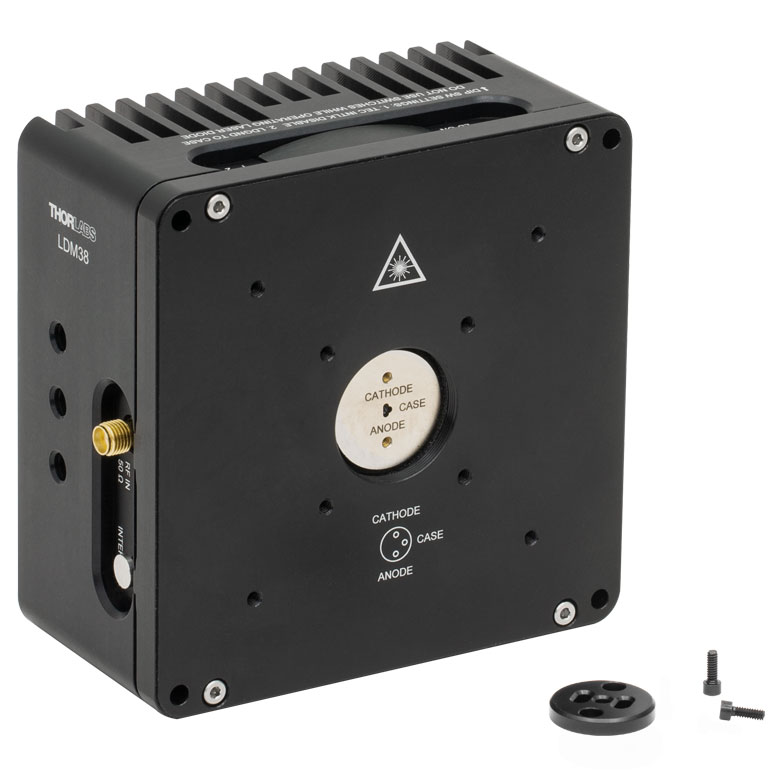 |
 |
 |
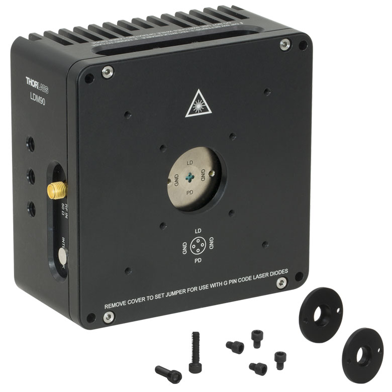 |
 |
 |
|
| Laser Diode | |||||||
| Supported Laser Diode Package(s) | Ø3.8 mm | Ø5.6 mm | Ø5.6 mm | Ø9 mm | Ø5.6 mm and Ø9 mm | Ø5.6 mm and Ø9 mm | |
| Supported Pin Configuration(s) | G | A, B, C, D, E, Ga, H (Switch Selectable) |
F and G (Switch Selectable) |
A, B, C, D, E, Ga, H (Switch Selectable) |
A, B, C, D, E, and H | A, B, C, D, E, G, and H (Some Modification Necessary for G Style)b |
|
| Maximum Laser Current (Tambient = 25 °C) |
1 A | 2 A | 500 mA | 200 mA | |||
| RF Modulation Frequency Rangec | 100 kHz to 500 MHz | 100 kHz to 600 MHz | N/A | 200 kHz to 1 GHz | |||
| Temperature Controller | |||||||
| TEC Heating/Cooling Capacity (Tambient = 25 °C) |
8 W | 8 W | 2 W | 0.5 W | |||
| Temperature Adjustment Range | - | 0 to 70 °C | 20 to 30 °C | ||||
| General Specifications | |||||||
| Laser Interface | DB9 Female | ||||||
| TEC Interface | DB9 Male | N/Ad | |||||
| Compatible Current and Temperature Controllers | LDC Series and T-Cube LD Controllerse, ITC Series Combined LD/TEC Controllersf, and Temperature Controllersf | LDC Series and T-Cube LD Series Controllerse |
|||||
| Mounting Features | Imperial Mounts | 1/4"-20 Tapped Hole (9 Places) | 8-32 Tapped Holeg (4 Places) |
8-32 Tapped Hole (3 Places) |
|||
| Metric Mounts | M6 x 1.0 Tapped Hole (9 Places) | N/A | M4 x 0.7 Tapped Hole (3 Places) |
||||
| Accommodations for Collimating Optics | SM1 (1.035"-40) Series Internal Thread; LDMXY Flexure Adapter (Sold Separately) |
SM1 (1.035"-40) Series Internal Thread | |||||
| Cage System Compatibility | 4-40 Tap (8 Places) for 30 mm and 60 mm Cage Systems |
4-40 Tap (4 Places) for 30 mm Cage System | |||||
| Dimensions | 4.00" x 4.00" x 2.07" (101.6 x 101.6 x 52.6 mm) |
1.75" x 1.75" x 1.66" (44.5 x 44.5 x 42.1 mm) |
3.09" x 2.89" x 1.79" (78.5 x 73.3 x 45.5 mm) |
||||