 Products Home
Laser Diode Tutorial

Please Wait
| Selection Guide |
|---|
| Laser Diodes by Wavelength |
| Laser Diodes by Package & Type |
| Drivers & Mounts |
Laser Diode Tutorial
The purpose of this laser diode tutorial is to provide the information necessary to create a long lifetime, stable laser diode system. Much of what will be discussed will be in general terms of laser diode performance, warnings, and tips. Much of the specifics are left to the user as any system can vary significantly from lab to lab or application to application. However, the guidelines and tips outlined in this tutorial will supply the information necessary to plan a proper system that will supply stable operation over long diode lifetimes.
The general strategy in constructing a laser diode system is similar for all such systems. Application is going to define the major parameters of a laser diode: wavelength, power, and package style. Once known, the next set of choices revolves around mounting a laser diode and choosing the appropriate drivers, regulators, and choosing the placement of the diode within the lab. As we will see through this tutorial, there are many things to keep in mind when planning out a laser diode system. It may seem daunting at first and riddled with considerations that may not have seemed important. But through proper planning, handling, equipment, and precaution a laser diode can supply stable, consistent performance for 100,000’s of operating hours.
Laser Diode Types
This tab takes us through an introduction to the various types of semiconductor diode lasers. Background information on the semiconductor structure, lasing type, integrated feedback, etc. is laid out here. In most applications laser type will be decided by application, and as such this tab provides a general background about diodes and serves as information for the interested reader.
LD Guide
In the LD Guide tab, we will walkthrough an overview of the major considerations and warnings involved with handling and operating laser diodes. Damage mechanisms are introduced and common methods and tips on how to avoid damaging your laser through these mechanisms are laid out. Other helpful tips such as the important parameters listed in a specs table and diode packages are discussed. Furthermore, we introduce some of the basics for laser diode mounts and drivers, including desired and necessary features of a proper laser diode controller
Mounting LDs
We present here a more in depth look at mounting laser diodes. What type of mounts are really necessary, which ones are desired, what you'd like to look for in a mount, etc. Mounting lasers doesn't end at the diode mount itself, and thus this tab also discusses common tips and practices when planning out your laboratory environment for optimal placement of diode systems. The life of a laser diode can be fraught with danger, and where you place it on your table can affect the risk of catastrophic failure to the diode.
The information contained within this tutorial will give all the general information necessary to create an excellent laser diode system. For specific questions about laser diodes, mounts, and drivers please contact Tech Support.
Semiconductor Lasers
Semiconductor lasers are comprised of a large group of binary, ternary, and quaternary elements from Groups III -VI from the periodic table. These lasers can have emission ranges from the blue (~400 nm) to the IR by combining elements from Groups III and V or Groups IV and VI, respectively. This large emission range combined with the small device footprint, low operating current, low operating cost, and high efficiency makes semiconductor lasers one of the most important and widely used classes of lasers in use today. Please see our Lasers page for a complete listing of all laser diodes offered by Thorlabs. For applications requiring diodes not listed on our Coherent Sources page, please contact Tech Support.
Fabry-Perot Laser Diodes
The simplest type of semiconductor laser is the Fabry-Perot (FP) laser diode. In this device, two parallel ends of the semiconductor are cleaved along the crystal axis, creating reflective mirrors forming a Fabry-Perot laser cavity with the semiconductor as the gain medium. Optical coatings are typically applied to the mirror facets to optimize the output power, with the laser emission taken from the low-reflectivity front facet and high-reflectance on the back facet to reduce the overall mirror loss. The gain spectrum of the semiconductor medium is quite broad and supports lasing over many longitudinal modes of the FP cavity. Consequently, FP laser diodes typically operate with multiple longitudinal modes.
For FP laser diodes that are fabricated such that the optical beam is confined in an optical waveguide with a single-transverse mode (which is also called “single-spatial mode,” but commonly just shortened to “single mode”), the longitudinal mode spacing is determined by Δv = c/2nL, where c is the speed of light, L is the laser diode chip length, and n is the group index of refraction of the semiconductor waveguide. It is often more convenient to express the mode spacing in terms of wavelength (Δλ = λ2 /2nL), which is more readily measured directly on an optical spectrum analyzer.
For example, taking typical values for the group index of refraction n = 3.5 and cavity length L = 1 mm, yields longitudinal mode spacing of Δλ = 0.05 nm @ 635 nm and Δλ = 0.3 nm @ 1550 nm. The number of lasing longitudinal modes and the ratio of the power in the various modes, which is characterized by the side-mode-suppression ratio (SMSR), is influenced strongly by the type of material used to form the semiconductor gain medium (AlGaAs, InGaAsP, AlGaInP, etc.) as well as the bias current and temperature. For GaAs-based FP lasers, it is often possible to adjust the bias current/temperature such that single-longitudinal mode operation can be achieved with an SMSR of 5-10 dB over a limited current/temperature operating range. In order to obtain more stable single-longitudinal mode operation with high SMSR (>30 dB) and narrow linewidth (<10 MHz), other types of laser diodes such Distributed Feedback (DFB), Distributed Bragg Reflector (DBR), and Vertical Cavity Surface Emitting Lasers (VCSEL) should be used. These type of semiconductor lasers will be discussed below.
In general, the output power and wavelength that a laser diode displays is tunable by altering the temperature and/or current. This is extremely evident with IR laser diodes where small changes in temperature greatly affect the small band gaps. Thus almost all laser diodes are temperature tunable, though this tunability is generally small (~10s of nm). Laser diodes also display some current-based power tunability. Increasing the input current increases stimulated emission up to a specified value; however above that value, spontaneous emission starts to compete with the stimulated emission process. It is thus recommended to keep input currents within the specified range for each laser diode.
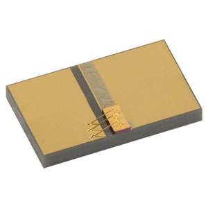
Figure 1. FP chip on submount laser diode
The polarization of the stimulated emission is generated parallel to the junction plane while spontaneous emission is unpolarized. For high polarization efficiency (50:1 or greater), it is also recommended to keep the input current within the specified range.
The first FP laser diodes utilized a single semiconductor material, predominantly GaAs, to form a single p -n junction diode. These devices were subsequently labeled homojunction laser diodes.1-4 While these early FP lasers demonstrated the principles of the laser diode, cryogenic temperatures were necessary for cw operation to prevent destruction due to the high current density threshold, Jth≈ 105 A/cm2, inherent to these devices. The advent of the heterostructure laser diode several years later reduced the high threshold current density and allowed the development of a wide range of room temperature FP laser diodes.
Figure 1 shows a FP chip on submount laser diode. The chip has two welded gold contacts to the n- and p- doped semiconductor layers. This chip, FPL2000C, is manufactured to form a FP laser cavity tuned to emit 30 mW of CW light at 2000 nm. The FP laser cavity yields a spectral bandwidth of ~15 nm (nom.). This diode features a quantum well structure, which is described below.
Thorlabs' offers several different types of FP laser diodes. Packaged FP laser diodes can be found for the Visible and IR. We also offer butterfly, chip on submount, and C-Mount packaged versions to complete our LD product line. For other FP laser diode options please contact Tech Support.
Heterostructure Laser Diodes
Heterostructure arrangements allowed the widespread development of room temperature cw operation laser diodes. Single Heterostructure (SH) arrangements were first developed, followed quickly thereafter by the Double Heterostructure (DH) laser diode. The DH laser diode is one of the most commonly used laser diodes today. Briefly, DH laser diodes feature low threshold current densities, room temperature operation, and high efficiency.
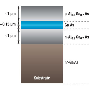
Figure 2. DH laser diode structure
Double Heterostructure laser diodes are comprised of a thin, active region (100 - 200 nm), surrounded by two thicker (1 - 2 μm) cladding layers, which form the p - n junction. Figure 2 shows a typical DH laser diode structure. In this example, the GaAs active area is 0.15 μm thick with 1 μm cladding layers of p-Al0.3Ga0.7As andn-Al0.3Ga0.7As. This structure is mounted to a thick GaAs substrate. The configuration reduces Jth ≈ 1 - 3 kA/cm2 and increases efficiency compared to the single junction laser diodes due to
- Photon confinement in the GaAs active region due to the larger index of refraction of GaAs (n = 3.6) compared to the p- and n- cladding layers (n = 3.4).
- Carrier confinement in the GaAs active region due to the smaller band gap (Eg ≈ 1.5 eV) of the GaAs compared to the p- and n- cladding layers (Eg ≈ 1.8 eV).
- Reduction in photon absorption arising from the differences in band gap of the active and cladding layers. Only photons created with energy equal to or greater than the larger band gap cladding layer are absorbed. This results in only minor absorption at the blue tail of the emission profile.
There are several limitations to the DH laser diode that affect wavelength ranges and device performance. The largest drawback to the DH laser diode is the strict lattice matching condition. Lattice mismatches greater than 0.1% can result in interfacial strain between the active and cladding layers, producing non-radiative electron hole recombination. The lattice matching restriction reduces the number of elements that can be used in the active and cladding regions, resulting in a decrease in possible wavelength ranges and increase in Jth .
Thorlabs offers a variety of DH laser diodes in the visible and NIR.
Quantum Well Laser Diodes
Quantum Well (QW) laser diodes are a special class of DH laser diodes where the active area thickness, D, approaches the de Broglie wavelength.
There are many benefits of using QW structures over the DH, or bulk, structures. Only the most important results are discussed here. The reader is directed to Reference 5 and the references therein for further information on QW vs. bulk optical properties. QW structures benefit from a large increase in differential gain compared to standard bulk DH structures. In addition, this gain is less affected by changes in temperature compared to the analogous bulk structure.
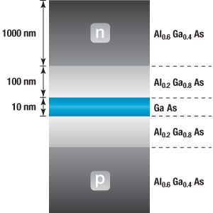
Figure 3. QW laser diode structure
A sample QW structure is shown on the left in Figure 3. The QW is comprised of a 10 nm thick GaAs active area surrounded by two confinement layers of Al0.2Ga0.8As, each with a thickness 100 nm. Surrounding the confinement layers are two thick, 1 μm layers of a high-band-gap, low-refractive-index material, Al0.6Ga0.4As.
This configuration features threshold current densities that are 4 - 5 time smaller than comparable DH heterostructures (Jth ≈ 100 - 300 A/cm2). A reduction in thickness is achieved and photon confinement is increased due to the particular outer cladding/confinement structure utilized. In addition, QWs show an improvement in device performance due to the increase in gain compared to bulk structures.
Quantum Well structures also reduce the strict lattice matching parameters found in DH structures. For very thin QWs, the mismatch in the lattice structure may be 1 - 3%. QW laser diodes with large interfacial lattice differences can operate without the boundary mismatch problems associated with DH laser diodes (non-radiative electron-hole recombination). These types of QWs are typically deemed Strained QWs (SQWs) and have opened up new wavelength ranges previously unavailable to DH laser diodes. These SQWs also improve the absorption characteristics, efficiency, and threshold current density compared to unstrained QWs. Further information on SQWs is available in Reference 5.
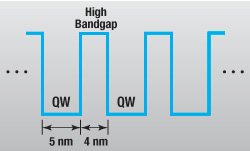
Figure 4. MQW energy diagram
QW structures may be laid out singly between two high band gap materials or in a series arrangement with alternating QW (narrow band gap) / barrier (high band gap) materials. This latter arrangement is termed the Multiple Quantum Well (MQW) arrangement. A MQW structure is shown to the right in Figure 4. In this structure, a repeating unit of a 5 nm layer of low band gap and a 4 nm layer of high band gap is deposited between a p -n junction.
Varying the material composition of the QW or barrier, the layer or barrier thickness, or the number of QWs (e.g. Multi, ML725B8F) can change the emission characteristics of the MQW.6 The only restriction in a MQW arrangement is the high band gap material (thickness and band gap) must be sufficient to eliminate electron tunneling, which would greatly reduce device efficiency.
Thorlabs offers a variety of MQW laser diodes in the visible and NIR.
Distributed Feedback Laser Diode
The Distributed Feedback (DFB) laser diode incorporates a grating into one of the cladding layers surrounding the active layer of a DH laser diode. The diffraction grating etched (or deposited) provides much narrower laser line widths and high temperature stability compared to DH laser diodes. Reflections at the end facets are not necessary in DFB laser diodes since the diffraction grating selects the wavelengths that are present in the gain medium.
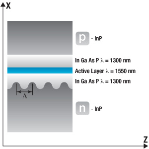
Figure 5. DFB laser diode structure
A DFB laser diode is shown to the right in Figure 5. The InGaAsP active layer, which has a band gap corresponding to emission at λ = 1550 nm, is surrounded by a cladding layer of InGaAsP, which has a slightly larger band gap corresponding to emission at λ = 1300 nm. One of the cladding layers has a varying thickness of period Λ. Each cladding layers is bordered on one side by a high band gap, low-refractive-index material (either p-InP orn-InP).
The variation in the cladding layer produces a refractive index along the z-direction, neff , that is dependent on the z location,
where the brackets refer to an average over the x-direction, orthogonal to the longitudinal axis. The transverse beam profile along the x-coordinate has a narrow width almost completely contained within the active area and cladding layers. We can impose a periodicity along the z-axis to the refractive index:
where n0 and n1 are the refractive indices of the cladding and substrate layers, Λ is the pitch of the periodic change in refractive index along the interface, and φ is the phase factor. Utilizing Bragg's Law from a grating or other periodic elements, forwards and backwards propagating beams are coupled if
where <neff > is the average refractive index along the z-axis. Under this simplified analysis, it is observed that only one wavelength can exist for a given pitch, Λ. A detailed analytical treatment beyond the simplified description here is available in References 7 and 8 and references therein. Thorlabs offers two DFB laser diodes operating at 1310 nm and 1550 nm. For other DFB laser diode needs please contact Tech Support.
Vertical-Cavity Surface Emitting Laser Diodes
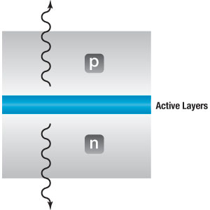
Figure 6. VCSEL energy diagram
Vertical-Cavity Surface Emission Laser (VCSEL) diodes are a unique class of laser diodes where the emission occurs perpendicular to the active layer/junction plane. This is in contrast to the previously described laser diodes, where the light propagation/amplification is parallel to the junction plane. VCSEL lasers are typically employed where low threshold currents, Jth ≈ 3 - 5 kA/cm2, and high emitter densities are required. The actual threshold currents (approximately a few milliamps) are much lower than FP laser diodes because of the small active area.
The short active area/gain medium limits scattering and absorption, improving efficiency. The short active area also allows VCSELs to typically operate in a TEM00 mode, even when high currents well above the threshold level are applied. VCSELs are not, however, recommended for high-power applications due to the vertical emission and short active area, which limits the gain length.
A VCSEL cavity is shown in Figure 6 to the right. Because the emission from these laser diodes is perpendicular to the junction plane, a high density of emitters can be produced over a small area. In addition, these devices can be configured for very high packaging density applications, as emitters can be very closely spaced compared to typical FP laser diodes.
The active area of a VCSEL is comprised of several strained QW layers, approximately 5 - 10 nm thick, utilizing a high band gap material of 4 - 6 nm thickness between the wells. Figure 7a shows the strained QW structures forming the active area of a VCSEL.
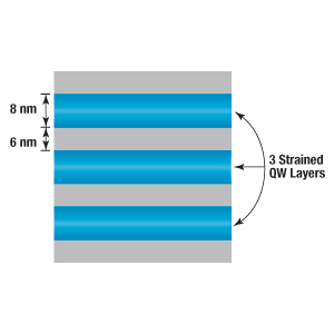
Figure 7a. The active area of a VCSEL

Figure 7b. The laser cavity of a VCSEL
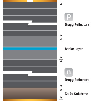
Figure 7c. The vertical structure of a VCSEL
The strained quantum wells, which are contained within two cladding layers, are shown in Figure 7b. These cladding layers make up the laser cavity of the VCSEL. The thickness of the laser cavity is approximately 1λ. VCSELs operating in the NIR (λ = 1-3 um) with similarly sized laser cavities have a mode spacing of Δλ ≈ 100 - 300 nm. This mode spacing allows single longitudinal mode emission at varying input currents.
The laser cavity is contained within a repeating structure of λ/4 thick high-refractive-index / low-refractive-index layers. This layering of many (on the order of 15 - 25) Bragg reflectors produces one mode with peak reflectivity at each of the quarter-wave stacks and is therefore amplified by the gain medium. Other modes present in the cavity are reduced by destructive interference from the λ/4 stacks. This vertical structure is shown in Figure 7c. The structure is anchored on a thick substrate and metal contact. The emission surface features a λ/2 thick layer (for phase matching) and metal contact with a circular aperture of approximately 5 - 10 μm.
Thorlabs' offers several packaged VCSELs in the NIR. For VCSEL solutions at other wavelengths please contact Tech Support.
1 Hall, R.N., Fenner, G.E., Kinhsley, J.D., Dills, F.H., Lasher, G., Coherent Light Emission from GaAs Junctions,Phys. Rev. Lett. 9, 366 (1962).
2 Nathan, M.I., Dumke, W.P., Burns, G., Dills, F.H., Lasher, G., Simulated Emission of Radiation from GaAsp-n Junctions, Appl. Phys. Lett.1, 62 (1962).
3 Holonyak, Jr., N. and Bevacqua, S.F., Coherent (Visible) Light Emission from Ga(As1-xPx) Junctions, Appl. Phys. Lett. 1, 82 (1962).
4 Quist, T.M., Keyes, R.J., Krag, W.E., Lax, B., McWhorter, A.L., Rediker, R.H., Zeiger, H.J., Semiconductor Maser of GaAs, Appl. Phys. Lett. 1, 91 (1962).
5 Svelto, O. and Hanna, D.C., Principles of Lasers, 4th ed., Plenum Press, New York (1998).
6 Kittel, C., Introduction to Solid-State Physics, 6th ed., Wiley, New York (1986).
7 Kogelnik, H. and Shank, C.V., Stimulated Emission in a Periodic Structure, Appl. Phys. Lett. 18, 152 (1971).
8 Otsuka, K., Winner-Takes-All and Antiphase States in Multimode Lasers, Phys. Rev. Lett. 67, 1090 (1991).
Laser diodes can provide stable frequency and power operation over long life times, but creating a system that can realize this operation is not trivial. Diodes can be easily damaged, running them hot can decrease life time, and various environmental conditions can cause catastrophic diode failure. This tutorial will address some of the basics for laser diode handling and operation that should be kept in mind when creating a laser diode system. We shall discuss below: damage mechanisms, specifications, diode packages, mounts and drivers, and some general tips on common laboratory phenomenon that can lead to diode instability or damage.
Section 1: Damage Mechanisms
When using a laser diode, it is important to know the various ways through which it may be damaged. Proper care is necessary when handling and using diodes in order to ensure consistent, reliable, and long lifetime operation. In particular laser diodes are susceptible to damage from electronic, thermal, and power mechanisms. We discuss below some of the common damage mechanisms involved with laser diode operation.
Electronic Mechanisms
Damage from electronic mechanisms is the number one reason for catastrophic laser diode failure. Of these, the most widely known is static discharge. Small electric charge can built up on a person as they shuffle around a lab or interact with various pieces of equipment. If not properly protected, this can cause an electrostatic discharge to the diode, leading to premature failure. Thus, it is important to remain grounded while working with laser diodes. Thorlabs offers several ESD protection devices including table mats and wrist straps.
Laser diodes are also quite susceptible to electrical spikes and transients. A fast overshoot may be all it takes to destroy a laser diode. These forms of electrical events come from various, sometimes unexpected, sources. Surges through power lines, environmental forces such as lightning strikes, and loss of power are just a few of the events that can produce surges that are deadly to a laser diode. Using a surge protector can help to protect against these sorts of events.
Hot plugging, the act of plugging or unplugging the diode into an energized current source, can also create an electrical spike and should be avoided. Additionally, sudden power loss (e.g., losing power in the lab or shutting off a current supply without ramping the current down to zero first) can also produce these electrical spikes. A good general strategy is to make sure the current supply is set to zero before turning on or turning off the power to the laser diode. It is also good practice to ensure that a current supply designed specifically for use with laser diodes is used for powering the laser diode. Other voltage sources or supplies can be relatively noisy, which can lead to instabilities in performance, but perhaps more importantly, they can send large spikes when turned on or off.
Thermal and Power Mechanisms
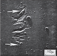
An image depicting a damaged front facet of a laser diode, fractures and droplets are clearly visible on the facet surface. The arrows show the location of the p-n junction.[1]
Most laser diodes are exceptionally sensitive to temperature effects. Diode lifetime, threshold current, lasing wavelength, lasing power, mode hoping, and linewidth among other properties are all heavily influenced by the temperature of a diode. For instance, a general rule of thumb is that for every 10 °C rise in temperature, the diode's lifetime decreases by half. Swings in the temperature of the environment will cause swings in the diode temperature as well. Even running the diode itself will cause it to heat up if not properly thermally regulated. It is recommended that proper temperature control be implemented and operating temperatures well below the max rating employed.
Power damage is often overlooked until its too late, but it is important to keep in mind the effects of power on the laser diode. Partly this suggestion relates to thermal effects, as increasing the current (to increase the power) will dump more heat into the laser chip; with inadequate thermal regulation, thermal effects and damage can take place. Perhaps slightly less obvious is the effect of back reflections into the laser diode. For systems with large reflections, running at high power risks damage to the front facet of the laser chip. It is important to know the reflections within a system and to determine if the reflected power is higher than the damage level of the diode. For systems with significant back reflections, an optical isolator can be used to reduce the feedback.
Signs of Damage
How can you tell if a laser diode is dead? A dead diode laser may still lase but will exhibit very stark performance issues from nominal. Strong reduction in output power, significant increase in threshold current, or noticeable changes in the spatial profile can be signs that your diode laser is dead. Laser focusing and collimation will also be adversely affected when the laser chip has been damaged. The beam may diverge more quickly or will not be able to be focused to as tight of a spot as previously. If the laser has been damaged to the point where it will not lase, no light other than spontaneous emission will be observed. It is not possible to fix a dead or broken laser diode; however, identifying the mechanism that terminated the diode will help avoid future destructive events.
Section 2: Laser Diode Specifications
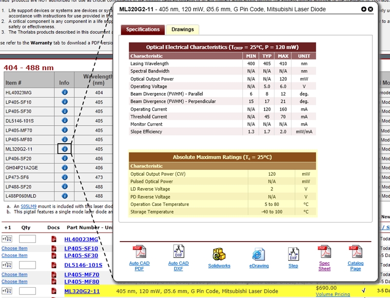
With so many parameters quantifying laser diodes, it can be easy to get lost in the garden of specifications. We will discuss here the important parameters of the specification sheet and what should be considered when setting values for your operating conditions. Each diode has a set of specifications labeled "Absolute Maximum Rating" given for a specific temperature (see image to the right). These absolute maximum ratings for CW output power, reverse voltage, and operating and storage temperature should never be exceeded. In addition to the spec sheet, you can also find these absolute maximum rating specs by clicking on the blue info icons on our web pages (see image to the lower right).
Maximum Power Output
It should be noted that the absolute rating is on output power, not on drive current. While there is a spec for operating current, which will give a good guideline for proper current range, there are always slight variations in performance from diode to diode. The maximum current specification is the maximum current that may be required to achieve the specified output power, not necessarily the maximum current that can be applied to the laser diode. It is suggested, and a good practice, to measure the power vs current curve once the user sets up a diode system (including temperature regulation).
As discussed above in the power damage mechanisms section, reflections can be a source of concern, especially if the user is operating at or near the absolute maximum output power. For systems with significant feedback into the laser, the absolute maximum output power may be lower than that listed in the spec sheet. This is due to a larger flux of photons incident upon the front facet of the diode chip, which could lead to diode damage. Care should be taken when operating near or at the absolute maximum output power in order to prevent laser diode damage.
Maximum Temperature Range
The absolute rating for temperature is another specification to be wary of. In the damage mechanisms section above, we discussed the effects of temperature on a laser diode. Running the laser diode at higher temperatures will lower its lifespan significantly. The upper limits given by the absolute rating for temperature are operable temperatures, but it is generally a good idea to avoid the upper limit. Not only will the user decrease the lifetime of the diode by running so hot, it will also leave the user susceptible to transients or other events that could cause temporary loss of thermal regulation, thereby allowing the diode temperature to spike above the maximum rating.
The specification sheets will often list a temperature for the electrical/optical characteristics, often times falling in the range of 20 – 25 °C. The listed temperature is the regulated temperature of the laser diode during the time that the specifications were measured. Temperature has a significant effect on these levels. For instance, as temperature increases so does the threshold current; running hot may shift the actual threshold current of the diode above those specified in the electrical/optical characteristics section. Standard thermal regulation typically is chosen between 20 – 25 °C for lifetime and power concerns. However, it is up to the user to determine the ideal temperature at which to regulate the laser diode.
Section 3: Diode Packages
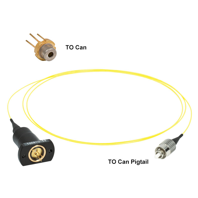
The most important factor when choosing a laser diode is most likely wavelength. Another highly important factor is diode packaging. There are several forms of diode packaging, each with their own advantages and disadvantages. Generically they can be broken down into TO cans (this would include TO can pigtail), butterfly, and submount/C-mount packaging (see image to the right). The "correct" choice of packaging is largely dependent upon intended use and lab requirements, and users should research carefully the packaging options to best match their needs to an appropriate diode.
TO Cans/TO Can Pigtails
TO cans are one of the most prevalent packaging options for laser diodes. They are simply cylindrical packages, often times hermetically sealed. Thorlabs offers five sizes for TO cans, Ø3.8 mm, Ø5.6 mm, Ø9 mm, Ø9.5 mm, and TO-46. The TO can is composed of a laser chip, a photodiode used to monitor the power at the back facet, and a heat sink. Because of the standardized sizes, TO cans are interchangeable (always be careful to note pin configuration). Additionally, they are widely available in a multitude of wavelengths and are relatively cheap. These diodes will require a bit of set up on the part of the user. For instance, building an external feedback cavity will allow the user to control the wavelength of the diode. Like all diodes, they will require thermal regulation that needs to be user supplied.
TO cans also come pigtailed with either SM, PM, or MM fiber.
Butterfly
Butterfly packages use the same chips as TO cans. Unlike TO cans, this package contains many components inside the packaging itself. This makes the butterfly packages more "plug-and-play" than the TO cans. These packages contain the laser chip and monitoring photodiode just like the TO can but additionally boast an integrated TEC and thermistor. Because these temperature elements are integrated into the packaging, it can give more accurate measurements of chip temperature and better thermal regulation when used with a proper PID temperature controller. These packages come fiber coupled with either SM or PM fiber and are available in many popular telecom wavelengths.
C-Mount/Submount
C-Mount and Submount laser diodes are specialty packages, normally used for higher power diodes or MIR sources. The submount and C-mount package provides greater thermal contact with the laser chip and the package, allowing for more efficient temperature regulation. Currently all of our MIR laser diode sources come in the two-tab C-mount package. Like the TO can, additional setup is required for these package types. There is no monitor photodiode, so the user must use caution to avoid overdriving. All temperature regulation must be provided by the user as well (no integrated TEC or thermistor). The C-mount and submount package are ideal for OEM and MIR applications.


Section 4: Selecting a Mount and Driver
Once you have chosen a laser diode, you must choose mounting and driver options. In general, the choice of mount and driver will match the laser diode and application needs. For example, if temperature regulation is necessary (for most applications this is necessary), a mount with an integrated TEC would be preferred and a driver system that matches the laser's current rating and TEC requirements would be necessary. Below are some of the basic considerations when choosing a mount and driver for your laser diode.

Click to Enlarge
LM9F with a Ø5.6 mm Adapter and Laser Diode
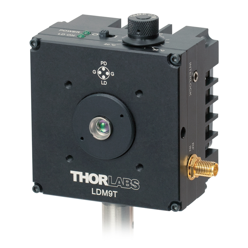
Click to Enlarge
LDM9T with S1TM09 Adapter and Mounted Aspheric Lens
Laser Diode Mounts
TO can laser diodes have a diverse variety of mounting options, including unregulated and regulated temperature mounts. For many applications temperature regulation is recommended, if not necessary. Thus, the unregulated mounts are for applications that do not need temperature regulation or systems that will incorporate user-supplied temperature regulation. If temperature regulation is unnecessary, it should still be noted that long-term operation of a thermally unregulated laser diode will considerably reduce its lifetime. Unregulated mounts include our laser diode collimation tubes, cage-compatible collimation packages, and diode mounts.
- Collimation tubes are a very common mount for TO can laser diodes; they include an aspheric lens for collimation and are typically installed into systems with external temperature regulation.
- Cage-compatible collimation kits allow the user to integrate Ø5.6 mm, Ø9 mm, and TO3 can lasers into a 30 mm cage system. This kit contains all the mounting hardware necessary for collimating the laser diode, but the user will need to select the appropriate aspheric lens for their application needs.
- Diode mounts are the simplest mounting solutions. Options are available for Ø5.6 mm and Ø9 mm TO can lasers as well as TO can pigtailed lasers.
Thorlabs also offers a variety of temperature-controlled mounting options for TO can lasers. When choosing a mount with integrated cooling, be sure the mount can handle the necessary current for the laser diode and can provide adequate heat removal.
- For high-power lasers, our High-Power TE-Cooled Laser Diode Mounts can support up to 8 W of thermal regulation and 2 A of laser diode current. Additionally, these mounts allow for current modulation of the diode. The mounts will require an external current and temperature driver, which is also available in a kit with this mount. The S1TM09 adapter allows the user to mount an aspheric lens for collimation.
- The LDM21 Laser Diode Temperature-Controlled Mount is a smaller version of our high-power mounts. This mount can support up to 2 W of thermal regulation and 500 mA of laser diode current but lacks the ability to modulate the current. Again, the S1TM09 adapter may be used to mount an aspheric lens for collimation.
- The LDM9T Laser Diode Mount with Integrated Temperature Controller is designed for lower power laser diodes. This mount can support thermal regulation up to 0.5 W and up to 1 A of laser diode current with an input for current modulation. The temperature driver is incorporated into the mount itself, requiring only an external current driver. A low-noise fan aids in the removal of heat and aids in temperature stabilization. The S1TM09 adapter allows the user to mount an aspheric lens for collimation.
- The HLD001 Laser Diode Mount with Thermoelectric Cooling is a simple temperature-controlled mount that can support up to 6.3 W of thermal regulation. It is designed specifically to be integrated into our multi-axis flexure stage.
- The LDM9LP LD/TEC Mount was designed specifically for pigtailed TO can lasers. This mount can support up to 7 W of thermal regulation at up to 1 A of laser current. Additionally, it allows the user to modulate the current. An external current and temperature driver is necessary for operating this mount.
Drivers
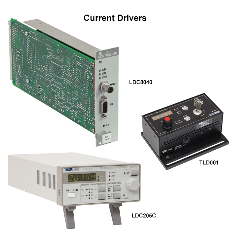
In most applications, a current source and temperature controller will be necessary. It is important to note that laser diodes are current devices, and as such, they need a current source and a voltage source. A voltage source does not carefully control its current, allowing the current to change quickly and putting the laser diode at risk. However, not all current supplies are made the same, and there are a few options you'll want to look for when choosing a driver. A shorting output (i.e., when the output leads are kept at the same potential while the laser is not in operation) is a nice feature of a laser diode current driver and helps protect against ESD damage. A slow or soft start feature allows the current to come up slowly when the output is engaged. This helps protect against transients and excessive current drive. To prevent against accidental excess drive on the part of the user, an adjustable current limit is desirable. Additionally, the current limit needs to feature a modulation clamp so that, if the user is modulating the current near the limit, the circuit is prevented from exceeding the hard limit. Be sure to set the current limit appropriately for your laser diode. Other helpful features include over voltage protection and power line transient suppression. Choose a current supply with a maximum current that is near the maximum operating current of your laser diode. Not only will this give added security against overdriving, but certain parameters (such as transient suppression) scale with maximum current rating of a current source.
- The LDC series of current controllers are a popular choice that can meet most laser diode needs and are available in both low power and high power models. These current supplies are quiet and feature shorting outputs, slow start, and an adjustable current limit with modulation clamp.
- The PRO8 rack controllers offer all the necessary protections necessary for laser diode operations of the LDC series. Geared more towards industrial applications, these controllers can safely operate multiple laser diodes. Options for Ethernet capabilities allow remote operation.
- The K-Cube™ Laser Diode Controller uses the integrated Kinesis® software to drive a mounted laser diode with any pin configuration. The unit can be operated using the top-panel controls or by PC via USB connection.
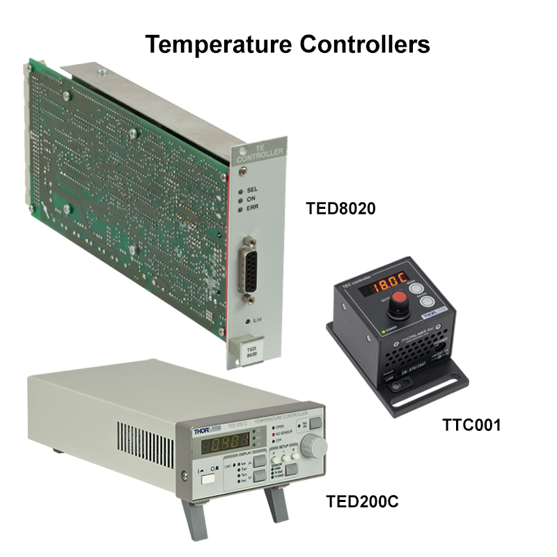
Common cooling techniques for laser diodes revolve around thermo-electric coolers (TECs). By controlling the current through the TEC, a laser's temperature can be well regulated about a predetermined set point. Since stability and lifetime are strongly tied to diode temperature, regulation is almost universally a must. A temperature controller will need to be able to source the current necessary for the cooling system and should contain a current limit. Set this below the maximum rating for the TEC to avoid damage. If creating your own cooling system, a temperature controller with an adjustable PID circuit will be required so that you may tune the circuit's performance to meet the thermal requirements of your system. In general, PID loop control is required for a proper temperature servo.
- The TED series of temperature controllers can meet the needs of most any temperature regulation series. These temperature controllers offer excellent stability, resolution, temperature range, adjustable PID parameters, and a large temperature window. The TED200C supplies up to 12 W of thermal regulation at ±2 A. For applications requiring substantial heat removal, the TED4015 provides up to 225 W of thermal regulation at ±15 A.
- The TTC001 T-Cube controller offers stable, long-term temperature stabilization, features adjustable PID settings, provides up to 4 W of thermal regulation at ±1 A, and is computer controllable through our APT software.
- The PRO8 rack temperature controllers offer excellent stability, adjustable PID parameters, and options for cooling power from 16 W to 64 W. Geared more towards industrial applications, these controllers can safely regulate multiple laser diodes. Options for Ethernet capabilities allow remote operation.
Thorlabs also offers a variety of dual current and temperature controllers for laser diodes. These dual controllers offer the reliability and protection of their independent counterparts while offering a compact and convenient single package. All the same considerations listed above apply to these controllers. Be sure to investigate the properties and capabilities of these dual controllers to evaluate whether or not they are appropriate for your system.
Helpful Tips
Proper design and control of a laser diode system can ensure over 100,000 hours of stable, reliable operation. It is worth the time and effort to ensure that the system you build will promote a safe and protected diode environment. When choosing a laser diode, be sure to carefully read the specification sheets, make note of its maximum ratings, and pair it with the appropriate drivers. Always follow proper handling techniques such as wearing gloves and antistatic wrist straps. Any equipment that comes into contact with the laser diode (such as soldering irons) and work areas should also be properly grounded. If designing your own thermal regulation system, ensure that it is appropriate not only for your laser diode but for your lab environment as well. Where does the heat go? Is your thermal mass large enough to absorb the heat from the laser diode while radiating it out to the environment (a small thermal mass can promote thermal runaway if it cannot get rid of the heat fast enough).
Despite all the precautions that can be taken in choosing a laser diode, mount, and drivers, there are always environmental concerns to consider when setting up your laser diode system. Some are easy and rather obvious; others may not be quite so intuitive. Make sure all your connections are tight and secure and that any solder joints are robust, as loose connections pose a considerable threat to the wellbeing of a laser diode. Secure cables to your optical table to prevent bumping or tugging. Long wire pairs should be avoided if possible. Long electrical leads and wires act as antennas and can pick up noise from the environment. If long cables are necessary, try to use twisted pairs to reduce low-frequency noise that can result from inductance. If high-frequency noise is a problem, shielding the cable with grounded braid can help reduce the noise. Even cables that are already shielded can sometimes pick up high-frequency noise, and an additional, external shield may be required. Be sure both ends of the shield are connected to a low-inductance earth ground.
Ground loops, electrical fast transients, and radiated transients are a large source of laser diode noise and performance issues. These can be rather difficult to track down but should be kept in mind when diagnosing performance problems. Plan for enough space between equipment to avoid pick up issues; equipment such as high current switching supplies can induce considerable voltages, which can affect the performance of a laser or even damage it. Proper grounding and lab planning can help ensure a long and healthy laser diode life. For more answers and solutions for diode selection and operation, please contact Tech Support.
[1]: D. A. Shaw, P. R. Thornton, "Catastrophic and Latent Damage in GaAs Laser Diodes," Solid State Electronics, 12, 919-24 (1970).
One of the most overlooked considerations when dealing with laser diodes is how to mount it into a system. This not only refers to the physical mechanism through which you attach a laser diode for collimation and usage but also how the diode is mounted. How long are the cables? Are they shielded? Is your mount electrically isolated from earth ground or the optical table? What equipment is nearby? How can it affect the performance? These are all questions that need to be considered.
Section 1: Diode Mounts
Selecting the appropriate mount for your diode requires consideration of diode package and application. A low-power TO can diode that will be used only for alignment, for instance, would not necessarily require thermal regulation; hence, a standard diode mount may suffice. On the other hand, a high-power butterfly package where wavelength and power stabilization are necessary would require a mount that could provide stable current and temperature control, such as the CLD1015.
In most standard laser diode applications, temperature stability is required. If you are installing your laser diode into an existing temperature servo, an unregulated mount that is easily installed into a setup, such as our collimation tubes, would be a good choice. Thorlabs offers a wide selection of diode mounts with integrated TECs (such as the LDM9T) that eliminate the need to build a temperature regulation system. If thermal regulation is necessary, make sure that the mount you choose is sufficient to handle the current and heat load for the diode.
Click to Enlarge
LM9F Post-Mountable Diode Mount with a Ø5.6 mm Adapter and Laser Diode
Thermally Unregulated Mounts
Temperature unregulated mounts are for low-power or low-duty-cycle applications or systems that will incorporate user-supplied temperature regulation. For example, an alignment laser with low power output that is not run continuously would not require temperature regulation since there is little concern over wavelength and power stability and the laser is often turned off. If temperature regulation is unnecessary, it should still be noted that long-term operation of a thermally unregulated laser diode will considerably reduce its lifetime. Since these unregulated mounts only house the diode and sometimes a collimating lens, there are no electrical connections. Thorlabs offers sockets for those interested in wiring their own diodes and electronics. Additionally we offer ESD protection and strain relief cables for TO can lasers. These cables are socketed on one end for the laser diode; the other end terminates in either bare wire or a D89 connector that is compatible with our current controllers. If choosing one of these cables, be sure that the cable purchased supports the pin style of your diode.
- Collimation tubes are very common mounts for TO can laser diodes. They include an aspheric lens for collimation and are typically installed into systems with external temperature regulation. The included lens is AR coated for 650 - 1050 nm and are offered in either 1 of 4 focal lengths or as lens pairs.
- Cage-compatible collimation kits allow the user to integrate Ø5.6 mm, Ø9 mm, and TO3 can lasers into 30 mm cage systems. These kits each contain all the mounting hardware necessary for collimating the laser diode, but the user will need to select the appropriate aspheric lens for his or her application needs.
- Diode mounts are the simplest mounting solutions, providing a housing for the laser diode but lacking any integrated mount for a collimation lens. These mounts allow any Ø5.6 mm or Ø9 mm TO can laser to be mounted on a post or installed into an SM05 or SM1 lens tube system. A mount for post mounting a TO can pigtailed laser is also available.
- Mount for One-Tab C-Mounts are a specialty mount designed specifically for our low-power, one-tab C-mount lasers. These mounts utilize heat sinks to provide up to 2 W of passive thermal regulation. There is no TEC incorporated into these mounts, so they cannot provide active thermal regulation. One-tab C-mounts are only compatible with our legacy one-tab C-mount laser diodes.
Click to Enlarge
LDM9T Regulated Diode Mount with S1TM09 Adapter and Mounted Aspheric Lens
Regulated Mounts for Free Space Diodes
Thorlabs also offers a variety of temperature-controlled mounting options for TO can lasers. These mounts support various pin configurations, but prior to purchase, ensure that the mount can support the pin style of your diode. Additionally, ensure that the laser diode is installed in the correct orientation for its pin style and that any possible modifications or settings for compatibility are made. Temperature-regulated mounts provide a direct socket for mounting diodes, so additional cables or sockets are unnecessary. When choosing a mount with integrated cooling, be sure the mount can handle the necessary current for the laser diode and can provide adequate heat removal.
- The LDM21 Laser Diode Temperature-Controlled Mount is a compact, temperature-regulated mount. It can support up to 2 W of thermal regulation and 500 mA of laser diode current but lacks the ability to modulate the current. This mount will require both an external current source and temperature controller. It supports Thorlabs' A, B, C, D, and E pin configurations. Additionally, the housing is equipped with SM1 (1.035"-40) threads, making it compatible with our 30 mm cage system. The S1TM09 adapter may be used to mount an aspheric lens for collimation.
- The LDM9T Laser Diode Mount with Integrated Temperature Controller is designed for lower power laser diodes. This mount can support thermal regulation up to 0.5 W and up to 1 A of laser diode current with an input for current modulation. The temperature driver is incorporated into the mount itself, requiring only an external current driver. A low-noise fan aids in both the removal of heat and temperature stabilization. The LDM9T supports Thorlabs' A, B, C, D, E, G, and H pin configurations. The housing is equipped with SM1 (1.035"-40) threads and 4-40 taps for lens tube and 30 mm cage system compatibility, respectively. The S1TM09 adapter allows the user to mount an aspheric lens for collimation purposes.
- The HLD001 Laser Diode Mount with Thermoelectric Cooling is a simple temperature-controlled mount that can support up to 6.3 W of thermal regulation. It is designed specifically to be integrated into our multi-axis flexure stage.
- For high-power lasers, our High-Power TE-Cooled Laser Diode Mounts can support up to 8 W of thermal regulation and 2 A of laser diode current. Additionally, these mounts allow for current modulation of the diode. The mount will require both an external current and temperature driver, which are also available in a kit with this mount. The mounts support Thorlabs' A, B, C, D, E, G, and H pin styles. The housing has SM1 (1.035"-40) threads and 4-40 taps for lens tube and 30 mm cage system compatibility, respectively. The S1TM09 adapter allows the user to mount an aspheric lens for collimation.
Click to Enlarge
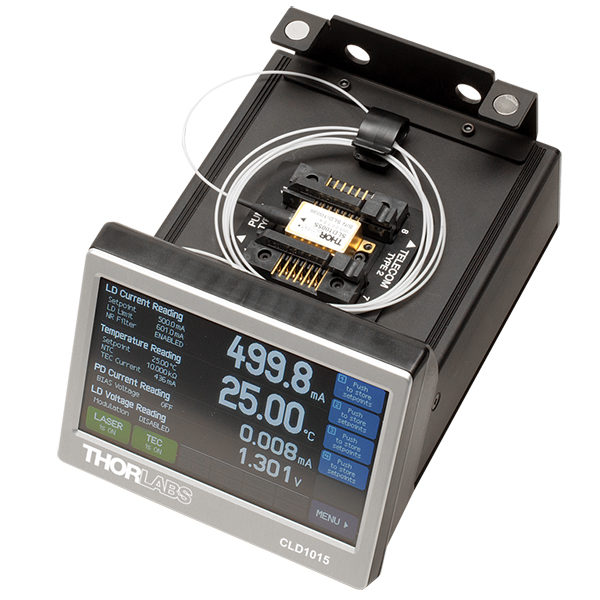
CLD1015 All-in-One Butterfly Controller with Installed Butterfly Laser
Regulated Mounts for Fiber-Coupled Diodes
Thorlabs offers a special thermally regulated mount for our TO can pigtailed laser diodes as well as a line of mounts for butterfly-packaged diodes. Since the butterfly package has an integrated TEC, all mounts for it are essentially regulated and require only the appropriate temperature controller to implement.
- The LDM9LP LD/TEC Mount was designed specifically for pigtailed TO can lasers. This mount can support up to 7 W of thermal regulation at up to 1 A of laser current. The large surface area ensures excellent thermal contact for stable temperature control. Additionally, it allows the user to modulate the current. The LDM9LP can support Thorlabs' A, B, C, D, E, G, and H pin styles. An external current and temperature driver is necessary for operating this mount.
- The LM14S2 Universal Butterfly Mount is compatible with both type 1 and type 2 14-pin butterfly laser diodes. This mount incorporates heat fins to aid in radiating the heat generated by the laser diode away from the mount and supports a maximum of 5 A for both laser diode current and TEC current. A bias-T allows the laser diode to be current modulated up to 500 MHz. The LM14S2 requires both an exeternal current source and temperature controller.
- The CLD1015 All-in-One Butterfly Laser Controller comprises a complete driver package for all of Thorlabs' 14-pin butterfly laser diodes. It contains the mount, current driver, and temperature controller all in one package. The 1.5 A internal current supply capability and compatibility with both type 1 and type 2 diodes ensure that this controller is compatible with all of Thorlabs' 14-pin butterfly laser diodes. The 3.5 A internal temperature controller can hold the diode to within 0.01 °C of setpoint. The large, front face touch screen allows complete operation of this unit with no additional equipment. Remote operation is also possible via a mini-USB connector on the back side of the unit.
Section 2: Mounting in a Lab Environment
It may not be the first thing you think about, but planning the lab environment can significantly reduce the potential for noise pick up or laser diode damage due to transients. Something as innocuous as grounding equipment can produce large headaches if not properly planned out. For instance, electrically isolating your laser diode setup from the optical table can help reduce effects caused by ground loops. While many of the regulated mounts are hardwired to earth ground so are many pieces of electrical equipment (such as oscilloscopes) commonly found in a lab. This can lead to large ground loops, and large ground loops mean large inductive noise. By placing Kapton tape under a mount, electrical contact between the mount and table will be broken, providing some protection from the effects of ground loops.
Your environment can significantly affect the sensitivity to transients. While it will be impossible to remove all transient noise and damage, with a little bit of planning, these effects can be greatly reduced. There are two sources of transient events that are of particular concern in the modern laboratory: electrical fast transients (EFTs) and electromagnetic interference (EMI). EFTs are very fast, high frequency electrical spikes. Some common sources of EFTs include equipment that draws large power line surge currents, such as motors or soldering irons, and anything with a switching power supply, such as power bricks and computers. A quick kick from an EFT may be all that’s needed to destroy a laser diode. The second common source of transients in many labs are EMIs. EMI sources have large potential to induce voltages in laser diodes sufficient to cause damage or destruction depending on proximity to the source. Common sources of EMIs include fluorescent lamps and high voltage supplies for gas or excimer lasers.
Another important factor to keep in mind is proximity to heat sources. Proper and safe operation of laser diodes typically involves temperature stabilization, which requires the radiation of heat to the environment for proper regulation (usually through a heat sink or thermal load such as a large aluminum block). If the temperature around the diode heats up, the efficiency at which heat can be moved from the diode to the environment is affected and could lead to thermal runaway. Without proper temperature regulation, a diode can succumb to thermal damage. The laser head of a 100 W CO2 laser, for example, would be a significant source of thermal pollution.
When mounting your diodes onto your laboratory table, taking stock of the equipment in the immediate vicinity can help you identify potential sources of EFT and EMI radiation as well as thermal sources. In general, you want to try to maximize the distance between these sources and your laser diode. For instance, you would not mount your laser diode directly next to the high voltage supply or head of a high-power CO2 gas laser. The cables running to your diode should be isolated from other cables, as this can help reduce pick up from other instruments.
Choosing Collimation and Ellipticity Correction Optics for Your Laser Diode
Since the output of a laser diode is highly divergent, collimating optics are often necessary. Due to their excellent ability to correct spherical aberration, aspheric lenses are the most commonly used optics when the desired collimated beam waist is between one and five millimeters. Choosing an appropriate aspheric lens for collimating a laser diode is essential, as the resulting beam size and transmission range are dependent on the lens used. To calculate the beam size of a collimated laser diode, we first need to know its divergences.
The beam divergences of an edge-emitting laser diode will be different in the parallel and perpendicular directions, leading to an elliptical beam. This can be compensated for by inserting anamorphic prism pairs or cylindrical lenses into the collimated beam. The divergences are typically specified as "Beam Divergence (FWHM) - Parallel" and "Beam Divergence (FWHM) - Perpendicular" for the two axes of the chip. There are variations from lot to lot of laser diodes, but using the typical divergence values should be adequate for most applications.
The simple example below will illustrate the key specifications to consider when choosing the correct optics for a given application.
Example: 785 nm, 25 mW Laser Diode, L785P25, Ø3 mm Desired Collimated
Step 1: Collimating Emission
The specifications for the L785P25 laser diode indicate that the typical perpendicular and parallel beam divergences are 30o and 8o, respectively. The major (perpendicular) beam divergence is shown in Figure 1. The minor (parallel) beam divergence is shown in Figure 2. Because of this asymmetry in the two axes, an elliptical beam will form as the light diverges. To collect as much light as possible during the collimation process, consider the larger of these two divergence angles in any calculations (i.e., in this case use 30o).
Note: Parallel and perpendicular notation are specified relative to the junction plane of the laser diode.
Figure 1. Perpendicular beam divergence from L785P25 style B laser diode
Figure 2. Parallel beam divergence from L785P25 style B laser diode
In the above schematics, LD denotes the laser diode,  and
and  are the beam diameters in the parallel and perpendicular orientations, respectively, and
  and
and  are the divergence angles in the parallel and perpendicular orientations, respectively. Please note that the notch in Figures 1 and 2 can be used to determine the orientation of the laser diode within the package. Laser diodes are typically oriented parallel to the notch; however there are many exceptions, especially for different laser diode packages. Care should be taken to note the orientation of the laser diode emission.
To calculate the focal length needed to achieve a Ø3 mm collimated beam diameter, we can use:
where  is the focal length that produces the desired perpendicular beam diameter, . The focal length of the lens needed to collimate a 30o diverging beam into a Ø3 mm collimated beam is = 5.6 mm.
This equation yields the focal length to achieve our desired major (perpendicular) axis diameter. Use this to then select an aspheric lens with a focal length that most closely matches the focal length given by the equation. Please note that the diameter of the lens must be larger than your desired major axis beam diameter.
Thorlabs offers a large selection of aspheric lenses. For this application, the ideal lens is an -B AR-coated molded glass aspheric lens with focal length near 5.6 mm. The C171TMD-B (mounted) or 354171-B (unmounted) aspheric lenses have a focal length of 6.20 mm. Next, check to see if the numerical aperture (NA) of the diode is smaller than the NA of the lenses so that the light emitted from the laser diode is not clipped by the lens:
0.30 = NALens > NADiode ~ sin(15) = 0.26
Figure 3. Anamorphic Prism Pair and optic trace for an ellipse to round beam.
Solving the first equation again with your actual focal length and major axis divergence angle yields the actual major axis beam diameter, = 3.3 mm.
Step 2: Correcting Ellipticity
Emission from an edge emitting laser diode is elliptical (asymmetric with respect to two different axes), as shown in Figures 1 and 2. To correct for this and produce a circular beam, the minor axis diameter, , can be magnified using anamorphic prism pairs or cylindrical lenses after collimation. Note: only cylindrical lens pairs can correct for any astigmatism present in the diode output. Figure 3 shows an anamorphic prism pair magnifying an elliptical beam minor axis to produce the desired symmetric beam.
To determine what magnification of the minor axis is needed to produce a round beam, solve Eq. 1 using the focal length from the aspheric lens,![]() = 6.20 mm, = 8o, instead of the major axis divergence. This results in a minor axis diameter, = 0.9 mm. Comparing and , we see that a 3.5X magnification is necessary in the minor beam axis. This 3.5X magnification can be achieived using the PS881-B Mounted Anamorphic Prism Pair.
= 6.20 mm, = 8o, instead of the major axis divergence. This results in a minor axis diameter, = 0.9 mm. Comparing and , we see that a 3.5X magnification is necessary in the minor beam axis. This 3.5X magnification can be achieived using the PS881-B Mounted Anamorphic Prism Pair.
Lens Tube Mounting
For mounted aspheric lenses, our SM05Txx or S1TMxx adapters can be used. Take care to ensure that the lens does not contact the laser diode. The SM05Txx adapters will require the use of an SM1A6T SM1-to-SM05 adapter.
Unmounted aspheres can be epoxied to an LMRAxx adapter, which can then be mounted in an SM1A6T SM1-to-SM05 adapter. The SM1 threading of the adapter can then be used to attach the lens/mount/adapter to the laser diode mount's front plate. The SM1A6T adapter has a mounting range of 10 mm, covering almost the entire focal length range of our aspheric lenses.
In the above example, the C171TMD-B mounted lens features M8 x 0.5 threading, thus requiring the S05TM08-threaded adapter. The S05TM08 M8-to-SM05 adapter can be mounted in the laser diode mount using the SM1A6T SM- to-SM05 adapter. The correct distance between the laser diode and lens can be achieved by adjusting both the S05TM08 and the SM1A6T adapters.
If the 354171-B, unmounted ashperic lens is used, it must first be epoxied to the LMRA5 adapter. It can then be mounted in the SM1A6T SM1-to-SM05 adapter. Again, adjustment of the aspheric lens can be made at the LMRA5 and SM1A6T adapters.
Cage Assembly Mounting
Mounted and unmounted aspheric lenses with focal lengths greater than 8 mm can be cage mounted using our 30 mm cage system. Cage rods can be attached directly to the front plate of the laser diode mount. The CP33(/M) cage plate may be used to hold the S1TMxx adapter with mounted aspheric lens or the SM1A6T adapter with unmounted aspheric lens epoxied to an LMRAxx adapter.
For larger translational adjustments, the CT1A(/M) 1/2" Travel Translator can be used. The CT1A(/M) translator has a graduated micrometer which provides 1/2" (13 mm) of linear translation and has 0.001" (10 µm) graduations. The smallest incremental movement of the carriage is approximately 1 µm.
Anamorphic Prism Pair Mounting
The asymmetric output of the laser diode can be corrected using either anamorphic prisms or cylindrical lenses. As determined in the example above, a 3.5X mounted anamorphic prism pair (i.e., PS881-B) was needed to produce a round beam profile. Unmounted prisms may be used as well.
The PS881-B Mounted Anamorphic Prism Pair features SM05 threading on the output end or may be mounted inside an SM1 Lens tube. Since the input and output beams from the Anamorphic Prism Pair are offset from each other, prisms should be mounted on another cage or lens tube axis.
Choosing the correct laser diode controller is essential for proper diode performance and longevity. In this section, we will look at some of the necessary considerations when picking the right controller for your laser diode. Most laser diode drivers also allow for direct analog modulation, a feature that is useful for tasks such as linewidth broadening and wavelength stabilization as well modulating a laser's emission on/off. We will look at the fundamentals of driver modulation and examine some of the pitfalls and limitations commonly experienced with modulation.
Section 1: Laser Diode Driver Basics
The ideal laser diode controller would be a linear, noiseless, and accurate constant current source. Laser diodes are intrinsically current devices, and hence, direct and accurate current control is necessary for precise diode operation. It is important to note that voltage controllers cannot accomplish this task. While they do carefully ramp voltage when turned on, they do not regulate the current, which could allow significant - and possibly disastrous - current oscillations to transmit to the diode. Do not use a constant voltage source to drive a laser diode.
Current controllers are designed to offer direct and linear current control and can drive diodes over a broad range of impedances. Additionally, they are low noise sources. Current noise is turned into frequency noise by the laser diode. For certain broadband lasers, this may not be particularly noticeable. However, the effects of noise are exacerbated in stabilized wavelength or narrow linewidth lasers, such as single frequency lasers, where precise operation is necessary.
In addition, current sources are designed so that they will not increase the current if it reaches the compliance voltage; this is something a constant voltage source cannot do (and yet another warning against using a voltage source to drive a laser diode). The compliance voltage is typically an innate property of the current driver, though some models have an adjustable voltage limit, be sure that the compliance voltage of the current driver is appropriate for your laser diode. It should be noted that when the current is controlled directly through a feedback loop, the loop response needs to be controlled. This is to prevent overdriving the laser diode. Full control of the feedback loop is required.
With the generalities out of the way, there are some key characteristics of current supplies that should be considered before making a purchasing decision. The current supply needs to be tailored to the laser diode; there is no one-size-fits-all current source. For instance, if you have a laser diode with a maximum current rating of 180 mA, choose a current supply with a maximum output as close to that as possible (such as 200 mA in this case).
Current noise from a source scales with maximum output current. If you use a 1 A source for a 180 mA laser, you are needlessly introducing noise into the system. Additionally, it is easy to apply too much current if one is not careful, needlessly risking the lifetime of the laser diode. It is best to match the driver to the diode. Additionally, all laser diode current controllers will feature a shorted output, slow-start, over-voltage protection, power line transient suppression, and a current limit. Many also offer a constant power feature in addition to its nominal constant current operational mode.
Shorted Output
The shorted output feature helps provides protection against electrostatic discharge (ESD) damage when the diode is connected to the supply. A shorted output keeps the potential of the output leads the same when the current supply's output is off. Typically a shorted output can be implemented through a relay or a field-effect transistor (FET). The difference of note is that a relay will maintain shorting protection even when the current source itself is off, whereas an FET can only maintain its protection when the supply is powered on.
Slow-Start
The slow-start feature helps to provide protection against transients when the current source output is enabled. During slow-start, the current output to the laser diode is over-damped, which ensures a gradual increase in output current. Once the transients are suppressed, the current source will output its full current. A slow-start time of roughly 100 ms is enough to ensure that transients from enabling the output are suppressed.
Over-Voltage Protection
Over-voltage protection helps to provide protection against fluctuations in current produced by changing impedance of a circuit. High impedance loads can cause the current control circuit to saturate, preventing it from reaching the set current. Conversely, if the impedance is reduced quickly, the current control would be forced to its short-circuit limit. In either case, the laser can become overdriven, which could lead to damage. Over-voltage protection will cut the current output of the controller should the control loop saturate.
Power Line Transient Suppression
This feature helps to provide protection against AC line transients, high-voltage surges, and electronic fast transients (EFTs). Capacitive filters and properly shielded transformers help eliminate transients that make it to the current controller's power input from reaching the laser diode itself. This type of transient suppression can shield the laser diodes only from transients on the controller's power line. It should be noted that power line transient suppression cannot protect against transients that are radiated directly into the laser or drive cables (such as EFT contamination).

Click to Enlarge
Figure 1: Two examples of a current-limited supply. The red curve is the input modulation, and the blue curve is the output current. Graph A shows a supply with an ineffective current limit. Graph B shows a supply with an effective current limit, which is produced by use of a current clamp (such as those used in Thorlabs' current controllers).
Click to Enlarge
Figure 2: When a current supply is properly modulated, the output (blue curve) will follow the input modulation signal (red curve) without distortion.
Current Limit
A current limit protects against excessive drive current either through accidental adjustment, analog modulation, or constant-power operation. The current limit sets a hard limit to the current output of the controller's circuit. Not only does this feature prevent accidentally setting the current too high for a laser diode but also clamps current output in instances when modulation would produce an overcurrent (see Fig. 1). Most modern laser diode current controllers have a current limit; however, the performance may be different under analog modulation. The best current controllers can clamp the current precisely at the current limit, preventing the drive current from exceeding the current limit in all cases.
Constant Power Mode
Some models of diode drivers will feature a constant power operation mode. To utilize this feature, a laser diode needs to have an integrated photodiode. Be sure to note whether the photodiode is anode grounded or cathode grounded and ensure the proper mode is selected on the driver. It is good practice to set the power limit to a value that is below the absolute maximum power rating for the diode, as constant power operation is not as accurate as constant current operation since this mode relies on the photodiode coupling efficiency and linearity of its response.
Section 2: Laser Diode Driver Modulation
Depending on application, it may be advantageous to modulate the laser diode’s current. This can take the form of small signal or large signal modulation. For this, current controllers typically feature external analog modulation and transistor-transistor logic (TTL) inputs. Small signal modulation is a modulation that is typically a small percentage of the overall output current. It can be used for either linewidth broadening or precise control over the wavelength (such as locking the wavelength to an external signal such as a saturation absorption or dichroic atomic vapor laser lock signal).
Large signal modulation, on the other hand, can drive the output from 0% to 100% of the current setpoint. This can be done either through the analog modulation input or the digital TTL input. An analog modulation will allow the continuous modulation of current to the laser diode and, if driven by a sine wave, can realize the full modulation bandwidth. To prevent distortions in the output power of the laser diode, the lower level of the modulating signal should correspond to a current value that is just above the threshold current for the laser diode. The digital TTL modulation will modulate on/off with a square wave. It should be noted, however, that using a square wave will reduce the functional modulation bandwidth. This is because square waves contain a large number of higher frequency components.
In general, there are three parameters that must be adhered to when modulating a laser diode: modulation coefficient, input impedance, and modulation bandwidth, all of which are discussed below. These values are dependent upon the current controller and will be listed in the controller's specifications. Additionally, some drivers will feature low bandwidth (CW) and high bandwidth output modes. For such drivers, the low bandwidth setting is designed for CW output and may be unsuitable for modulation beyond low frequency, small signal modulation. The high bandwidth output mode is meant for modulation purposes and has a higher modulation bandwidth.
Modulation Coefficient
The modulation coefficient, sometimes referred to as the transfer function, is simply the conversion from modulation voltage to current output (typically given in mA/V). For example, the LDC202C has a modulation coefficient (in constant current mode) of 20 mA/V. A +1 VDC modulation signal will raise the output current by 20 mA over the setpoint (so if the controller is set to 100 mA, adding in this DC modulation signal will increase the output to 120 mA). Conversely a -1 VDC signal will lower the output by 20 mA.
Modulation can also be achieved using waveforms; if we use a 200 kHz sine wave with a peak-to-peak voltage of 2 V centered on 0 V, then the current output will be driven between 80 and 120 mA at 200 kHz (setpoint at 100 mA). Most current supplies will allow arbitrary waveforms to be used for modulation, but it should be noted that when using a waveform other than a sine wave, the modulation bandwidth will be reduced.
Input Impedance
The input impedance is the impedance of the modulation circuit integrated into the current controller. These have a nominal range of 50 Ω to 10 kΩ (the LDC202C, for instance, has an input impedance of 10 kΩ). Function generators tend to have an output impedance of about 50 Ω. This means that if the input impedance of the current controller is low, the function generator will be loaded down quite significantly, causing distortions in the output wavefunction. If this is the case, a simple trick is to set the modulation with the function generation connected to the current source but with the current output disabled. Doing so will allow you to view the modulation signal without risking the laser diode itself. Once the modulation levels and frequency are set to the desired output, the current output can be enabled.
Modulation Bandwidth
The modulation bandwidth, which is often set by the 3 dB point, is the range of modulation frequencies that can be used without significant distortion in the output current signal. The LDC202C has a small signal bandwidth of DC to 250 kHz, meaning that the current can be small signal modulated with a sine wave up to 250 kHz without significant distortion in the output current. This, again, means that using a waveform other than a sine wave will reduce the functional modulation bandwidth. A square wave, for instance, would reduce the bandwidth by about a factor of 10.
Overdriving the modulation will result in distortion and clipping in the laser diode output (see Fig. 3). Additionally, modulating at higher frequencies will induce an approximate π-phase shift between the modulation waveform and the laser diode's output intensity (though if within the bandwidth of the current source, the output will not be significantly distorted, see Fig. 4). When modulating at high frequencies with a square wave, it should be noted that there will be ringing in the output (due to the multiple higher frequencies), as shown in Fig. 5. This ringing can briefly exceed the current limit even in controllers with high-precision current clamps.
Click to Enlarge
Figure 3: When a current supply is severly overdriven with a square wave (red curve), the output (blue curve) becomes significantly distorted and cannot reach the set current limit.

Click to Enlarge
Figure 4: When a current supply is modulated at high frequencies (but still within the proper bandwidth of the controller), there is an approximate π-phase shift between input modulation (red curve) and output current (blue curve).
Click to Enlarge
Figure 5: Modulating at high frequencies with a square wave can produce ringing that exceeds the current limit setpoint.
Section 3: Thorlabs' Laser Diode Controllers
When it comes to choosing a laser diode controller, there is quite a bit to consider. However, by taking the time, evaluating the needs of the system, and matching the controller to the laser diode, the correct driver can be found, ensuring precise and long-lived operation. Thorlabs offers a diverse line of laser diode drivers.
- The LDC series of current controllers are a popular choice that can meet most laser diode needs and are available in both low power and high power models. These current supplies are quiet, providing shorting outputs, slow start, and an adjustable current limit with modulation clamp.
- The PRO8 Rack Controllers incorporate all the necessary protections necessary for laser diode operation of the LDC series. Geared more towards industrial applications, these controllers can safely operate multiple laser diodes. Options for Ethernet capabilities allow remote operation.
- The K-Cube™ Laser Diode Controller uses the integrated Kinesis® software to drive a mounted laser diode with any pin configuration. The unit can be operated using the top-panel controls or by PC via USB connection.
Thorlabs also manufactures a variety of dual current and temperature controllers for laser diodes. These dual controllers offer the reliability and protection of their independent counterparts while offering a compact and convenient single package. All the same considerations listed above apply to these controllers. Be sure to investigate the properties and capabilities of these dual controllers to evaluate whether or not they are appropriate for your system.
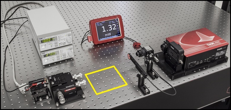
Click to Enlarge
Figure 1: The beam circularization systems were placed in the area of the experimental setup highlighted by the yellow rectangle.


Click to Enlarge
Figure 4: Spatial Filter System
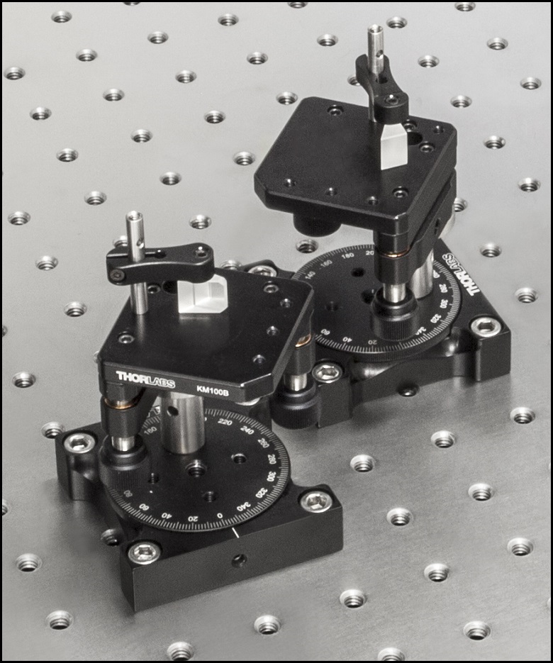
Click to Enlarge
Figure 3: Anamorphic Prism Pair System

Click to Enlarge
Figure 2: Cylindrical Lens Pair System
Comparison of Circularization Techniques for Elliptical Beams
Edge-emitting laser diodes emit elliptical beams as a consequence of the rectangular cross sections of their emission apertures. The component of the beam corresponding to the narrower dimension of the aperture has a greater divergence angle than the orthogonal beam component. As one component diverges more rapidly than the other, the beam shape is elliptical rather than circular.
Elliptical beam shapes can be undesirable, as the spot size of the focused beam is larger than if the beam were circular, and as larger spot sizes have lower irradiances (power per area). Techniques for circularizing an elliptical beam include those based on a pair of cylindrical lenses, an anamorphic prism pair, or a spatial filter. This work investigated all three approaches. The characteristics of the circularized beams were evaluated by performing M2 measurements, wavefront measurements, and measuring the transmitted power.
While it was demonstrated that each circularization technique improves the circularity of the elliptical input beam, each technique was shown to provide a different balance of circularization, beam quality, and transmitted power. The results of this work, which are documented in this Lab Fact, indicate that an application's specific requirements will determine which is the best circularization technique to choose.
Experimental Design and Setup
The experimental setup is shown in Figure 1. The elliptically-shaped, collimated beam of a temperature-stabilized 670 nm laser diode was input to each of our circularization systems shown in Figures 2 through 4. Collimation results in a low-divergence beam, but it does not affect the beam shape. Each system was based on one of the following:
- LJ1874L2-A and LJ1638L1-A Plano-Convex Convex Cylindrical Lenses (Figure 2)
- PS873-A Unmounted Anamorphic Prism Pair (Figure 3)
- Previous Generation KT310 Spatial Filter System with P5S Ø5 µm Pinhole (Figure 4)
The beam circularization systems, shown to the right, were placed, one at a time, in the vacant spot in the setup highlighted by the yellow rectangle. With this arrangement, it was possible to use the same experimental conditions when evaluating each circularization technique, which allowed the performance of each to be directly compared with the others. This experimental constraint required the use of fixturing that was not optimally compact, as well as the use of an unmounted anamorphic prism pair, instead of a more convenient mounted and pre-aligned anamorphic prism pair.
The characteristics of the beams output by the different circularization systems were evaluated by making measurements using a power meter, a wavefront sensor, and an M2 system. In the image of the experimental setup, all of these systems are shown on the right side of the table for illustrative purposes; they were used one at a time. The power meter was used to determine how much the beam circularization system attenuated the intensity of the input laser beam. The wavefront sensor provided a way to measure the aberrations of the output beam. The M2 system measurement describes the resemblance of the output beam to a Gaussian beam. Ideally, the circularization systems would not attenuate or aberrate the laser beam, and they would output a perfectly Gaussian beam.
Edge-emitting laser diodes also emit astigmatic beams, and it can be desirable to force the displaced focal points of the orthogonal beam components to overlap. Of the three circularization techniques investigated in this work, only the cylindrical lens pair can also compensate for astigmatism. The displacement between the focal spots of the orthogonal beam components were measured for each circularization technique. In the case of the cylindrical lens pair, their configuration was tuned to minimize the astigmatism in the laser beam. The astigmatism was reported as a normalized quantity.
Experimental Results
The experimental results are summarized in the following table, in which the green cells identify the best result in each category. Each circularization approach has its benefits. The best circularization technique for an application is determined by the system’s requirements for beam quality, transmitted optical power, and setup constraints.
Spatial filtering significantly improved the circularity and quality of the beam, but the beam had low transmitted power. The cylindrical lens pair provided a well-circularized beam and balanced circularization and beam quality with transmitted power. In addition, the cylindrical lens pair compensated for much of the beam's astigmatism. The circularity of the beam provided by the anamorphic prism pair compared well to that of the cylindrical lens pair. The beam output from the prisms had better M2 values and less wavefront error than the cylindrical lenses, but the transmitted power was lower.
| Method | Beam Intensity Profile | Circularitya | M2 Values | RMS Wavefront | Transmitted Power | Normalized Astigmatismb |
|---|---|---|---|---|---|---|
| Collimated Source Output (No Circularization Technique) |
 Click to Enlarge Scale in Microns |
0.36 | Y Axis: 1.63 |
0.17 | Not Applicable | 0.67 |
| Cylindrical Lens Pair |  Click to Enlarge Scale in Microns |
0.84 | X Axis: 1.90 Y Axis: 1.93 |
0.30 | 91% | 0.06 |
| Anamorphic Prism Pair |
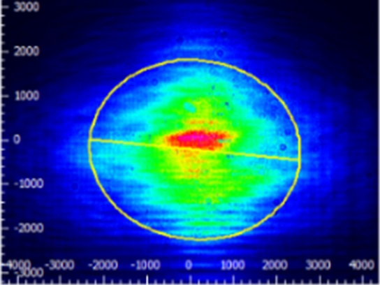 Click to Enlarge Scale in Microns |
0.82 | X Axis: 1.60 Y Axis: 1.46 |
0.16 | 80% | 1.25 |
| Spatial Filter | 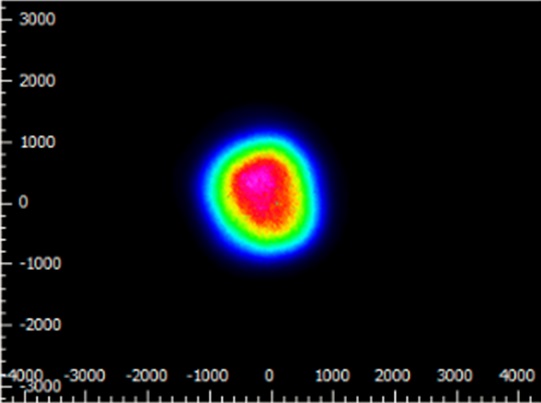 Click to Enlarge Scale in Microns |
0.93 | X Axis: 1.05 Y Axis: 1.10 |
0.10 | 34% | 0.36 |
Components used in each circularization system were chosen to allow the same experimental setup be used for all experiments. This had the desired effect of allowing the results of all circularization techniques to be directly compared; however, optimizing the setup for a circularization technique could have improved its performance. The mounts used for the collimating lens and the anamorphic prism pair enabled easy manipulation and integration into this experimental system. It is possible that using smaller mounts would improve results by allowing the members of each pair to be more precisely positioned with respect to one another. In addition, using made-to-order cylindrical lenses with customized focal lengths may have improved the results of the cylindrical lens pair circularization system. All results may have been affected by the use of the beam profiler software algorithm to determine the beam radii used in the circularity calculation.
Additional Information
Some information describing selection and configuration procedures for several components used in this experimental work can be accessed by clicking the following hyperlinks:
| Posted Comments: | |
Kurt Christenson
(posted 2019-06-15 17:52:59.143) Really appreciate the tutorials. But as an old guy, it would be nice to have a bigger font. I can enlarge the page, but then the text goes off the edges. Could you set it up so the wrap happens at the edge of the screen regardless of the zoom? lmorgus
(posted 2019-06-17 07:56:14.0) A response from Laurie at Thorlabs to Kurt: Thanks, Kurt, for taking the time to let us know you found this tutorial content helpful! Concerning the font size, we are taking a look at increasing it later this year. dave_petch
(posted 2016-08-02 08:51:53.287) Is there any way to estimate the shelf life of a laser diode? I have an application where we want to store an optical disk drive archive system for many years and play back M-disks (BDMV Format) in the future. How long could I store a Blu-ray player in an controlled environment and still have it work? sales
(posted 2015-10-02 12:50:34.567) I did enjoy :-) besembeson
(posted 2015-10-08 04:01:33.0) Response from Bweh at Thorlabs USA: Thanks for the feedback. We are glad we enhanced your understanding of laser diodes through our tutorials. tayade
(posted 2015-04-11 00:22:37.943) useful info, send me details of ur products nigel
(posted 2014-11-25 13:19:35.073) These lasers can have emission ranges from the blue (~400 nm) to the IR by combining elements from Groups II and VI or Groups IV andVI, respectively. [From your laser diode types tab]
Oh no they don't! Back to school chemistry for someone. GaN [the basis for the most used LD is a III-V semiconductor [from Groups III and V].
Group IV-VI diode would presumably be CSe? SiTe?!I also doubt if anyone is till using II-VI [ZnSe/PbS]diodes as these have been superseded by III-Vs in most case I can think of...
A glance at your Periodic Table will clarify. myanakas
(posted 2015-07-24 11:38:50.0) Response from Mike at Thorlabs: Thank you for your feedback. Your are correct, there was an error in our presentation on the "Laser Diode Types" tab. This has been corrected. Semiconductor lasers can have emission ranges from the blue (~400 nm) to the IR by combining elements from groups III and V or groups IV and VI. We apologize for any inconvenience this may have caused. |