 Products Home
Voice Coil Flexure Scanner
- ±1.75 mm Recommended Travel Range
- Full Range of Motion at Frequencies up to 30 Hz
- Very Smooth Movement
- Accepts Ø1/2" (Ø12.7 mm) Optics
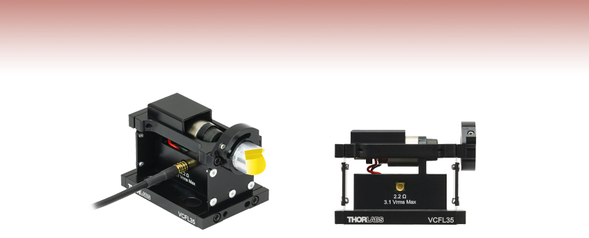
VCFL35
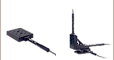
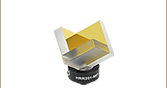
Voice Coil Flexure Scanner Shown with Retroreflector and Cable (Retroreflector Not Included)
Side View
US Patent 10,101,559


Please Wait
Features
- Recommended Travel Range of 3.5 mm (±1.75 mm from Neutral)
- Full Range of Movement up to 30 Hz with a 3.5 g Load
- Accepts Ø1/2" (Ø12.7 mm) Optics
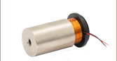
- Driven by a VC063/M Voice Coil Actuator
- Patented Optic Bore Design with Monolithic Flexure Arm (US Patent 10,101,559)
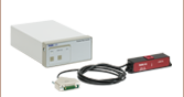
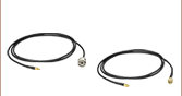
- Comes with a CA3339 MMCX Male to BNC Male Cable
The VCFL35(/M) Voice Coil Flexure Scanner provides fast, smooth motion of a Ø1/2" (Ø12.7 mm) optical element over the recommended range of 3.5 mm (±1.75 mm from flexure neutral) at frequencies up to 30 Hz with a 3.5 g mounted optic. Rapid acceleration in the range of 40 m/s2 is achievable, allowing for shorter travel ranges at higher frequencies. Rubber stops limit the full range of travel to ±2.3 mm.
The scanner consists of a stage that supports a VC063/M voice coil actuator between two flexures. Flexure bending is nearly frictionless, so that the resulting motion is smoother than many other types of bearings. Optics may be mounted on the front of the stage via a side optic retention mount using a 0.05" (1.3 mm) hex key. This mirror mount features a patented optic bore design with a monolithic flexure arm to hold the optic. Applying a voltage (up to 3.1 VRMS) to the female MMCX input connector results in a current through the voice coil, which drives the motion of the stage. Please see the Specs tab for full scanner specifications and the Operation Features tab for drawings describing mounting and electrical connections.
The smooth, fast, predictable motion of the VCFL35(/M) scanner is ideal for low- to mid-resolution interferometry, laser delay lines, and beam displacement applications. The path is approximately rectilinear, with a vertical runout that reaches about 90 µm at either extreme of travel. The vertical runout is nearly parabolic with respect to displacement in the scan axis. While the tilt of the optic is small, it is not zero and varies from unit to unit. The scanner is therefore best suited to interferometer designs that are tilt- and shear-compensated with the use of retroreflectors.
The VCFL35(/M) scanner may be operated open loop using a standard waveform generator with a variety of waveforms. Detailed information about open-loop performance for a Michelson interferometer example with various driving waveforms is given in the Application tab, including links to the driving waveform used for the application presented. Integrating the flexure scanner with user-designed systems to enable closed-loop control is also possible; see the Applications tab and the manual for more information. The Graphs tab provides additional performance information.
The VCFL35(/M) scanner comes with one CA3339 MMCX Male to BNC Male, 1 m (39") cable. The scanner can be mounted to a standard breadboard using 1/4"-20 (M6) screws at least 1/2" (12.7 mm) long or via three 1/4"-20 (M6) threaded holes on the underside, compatible with Thorlabs' height spacers, the BA2(/M) base, and other Thorlabs' bases with the same pattern of counterbores.
| Resonance Specificationsa | |||
|---|---|---|---|
| Resonance | No Load | 2 g Optic Mounted | 3.5 g Optic Mounted |
| First Resonance | 14.9 Hz | 14.1 Hz | 13.2 Hz |
| Max Scan Frequencyb | 33 Hz | 32 Hz | 30 Hz |
| First Parasitic Resonancec | > 1.5 kHz | ||
| VCFL35(/M) Specifications | |
|---|---|
| Recommended Travel Rangea | 1.75 mm |
| Maximum Travel Rangea | 2.30 mm ± 0.50 mm |
| Maximum Input Voltage | 3.1 VRMS |
| Scanner Resistance | 2.2 Ω at 23 °C |
| Maximum Continuous Currentb | 1.4 A at 23 °C |
| Voice Coil Inductance | 167 µH |
| Force Constantc | 0.71 N/A |
| Static Travel Constanta | 0.27 A/mm |
| Flexure Spring Constantd | 193 N/m ± 20% |
| Maximum Recommended Loade | 3.5 g |
| Absolute Maximum Load | 12.5 g |
| Recommended Optic Mounting Torquef | 8 oz-in |
| Minimum Optic Thickness | 3.2 mm |
| Vertical Runoutg | 90 μm |
| Dimensionsh | 57.3 mm x 38.1 mm x 42.4 mm |
| Weight | 68 g |
| Weight (Moving Stage Only) | 20 g |
| Structural Material | Aluminum, Steel |
| Input Connector | Female MMCX |
| Input Connector Mating Cycles | 500 |
| Included Cable | 1 m MMCX Male to BNC Male |
For complete mechanical drawings, click on the red Docs icon ( ) next to the part numbers below.
Click to Enlarge
To mount the optic in the front of the scanner, hold the moving platform in place and tighten the locking set screw using a 0.050" (1.3 mm) balldriver or hex key. The recommended optic mounting torque is 8 oz-in for Ø12.7 mm (+0/-0.1 mm) optics.

Click to Enlarge
Connect the VCFL35(/M) scanner to any suitable waveform generator or controller. Please see the Application tab for examples of performance for various driving conditions. The input connector to the scanner is electrically insulated from aluminum housing.
 These graphs show the Bode plot of the displacement transfer function. Bode plots provide a convenient and intuitive representation of frequency response for linear systems. The top graph above shows the magnitude of the frequency response in displacement while the bottom graph shows the phase shift. The frequency response is quite flat below the first resonance, because the system response is simply the deflection of the springs produced by the force of the voice coil.
 These graphs show the Bode plot of the velocity transfer function. The top graph in the Bode plot describes the amplitude of the response while the bottom graph describes the phase. The velocity increases with frequency, up to the first resonance. The efficient recycling of energy at the resonance causes a significant increase in velocity at, and near, the resonance. After the first resonance there is a roll off in magnitude with respect to increasing frequency.
Click to Enlarge
Click Here for Data
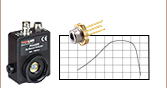
Because the magnetic field intensity is not perfectly uniform, and the overlap of the coil to the field also varies with position, the voice coil actuator within the VCFL35(/M) scanner will produce a slightly different force as a function of current depending on its position in the magnetic field. At either scan extreme (the recommended ±1.75 mm from the neutral position), the force constant will decrease by about 10%.

Click to Enlarge
Click Here for Data
The maximum scan displacement from flexure neutral when driving the VCFL35(/M) scanner directly with a waveform generator is plotted above. This graph shows the first resonance of the device around 14 Hz. Note, the displacement of the scanner is limited by rubber soft stops to prevent movement greater than ±2.3 mm.
Click for Details
The Michelson interferometer arrangement described in this tab is shown above. Click for Details for a full labeled diagram.
Michelson Interferometer Application: Open- and Closed-Loop Operation
We present here an example of the VCFL35(/M) Voice Coil Flexure Scanner in a standard Michelson interferometer configuration to demonstrate the operation of the scanner for various driving conditions.
Michelson Interferometer System
The VCFL35(/M) scanner may be configured to scan the moving arm of a standard Michelson interferometer. A diagram of a suitable optical setup, which was constructed on a vibration-isolated optical table, is shown in the figure at the right. While not used for the results presented in this example, Thorlabs' optical enclosures should be placed over interferometers when stringent isolation from environmental disturbances is required, particularly for position control. In addition, either a signal generator or PID controller is required to drive the VCFL35(/M) scanner, in open-loop or closed-loop operation, respectively.
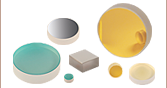
The light source for the Michelson interferometer shown in the figure at right is an FPV785P 785 nm VHG Wavelength-Stabilized Single Frequency Laser Diode collimated using an F220APC-780 Fiber Collimation Package. A CCM1-BS014 Cage Cube-Mounted Non-Polarizing Beamsplitter is used to divide the laser beam into two perpendicular beams, each containing nominally 50% of the original intensity. One beam reflects from a fixed flat mirror (Item# PF10-03-P01) and the other reflects from a PF05-03-P01 flat mirror mounted to the moving stage of the VCFL35(/M) scanner. The beams are reflected back to the beamsplitter, where they both are split again.
One of the resulting recombined beams passes to the PDA100A2 detector, which measures the intensity. The other recombined beam returns in the direction of the laser source and is lost. The PDA100A2 detector measures the intensity of the recombined beam, which changes with the optical path difference of each arm. The detector output data is sent through an ADC (analog-to-digital converter) and split into small time increments. The number of fringes per time increment is used to calculate the velocity of the scanner.
Open-Loop Operation
For open-loop operation, the VCFL35(/M) scanner may be driven with any waveform within the operating power limits. Depending on the application, the input signals most likely to be useful will be tailored to optimize the motion along a repeating trajectory. For sinusoidal waveforms, the amplitude need only be scaled correctly for the response of the scanner at the desired frequency. In some cases, such as FT-IR spectrometers, a more desirable motion profile will closely resemble a triangular waveform that exhibits constant velocity in both directions with quick turnarounds.
A detailed discussion of the resonance behavior of the flexure scanner is described in the manual. The Specs tab contains resonance information for different loads, and the Graphs tab shows performance at the resonance frequency. There is a large increase in amplitude response at the fundamental resonance, and so it is important to tailor the waveforms to not excite the resonance mode. Purely triangular waveforms are comprised of a series of harmonics that can include the fundamental resonance of the VCFL35(/M) scanner. This will result in poor velocity stability and unintentional turnarounds.
Click to Enlarge
The graphs above show a triangle waveform (left) and the velocity as a function of time for the VCFL35(/M) scanner when driven by this triangle waveform (right). The blue shaded region of the triangle waveform is the section of the waveform for which the velocity of the scanner is shown. An unwanted turnaround (circled in red) occurred before the end of the scan.

Click to Enlarge
The graphs above show a triangle waveform with the higher frequency harmonics filtered out (left) and the velocity as a function of time for the VCFL35(/M) scanner when driven by this filtered triangle waveform (right). The blue shaded region of the filtered triangle waveform is the portion of the waveform for which the velocity is shown.
The figure at the right shows a purely triangular waveform used to drive the VCFL35(/M) scanner in the Michelson interferometer system described above, along with the resulting velocity characteristics of a single scan, from one extreme to the other (3.5 mm travel). The shaded region of the triangle waveform is the section of the waveform for which the velocity of the scanner is shown.
For the example shown, the velocity stability for the center 65% of the scan is 18.6%, and this was repeatable for multiple units tested. The velocity stability is defined as the standard deviation divided by the mean. An unwanted turnaround (circled in red) occurred before the end of the scan.
If energy that would excite the fundamental resonance of the VCFL35(/M) scanner is removed, the resulting motion will better follow the desired trajectory and velocity stability will greatly improve. This energy can be removed by simply filtering the triangular waveform, which will round the sharp peaks that exist at each turnaround.
For this demonstration, a simple moving average filter was used. The greater the filter window length, the smoother the turnarounds will become. Fundamentally, smoothing of the turnarounds results in more time spent executing turnarounds and less time spent at nominally constant velocity. A variety of window lengths were tested and a balance between stability and duty cycle efficiency was chosen at a window length of 7.5% of the sampling frequency.
This filtered triangle waveform used to drive the VCFL35(/M) scanner is shown to the right, along with the velocity versus time for a single scan, from one extreme to the other (3.5 mm travel). The highlighted region of the filtered triangle waveform is the portion of the waveform for which the velocity is shown.
The velocity stability is greatly improved by filtering compared to the purely triangle waveform. The velocity stability for the center 65% portion of the scan is 8.0%, and this was repeatable for multiple units tested.
The Matlab/Octave/SciLab .m file code used to generate the waveform can be downloaded directly from the table below or found in the Appendix of the VCFL35(/M) manual. A .csv file of the waveform can also be directly downloaded from the table below for use with a signal generator.
| Waveform Downloads |
|---|
| Filtered Triangle Waveform .csv File |
| Filtered Triangle Waveform .m File |
Click to Enlarge
Velocity Profile During Closed-Loop Control
Closed-Loop Operation
Further improvement in velocity stability may be obtained with the use of closed-loop control. Traditional methods for closed-loop position and velocity control often employ optical or magnetic encoders with motion controllers. However, interferometric signals intrinsically provide better velocity and position information than traditional encoders, so this method is used here to demonstrate the performance that can be achieved with the VCFL35(/M) scanner in closed-loop operation with interferometric feedback.
The open-loop operation velocity versus time results, measured using the simple Michelson interferometer pictured in the upper right of this tab, were obtained by post-processing the digitized output of the PDA100A2 detector. If this output is processed to calculate fringe rate, and thereby velocity, in real-time, the PDA100A2 detector output can be used to generate feedback for a closed-loop control system, such as a PID controller.
Such a closed-loop control system was implemented for the VCFL35(/M) scanner in the same Michelson interferometer. The velocity stability of the scanner in this closed-loop system is shown in the figure to the right. For the center 65% of the scan, the velocity stability is 1.4%, and this was repeatable for multiple units tested. Closed-loop performance provides significantly improved velocity stability when compared to open-loop operation; however, it is more difficult to engineer and requires at least a few additional components. Closed-loop control of position can also be implemented using the same hardware with a slight modification of the feedback signals. More information on this closed-loop operation example can be found in the VCFL35(/M) manual.
| Posted Comments: | |
user
(posted 2023-04-23 14:44:47.533) Hi, are these voice coils vacuum-compatible? I can think of two potential issues: coil overheat and trapped air pockets. jdelia
(posted 2023-04-25 09:57:29.0) Thank you for contacting Thorlabs. Unfortunately, we do not consider our voice coil flexure scanner, nor the voice coil actuator within, to be vacuum-compatible. David Sinefeld
(posted 2022-03-14 00:33:49.767) I am interested in the Voice Coil Flexure Scanner
I wanted to know a few things about it:
1. In order to drive the scanner Can I use a simple waveform generator? Do I need high current for this?
2. Do I need to buy the VC063/M actuator seperately?
3. How can I connect a retro (HHR1272-M03 like you show in your demo) to the actuator?
Thanks, David jdelia
(posted 2022-03-15 02:59:52.0) Thank you for contacting Thorlabs. We suggest using a simple waveform generator to drive the flexure scanner. You do not need to buy the VC063/M actuator separately, that comes pre-mounted in the assembly. Lastly, the device contains an optic retention mount that you can use to mount 1/2" optics. |