 Products Home / Technical Resources / Optical Elements Technical Publications / Optical Reference Cavities for Laser-Based Precision Metrology
Optical Reference Cavities for Laser-Based Precision Metrology

Please Wait


Garrett Cole
Technology Manager,
Feedback?
Questions?
Need a Quote?
How Crystalline Mirrors Improve Optical Reference Cavities
Optical reference cavities are resonators for light and provide a way to precisely define an optical frequency. Optical reference cavities are used analogously to tuning forks for musical instruments, which define a reference acoustic frequency; the ability to define an extremely precise optical “note” is a fundamental need in precision metrology. Whether implemented for the measurement of length displacements at the 10-18-meter level, which can be induced by transiting gravitational waves at facilities such as LIGO, Virgo, or KAGRA; the production of optical frequencies to a precision better than a single hertz for atomic clocks; or the detection of trace gases; optical reference cavities have become ubiquitous and indispensable tools for high-precision laser-based metrology and sensing.
Optical reference cavities, in their simplest form, consist of two parallel low-loss, highly reflecting mirrors facing each other [1]. Resonant enhancement of the optical field inside the optical reference cavity is observed when the cavity length, L, is an integer multiple of λ/2, where λ is the wavelength of the light incident on the reference cavity. At resonance, a maximum amount of light is transmitted (instead of reflected, as occurs when the incident light is not on resonance), and the intracavity field is strongest. These properties of the optical cavity are exploited in different ways to achieve the remarkable measurement capabilities mentioned above.
At Thorlabs Crystalline Solutions, we offer a range of standard and custom crystalline mirrors for the near- and mid-infrared spectral regions that exhibit ideal properties for use as end mirrors in optical reference cavities. These “semiconductor supermirrors” (Figure 2 (left)) exhibit ultralow optical losses (including both scatter and absorption) and minimal Brownian noise, making them ideal for optical reference cavities for optical atomic clocks, high-finesse enhancement or ringdown cavities, and general, cavity-stabilized laser or comb systems. The high-quality-factor single-crystal coatings used in our xtal stable™ optics substantially reduce inherent thermomechanical fluctuations, enabling significant improvements over sputtered dielectric coatings in the overall frequency stability of precision interferometers. In this way, our crystalline mirror technology enables a reduction in the size of optical reference cavities, while simultaneously maintaining a low noise floor. For an in-depth investigation of thermal noise effects in optical metrology, we highly recommend the textbook edited by G. Harry, T. Bodiya, and R. DeSalvo, Optical Coatings and Thermal Noise in Precision Measurement from Cambridge University Press [4].
In addition to the production of high-performance and low-noise optical reference cavity end mirrors, we also offer optical reference cavity assembly services, employing optical contacting to rigidly mount a pair of mirrors to a given spacer. Customers can supply their own spacer and ultralow expansion (ULE) glass compensation rings or, alternatively, provide their desired specifications and work with our expert staff to design and manufacture a custom spacer. Thorlabs Crystalline Solutions will optically contact our crystalline coating mirrors to these components in an ISO class 1000 cleanroom facility. Adhesive-free direct bonding minimizes the number of contributors to Brownian noise to only the optical cavity's mirror coatings, mirror substrates, and spacers, increasing stability and measurement sensitivity. Following the assembly process, we can qualify the optical performance of the reference cavity before shipment. The details of our optical ringdown measurement scheme are presented in detail below.
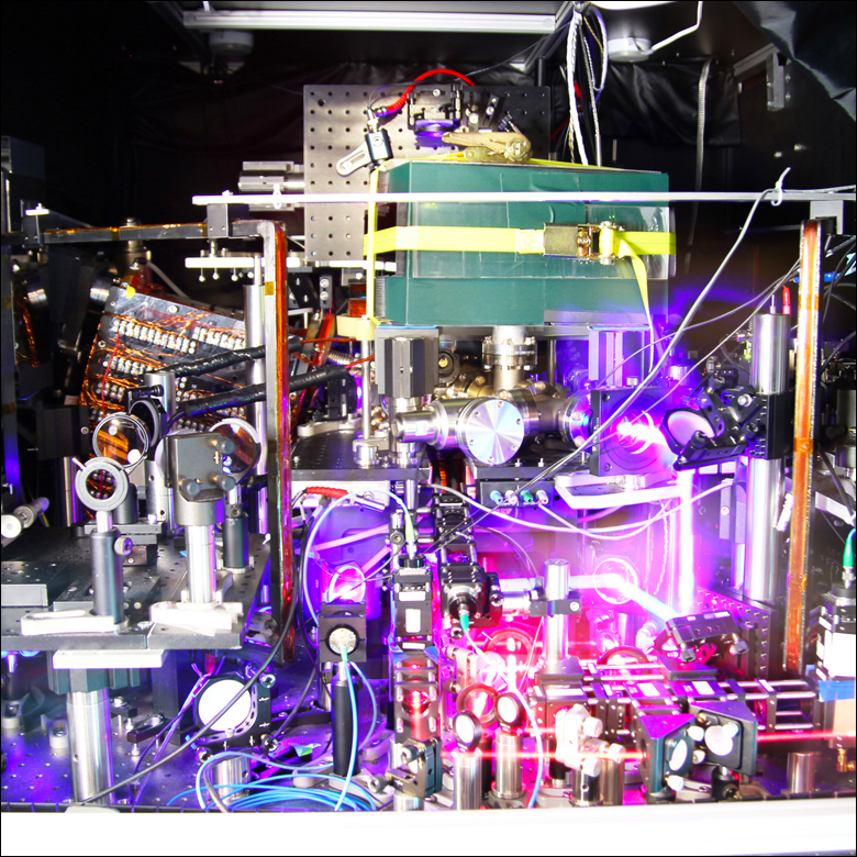
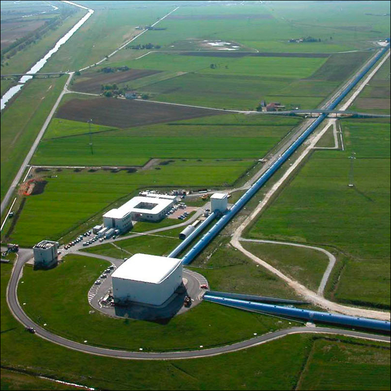
Figure 1: (Left) Photograph of a strontium optical clock constructed by researchers at the University of Colorado and the National Institute of Standards and Technology [2]. (Right) Aerial view of the Virgo gravitational wave observatory [3].
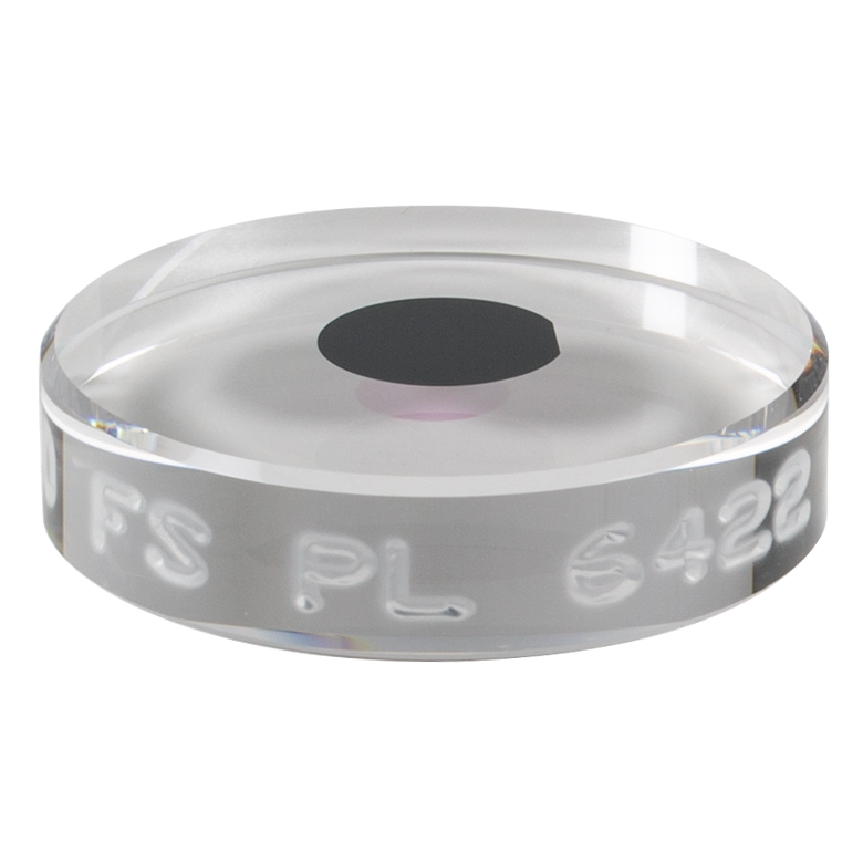
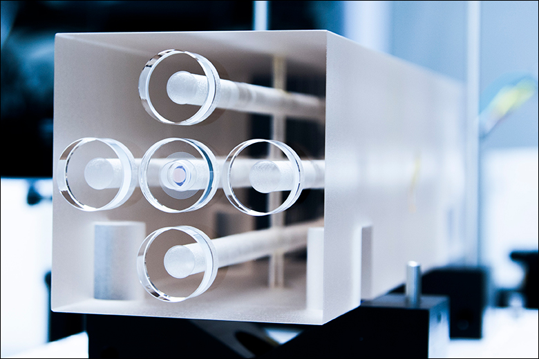
Figure 2: (Left) Photograph of a 1-inch diameter mirror with an 8-mm diameter high reflectance crystalline coating (Item #: XM12P8). (Right) Photograph of an assembled optical cavity with crystalline mirrors attached to the center bore and a number of blank substrates capping the off-center bore holes (reserved for future use).
Optical and Mechanical Losses
Click to Enlarge
Figure 3: Schematic of optical loss mechanisms caused by an optical coating.
Coating optical loss mechanisms consist of transmission (T), scatter (S), and absorption (A), as shown in Figure 3. Collectively, scatter and absorption are known as excess optical losses, and are critical parameters for supermirrors. While transmission is typically a design parameter controlled by the layer structure of interference coatings, excess losses are generally harder to control beyond a minimum level driven by manufacturing and material imperfections. In the case of an optical cavity, the partition of losses between transmission and excess loss determines the usability of the cavity – if excess loss dominates, there is little difference between the on- and off-resonance levels of transmission, leading to poor optical frequency discrimination and poor signal-to-noise. Assuming perfect spatial mode matching of the input beam to the cavity, the fractional amount of power transmitted through the cavity is given by Pt /Pi = T2/(T+S+A)2, where Pt and Pi are the optical powers transmitted and incident on the cavity, respectively.
Critically, the optical cavity transmission rapidly drops to zero when the excess losses are much greater than T (Figure 4). For a given lowest workable value of cavity transmission Pt , the lowest achievable levels of excess loss will dictate the lowest practical value of T, which in turn determines the highest achievable finesse. Therefore, high-quality supermirrors need to be superb both in their low designed transmission value and as-deposited transmission value and in their ability to achieve low excess loss.
Even for identical optical losses (leading to identical finesse and cavity transmission), not all supermirrors are created equal! In applications where the reference cavity length noise arising from the thermal atomic motion in the coating matters (e.g. in the construction of narrow-linewidth lasers with active locking to an optical cavity, or precision displacement sensing as with gravitational wave detectors), the mechanical material properties also become important [4]. Monocrystalline semiconductor materials such as GaAs/AlGaAs exhibit quasi-bulk properties and lower mechanical noise than amorphous, dielectric coatings created from sputtering, as shown in Figure 5. The reduction in elastic losses in these materials, which is quantified by the mechanical loss angle, Φ, the imaginary component of a complex Young’s modulus E(f ) = E0[1+i Φ(f )], is a consequence of the nearly flawless crystal lattice created by molecular beam epitaxy. The resulting >10× reduction in Φ for our crystalline coatings results in a reduction of the frequency-dependent noise power spectral density (NPSD) by a factor of √Φ in a properly designed reference cavity, when compared to amorphous mirror coatings deposited with processes such as ion-beam sputtering [5].
Click to Enlarge
Figure 5: Crystalline mirror coatings exhibit lower mechanical noise than amorphous coatings. [5]
Click to Enlarge
Figure 4: Plot of on-resonance cavity transmission assuming perfect spatial mode matching and identical input and output mirrors. Transmission falls away from unity even for extremely small levels of excess loss.
Cavity Ringdown for Optical Loss Characterization
Click to Enlarge
Figure 7: Plot of finesse against total losses for an optical cavity consisting of two identical mirrors shows that the finesse rapidly falls with losses at the few-ppm level.
Click to Enlarge
Figure 6: In cavity ringdown, the rate at which the intracavity field leaks out from a cavity is dependent on the total optical losses of the coatings.
Precise and accurate determination of the quantities T and S + A presents a difficult measurement challenge due to the small values (typically 10 < T < 5 ppm and S + A < 5 ppm for our crystalline coatings) and dynamic range involved. For example, commercial spectrophotometry systems are relatively widely accessible, but will typically provide accuracies at a 0.3% (3000 ppm) level up to reflectivities of approximately 99.9%. Similarly, ratiometric laser power measurements providing 0.01% (100 ppm) accuracies for reflectivities up to 99.99% fall short for characterization needs of these supermirrors. Technical challenges include source amplitude stability, detector linearity over large ranges of optical inputs, and detection noise.
In 1984, Anderson, et al. [6] described a reflectometer based on a resonant optical cavity comprising high-reflectivity end mirrors in order to convert an amplitude measurement into a pure time-delay measurement by exploiting the finite speed of light. When a pulse of incident light reaches the output mirror, a fraction equal to the transmission T is outcoupled and a fraction R is reflected back into the cavity (see Figure 6). On the second round-trip, the same fraction T of this now-reduced incident power is again out-coupled. This ratiometric progression of loss per round trip of the cavity leads to an exponential decay of the transmitted optical power with time constant τ. Critically, this technique is impervious to source amplitude fluctuations, and less sensitive to detector linearity, detection noise, and dynamic range limitations compared to other measurement techniques.
With a measured value of τ and the known cavity length, L, the total optical loss (T + S + A) of each supermirror is given by T + S + A = L / (cτ), where c is the speed of light. From the conservation of energy, the total loss and reflectivity are connected by 1 - R = T + S + A.
Commonly, the cavity finesse F = cπτ / L is also used to describe the optical loss of a reference cavity. For a simple linear optical cavity consisting of two mirrors, the finesse is related to the reflectivity of each mirror by F = π√R / (1 - R). Figure 7 shows that few-ppm levels of deviation in losses lead to large changes in finesse for high-finesse cavities (e.g., above 200 000), making control over these losses extremely important for these applications.
Further decomposition of the losses into the component T, S, and A values is realized as follows:
- T is a design parameter that can be determined to ~1 ppm precision in our crystalline coatings with knowledge of the indices of refraction of the substrate and coating materials, coupled with measurements of the as-grown layer thicknesses via X-ray diffraction and, optionally, scanning electron microscopy.
- A can be directly and independently measured using photothermal common-path interferometry.
- S is the remaining unknown that can simply be extracted arithmetically, or alternatively directly measured via scatterometry.
Click to Enlarge
Figure 9: The cavity ring-down setup is used to precisely measure the characteristic exponential decay of the signal. [4]
TCS Measurement Protocol and Coating Loss Mapping Service
The total optical loss of every supermirror we ship is measured using a custom-built cavity ring-down system [7]. Figure 8 shows a simplified operational diagram of this setup. Diode lasers are directly coupled—without optical isolation—into a linear cavity formed from a pair of crystalline supermirrors. This arrangement greatly simplifies the system by removing the need for active laser stabilization. The retroreflection of the cavity input coupler forms an extended cavity diode laser and narrows the laser linewidth (as shown in the inset graph in Figure 8). The narrowed linewidth increases the in-coupled optical power by pulling the laser close to the center wavelength of the coating, where the composite laser and external cavity typically has the lowest loss. Irises ensure that the sampled points fall within a radius of 1.5 mm of the center of the mirror substrate. An InGaAs camera (owing to the infrared nature of our mirrors) is used to align the supermirrors and excite the fundamental TEM00 mode. A fast InGaAs photodiode detects the transmitted optical power and a digital delay generator [8] modulates the laser diode current to zero when the transmitted power exceeds a threshold voltage and triggers data acquisition of a single ring-down transient.
Click to Enlarge
Figure 8: Custom-built cavity ringdown system for testing crystalline supermirrors [4]. The bare signal is the bare laser spectrum measured by the OSA when the cavity is blocked, while the feedback signal is the measurement of the laser exposed to retroreflection from the cavity.

Click to Enlarge
Figure 10: Example of a map of excess optical loss taken across the central region of a crystalline mirror.
Typical ring-down signals and the residuals generated from a least-squares fit to the model y=ae(-t/τ)+b are shown in Figure 9. Additionally, the average of 50 consecutive ring-downs and their fit residuals are displayed, and there are no signs of non-exponential behavior at our highest levels of signal-to-noise ratio.
By mounting the supermirrors on motorized mounts with four degrees of freedom (two angular and two translational), the optical loss from each coating (including curved mirrors) can be spatially mapped. Figure 10 shows an example of a discarded coating exhibiting a constellation of defect sites that was mapped in this way. Complete correlation of the high optical loss regions to visible coating defects was established by comparison to differential interference contrast microscopy. (See Reference [7] for a more complete discussion on the measurement technique and mapping system.)
While the development of this scanning cavity ringdown apparatus was initially developed for internal process development, we can now offer coating loss mapping as a service for mirrors operating at 1064 nm, 1156 nm, 1397 nm, 1550 nm, and 1572 nm.
Case Study: A Compact 50 mm Cubic Optical Reference Cavity for Fieldable Applications
Optical reference cavities intended for use outside the laboratory in mobile experiments, or those onboard satellites in space, need to be compact in size due to payload limits. However, shorter reference cavities suffer two disadvantages. First, the sensitivity of optical frequency discrimination will decrease because the cavity linewidth increases for given mirror reflectivities. Second, the coating thermal noise becomes a greater contributor to the noise budget for decreasing cavity length.
Optical Cavity Noise Comparison Tool
We partnered with Wolfram® to create a web application that allows you to directly compare the optical cavity noise performance between our crystalline supermirror coatings and conventional ion-beam sputtered (IBS) coatings for a variety of cavity design parameters. The application may be accessed by clicking the link below:
Optical Cavity Noise Comparison for Crystalline
and Amorphous Coatings.
To address optical frequency sensitivity of such a compact reference cavity, we manufacture mirrors with a target and measured T of ~4 ppm. These mirrors are mapped to verify sufficiently uniform optical performance, with excess losses below 3 ppm, yielding a finesse in excess of 400 000 at 1397 nm in vacuum at room temperature. The inferred cavity transmission in this case is then close to Pt / Pi = 33%, assuming perfect spatial mode matching, and the inferred cavity full-width-at-half-maximum linewidth is 7.5 kHz.
After passing coating qualification, the mirrors are assembled into an optical cavity by contacting them to a 5-cm-long ultralow-expansion (ULE) glass spacer. The assembled cavity finesse is measured once again to confirm that the fully assembled cavity meets specifications and no dust or other fouling has degraded the mirrors during assembly. Should a cavity not meet specifications, the combined in-house mirror fabrication, cavity assembly and ringdown measurement capabilities allows rapid repair/replacement iterations as needed.
The assembly of the completed cavity ends with the contacting of ULE compensation rings to the back side of the mirrors. In terms of the theoretical noise performance, this cavity (including contributions from the ULE spacer, fused silica substrates, and crystalline coatings) has a Brownian-limited frequency noise PSD of 3.6 × 10⁻³ Hz2/Hz (at 1 Hz) corresponding to an Allan deviation flicker floor of 3.3×10⁻¹⁶ at 1 s of averaging. In this implementation, the fraction of the Brownian thermal noise contributed by the spacer, substrate, and coating is 5.5%, 64.5%, and 30% respectively. In contrast, a comparable cavity with IBS coatings and having the same optical quality would yield a Brownian-limited frequency noise PSD of 2.5×10⁻² Hz2/Hz (at 1 Hz) corresponding to an Allan deviation flicker floor of 8.7×10⁻¹⁶ at 1 s of averaging. With amorphous mirrors, the fraction of the Brownian thermal noise due to the spacer, substrate, and coating is 0.8%, 9.4%, and 89.8% respectively. As can clearly be seen, the dielectric coatings are the key noise source in such a high-performance reference cavity and our semiconductor supermirrors can significantly reduce the limiting thermal noise.
Conclusion
Supermirrors are indispensable for modern optical metrology and find use in increasingly high-performance optical cavities from the cm to km length scales. Improvements in coating technology are now pushing the ultimate limits of optical performance, with T + S + A at the <5 ppm level, enabling finesse values well in excess of 500 000. At the same time, the use of ultrahigh purity and low-mechanical-loss monocrystalline-semiconductor-based interference coatings are enabling order-of-magnitude reductions in elastic losses. The ability to fabricate mirrors with simultaneously excellent optical and mechanical properties through the use of crystalline coatings has led to substantial progress beyond fundamental limitations in the length stability of cutting-edge optical resonators.
In the development of our semiconductor supermirror technology, we have focused on the production of crystalline mirrors with ever increasing reflectance. This has been achieved through continuous improvements in our epitaxial growth and substrate-transfer coating processes, enabling the minimization of excess optical losses. To progress in these efforts, we have overcome challenges related to the verification of the optical properties of this new class of low-optical-loss elements, with a key advancement being the development and demonstration of a novel spatial scanning ringdown system. Our in-house characterization capabilities are unmatched and allow us to confidently deliver mirrors that meet our customers’ stringent requirements. Ultimately, these mirrors, when built into a cavity and incorporated in purpose-built metrological systems, are advancing the state-of-the art in timekeeping and spatial measurement processes, impacting fields such as quantum optics, the study of quantum many body systems, ultrasensitive trace gas detection, and ultimately cosmology and astrophysics via the development of low-loss and low-noise reflective test masses for next-generation gravitational wave detectors.
References
- A. E. Siegman. (1986). Lasers. University Science Books
- Photo Credit: Ye Group and Baxley/JILA
- Photo Credit: The Virgo Collaboration
- Harry, G., Bodiya, T., & DeSalvo, R. (Eds.). (2012). Optical Coatings and Thermal Noise in Precision Measurement. Cambridge: Cambridge University Press
- Cole GD, Zhang W, Martin MJ, Ye J, and Aspelmeyer M. "Tenfold reduction of Brownian noise in high-reflectivity optical coatings." Nature Photonics. 2013 August; 7: 644-650.
- Anderson DZ, Frisch JC, and Masser CS. "Mirror reflectometer based on optical cavity decay time." Applied Optics. April 15, 1984; 23: 1238-1245.
- Truong GW, Winkler G, Zederbauer T, Bachmann D, Heu P, Follman D, White ME, Heckl OH, and Cole GD. "Near-infrared scanning cavity ringdown for optical loss characterization of supermirrors." Optics Express. June 24, 2019; 27: 19141-19149.
- https://github.com/geedubs/teensytrigger
| Posted Comments: | |
| No Comments Posted |