 Products Home
Langevin Transducers for Ultrasonic Welding
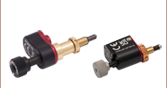
PKT40B
15 kHz, 500 W,
Ø60 mm x 163 mm
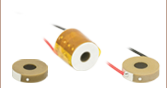
PKT40A
20 kHz, 700 W,
Ø50 mm x 117 mm
- Designed to Produce Ultrasonic Vibrations for Thermoplastic Welding
- Hard PZT Material Chips Bolted Together in Metal Housing
- Resonant Frequencies of 15 kHz or 20 kHz
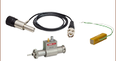
Application Idea
Ultrasonic Welding Stack Comprised of PKT40A Langevin Transducer (Left),
Connector (Center), and Sonotrode/Horn (Right)


Please Wait
| Webpage Features | |
|---|---|
| Clicking this icon opens a window containing item-specific specifications and mechanical drawings. | |
Features
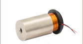
- Langevin Transducers Comprised of Piezo Chips in Metal Housing for Ultrasonic Welding
- Piezo Chips Designed to Produce Resonant Vibrations
- Drive Voltage Range of 0 - 5 kV
- Resonant Piezo Chips Also Available Separately
Thorlabs offers Langevin transducers with integrated piezo ring chips designed for use in ultrasonic welding. The PKT40A Langevin Transducer with four PA40ND5 chips provides a 20 kHz resonant frequency as the work frequency and an instantaneous power of 700 W. The PKT40B Langevin Transducer with four PA40TM chips provides a 15 kHz resonant frequency as the work frequency and an instantaneous power of 500 W.
The hard PZT material in these Langevin transducers can be driven at up to 5 kV, but operation above 3 kV may create an arc in the air. Protective measures such as silicone oil should be applied when the voltage is above 3 kV; for a complete list of specifications, see the blue icons below. We recommend driving clamped chips or transducers using a sine wave at the work frequency with a voltage of 0 - 5 kV. The graphs of impedance and phase angle, accessible by clicking on the blue icons below, illustrate the sharp phase angle slope around the resonant frequency of the devices. The sharp phase angle slope is useful for tracking the resonant frequency which may shift during operation due to temperature changes.
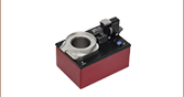
Each transducer contains a discrete stack of four ring chips clamped with a bolt between two metal housings. Each stack has copper foil electrodes; the positive pole only contacts the piezo chips, while the negative pole is also connected to the metal housing, which should be connected to the negative pole of the driver or grounded. For more details, see the Operation tab. The assembly bolt at the top is tightened to a specific torque and its thread is locked; it should not be loosened or removed. The PKT40A and PKT40B transducers can be mounted via the holes in the base which have M18 x 2.0 and M20 x 1.5 taps, respectively.
| Item #a | Info | Resonant Frequencyb | Powerc | Drive Voltage Ranged | Capacitancee | Dimensions | Joint Bolt |
|---|---|---|---|---|---|---|---|
| PKT40A | 20 kHz | 700 W | 0 - 5 kV | 10.0 nF ± 15% | Diameter: 50.0 ± 1 mm Width: 68.0 ± 1 mm Height: 117.0 ± 1 mm |
M18 x 2.0 | |
| PKT40B | 15 kHz | 500 W | 9.0 nF ± 15% | Diameter: 60.0 ± 1 mm Width: 90.0 ± 1 mm Height: 163.0 ± 1 mm |
M20 x 1.5 |
Langevin Transducer Operation Notes
Electrical Considerations
The electrode that is in contact with the metal housing should be grounded and the other electrode should be positively biased. The absolute maximum voltage is 5 kV. Exceeding 5 kV will decrease the device’s lifespan and may cause mechanical failure. Reverse biasing the device may cause mechanical failure. Operating the device above 3 kV may create an arc in the air. Protective measures such as silicone oil should be applied when the voltage is above 3 kV.
When soldering wires to the copper foil electrodes, use a soldering iron at a temperature no greater than 370 °C (700 °F) for a maximum of 2 seconds per spot, soldering to the middle of the electrode.
Electrical Shock and Discharge Caution
During operation, high voltage is applied to the piezo and electrodes; do not touch the device by hand or with conductive materials to avoid injury or short circuit.
After being driven, the piezo is fully charged. Directly connecting the positive and negative electrodes may result in a spark and/or device failure. It is recommended to discharge using a resistor (>1 kΩ) between the positive and negative electrodes.
Attaching Devices to the Transducer
Loads should only be attached to the tapped hole in the base of the metal housing. The metal housing of the transducer can be held or clamped.
Caution: When operating at the resonant frequency, high voltages will be applied to the transducer which will generate high frequency forces as well as heat. Do not touch any part of the device to avoid risk of injury from electric discharge, vibration, or heat. When operated for extended periods, cooling the piezo chips and metal components by rapid air flow is recommended.
Storage Instructions
- Do not store the device at temperatures above 100 °C.
- Do not store the device in humid environments. The relative humidity (RH) should be less than 40%.
- Do not immerse the device in organic solvents.
- Do not use the device around combustible gases or liquids.
| Posted Comments: | |
Nina Brown
(posted 2023-06-22 11:25:59.843) ThorLabs sells 15kHz and 20kHz Langevin Transducers. My research group at the University of Chicago works on acoustic levitation, and we use frequencies near 40kHz to levitate microscale particles and examine fluid interactions. One of the reasons we use those higher frequencies is because they're well outside the audible range. While we have been able to find 40kHz transducers, it has been difficult to find ones that are well-documented/characterized. I am wondering if ThorLabs is considering making Langevin Transducers for other frequencies.
Best,
Nina Brown jpolaris
(posted 2023-06-27 07:25:10.0) Thank you for contacting Thorlabs. We will reach out to you directly to discuss the possibility of offering a customized Langevin Transducer. Jonathan Tinker
(posted 2021-07-22 09:25:39.287) Just as an FYI, I ordered a pair of the PKT4A transducers and the mounting holes in the bottom were not M16 as described. They ended up being M18x2.00, which is a much harder bolt size to source. It would be beneficial to update the part description to reflect that so future customers won't have the difficulty I did. YLohia
(posted 2021-07-26 02:00:05.0) Thank you for your feedback! We are currently revising the mounting hole description. Please accept our apologies for any inconvenience caused, and thank you for pointing this out. |
Ultrasonic Welding |