 Products Home
Fiber Photometry Overview
- Custom Fiber Photometry Equipment Built to Order
- Fiber-Coupled, LED, and Laser Light Sources
- Same-Day Shipping for In-Stock Components
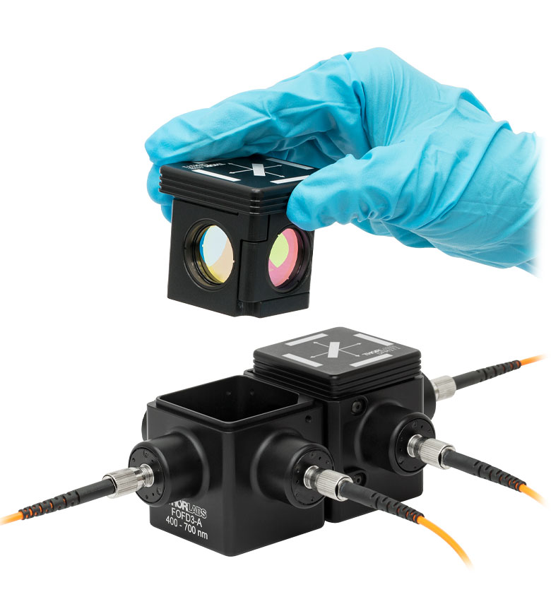
FOFD3-A
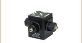
Kinematic Multimode Fiber Optic Fiber Cube
MF525-39
GFP Emission Filter
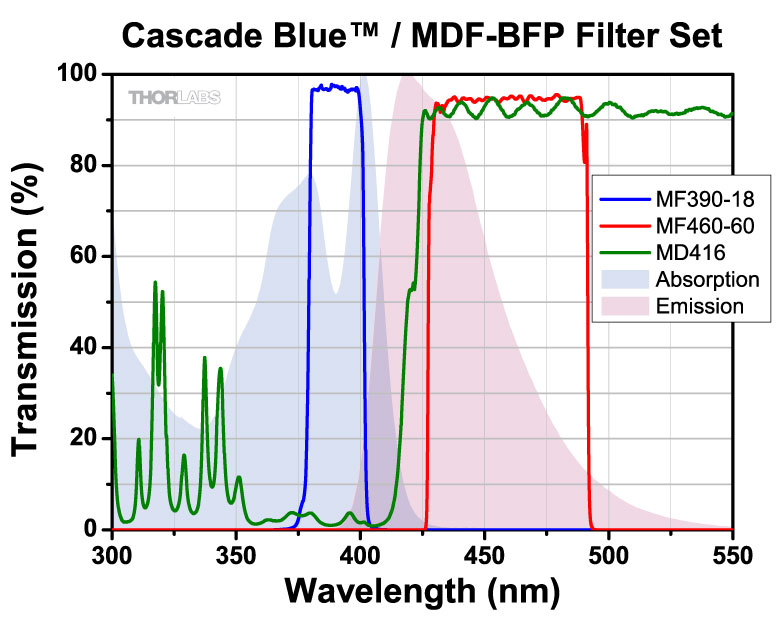
MD416
BFP Dichroic Filter
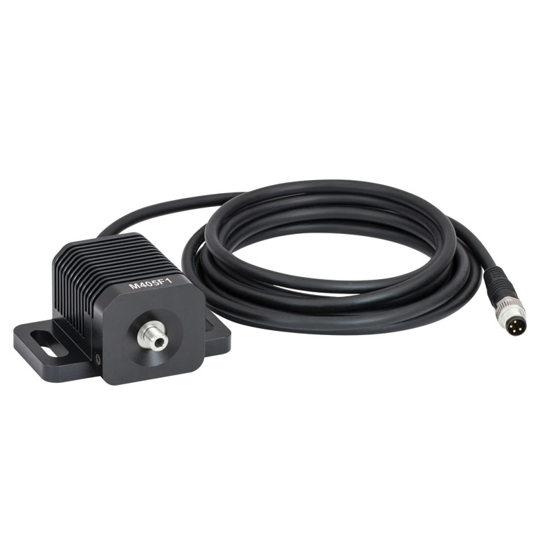
M405F1
405 nm Fiber-Coupled LED
CFM15L20
Fiber Optic Cannula, Stainless Steel Ferrule
CFMC54L10
Fiber Optic Cannula, Ceramic Ferrule
MAF1L1
Ø400 µm Core, 0.50 NA FC/PC Low‑Autofluorescence Patch Cable


Please Wait
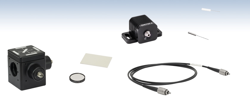
Thorlabs Fiber Photometry System Components
- Thorlabs' Fiber Photometry Equipment is Used Extensively in Leading Labs
- Custom Equipment Built to Order
- Complete System Including Fiber Optic Cannulae, Fiber Patch Cables, and Light Sources
- Stock Components (Same Day Shipping)
- Fiber Optic Cannulae
- Stereotaxic Cannula Holders and Adapter Arms
- Cannula Implant Guides
- Fiber Optic Patch Cables
- Fiber-Coupled LEDs
- Modulated LED Drivers
- High Bandwidth Detectors
- Low Autofluorescence Patch Cables
- Rotary Joints
- Lightweight Patch Cables
- Fiber Optic Interconnects and Mating Sleeves
- Fluorescence Filters and Dichroic Mirrors
- Multimode Fiber Optic Filter Cubes
- LED and Laser Light Sources
- Next-Day Availability for Custom Patch Cable Orders Placed Before 2 PM EST
Thorlabs offers a full line of equipment for in vivo stimulation, including implantable fiber optic cannulae, fiber optic patch cables, rotary joints, and LED and laser light sources. We are also well equipped to provide custom fiber photometry packages, including fiber-coupled light sources and custom-made cannulae. Please contact Tech Support for individual assistance regarding fiber photometry equipment selection.
The equipment needed for photometry is very similar to that used in an optogenetics experiment; however, due to the nature of fluorescence imaging, care must be taken in selecting the correct fiber optic components throughout the system to optimize signal intensity. In addition to the abovementioned common optogenetic tools, filters and dichroics with mounting hardware and multimode collimators used for fiber-to-free-space coupling are needed to filter and split the outgoing excitation signals from the incoming fluorescence signals. The collimators and rotary joints use an achromatic design to ensure that insertion loss is consistent throughout the visible wavelength spectrum that pertains to fiber photometry.
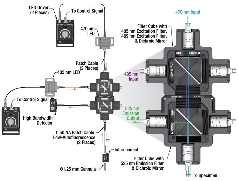
Interactive Fiber Photometry System Schematic
Click on the components for more details about our optogenetics line of products. Contact Tech Support for more information about our expanding line of fiber photometry products.
Introduction to Fiber Photometry
Click to Enlarge
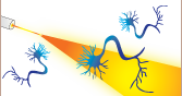
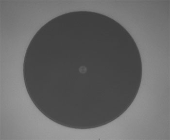
An example of fluorescence data showing neural activity in a GCaMP transgenic sample. GCaMP fluoresces only when bound to a calcium ion, providing insight into calcium dynamics and neuronal response patterns.
Fiber photometry, a technique related to optogenetics, provides detailed insight into the activity and behavior of neuronal populations. This technique stimulates neurons with light and measures fluorescence signals that correspond to calcium dynamics. By detecting changes in the fluorescence intensity from a genetically encoded calcium indicator (GECI), calcium dynamics related to activities and patterns in neural circuits can be measured in real time.
The technique has helped in developing treatments for neurological diseases and brain-related traumatic injuries. Its use of light offers many advantages over other methods of neuromodulation, including a temporal resolution on the order of milliseconds, closely matching natural neuronal activity; and the stimulation of multiple neuron sets independently through the use of different wavelengths.
In fiber photometry, data is collected by analyzing the change in fluorescence (ΔF) relative to an initial baseline fluorescence (F) and observing a change in signal that corresponds to a calcium transient (ΔF/F). These indicators are typically based on fluorophores like GFP, RFP, tdTomato, mCherry, etc., of which GCaMP is the most common example. GCaMP contains Green Fluorescent Protein (GFP). As such, GCaMP not only exhibits the same fluorescence patterns as standalone GFP, but also provides key insight into calcium dynamics because GCaMP only fluoresces when bound to a calcium ion. In neurons, calcium ions regulate several important processes, including neurotransmitter release and membrane excitability. Therefore, GCaMP fluorescence is tied directly to neuronal response patterns, as depicted by the graph to the right.
To excite GCaMP in a neuronal population of interest, 470 nm and 405 nm LED sources are used to simultaneously photoexcite the maximum absorption and isosbestic points of the fluorophore, respectively. Each peak on a graph of ΔF/F indicates a neuronal response to an externally applied light stimulus. When using GCaMP as the fluorophore, as is most typical for fiber photometry, the peak specifically indicates when 525 nm fluorescence is emitted, following the simultaneous application of 405 nm and 470 nm inputs.
The main advantage of this excitation scheme is that excitation at the 405 nm isosbestic point will yield calcium-independent fluorescence in contrast to the calcium-dependent fluorescence at 470 nm. By modulating the excitation sources, the two emission signals can be read independently and simultaneously, providing important information about which part of the detected signal can be attributed to real information about behavior as opposed to background noise. This background noise can be generated from the fiber optic cables, interconnects, and cannulae used in the setup. Motion artifacts pose a particular risk because they create sharp features in recordings of ΔF/F that could easily be misunderstood as spikes in calcium activity if the 405 nm isosbestic point excitation is not measured in parallel.
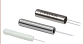
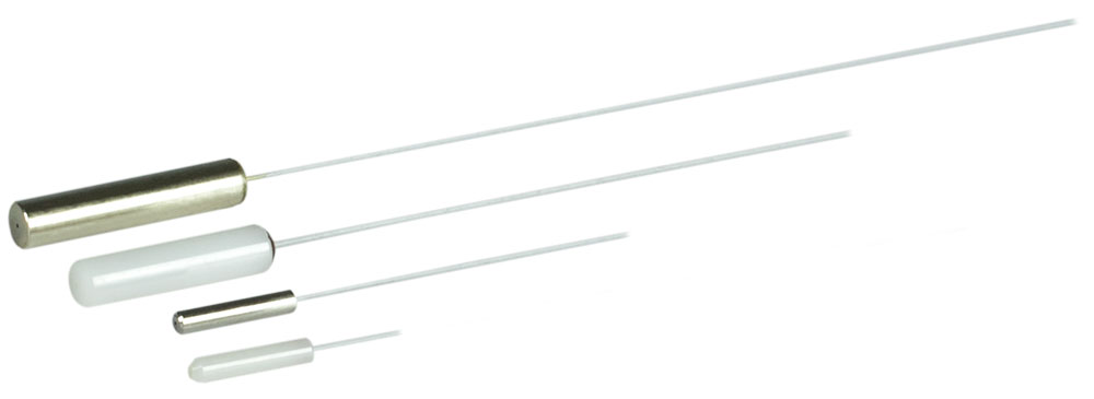
Fiber Optic Cannulae
- Low-Profile Implantable Fiber Optic Cannulae
- Ø1.25 mm and Ø2.5 mm Ceramic and Stainless Steel Ferrules Available
- Ø200 µm, Ø300 µm, and Ø400 µm Multimode Optical Fiber Available
- Precision-Cleaved or Scissor-Cut Fiber End
- Custom Cannula Also Available (see the Custom Cannula Tab)
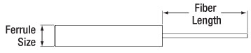
Thorlabs offers stock and custom fiber optic cannulae, which can be surgically mounted to the skull of the specimen using stereotactic guidance. Custom cannulae are available with stainless steel or ceramic ferrules as well as an array of different fiber types, lengths, and end terminations. See the Custom Cannula tab above for details.
For fiber photometry applications, we recommend using Ø400 µm, 0.50 NA optical fiber to maximize signal intensity and minimize autofluorescence intensity. As detailed below, we offer Low Autofluorescence Patch Cables that meet these specifications.

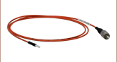
Click to Enlarge
Ferrule Patch Cables are ideal for connection to our Implantable Fiber Optic Cannulae.
Click for Details
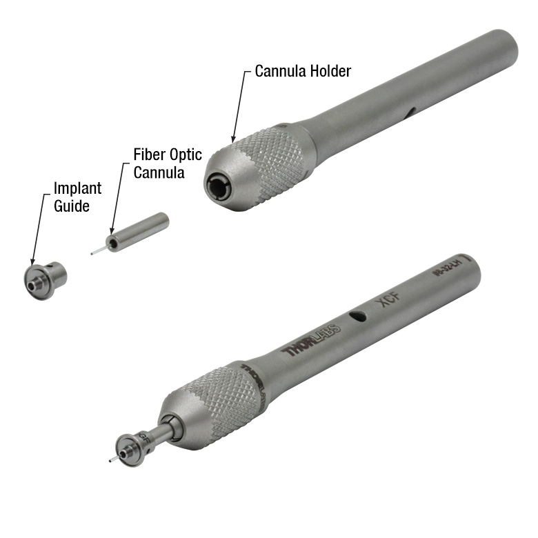
Implant Guide Assembly
Click to Enlarge
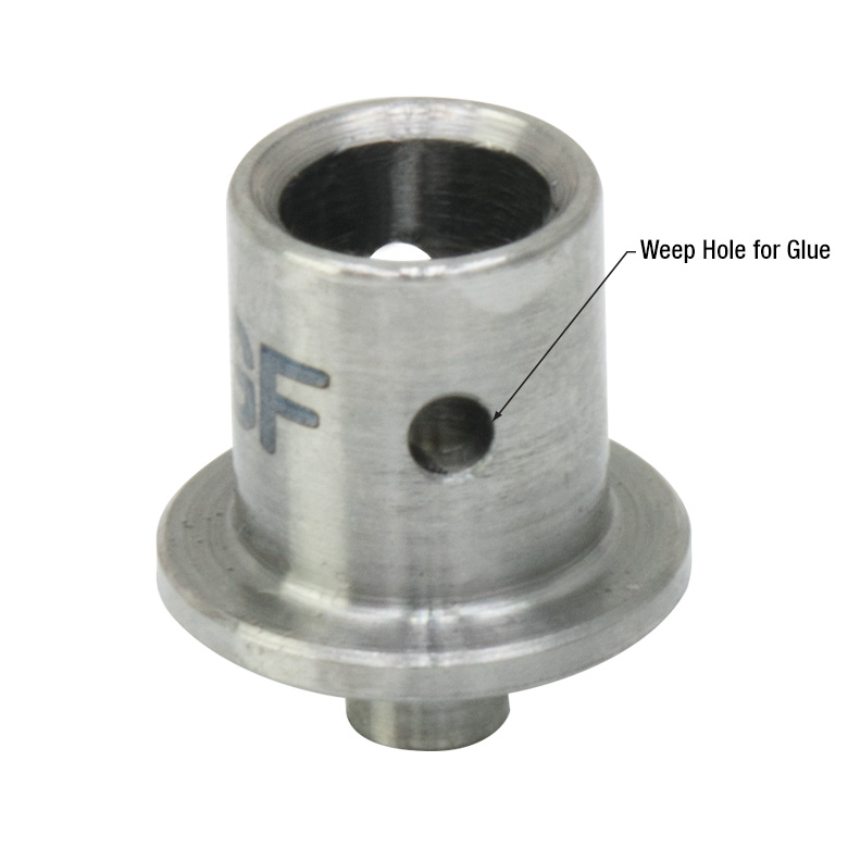
Weep Holes for Epoxy to Escape
Click for Details
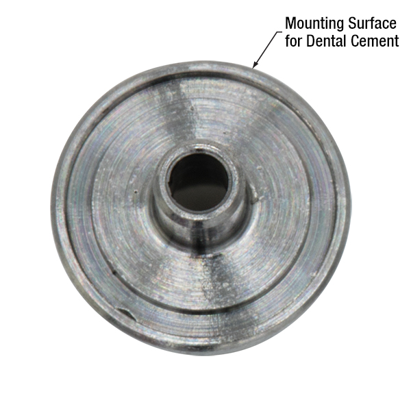
Mounting Surface of OGF Cannula Impant Guide
Cannula Implant Guides
- Improves Adhesion and Stability During Implantation
- Compatible with Ø1.25 mm and Ø2.5 mm Fiber Optic Cannulae with ≥5 mm Length
- Ø3.8 mm (OGL) or Ø5.1 mm (OGF) Mounting Surface with Grooved Ring for Dental Cement
- Lightweight Surgical Titanium Construction (≤0.11 g)
- Weep Holes for Glue and Epoxy to Secure a Cannula
- Compatible with Stereotaxic Cannula Holders
These Cannula Implant Guides are designed to provide guidance and stability for a fiber optic cannula during an implantation procedure. The bottom surface of each implant guide features a roughened surface and circular groove (see image to the right) that increase the surface area available to dental cement and improves adhesion to the specimen. A 1.6 mm long protrusion on the implant guide helps stabilize the guide when implanted. Each implant is constructed using lightweight surgical titanium (≤0.11 g) which can be sterilized prior to use.
For best results when implanting a cannula, the OGL and OGF should be used with a cannula holder and stereotaxic guidance equipment. To affix the cannula within the implant guide, first insert the cannula into the receptacle of the implant guide. Then, add a small amount of cement or epoxy to the cannula via the two Ø0.8 mm weep holes (see image above). Finally, attach the cannula ferrule to an XCL (Ø1.25 mm ferrule) or XCF (Ø2.5 mm ferrule) cannula holder (see image above).
The OGL implant guide is compatible with our standard Ø1.25 mm cannulae (ceramic and stainless steel) and the OGF implant guide is compatible with our standard Ø2.5 mm cannulae (ceramic and stainless steel). When assembled, the length of the protruding fiber is reduced by 1 mm (Item # OGL) or 2 mm (Item # OGF); therefore, these implant guides cannot be used with our 2 mm long cannulae. Additionally, due to the fiber separation distance, the implant guides cannot be used with our dual-core cannulae.
| Common Patch Cables | |||||
|---|---|---|---|---|---|
| Item # Prefix | Core | NA | Wavelength Rangea | Fiber Used | Connector Type |
| M45L | Ø400 µm | 0.50 | 400 to 2200 nm (Low OH) |
FP400ERT | SMA905 to SMA905 |
| M131L | 400 to 2200 nm (High OH) |
FP400URT | FC/PC to SMA905 | ||
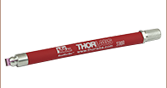
Fiber Optic Patch Cables
Multimode Step Index Patch Cables
- 0.50 Numerical Aperture
- Cables Available for Wavelengths from 250 nm to 2400 nm
- SMA905-to-SMA905 and SMA905-to-FC/PC Cables Available
- Ø3 mm Outer Jacket
- Custom Cables Available
Thorlabs offers multimode step index fiber optic patch cables with SMA905 (straight ferrule) and FC/PC connectors. These cables are ideal for a broad range of wavelengths from 250 nm to 2400 nm.
Each patch cable includes two protective caps that shield the connector ends from dust and other hazards. Additional CAPM Rubber Fiber Caps and CAPSM Metal Threaded Fiber Caps for SMA905-terminated ends are also sold separately. All patch cables on this page are sold from stock with same-day shipping available.
The majority of our 0.50 NA patch cables have orange (Ø3 mm) PVC furcation tubing, while the Ø1500 µm core fibers are packaged in stainless steel jackets. We recommend choosing stainless steel jackets when using fibers with large core diameters (≥Ø1000 µm) or high NAs (≥0.50) in light-sensitive applications, as it is easier for stray ambient light to penetrate the Ø3 mm (Item # FT030) fiber jackets. Alternatively, custom patch cables may be purchased that use our black or stainless steel furcation tubing (e.g., FT030-BK, FT038-BK, FT061PS, and others), in order to minimize stray light entering the fiber.
These cables are not designed for applications that require the fibers to carry high optical powers, as excessive powers can cause the epoxy used in the connectors to experience catastrophic heating. Please see the Damage Threshold tab for detailed information. Thorlabs offers alternate cabling options, in addition to unconnectorized fibers, that are compatible with high optical powers. Links to some options are included in the table below.
We have extensive patch cable capabilities including a large, diverse stock of optical fiber and many different types of fiber connectors. If you do not see a stock cable suitable for your application, please see our Custom Patch Cables webpage to request a cable that meets your specific needs.
| Common Fiber-Coupled LEDs | ||
|---|---|---|
| Item # | M405FP1 | M470F3a |
| Center Wavelength | 405 nm | 470 nm |
| Bandwidth (FWHM) | 12 nm | 20 nm |
| Typical Output Spectrum (Click for Graph) |
||
| Ø200 µm Core Fiber Output (Typ.)b |
7.7 mW | 7.0 mW |
| Ø400 µm Core Fiber Output (Typ.)c |
24.3 mW | 21.8 mW |
| CW Drive Current (Max) | 1.0 A | 1.0 A |
| LED Forward Voltage | 3.45 V | 3.1 V |
| Typical Lifetime | >40 000 Hours | >50 000 Hours |
Fiber-Coupled LEDs and Modulating LED Drivers
Neuron stimulation requires precise temporal control of the output light, typically on the order of millisecond pulses. For in vivo applications, electronic modulation of a fiber-coupled LED may be preferred over using a mechanical shutter or other modulation technique. Fiber-coupled LEDs at common wavelengths for fiber photometry can be seen in the table to the right. In a fiber photometry setup utilizing GCaMP as the fluorophore, a 470 nm LED, such as the previous-generation M470F3, and a 405 nm LED, such as the M405FP1, can be used.
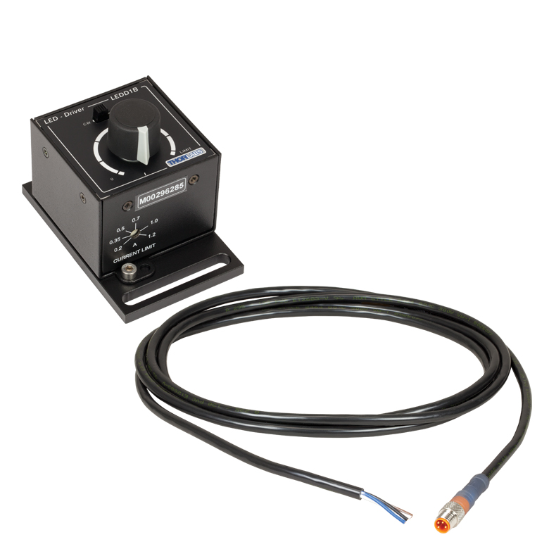
Our fiber-coupled LEDs can be modulated in several ways when used with our LED drivers, such as the LEDD1B. The LEDD1B is designed to drive high-power LEDs with currents up to 1200 mA. It features an adjustable LED current limit to protect the connected LED. The output current can be limited continuously from 200 mA to 1200 mA using the adjuster on the front of the unit, thereby ensuring the output current does not exceed the limit regardless of the other settings or the modulation input voltage. A typical fiber photometry system will require two synchronized drivers that can simultaneously deliver light at both the isosbestic and maximum excitation wavelengths.
This LED Driver has the same compact form factor as other T-Cube modules, and, thus, it integrates well into the platform. It is shipped attached to a removable base plate, which allows the T-Cube to be easily secured to an optical table. The power supply options compatible with the LEDD1B LED Driver can be found here.
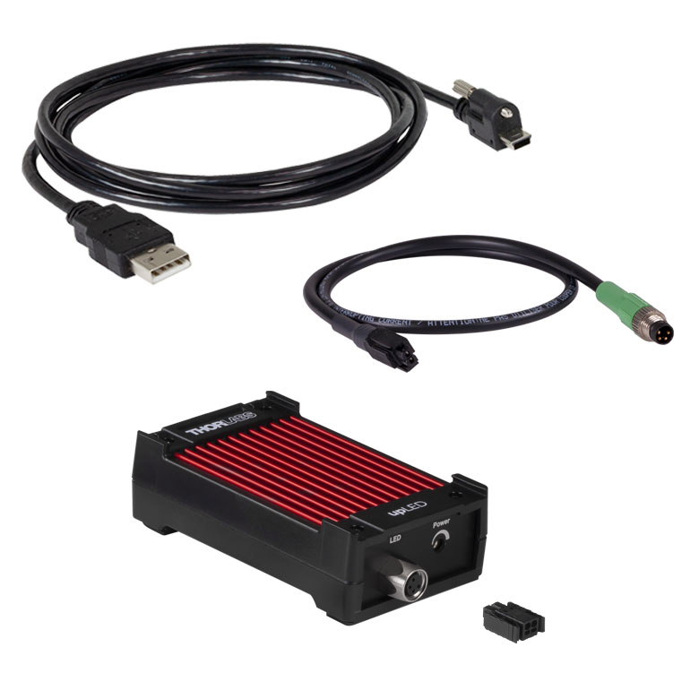
The DC4104 is another driver that is compatible with our fiber-coupled LEDs. This driver is capable of driving up to four of our fiber-coupled LEDs via the DC4100-HUB connector hub with a current range between 0 and 1000 mA. The current of each LED can be set individually by the driver or modulated individually by four external signals through the external modulation cable that comes included with the driver. Please contact Tech Support for additional cables. This driver can be operated through a wheel selector and three buttons on the front panel or remotely via USB 2.0 and the included software package.
Low-Autofluorescence Patch Cables
| Recommended Low-Autofluorescence Patch Cable Fiber Specifications | |
|---|---|
| Item # | MAFxL1 |
| Fiber Type | FP400URT |
| Wavelength Rangea (Click for Plot) |
300 - 1200 nm |
| Core Diameter | 400 ± 8 µm |
| Cladding Diameter | 425 ± 10 μm |
| Coating Diameter | 730 ± 30 μm |
| Numerical Aperture | 0.50 |
| Max Core Offset | 7 µm |
| Minimum Bend Radius (Short Term / Long Term) |
43 mm / 86 mm |
Click to Enlarge
Click Here for Raw Data
Plot comparing the recovery of autofluorescence for a low-autofluorescence (AF) and standard patch cable after photobleaching at 470 nm for 12 hours. A previous-generation M470F3 LED was used for excitation and autofluorescence intensity at 525 nm was measured relative to the output power from the patch cable.
Fluorescence signals are characteristically low, so it is important to maximize signal collection by selecting fibers and cannulae with large numerical apertures and core sizes. In general, Ø400 µm, 0.50 NA core fiber is recommended for adequate signal level, though, to minimize implant size in in vivo experiments, Ø200 µm core fiber can be used as well. Although smaller NAs such 0.39 NA can be used for some optogenetics applications, fibers with a 0.50 NA maximize signal intensity and are therefore recommended for fiber photometry. However, in any high NA fiber, the polymer cladding itself will exhibit some non-zero autofluorescence (AF). On the input side, filters should be used to ensure the input signal is clean, but on the output side, autofluorescence can be easily confused with fluorescence from the genetically encoded calcium indicator (GECI) being studied in the experiment since they are modulated at the same frequency.
To reduce these artifacts, Low-Autofluorescence Patch Cables should be used. These cables are manufactured with components and epoxies that reduce the emitted autofluorescence in the visible spectrum and should be photobleached before use to further minimize noise (see the graph below). This reduction makes these patch cables suitable for fiber photometry applications where high sensitivity is required to measure the changes in fluorescence that indicate neural activity within a specimen. As shown in the schematic above, low-autofluorescence cables are most important in the signal collection path of the fiber photometry system. The design of these patch cables is based on testing of the autofluorescent properties of our patch cable components, such as the bare fiber, ferrule types, and epoxies.
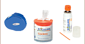
Each patch cable is 1 m long and incorporates a Ø400 µm, 0.50 NA multimode fiber (Item # FP400URT) and is available with three connector configurations. One end is equipped with an FC/PC connector, while the other is equipped with an FC/PC connector, Ø1.25 mm stainless steel ferrule, or a Ø2.5 mm stainless steel ferrule. Black jacketing along the cable minimizes light leakage. Each patch cable includes two protective caps that shield the ferrule ends from dust and other hazards when not in use. Additional plastic, metal, or threaded caps for the connector and ferrule ends are sold separately. If the fiber ends become dirty from use, we offer a selection of inspection tools, as well as fiber optic cleaning products. Similar to our standard optogenetics patch cables, the patch cables with a ferrule end can be mated to a fiber optic cannula using an interconnect or mating sleeve; see the selection guide for compatible products.
We can custom fabricate cables, including armored cable for protection from specimen damage and fan-out cables for incorporating multiple light sources into one fiber optic implant. If you do not see a stock cable suitable for your application, please see our Custom Patch Cables webpage to request a cable that meets your specific needs.

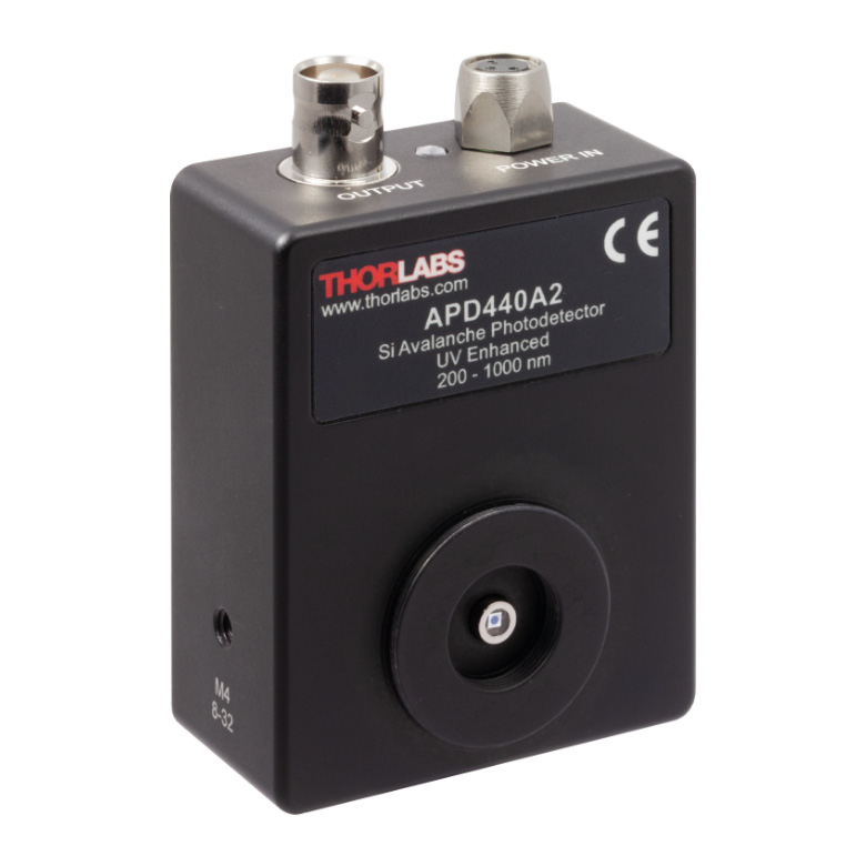
Click to Enlarge
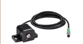
The APD440A2 Avalanche Detector is recommended for fiber photometry applications.
High-Bandwidth Detectors
- Continuously Variable Gain
- Internal SM05 and External SM1 Threads Accept Most Fiber Adapters, Lens Tubes, and Other Components
- Power Supply Included
Thorlabs offers Avalanche Photodetectors (APD) for use in fiber optics systems. These devices feature a variable gain that can be controlled by a knob on the right side of the housing. SM1 threads are ideally matched with our internally SM1 threaded fiber adapters, such as S120-FC2 and S120-SMA, since they create a light-tight path that allows the fiber tip to be brought as close as possible to the detector element.
APDs provide the amplification and low noise-equivalent power (NEP) necessary to recover fiber photometry signals, which can be faint. With care taken, an index matching gel may be used to bring the fiber tip into optical contact with the window on the APD. For fiber photometry applications, we recommend the APD440A2. The 100 kHz bandwidth of this photodetector easily captures events at the millisecond time scales that are characteristic of transient fiber photometry signals. We also offer a range of high-pass electrical filters that can be matched to the repetition rate of your experiment.
Click to Enlarge
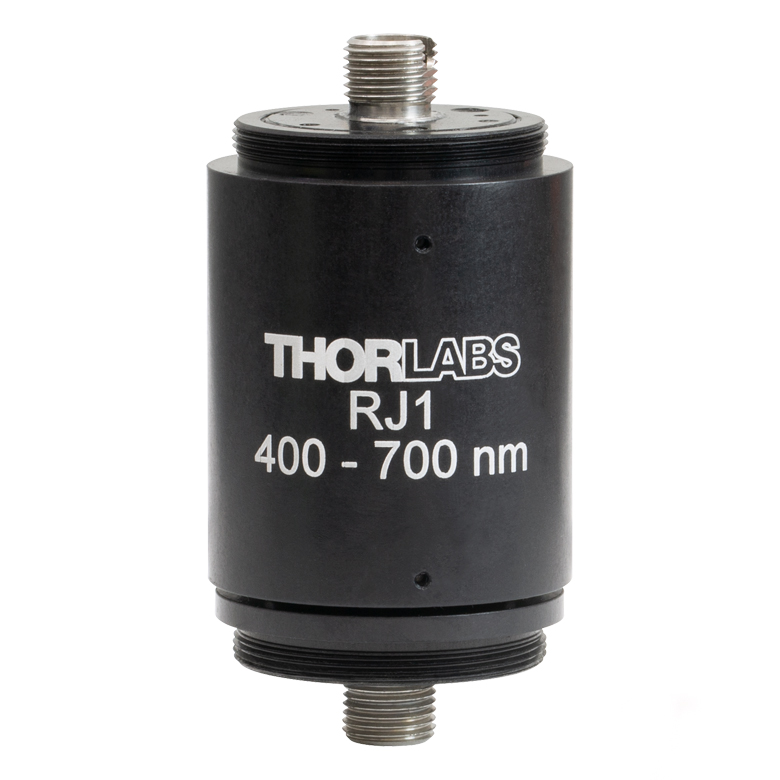
The RJ1 rotary joint has terminated ends and accepts a wide variety of FC/PC patch cables.
1x1 Rotary Joint for FC/PC Multimode Patch Cables
- Rotary Joint Protects Against Fiber Damage Caused by Moving Specimen
- Consistent Performance Over 400 - 700 nm Wavelength Range
- Low Transmission Variation During Rotation
- Recommended for ≥Ø200 µm Core, 0.22 to 0.50 NA Patch Cables
- Tested and Designed for Use with a Multimode Laser or Fiber-Coupled LED
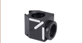
Rotary Joint Commutator
For optogenetics applications and processes that utilize the same materials, such as fiber photometry, the intensity and stability of light that reaches a specimen is determined by how the transmission through a rotary joint changes with rotation. This can also be affected by the core diameter and NA of the connected patch cables, as mentioned previously, as well as by the wavelength and beam divergence of the light sources. When measuring fluorescence from a moving specimen, a fiber optic rotary joint can be used to ensure that the cables do not twist or get tangled, which would potentially damage the fiber optic components.
The collimators and RJ1 rotary joints are designed specifically for use with high NA fibers and use an achromatic design to ensure that insertion loss is consistent throughout the visible wavelength spectrum that pertains to fiber photometry. The selection of the filters and dichroics will depend upon the specific GECI being studied, with 470 nm (gCaMP) and 565 nm (rCaMP) being common examples.
The RJ1 rotary joint commutator has been shown not to add any fluorescence and has minimal rotational variation, which is critical when working with low signal levels. The achromatic design of the RJ1 ensures that insertion loss and rotational variation is very similar throughout the visible wavelength spectrum (400-700 nm), so again the isosbestic point can be used to differentiate motion artifacts from rotation from real calcium transients. The pigtailed rotary joints have higher rotational variation and are therefore not recommended for fiber photometry.
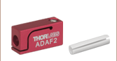
Interconnect and Mating Sleeves
- Ceramic Mating Sleeves for Ø1.25 mm or Ø2.5 mm Bare Ferrules (Sold Individually or in Packs of 5)
- Quick-Release Interconnect for Mating Ø1.25 mm or Ø2.5 mm Ferrule Patch Cables to Cannulae
- Compatible with Stainless Steel and Ceramic (Zirconia) Ferrules
Thorlabs offers interconnects and mating sleeves for making connections between our line of optogenetics patch cables and fiber optic cannulae. These ferrule mating components provide low-loss coupling and are compatible with both stainless steel and ceramic (zirconia) ferrules. Interconnects are designed to facilitate easy connections and disconnections from an implanted cannula, requiring >80% less force to disconnect compared to mating sleeves. On the other hand, mating sleeves are preferred for very lightweight (~0.18 g), low-profile connections between a patch cable and cannula.
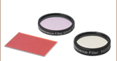
Excitation and emission filters are marked with an arrow that shows the recommended direction of light propagation.
Dichroic filters are marked on the side with the dichroic coating. Light should be incident on this side for best performance.
Fluorescence Imaging Filters and Dichroics
- Excitation, Emission, and Dichroic Filters for Fluorescence Imaging
- >90% Transmission over Desired Wavelength Band
- Sharp Cutoff (T < 0.001%) Outside the Transmission Band
- Matched Filter Sets Designed to Target Many Common Fluorophores:
- BFP
- CFP
- WGFP
- GFP- FITC
- Alexa Fluor® 488
- YFP
- tdTomato- TRITC
- Texas Red
- mCherry
- Cyanine (CY3.5) - Excitation and Emission Filters are Mounted in Black-Anodized Housings
- Dichroic Filters are Unmounted
- Filter Sets are Available at a Savings Over Individual Filter Prices
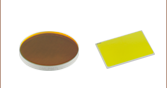
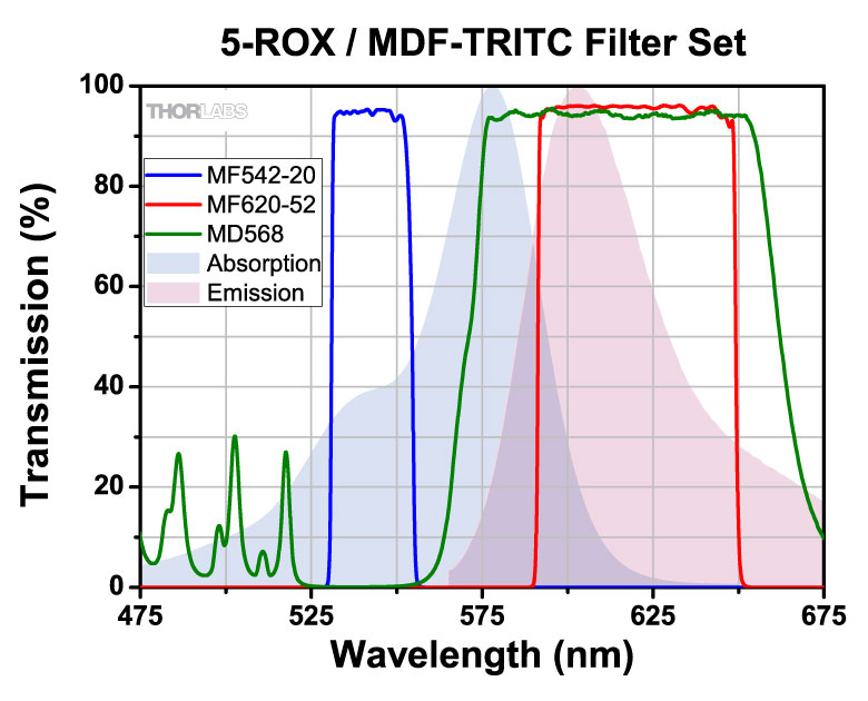
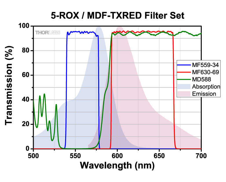
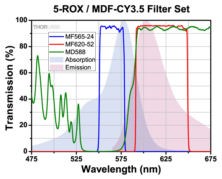
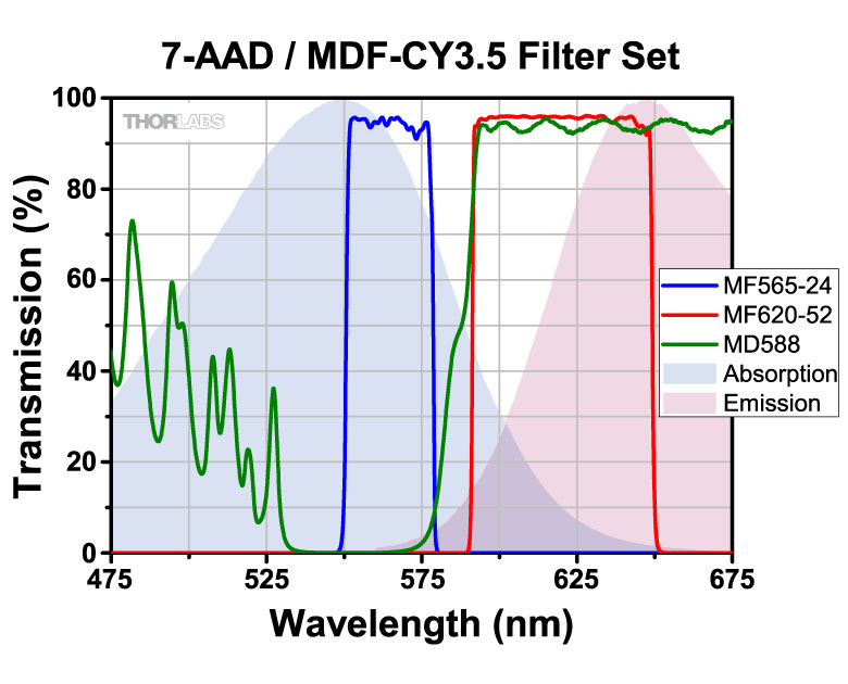
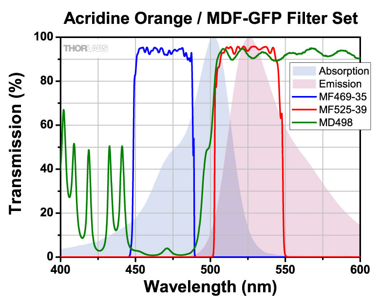
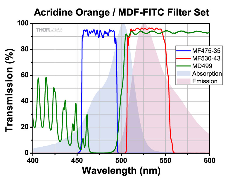
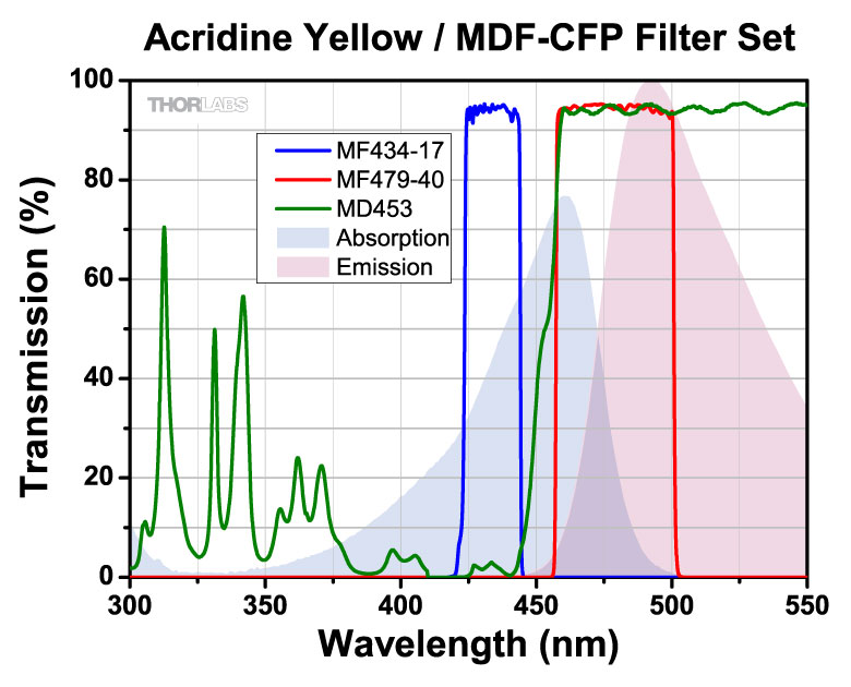
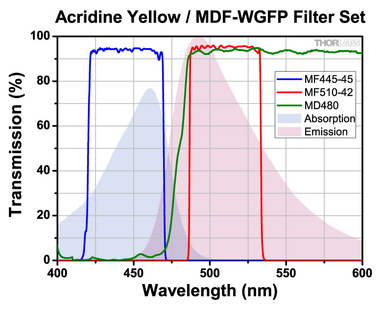
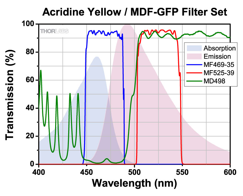
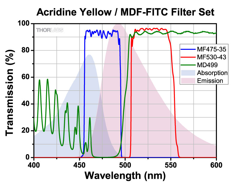
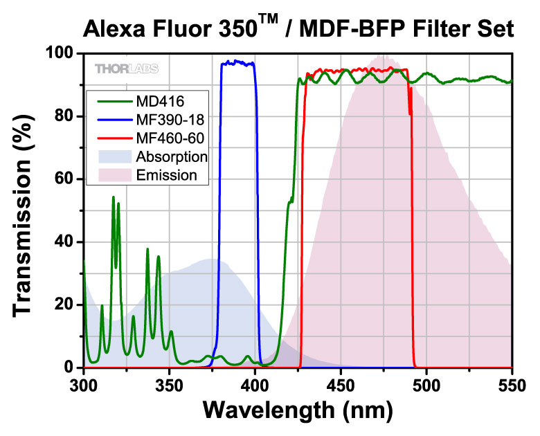
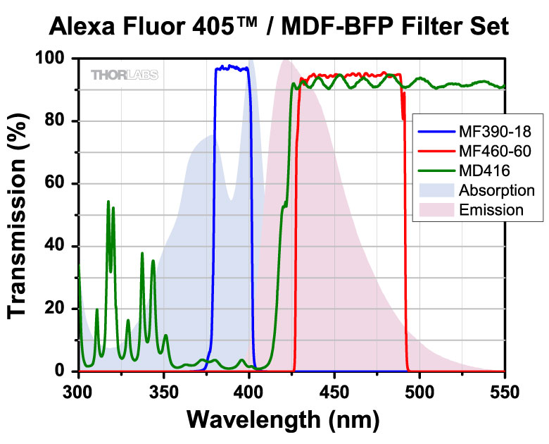
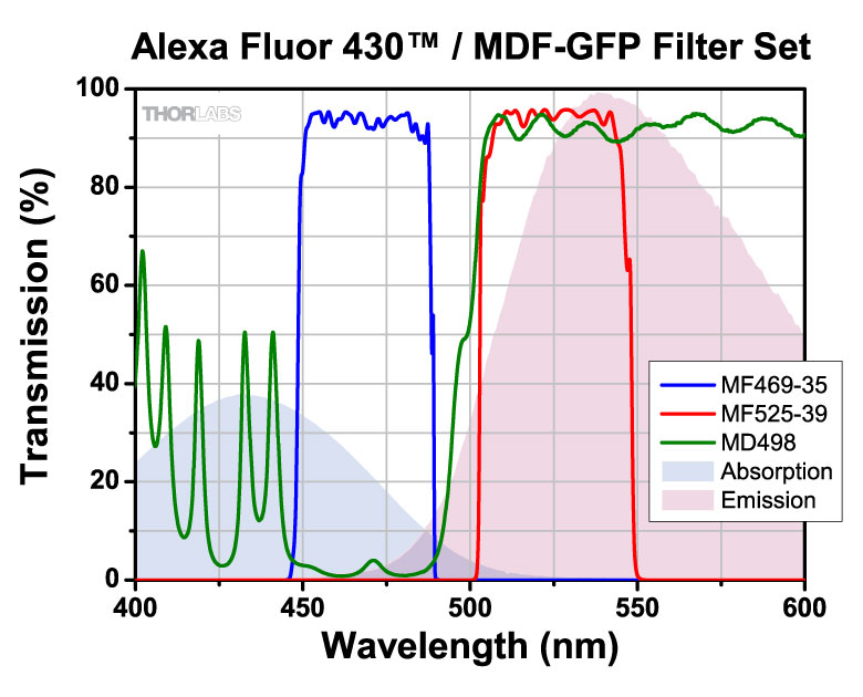
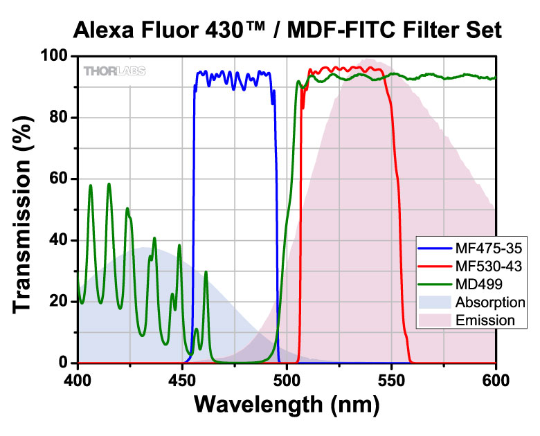
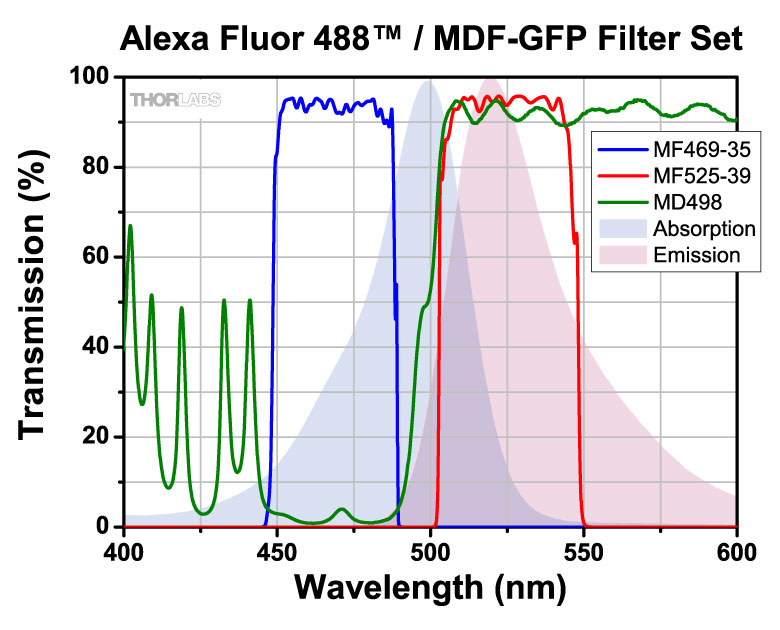
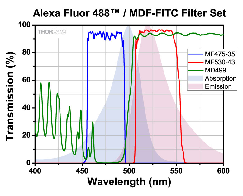
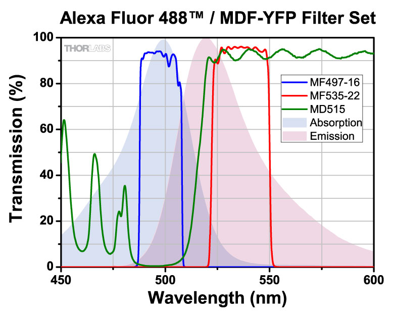
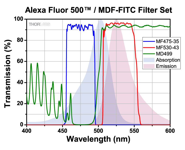
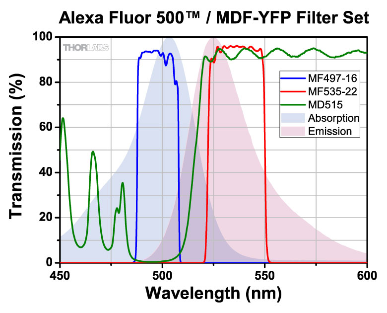
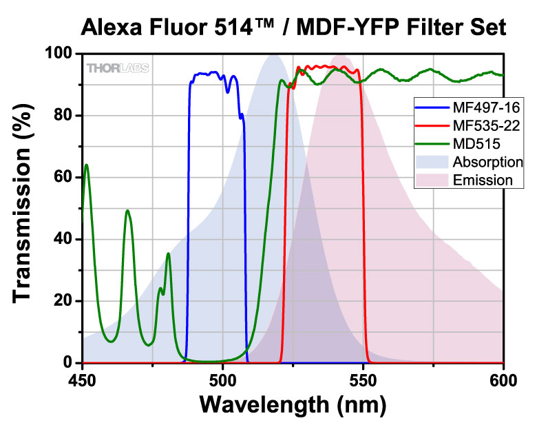
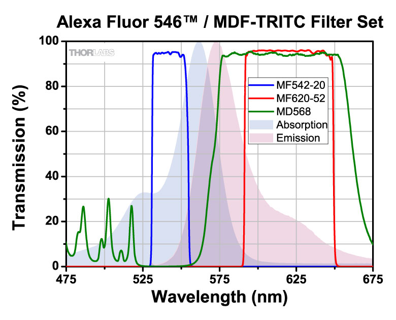
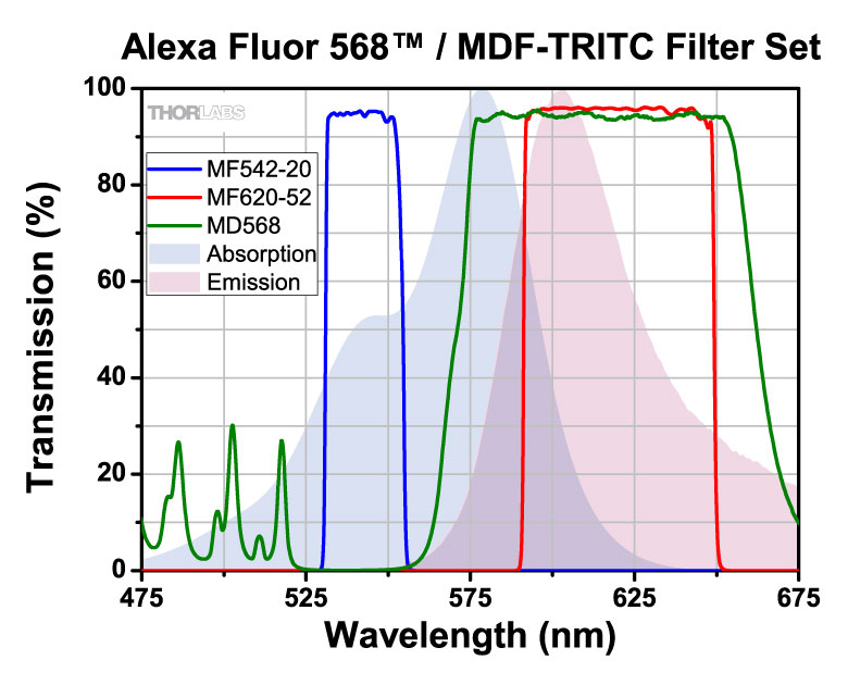
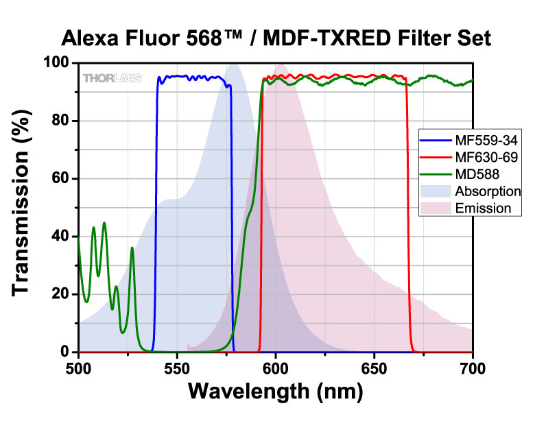
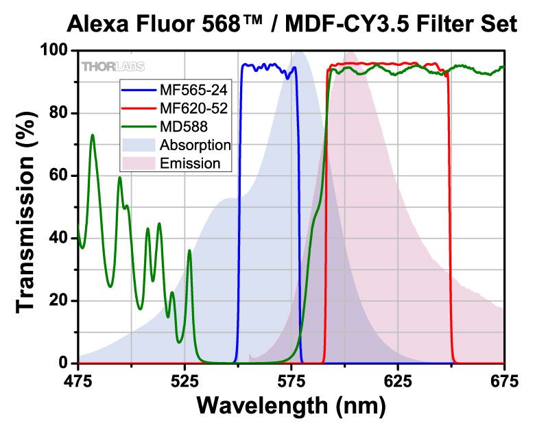
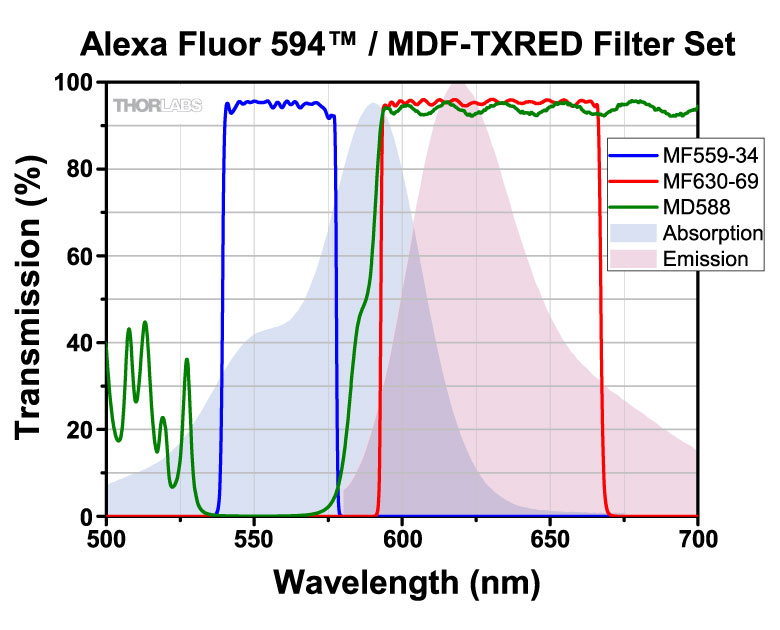
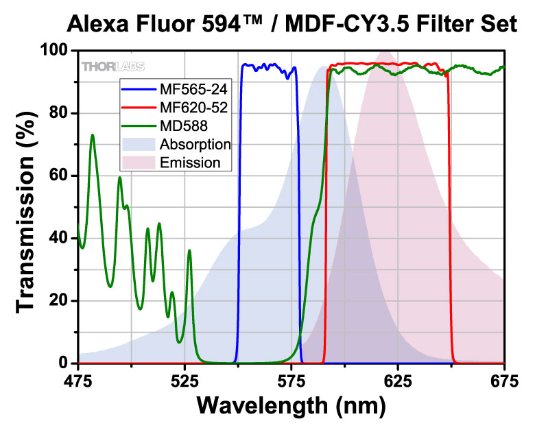
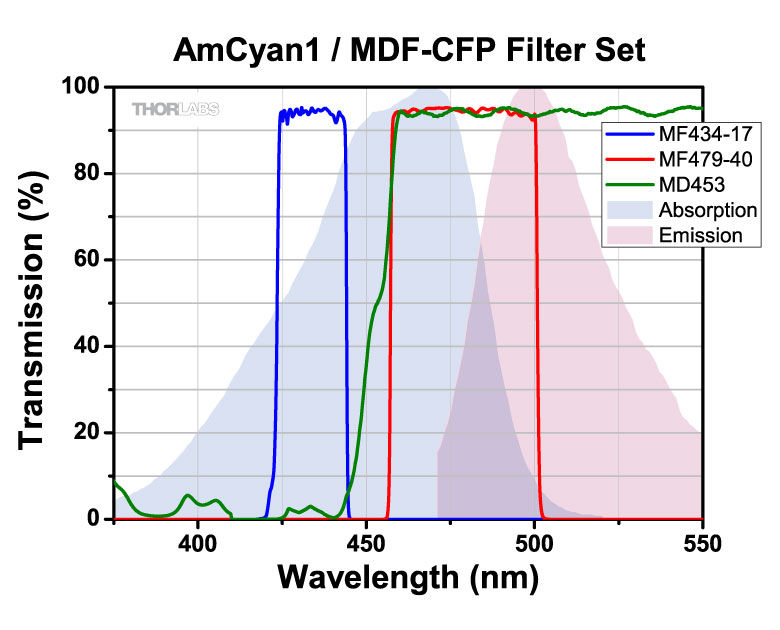
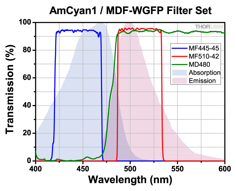
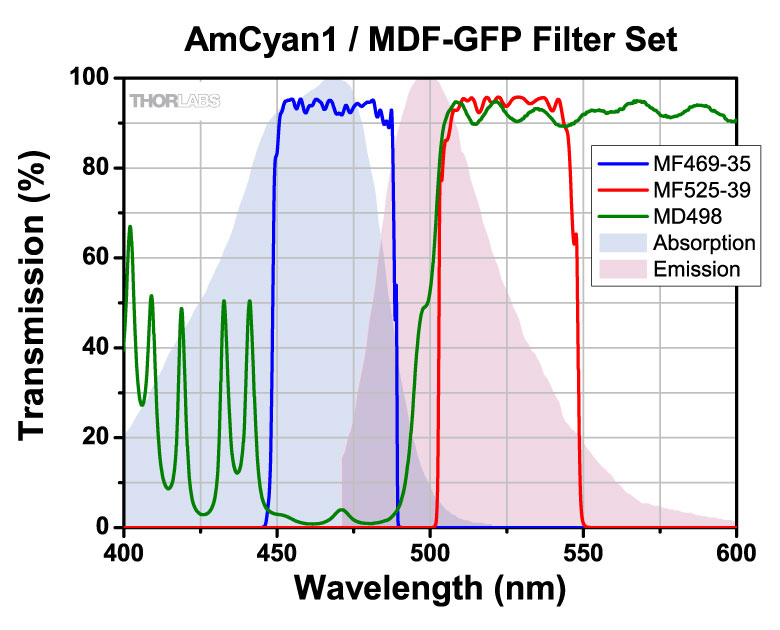
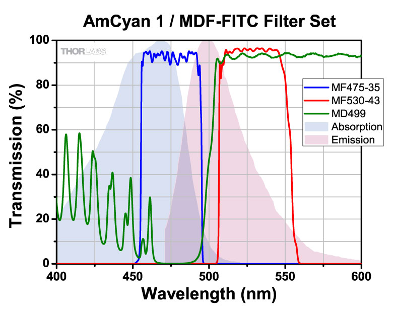
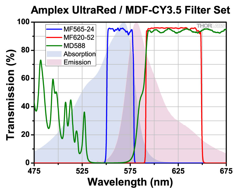
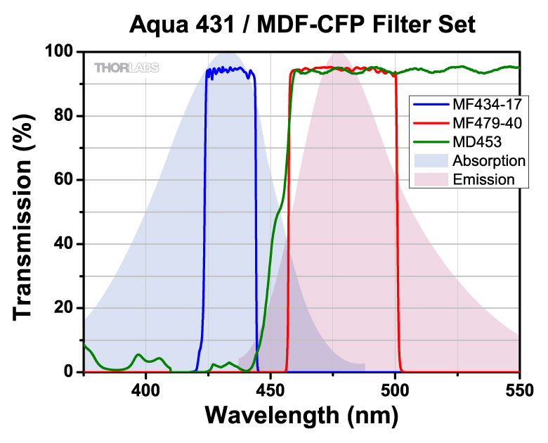
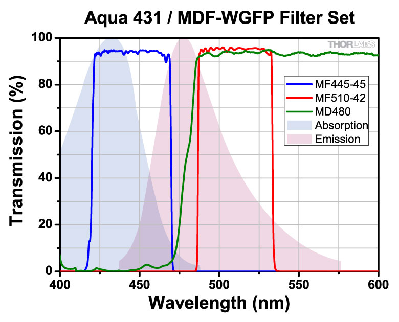
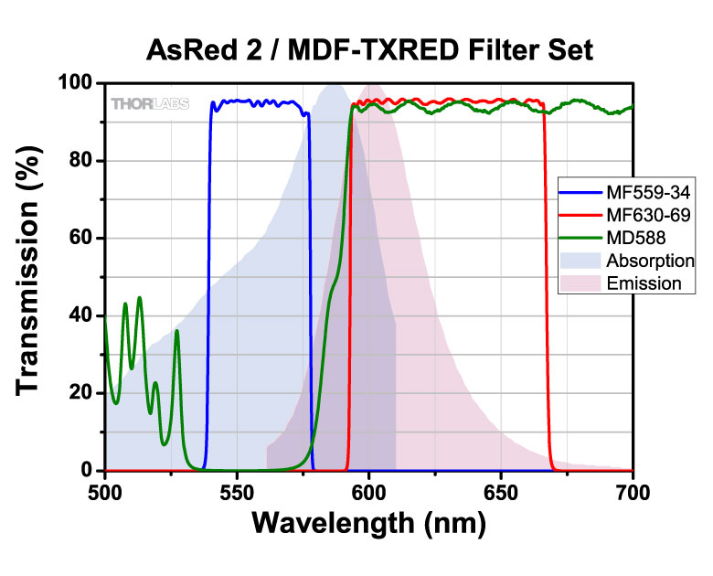
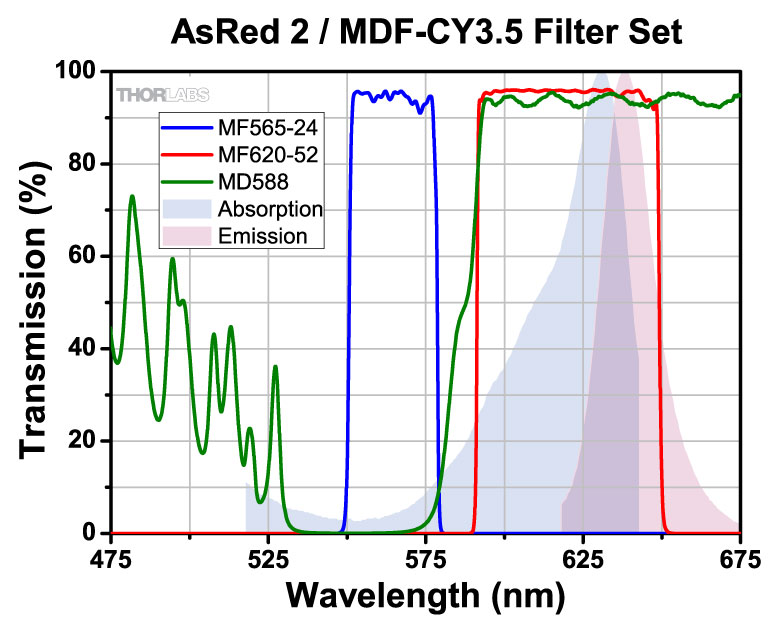
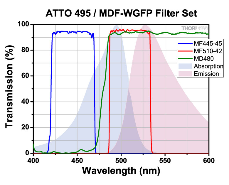
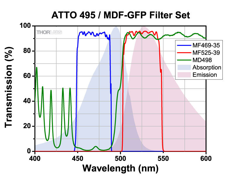
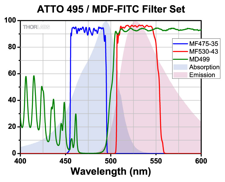
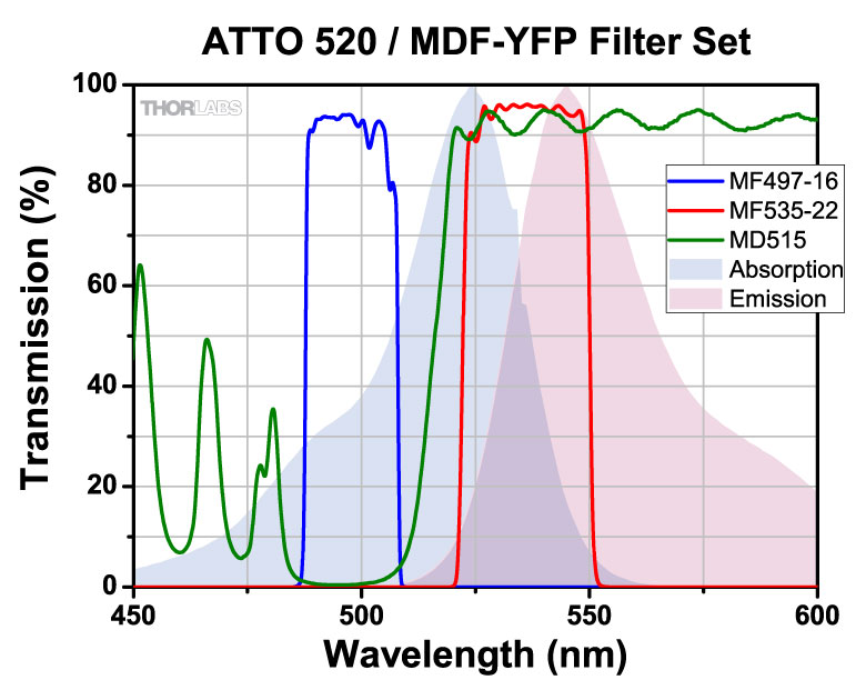
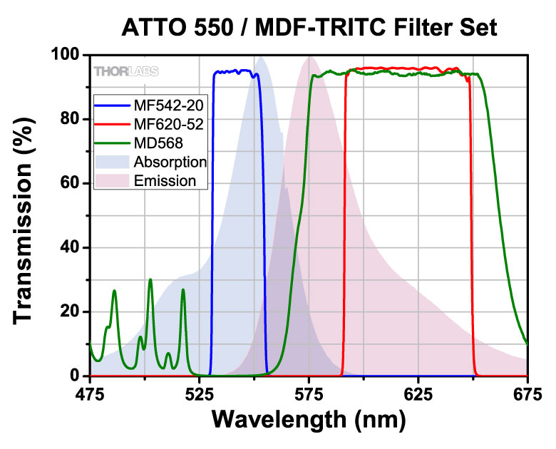
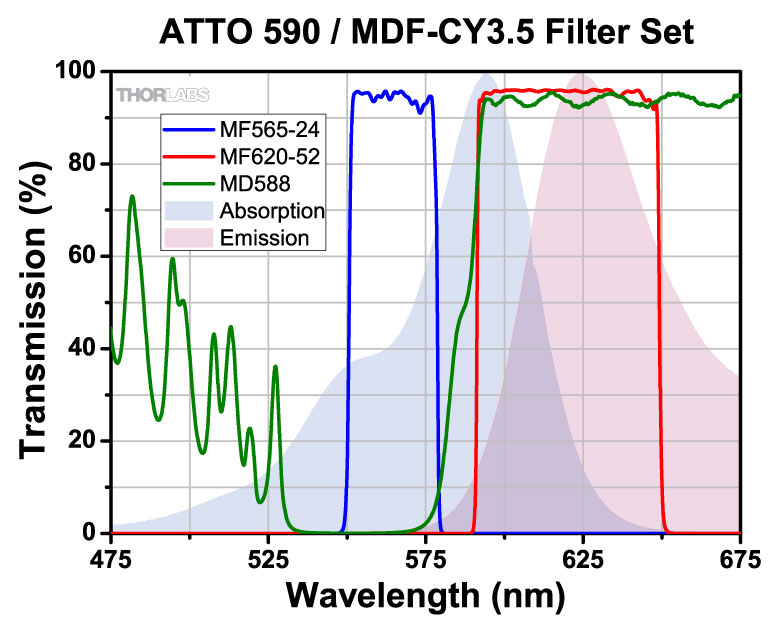
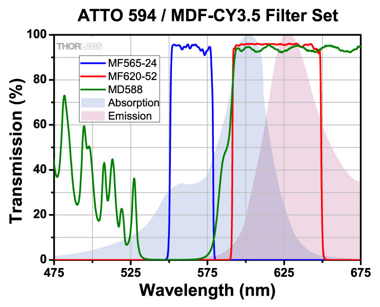
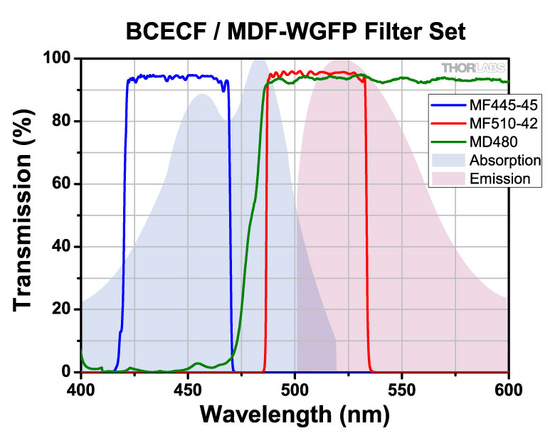
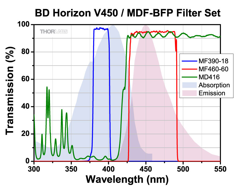
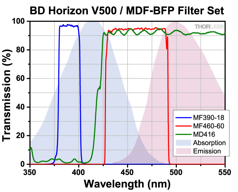
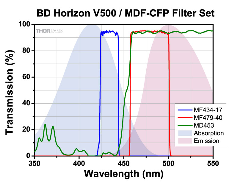
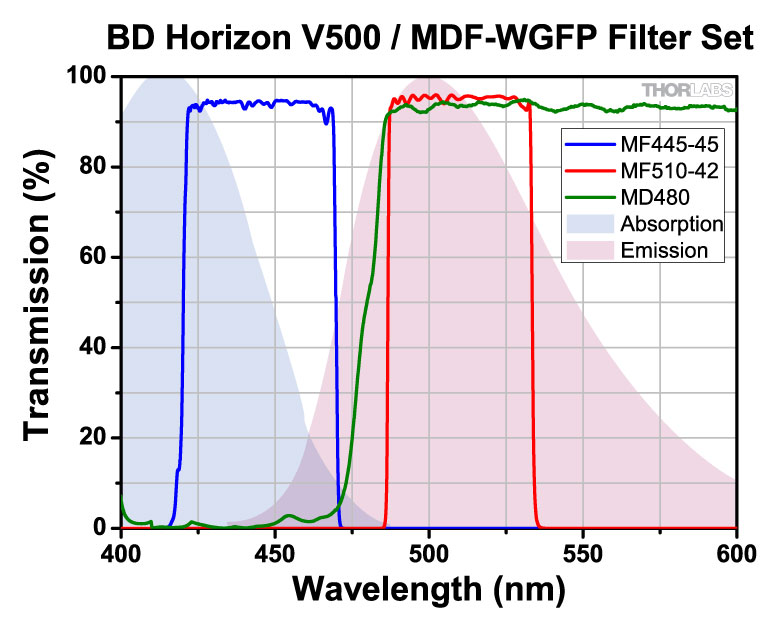
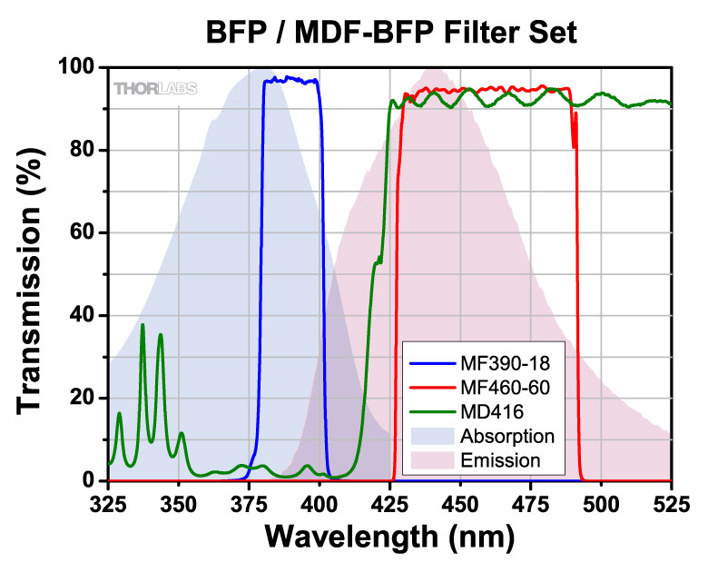
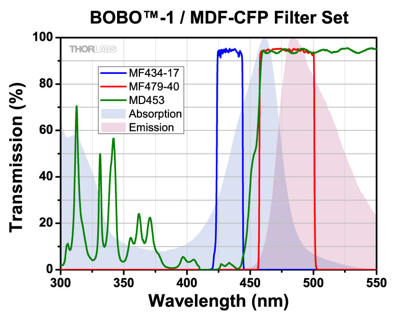
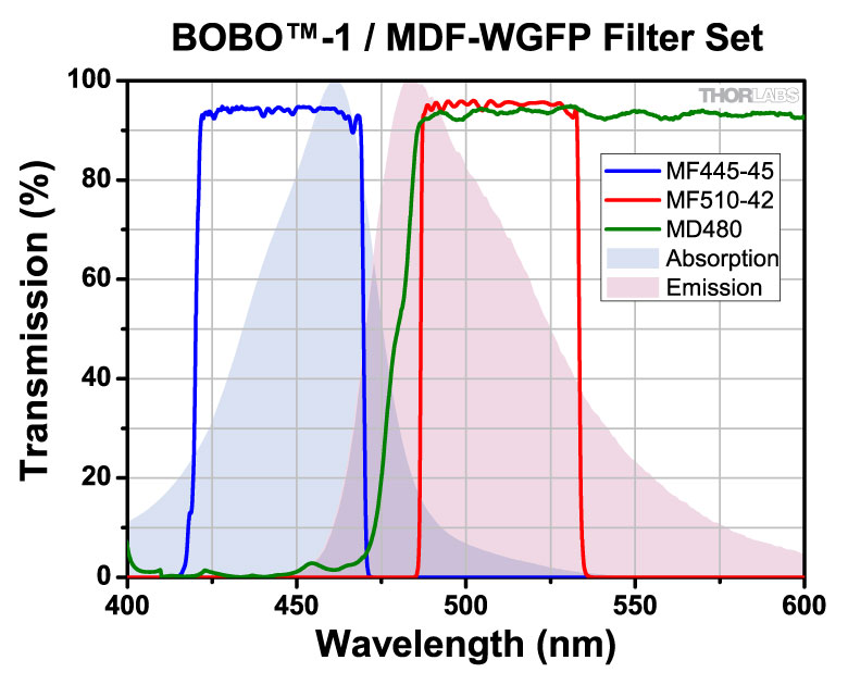
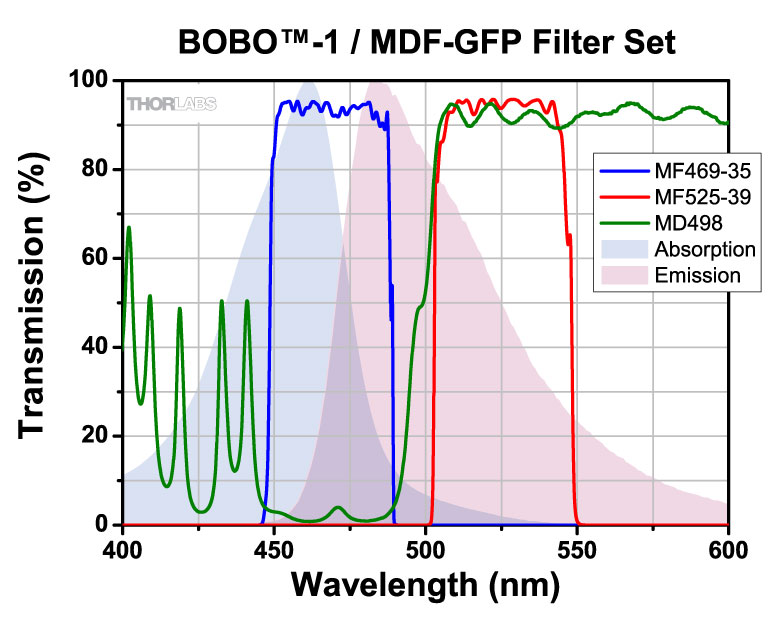
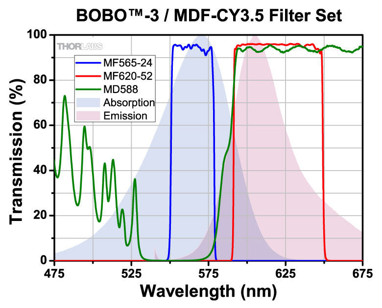
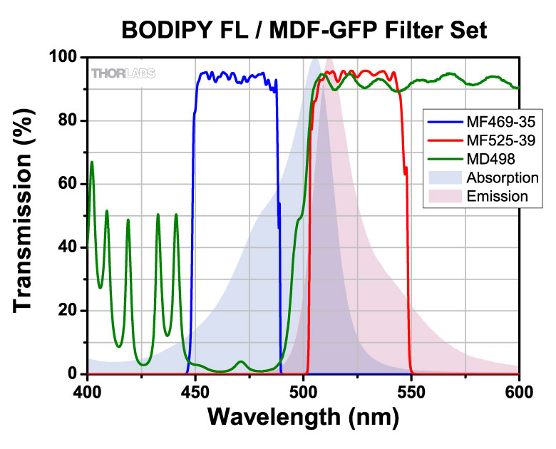
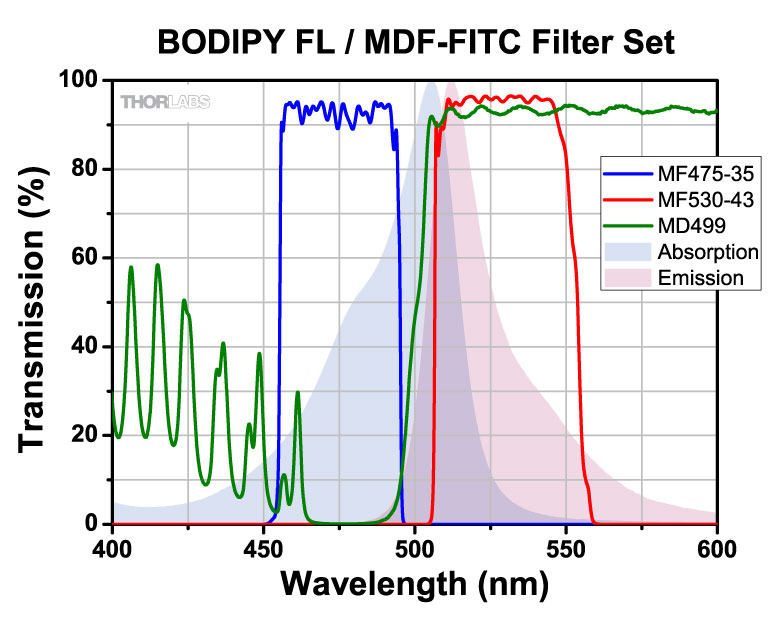
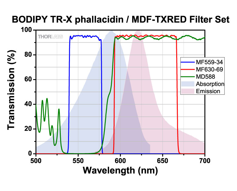
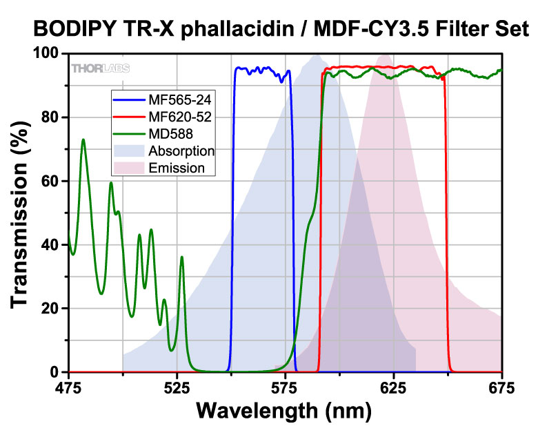
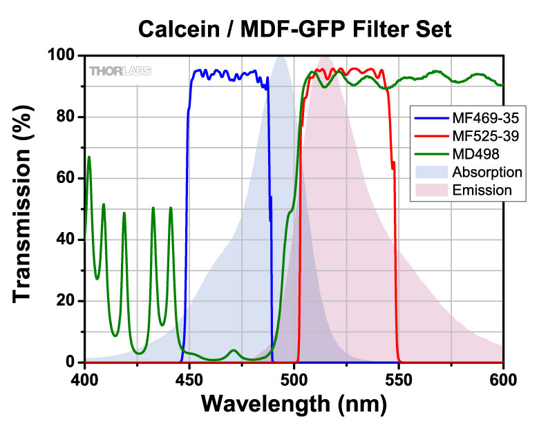
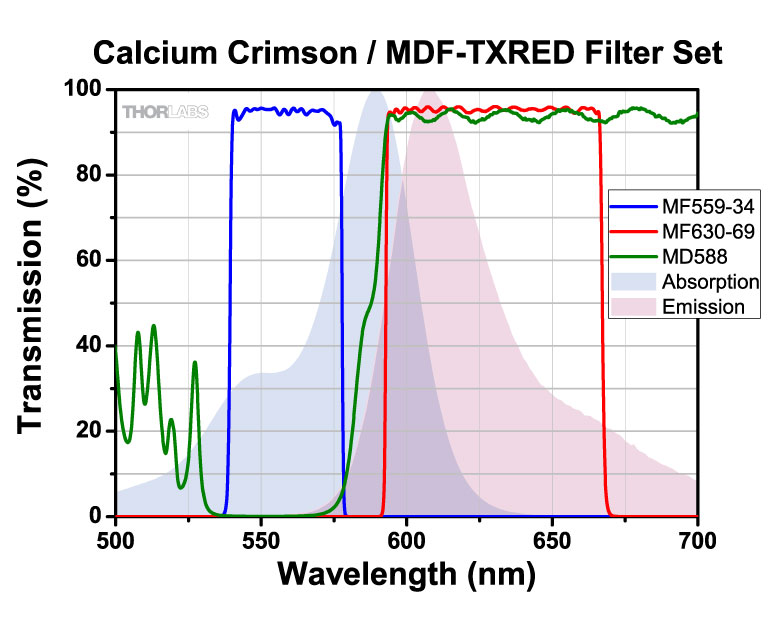
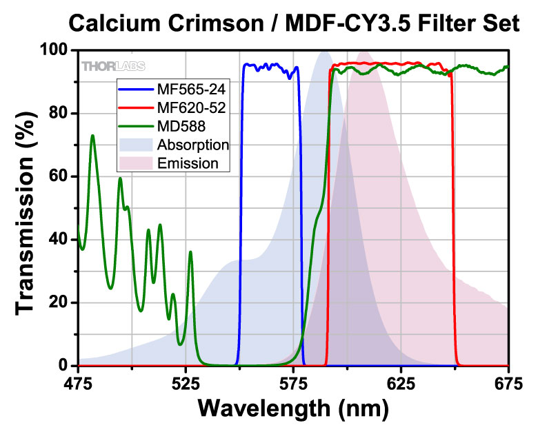
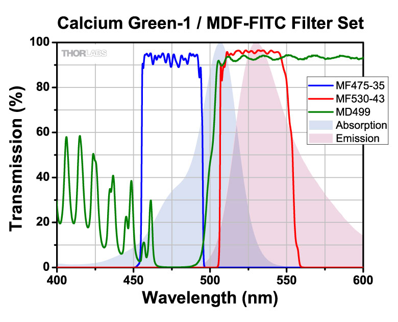
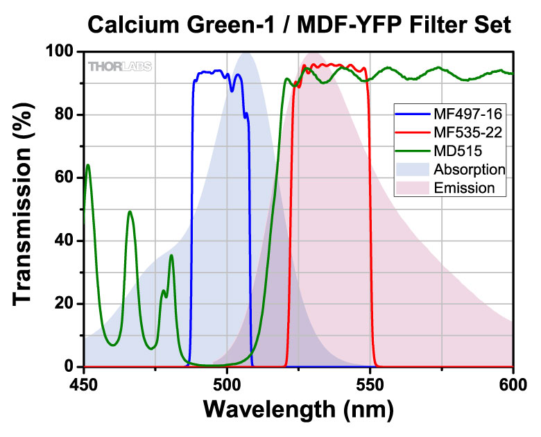
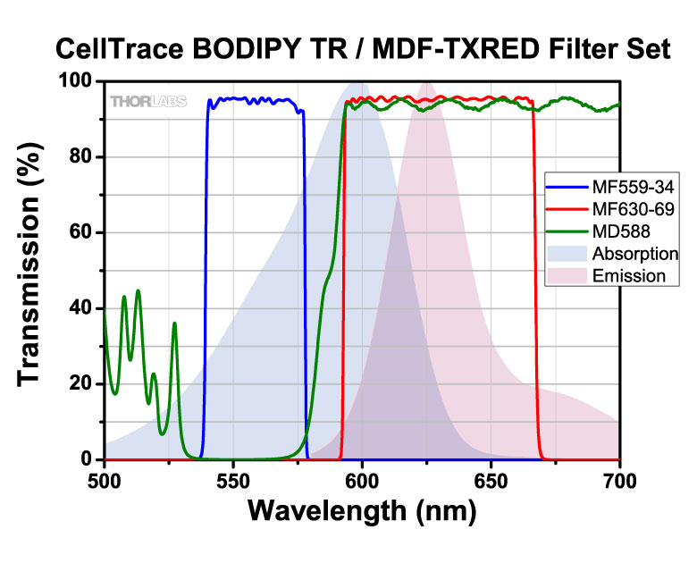
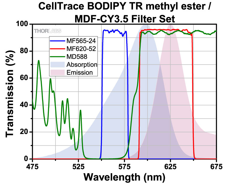
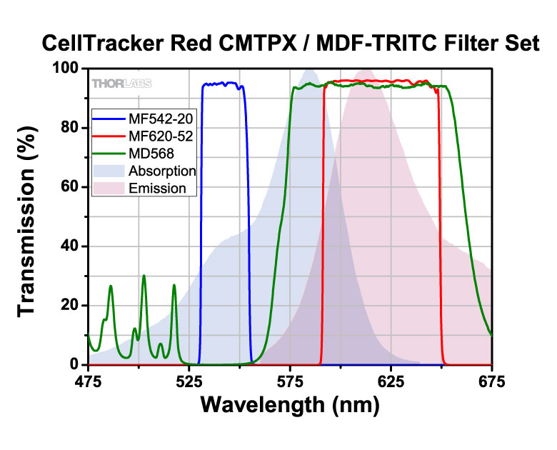
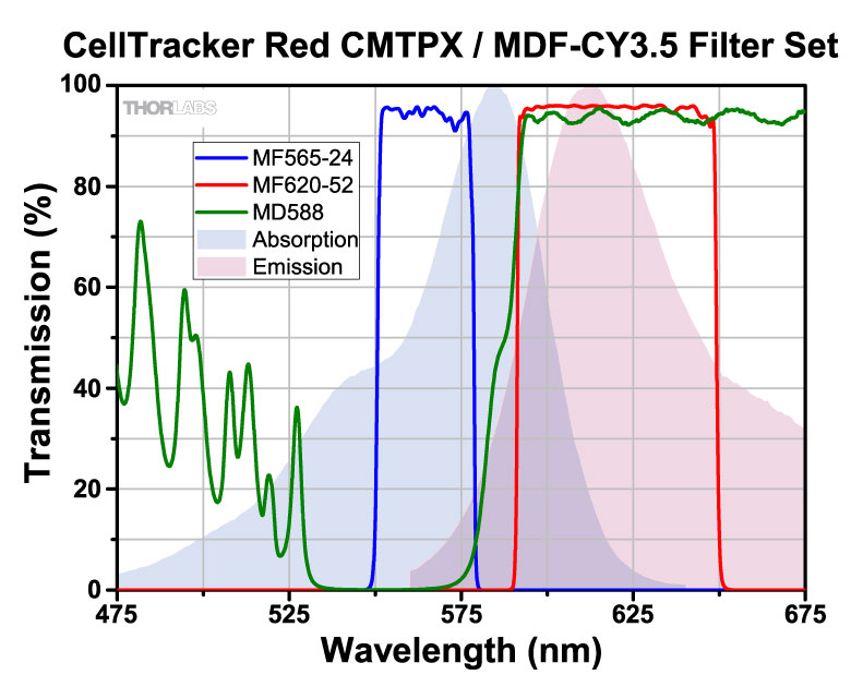
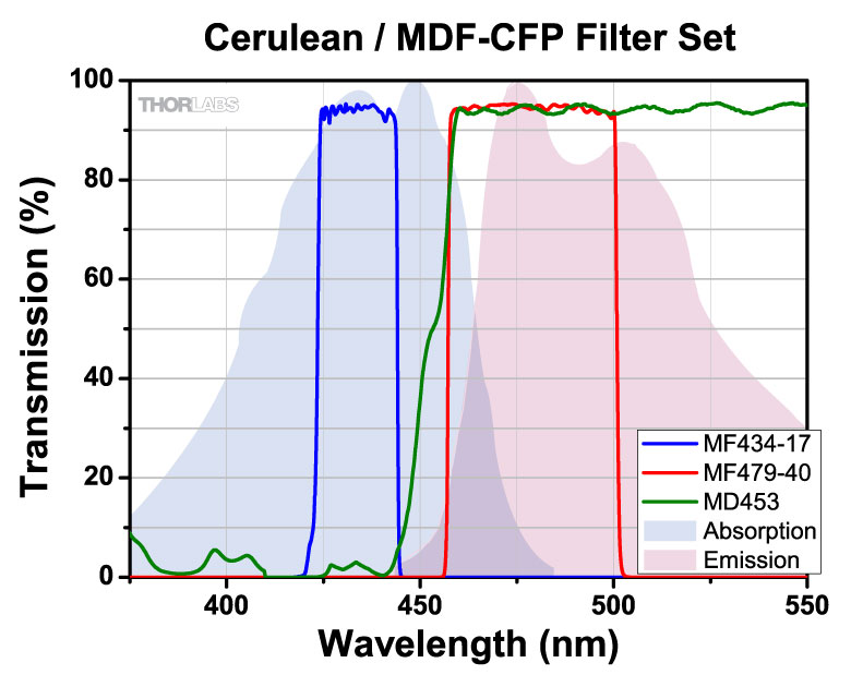
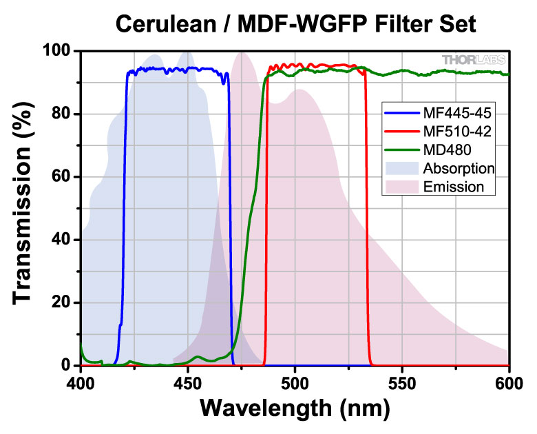
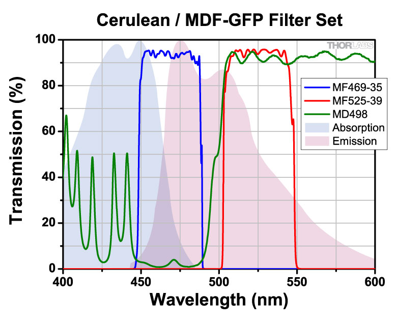
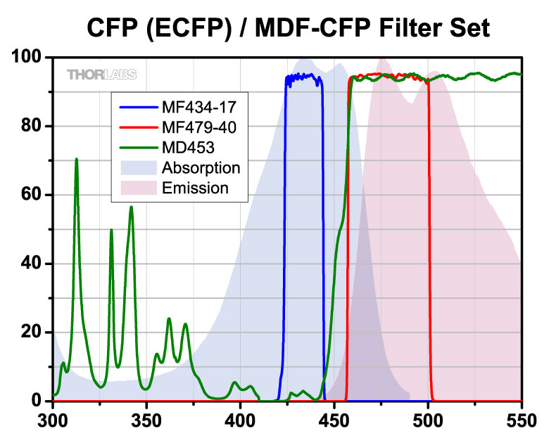
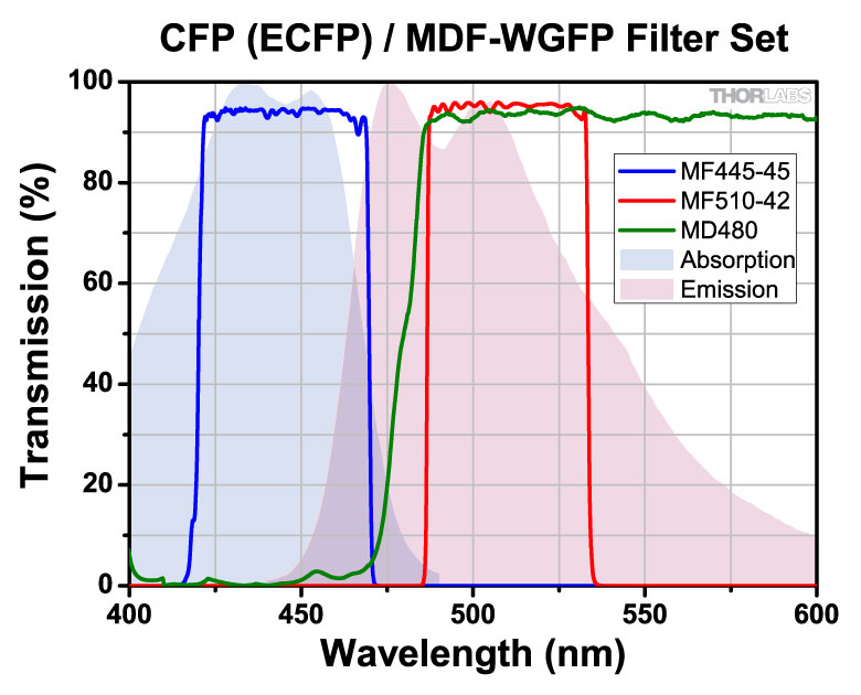
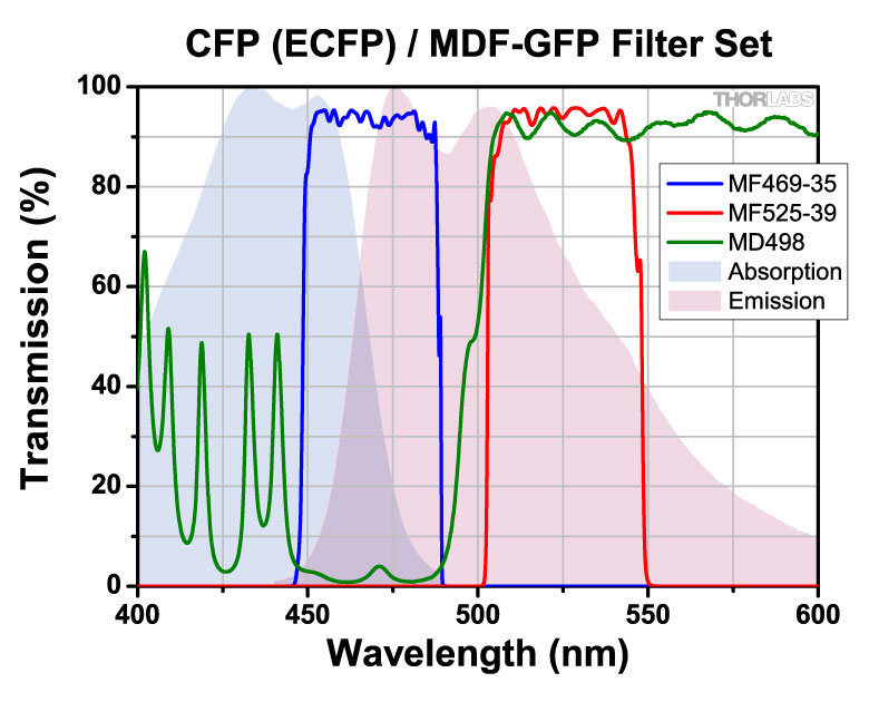
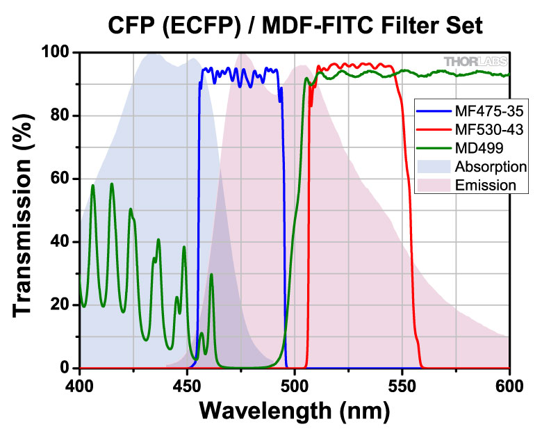
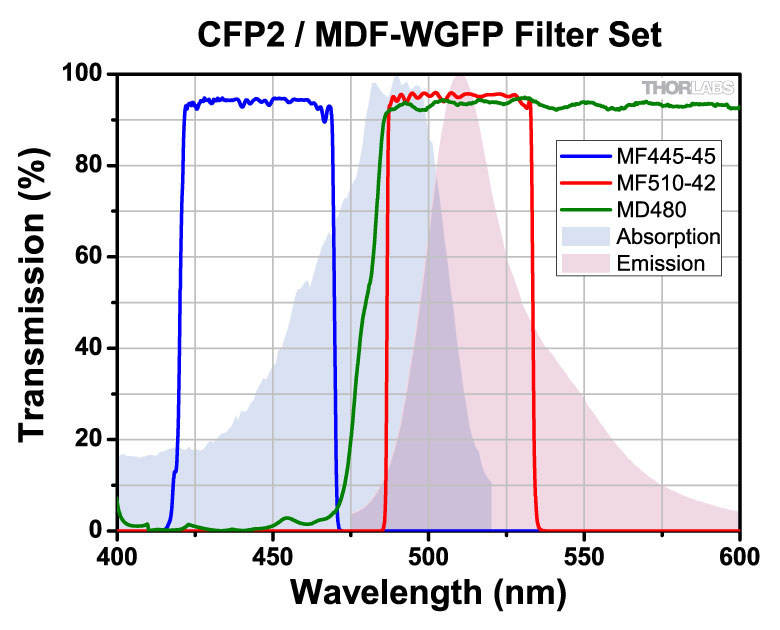
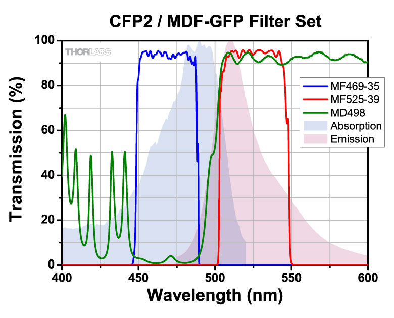
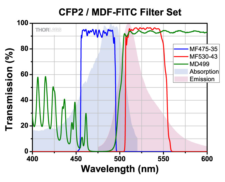
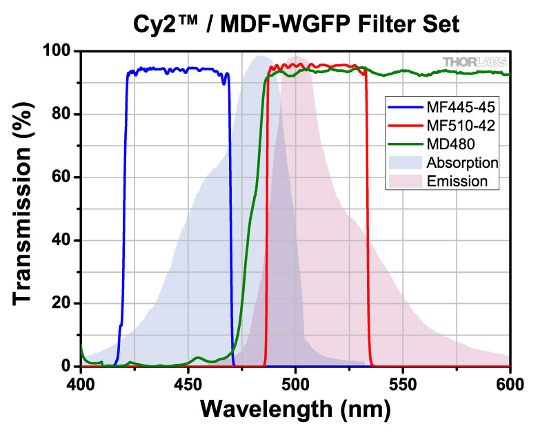
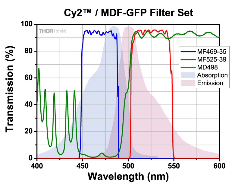
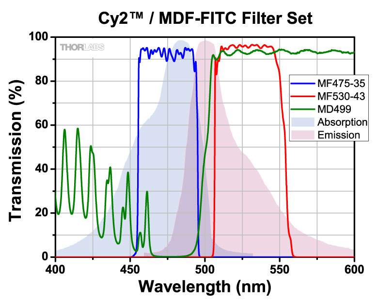
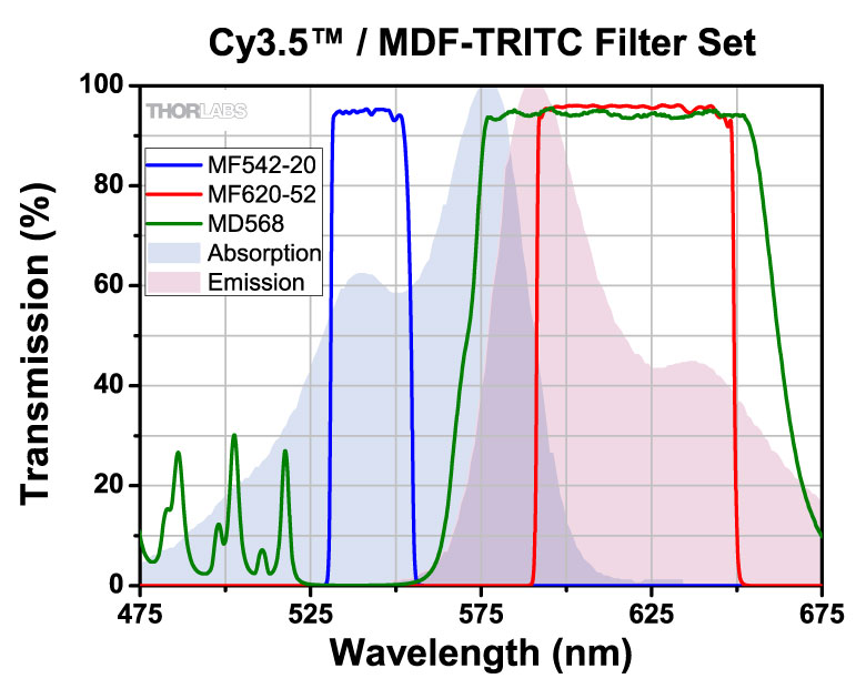
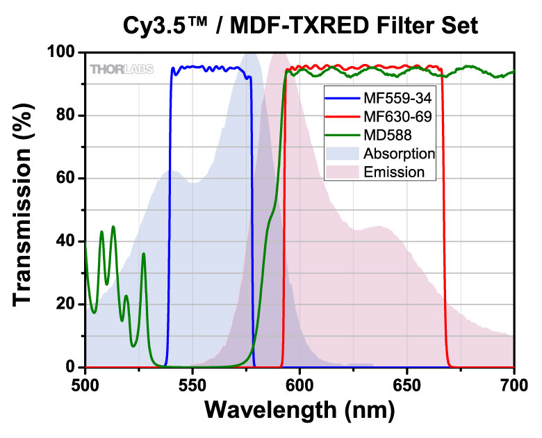
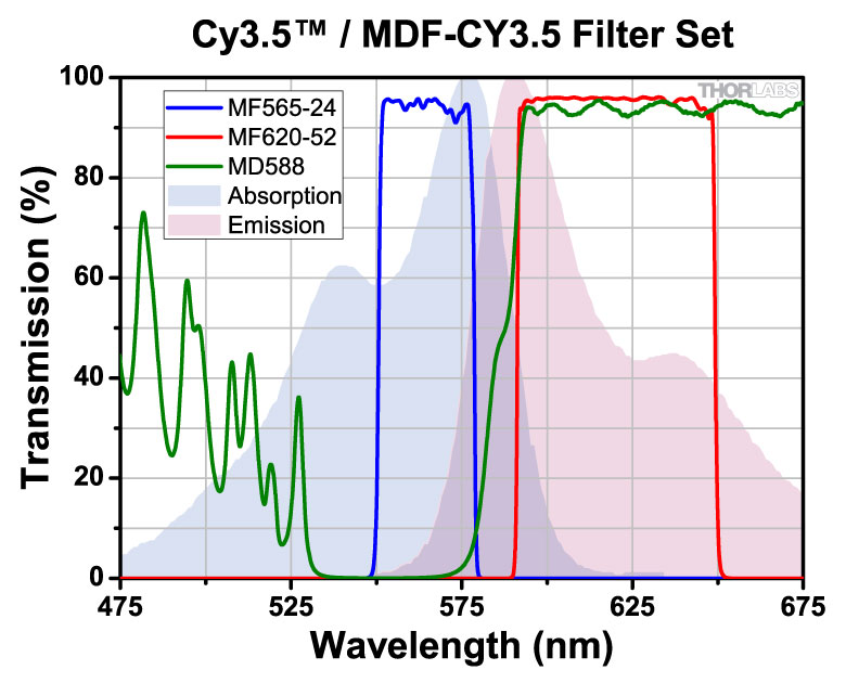
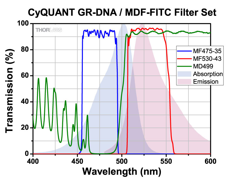
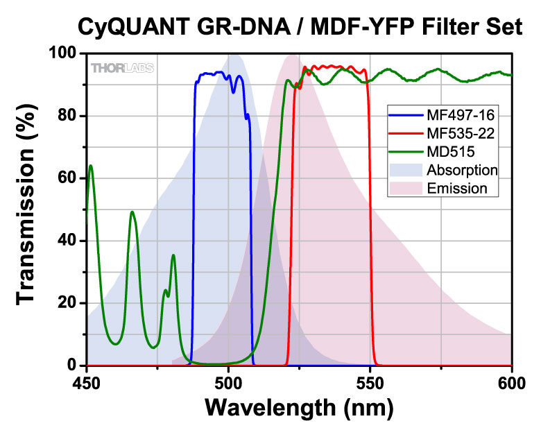
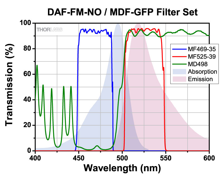
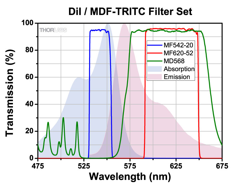
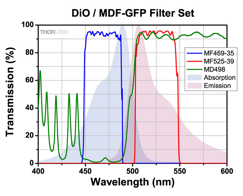
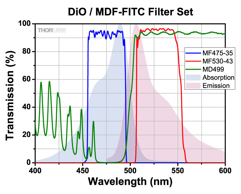
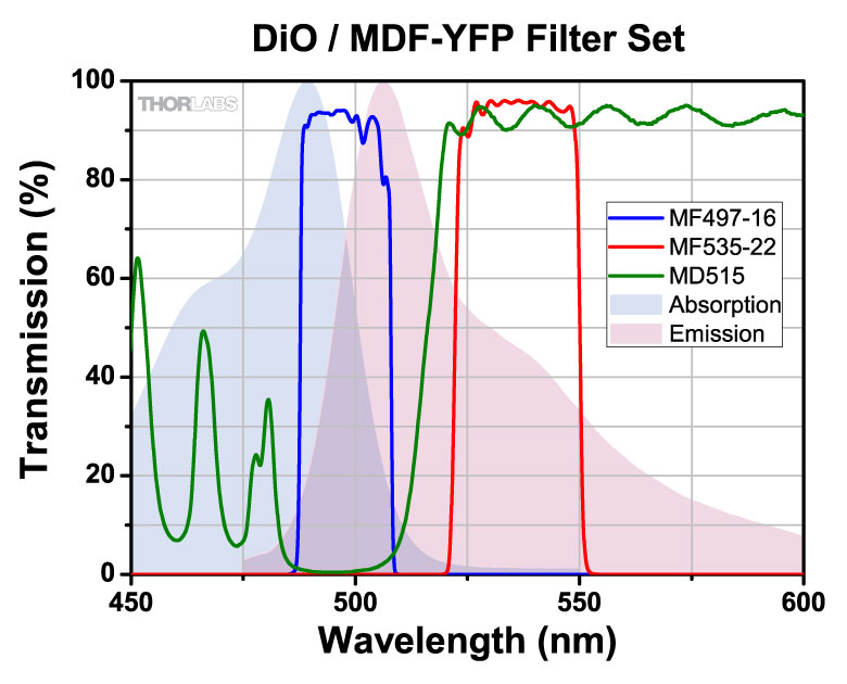
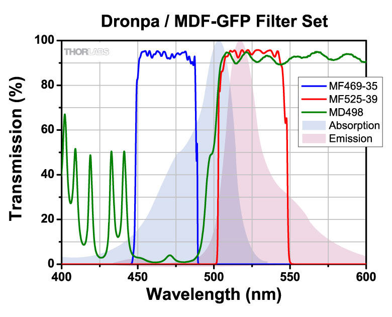
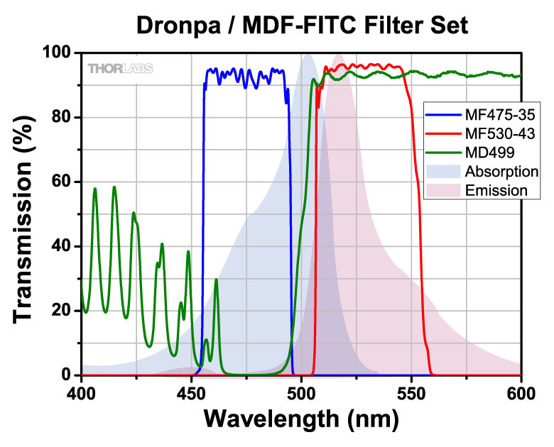
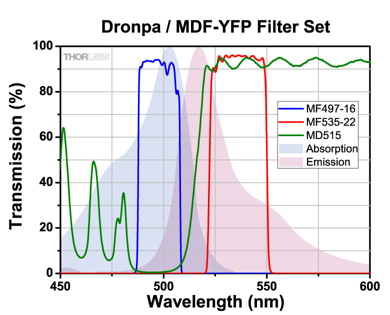
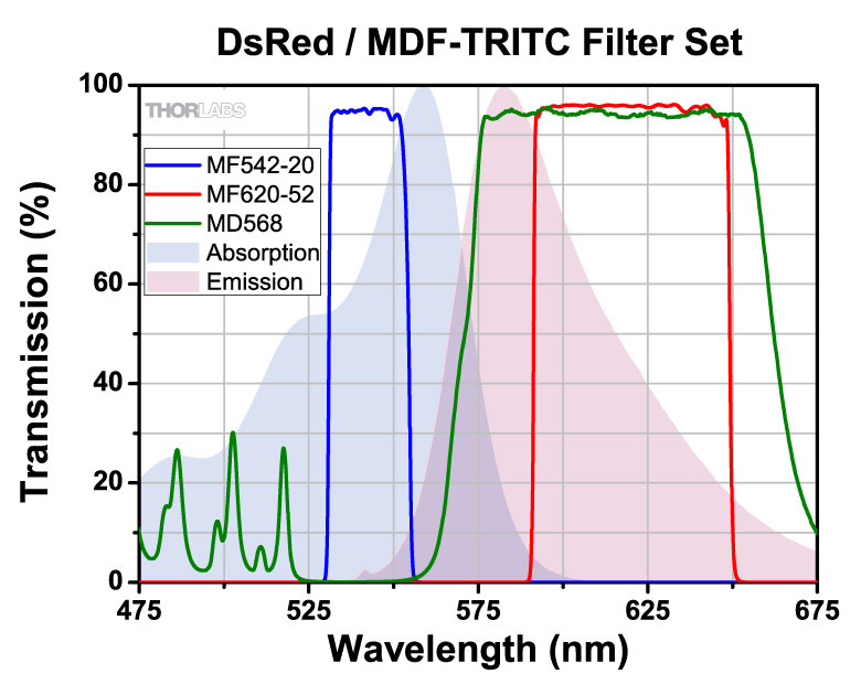
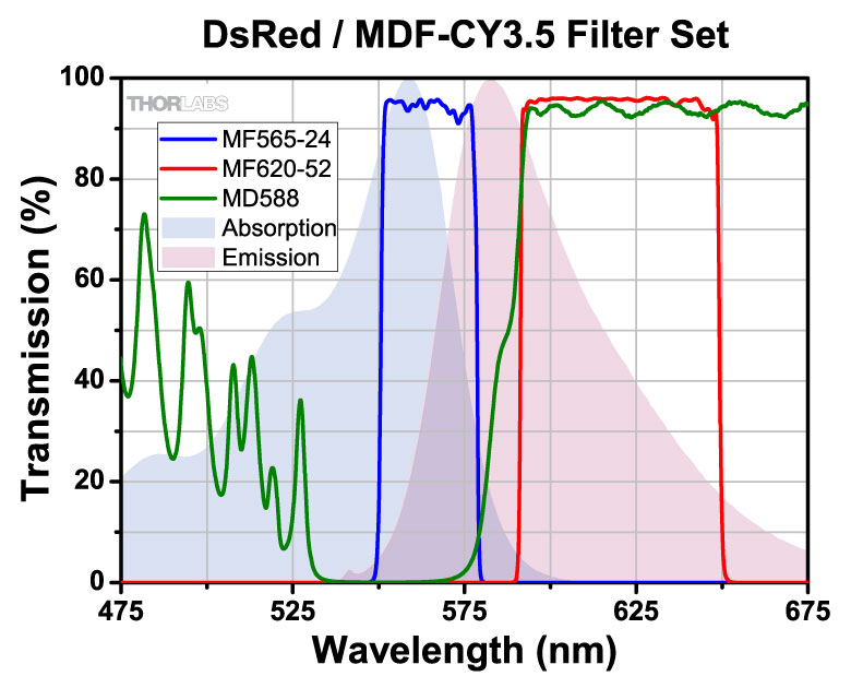
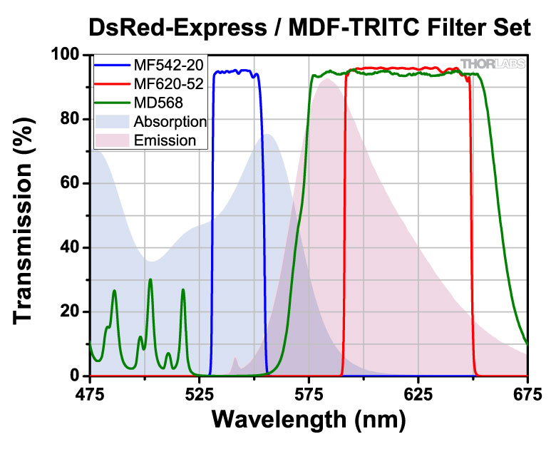
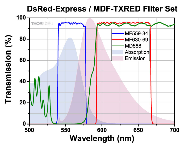
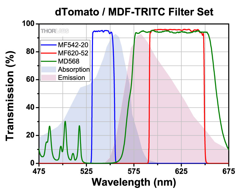
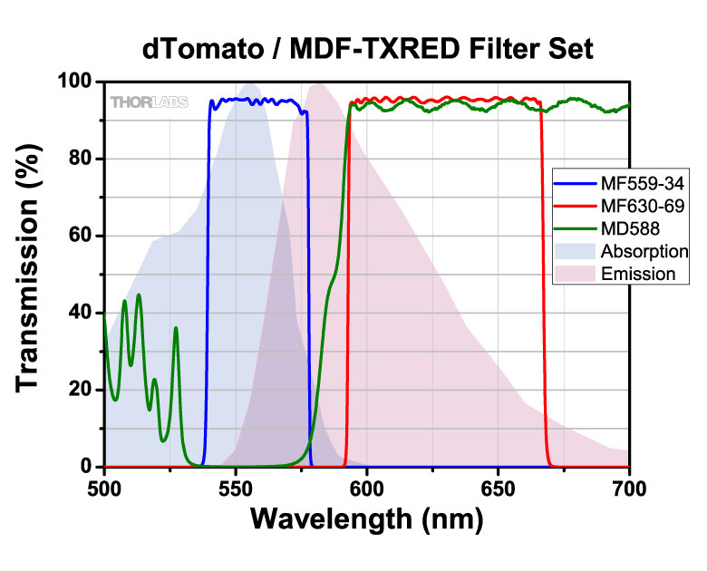
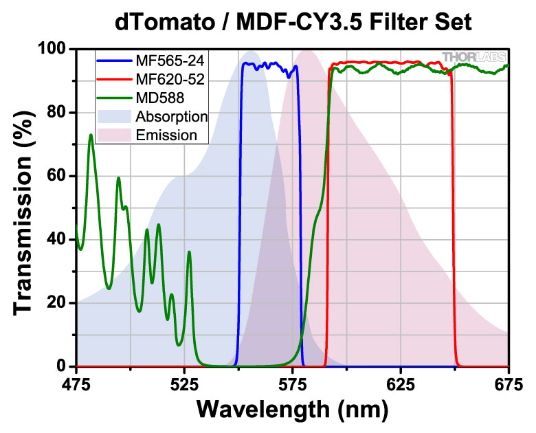
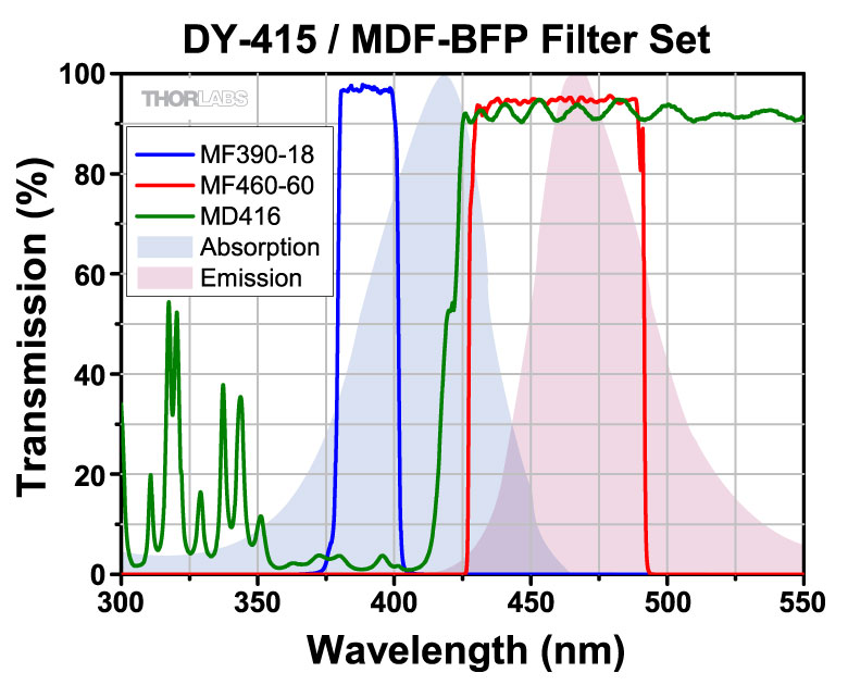
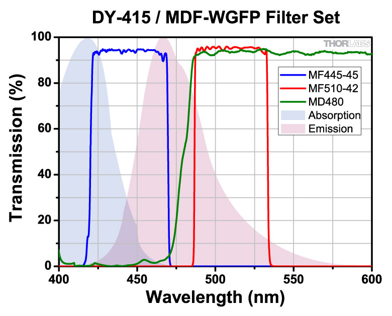
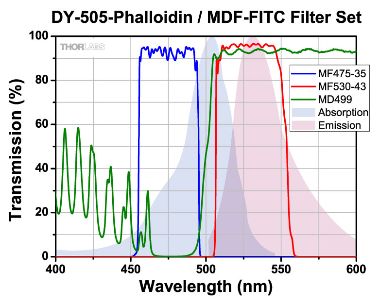
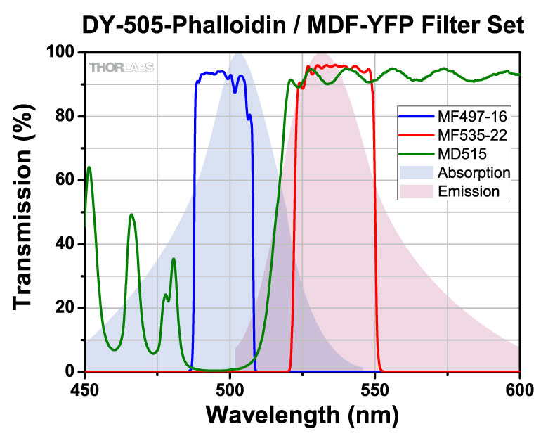
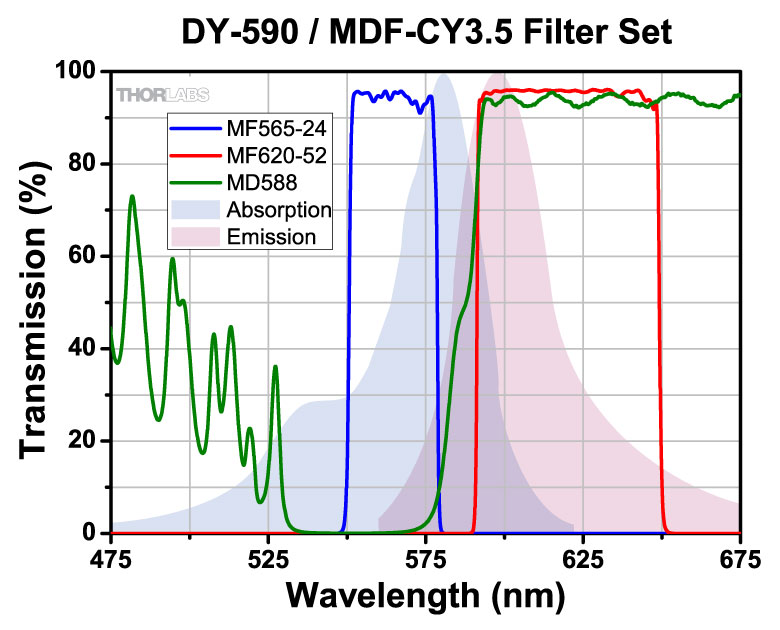
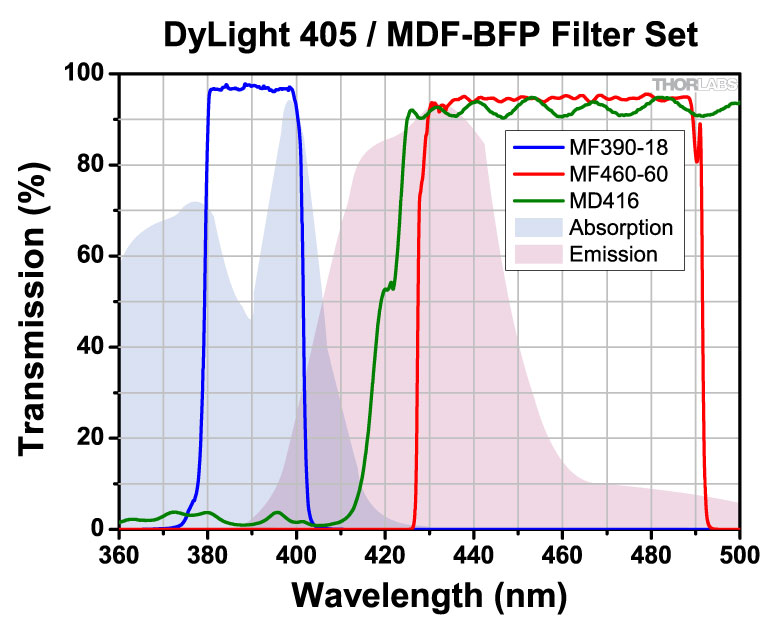
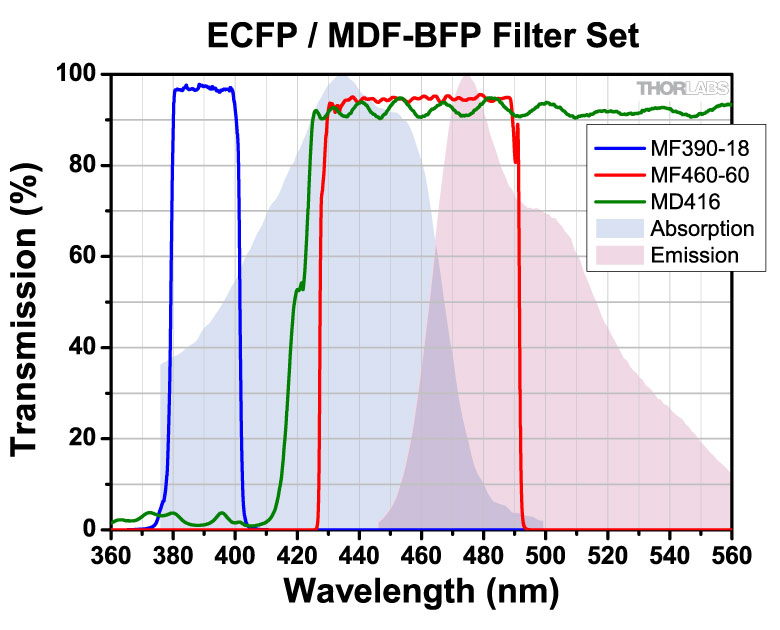
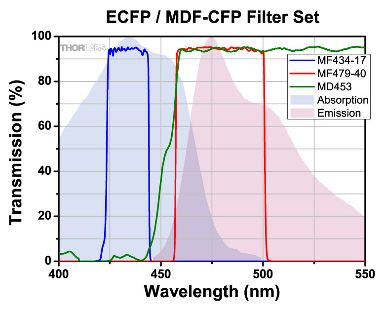
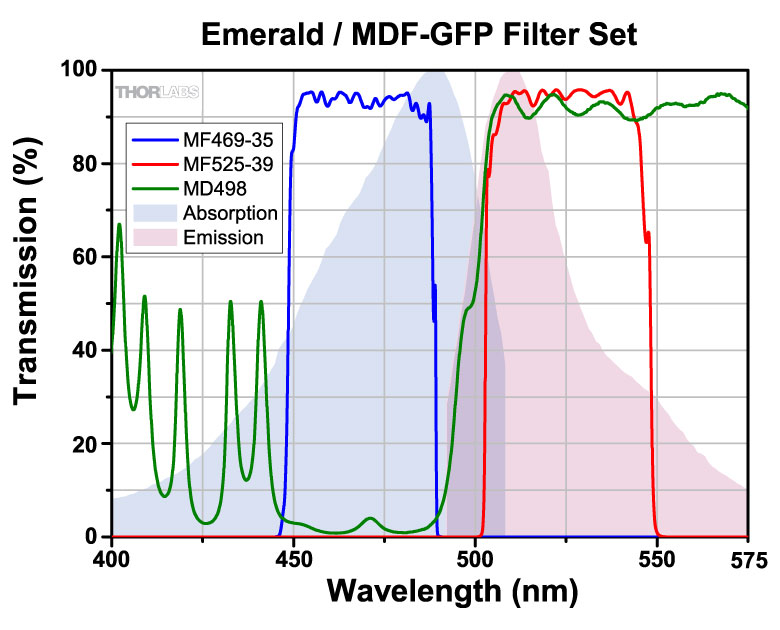
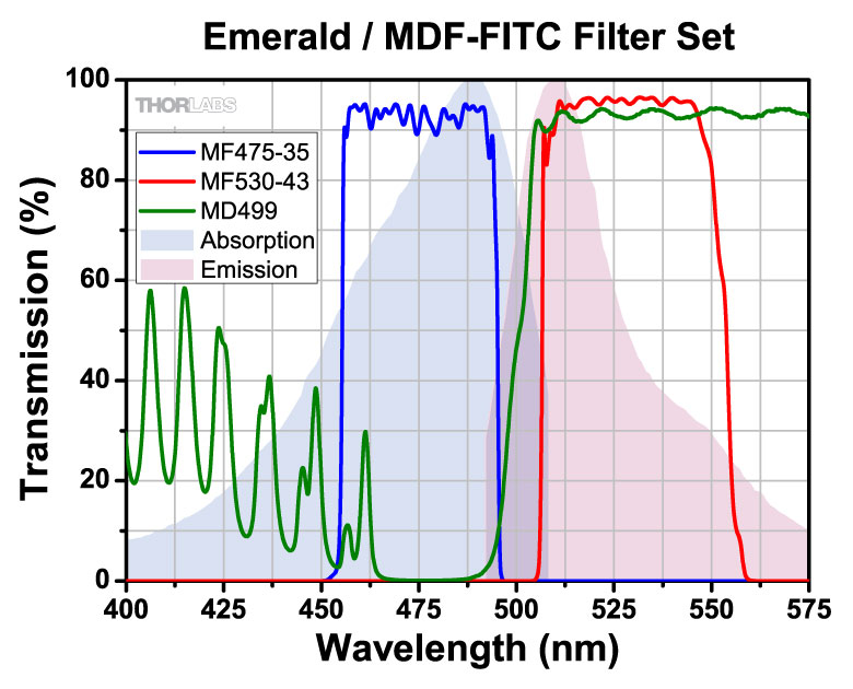
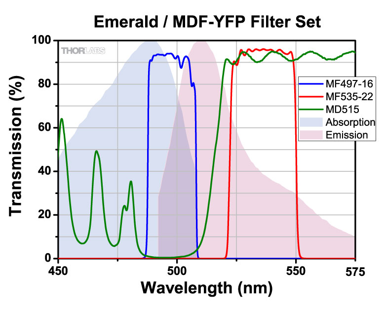
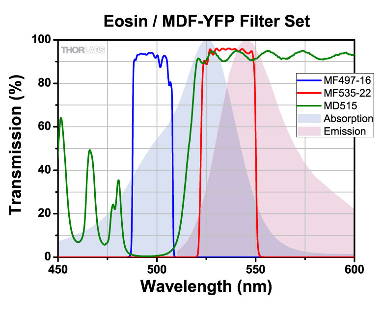
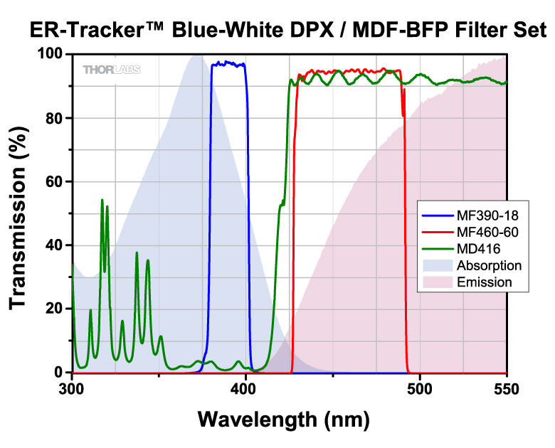
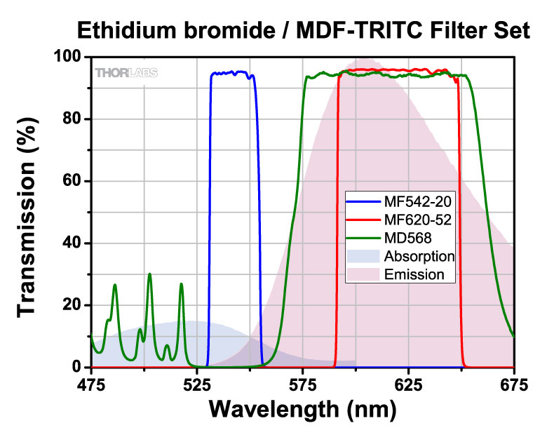
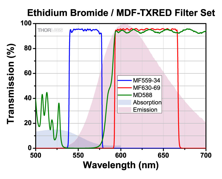
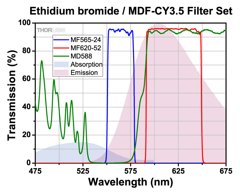
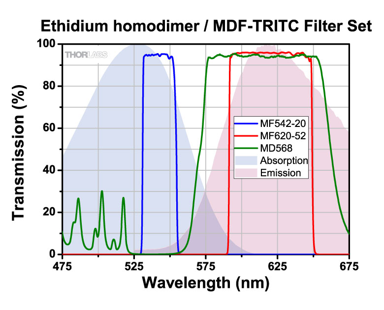
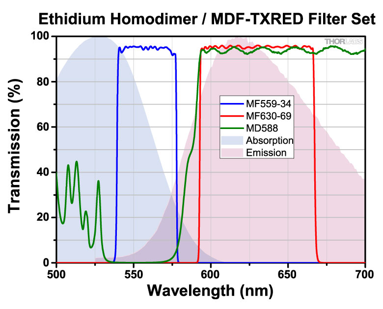
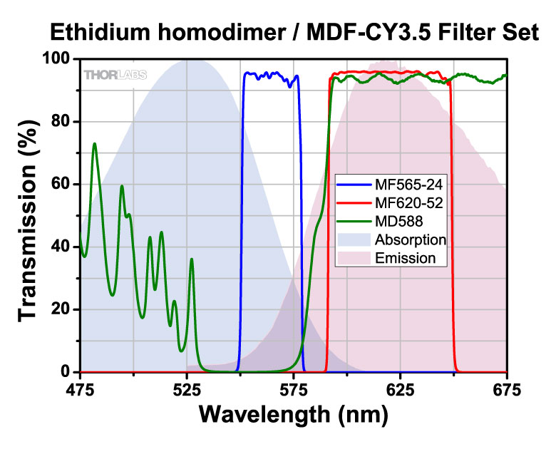
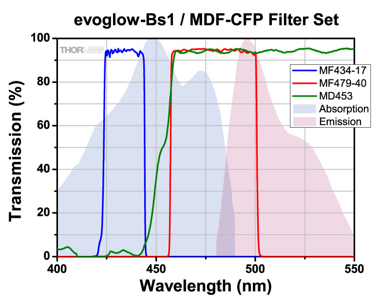
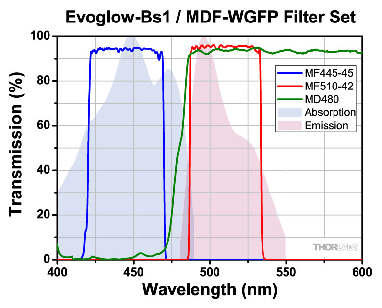
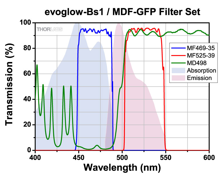
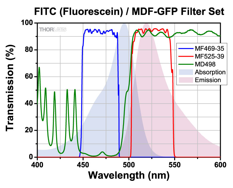
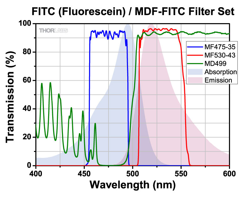
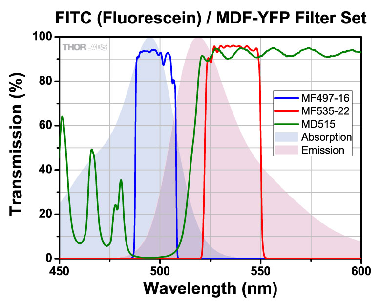
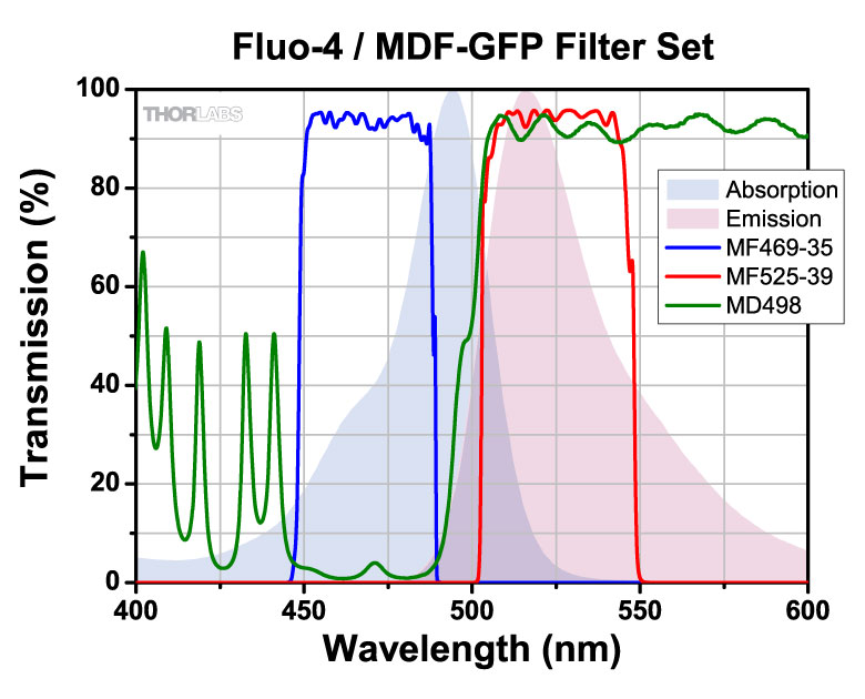
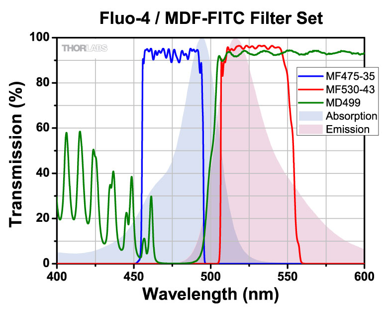
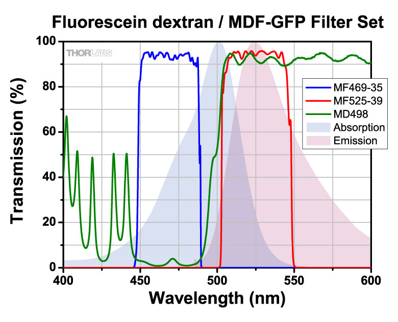
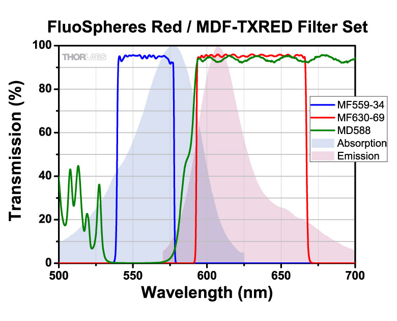
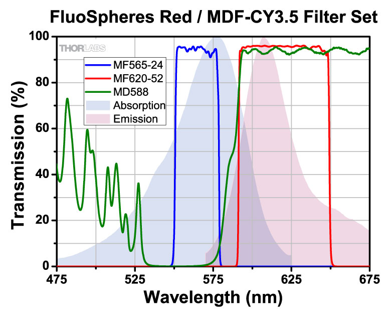
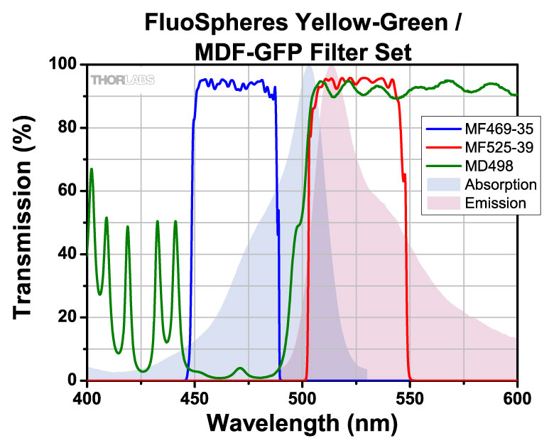
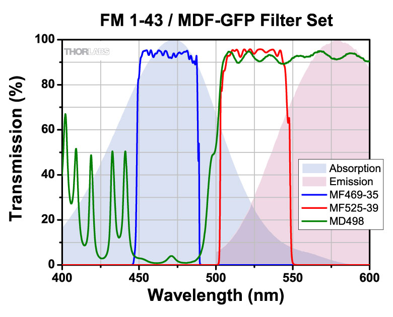
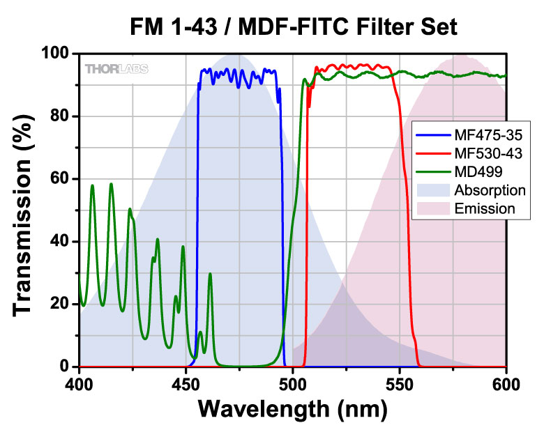
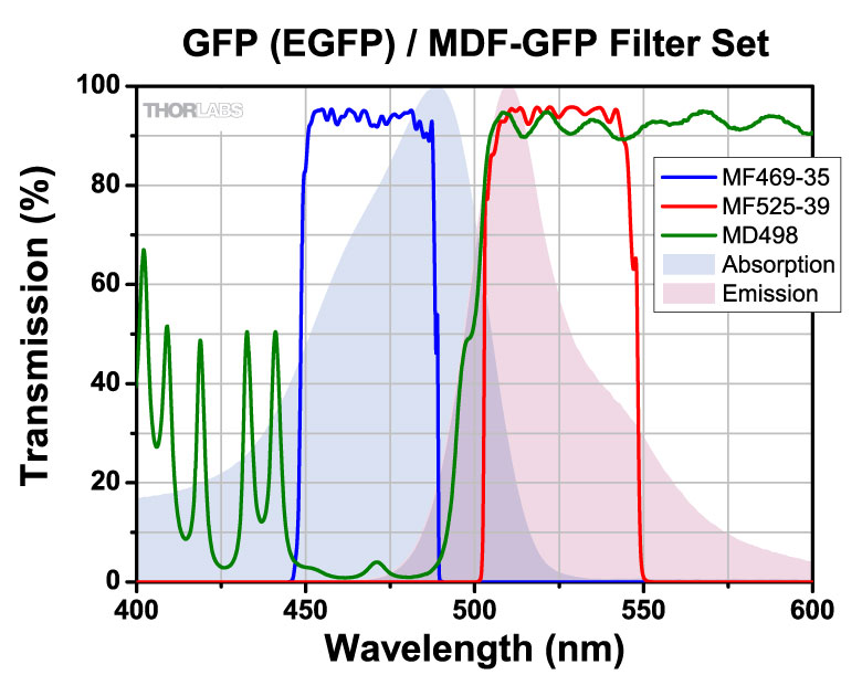
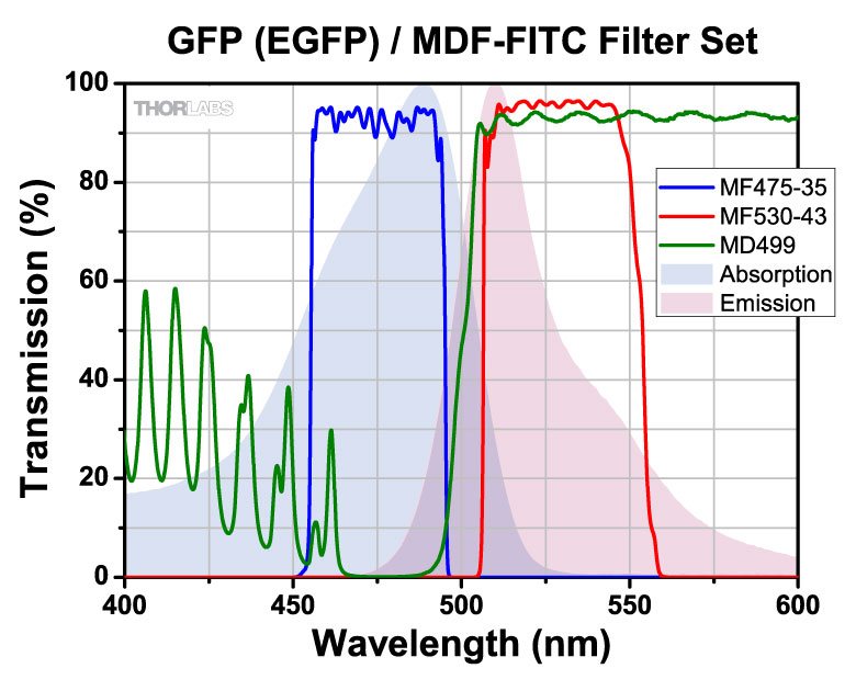
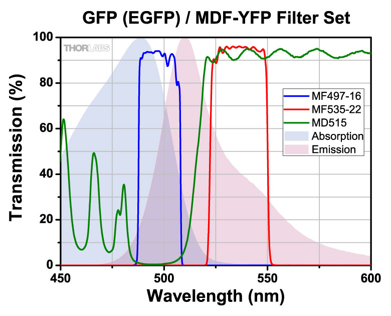
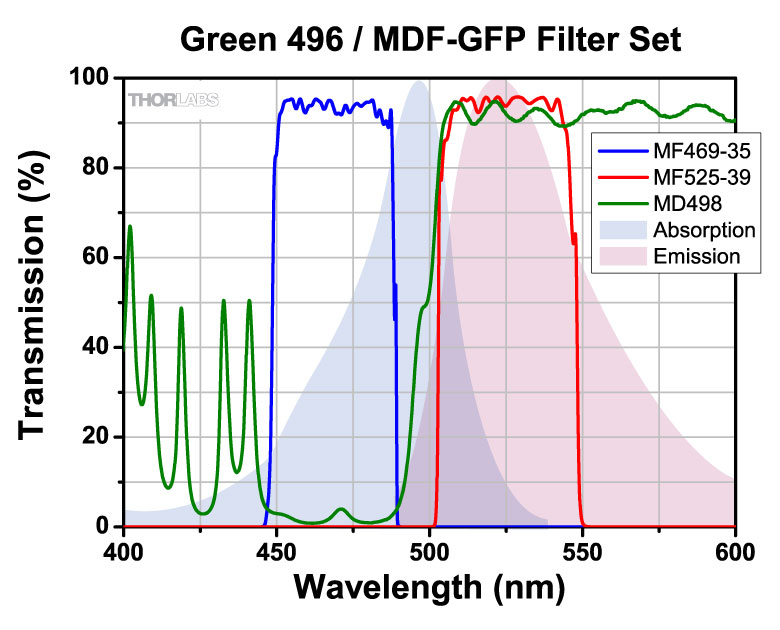
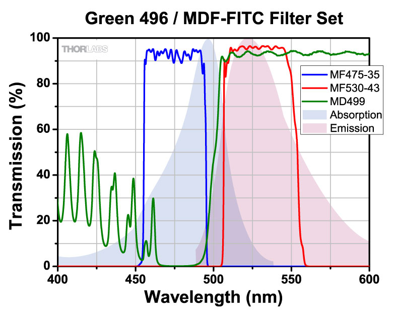
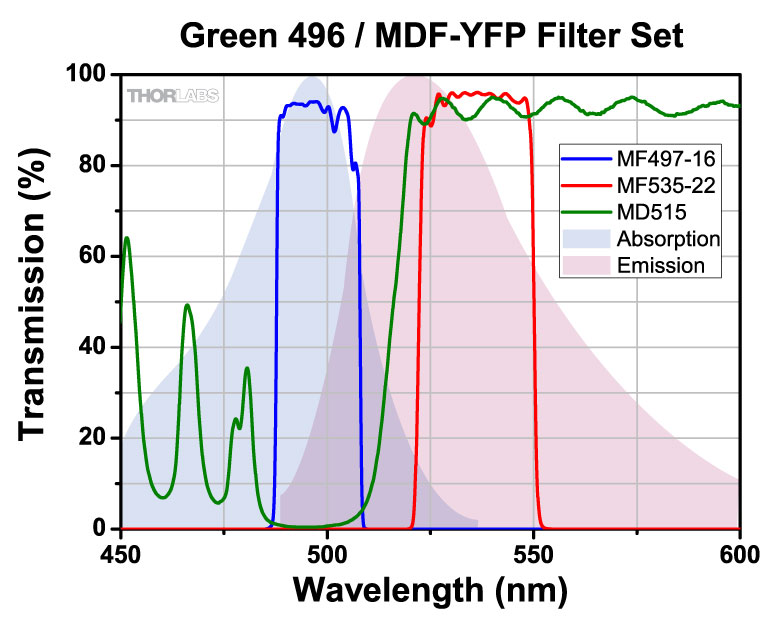
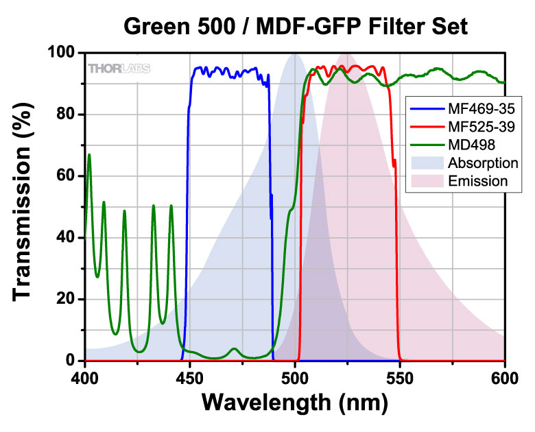
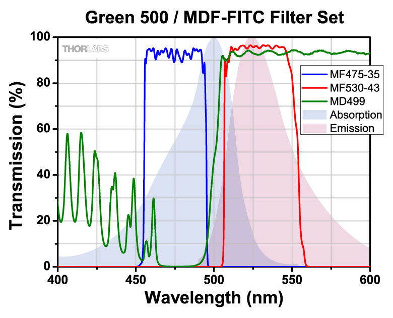
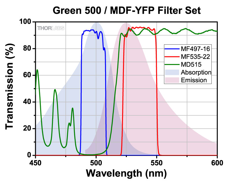
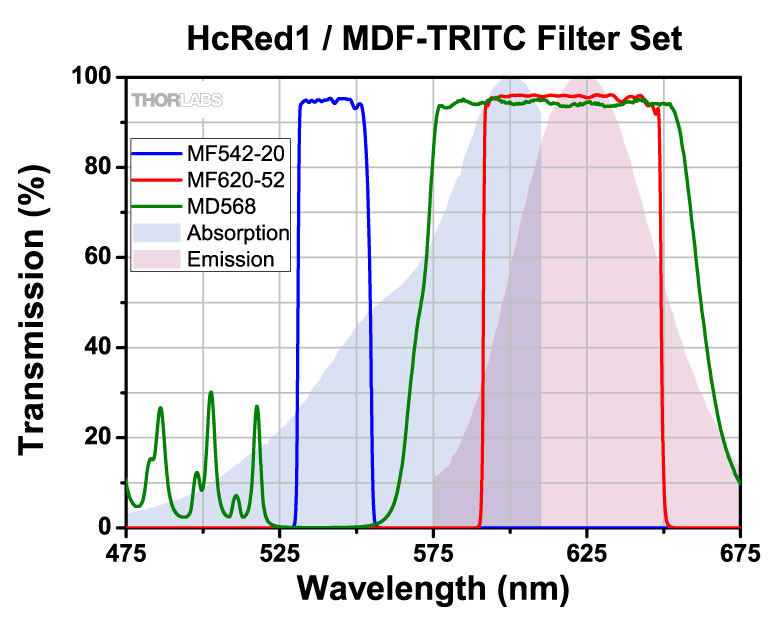
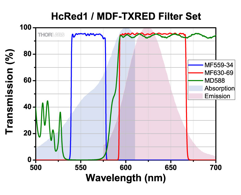
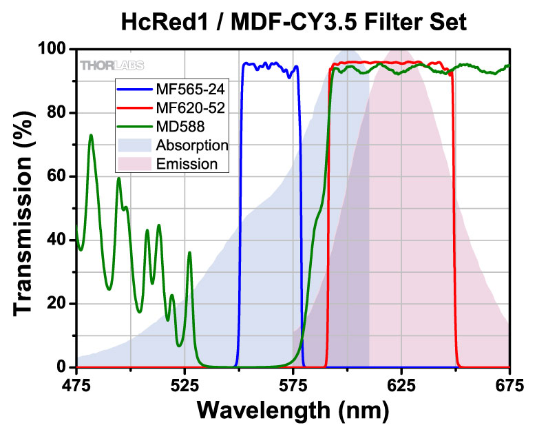
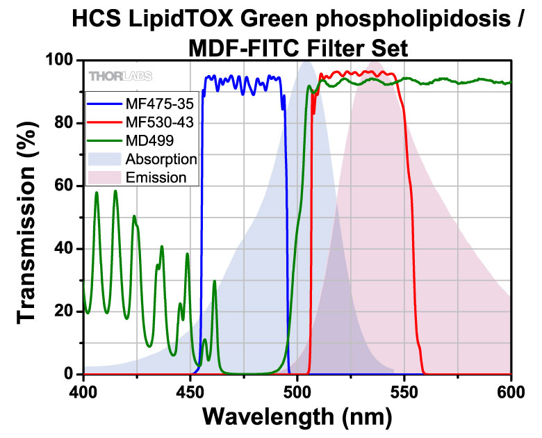
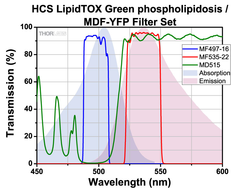
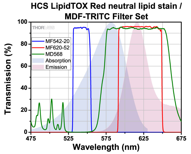
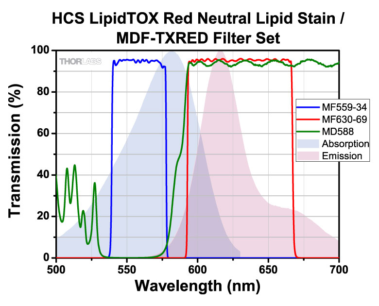
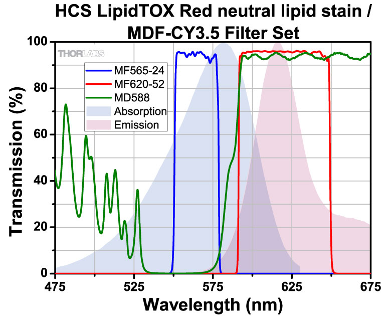
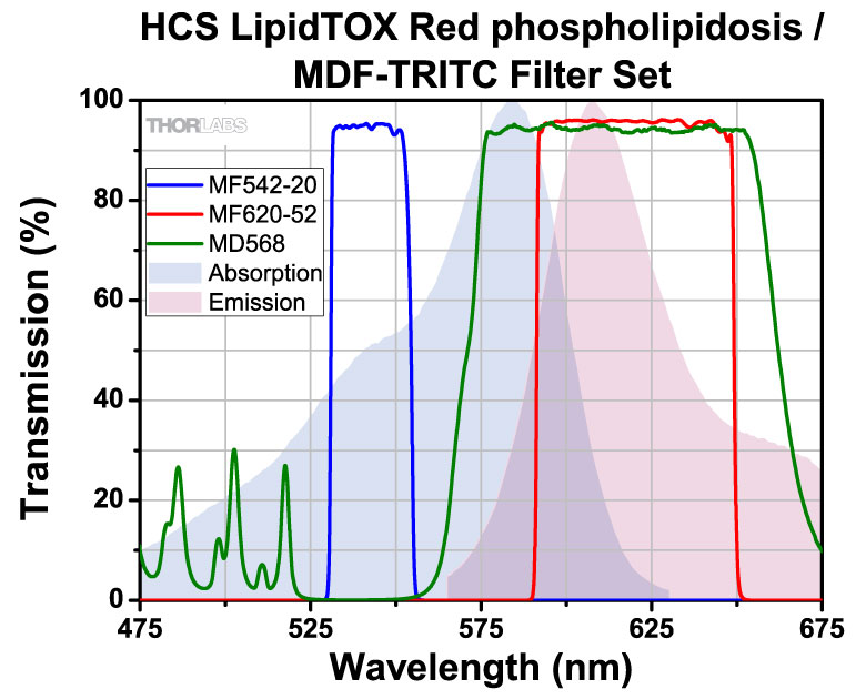
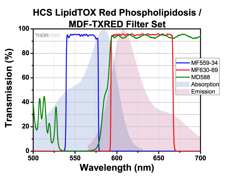
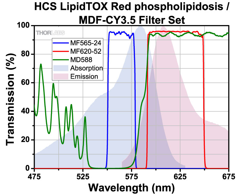
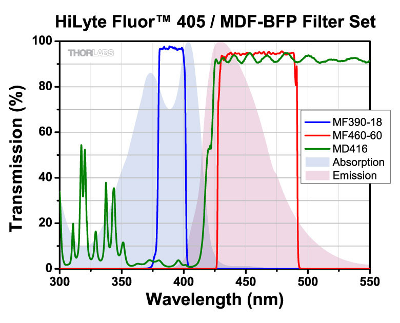
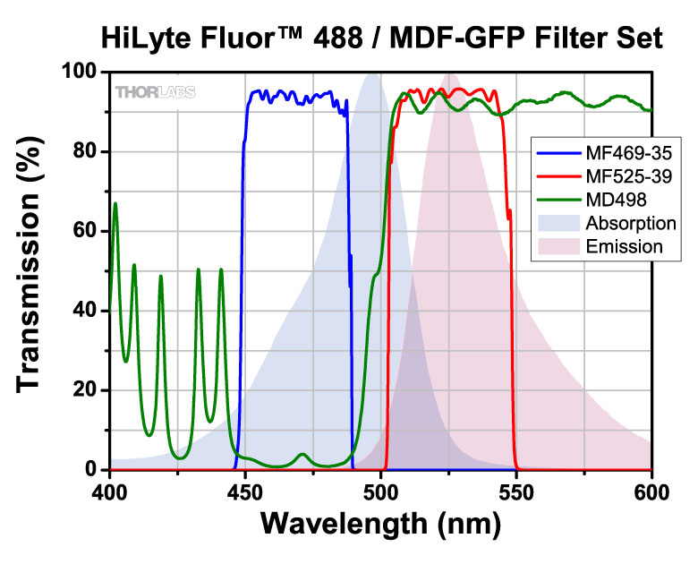
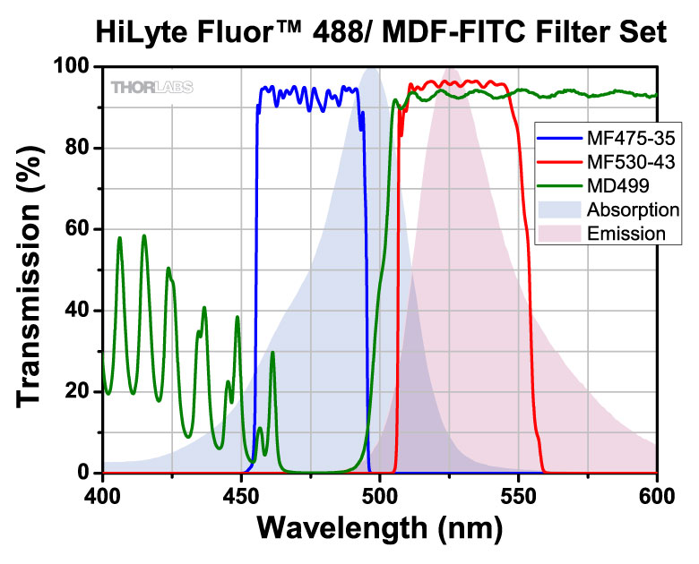
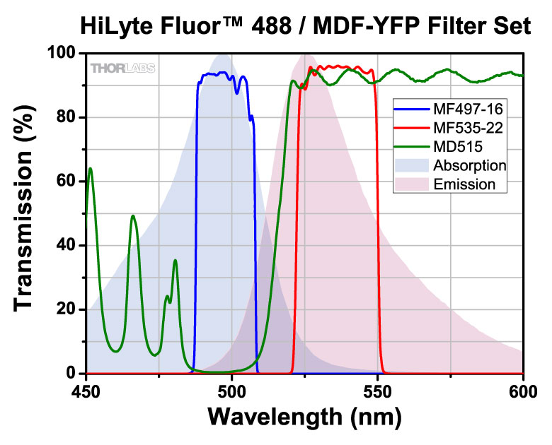
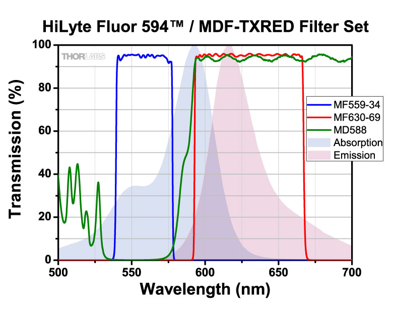
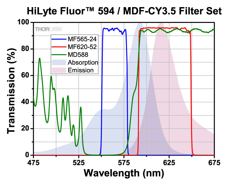
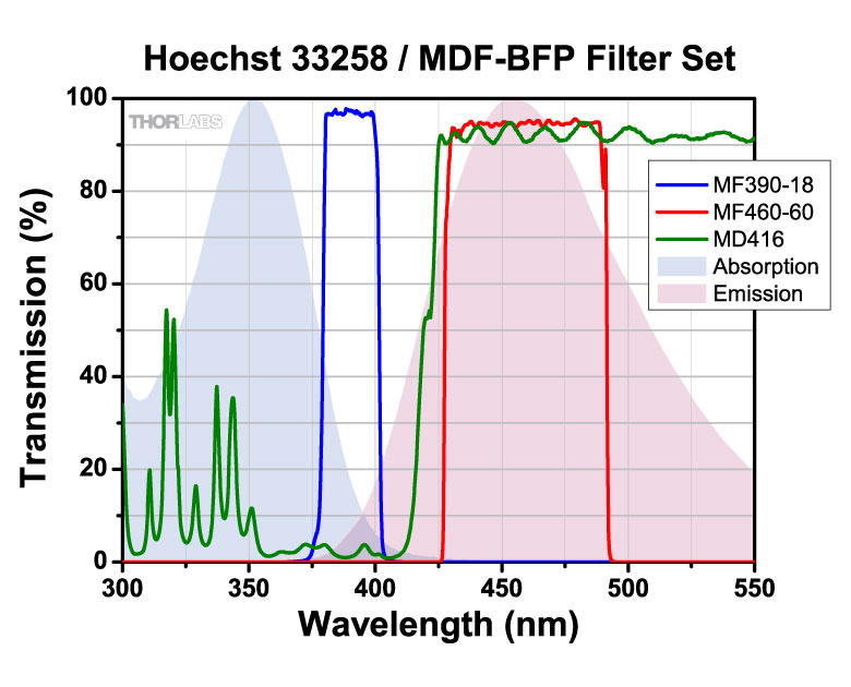
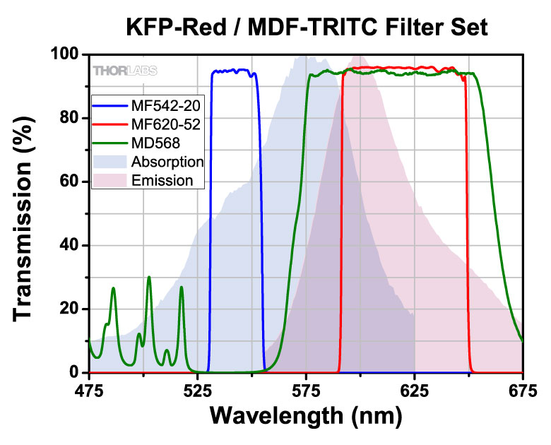
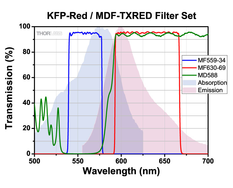
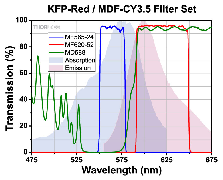
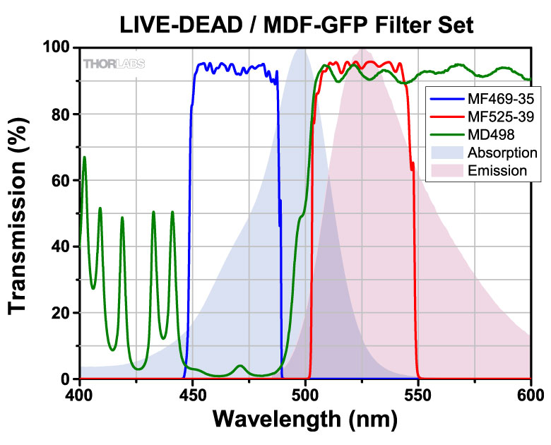
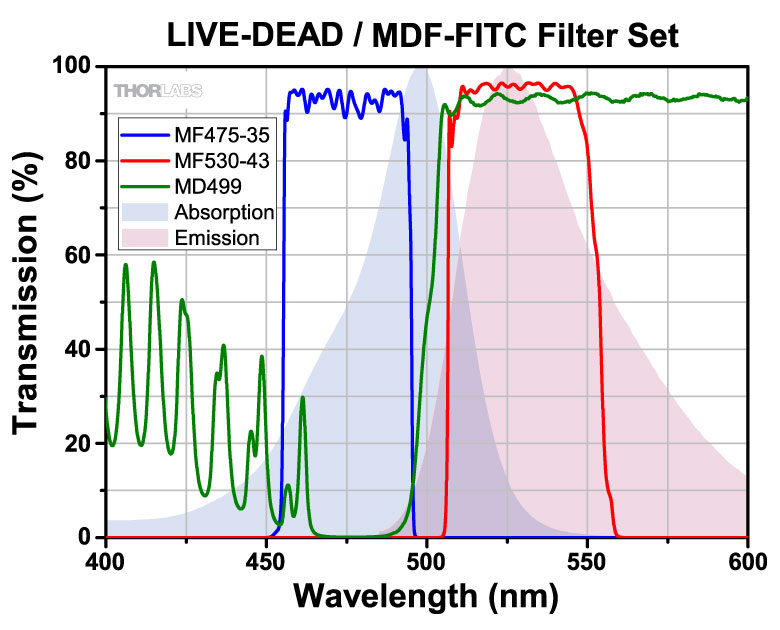
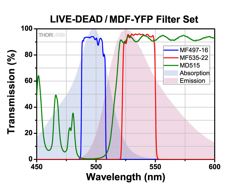
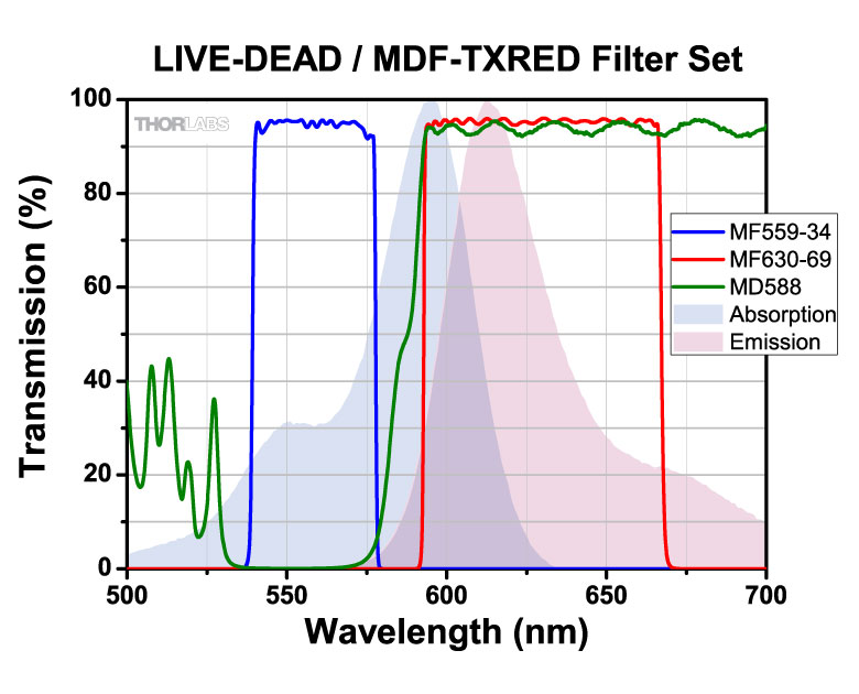
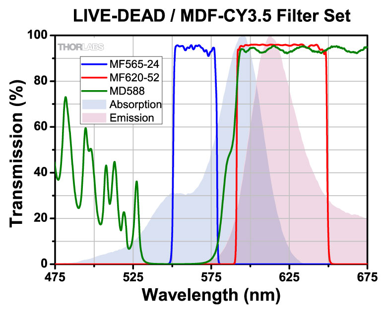
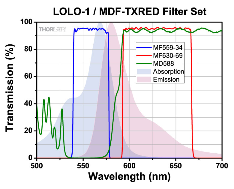
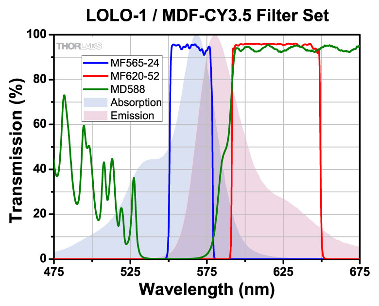
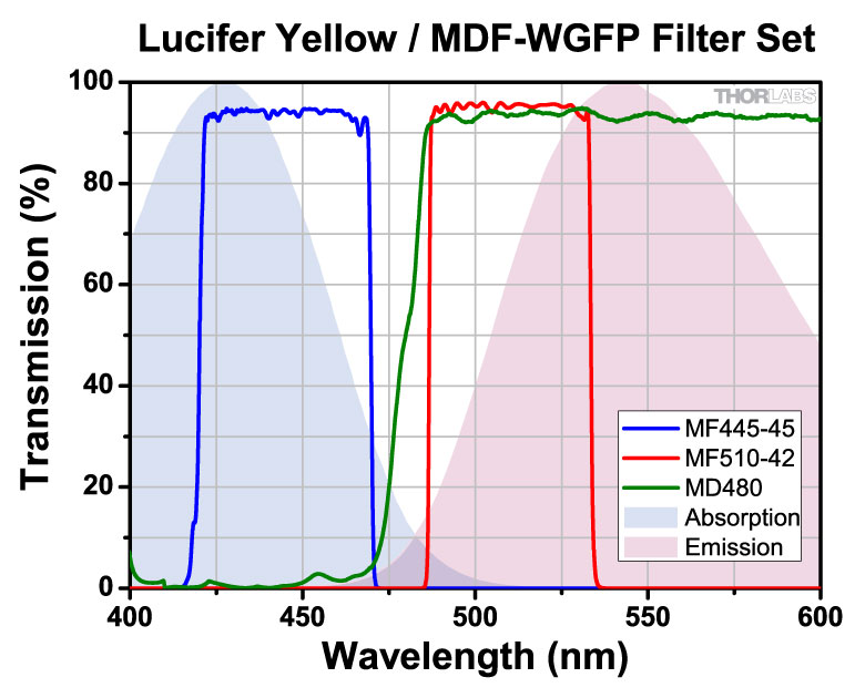
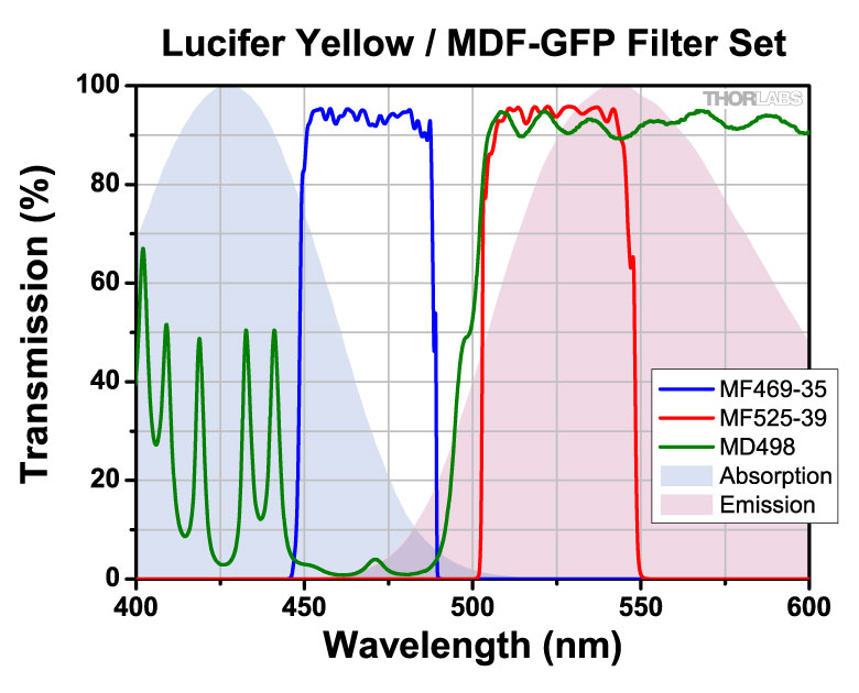
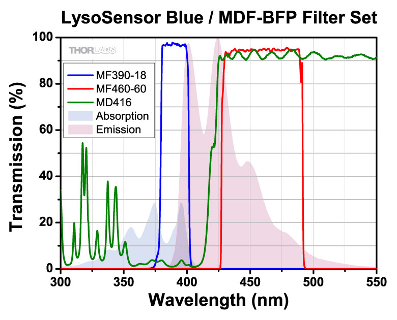
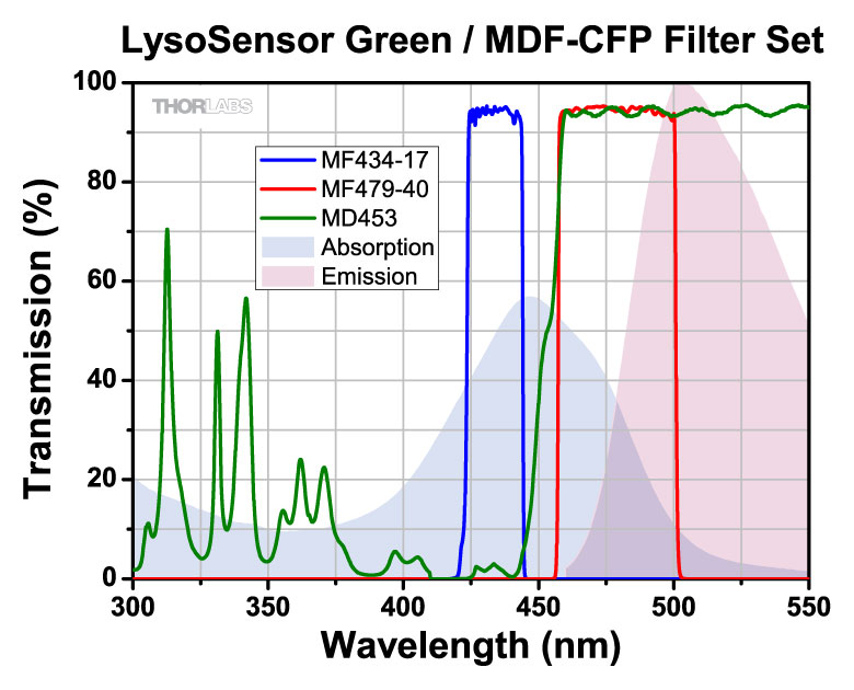
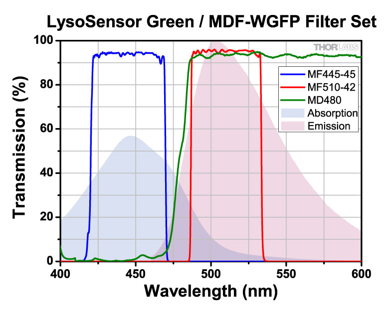
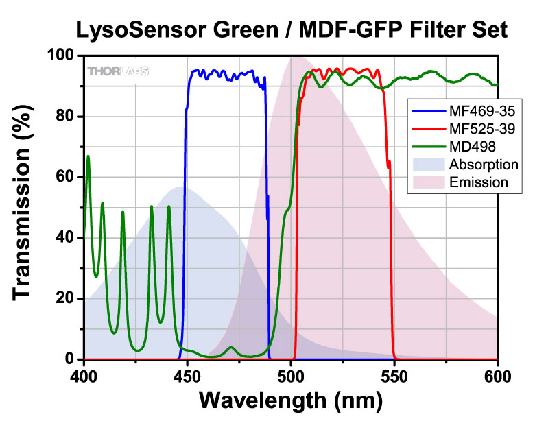
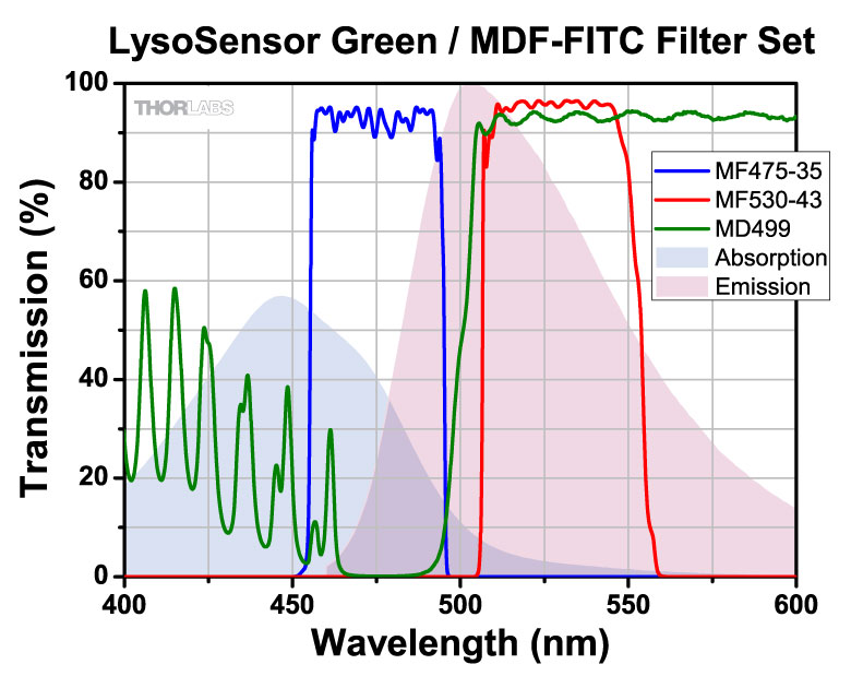
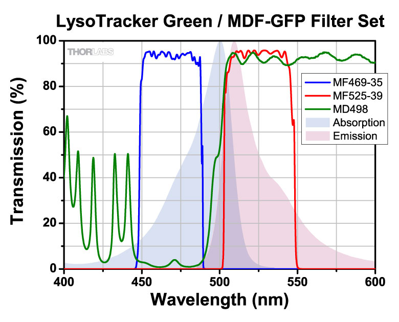
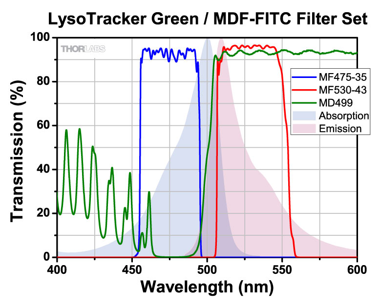
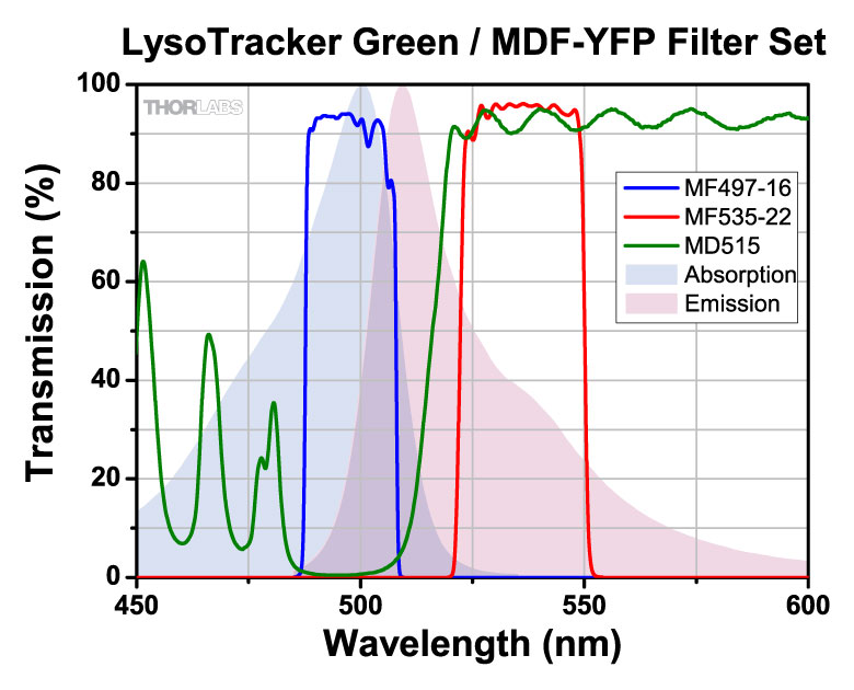
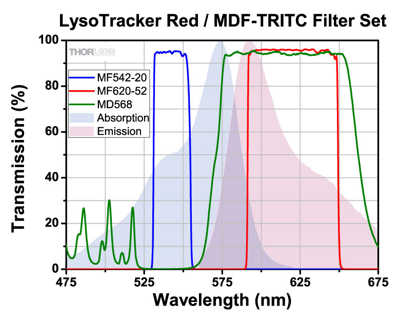
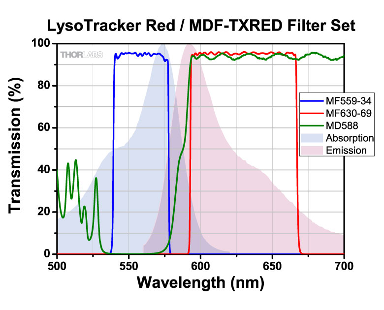
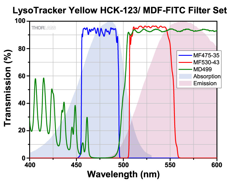
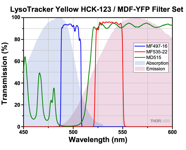
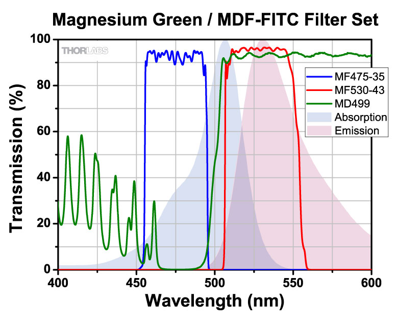
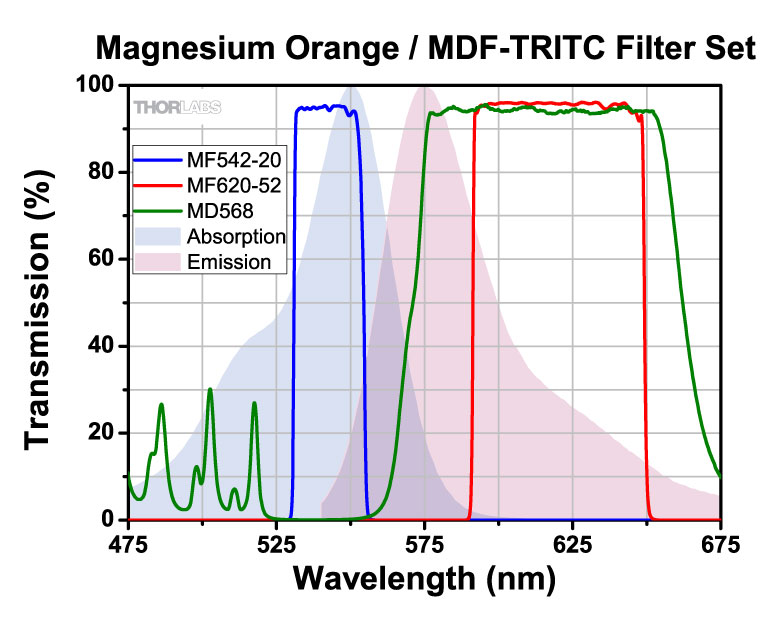
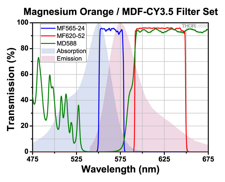
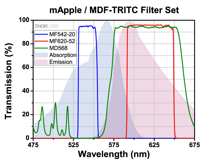
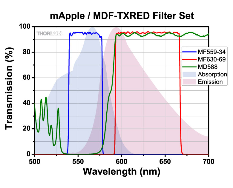
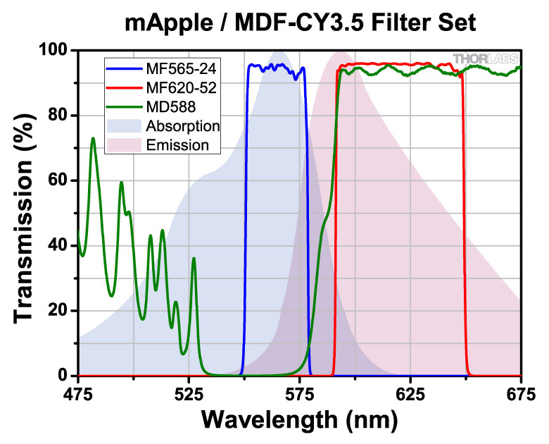
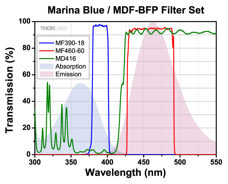
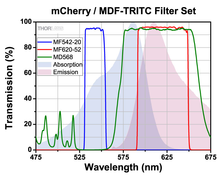
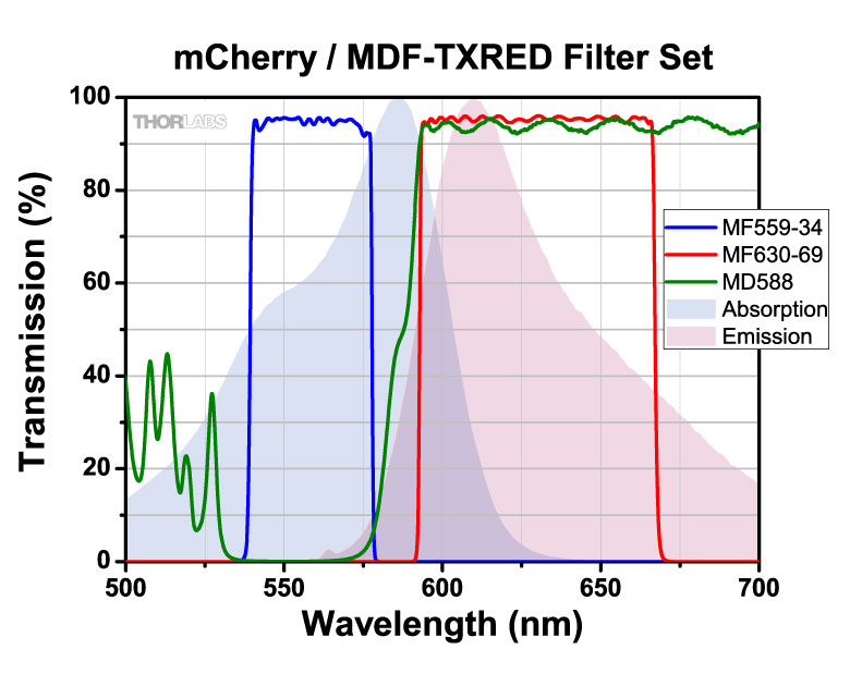
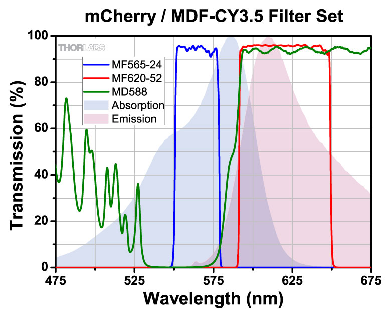
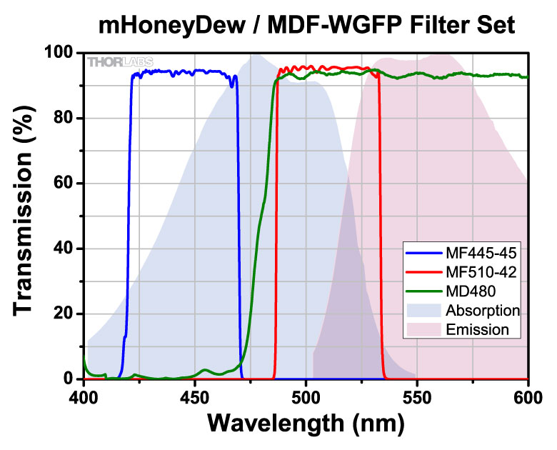
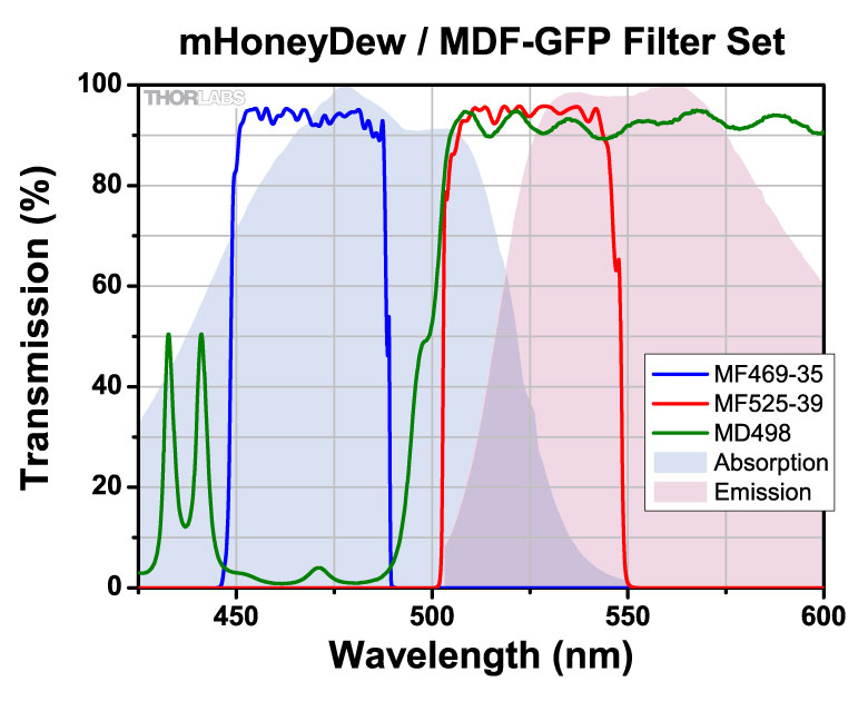
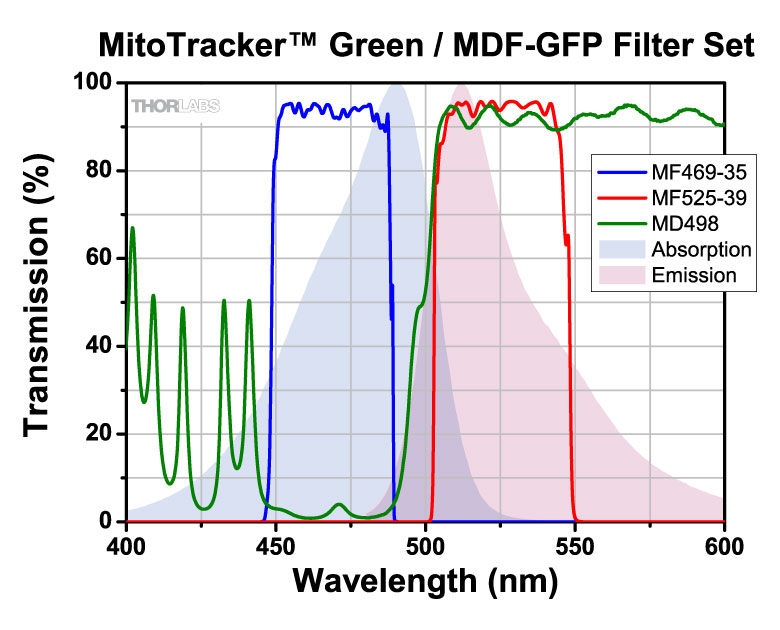
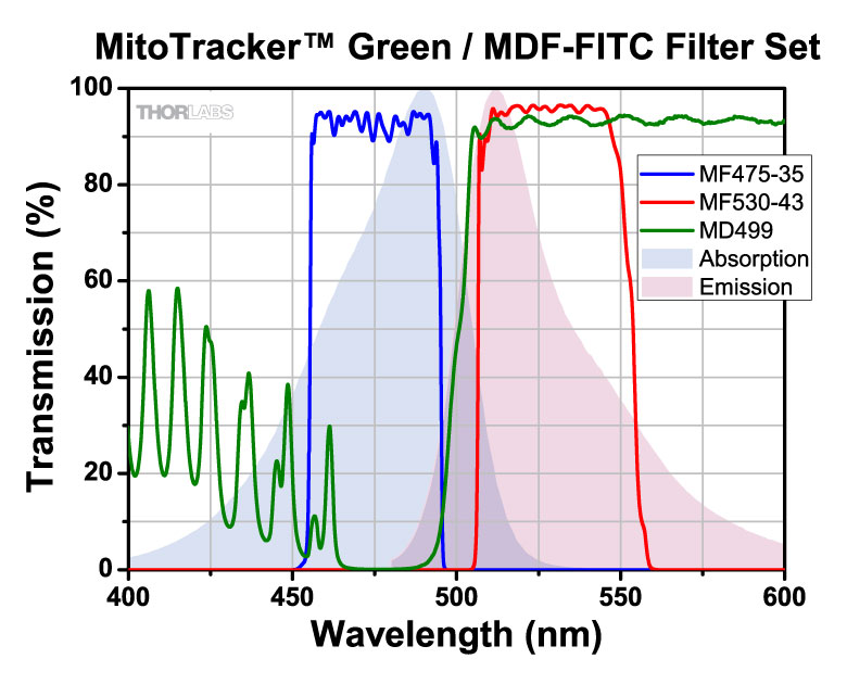
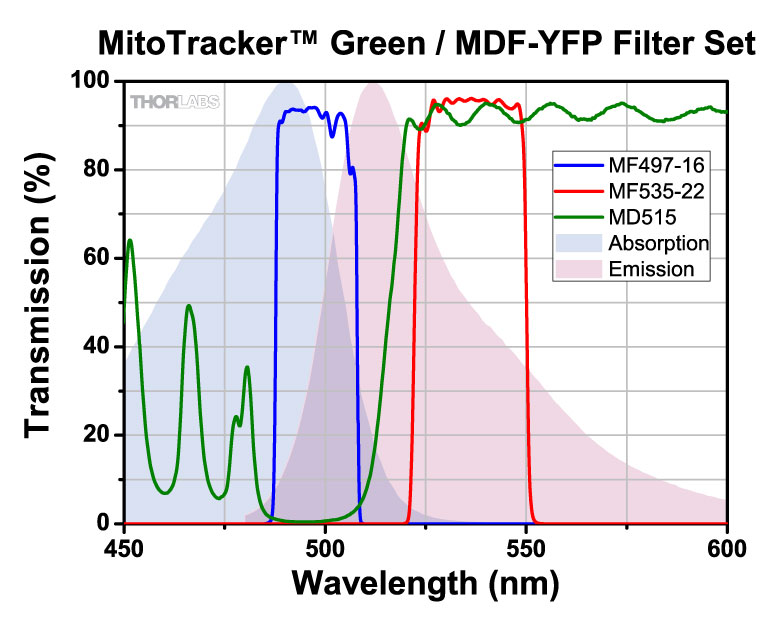
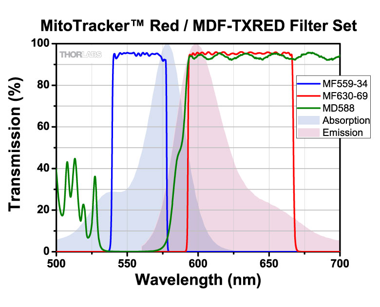
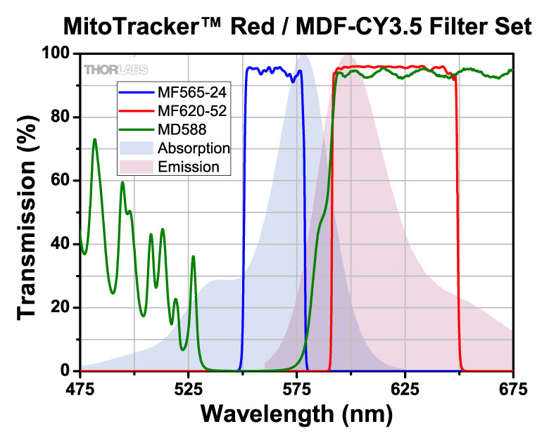
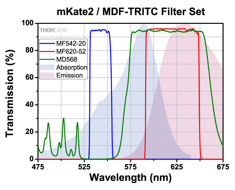
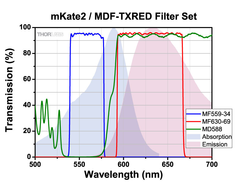
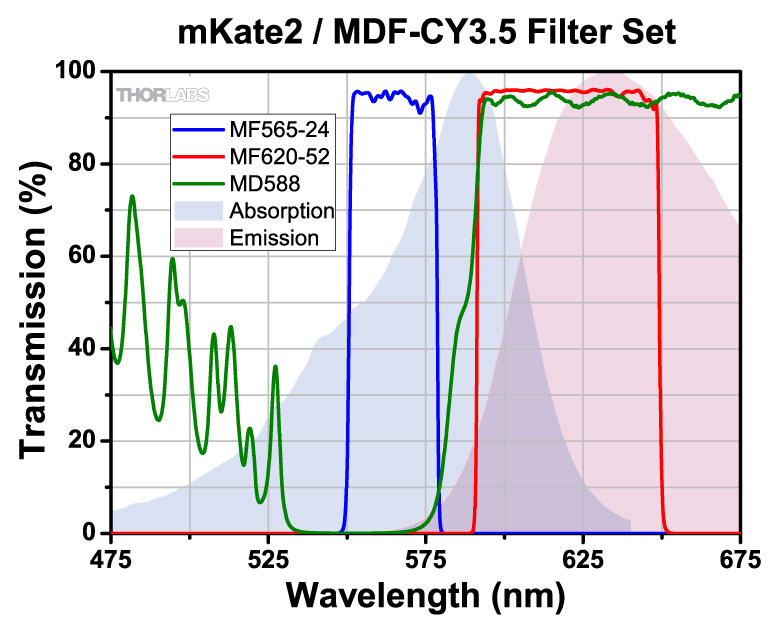
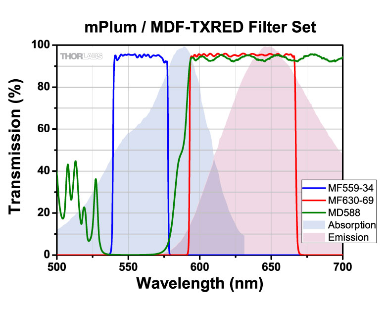
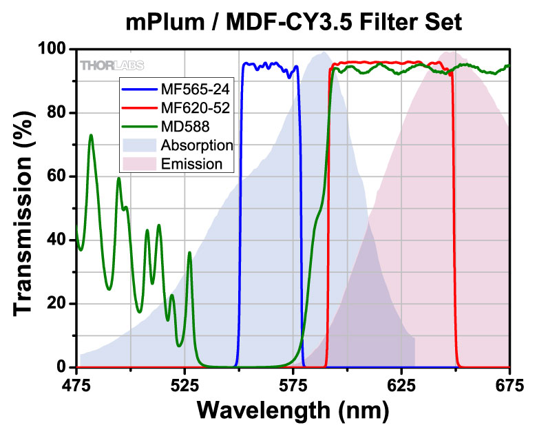
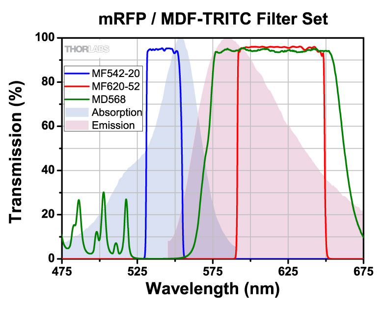
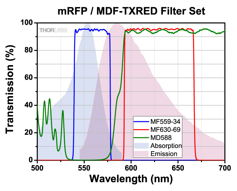
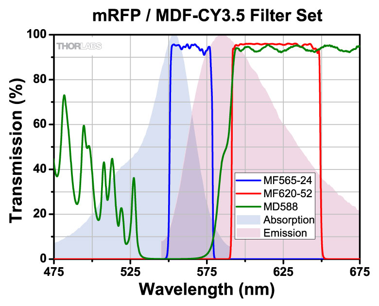
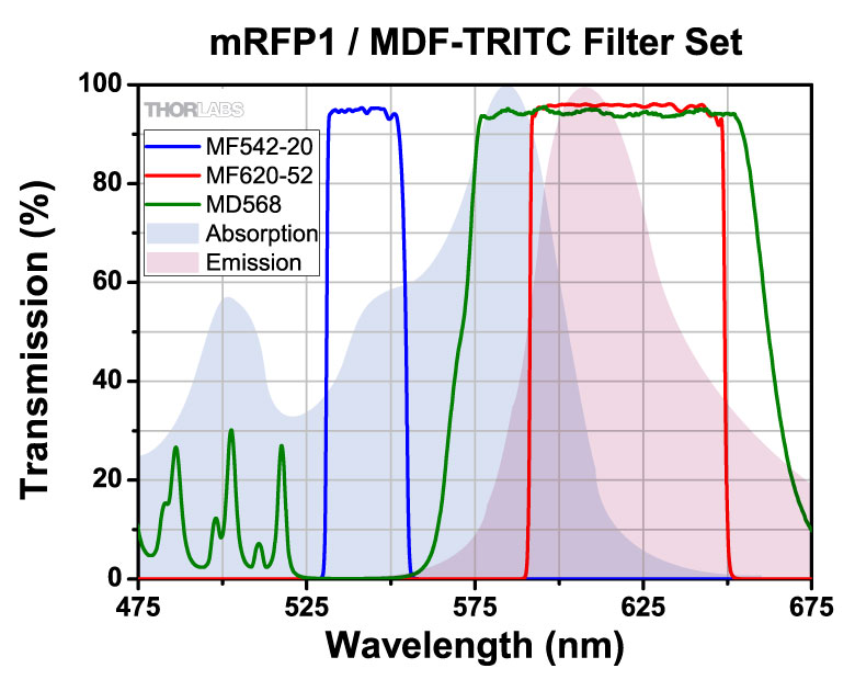
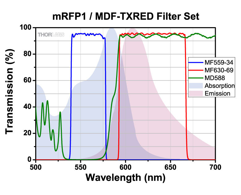
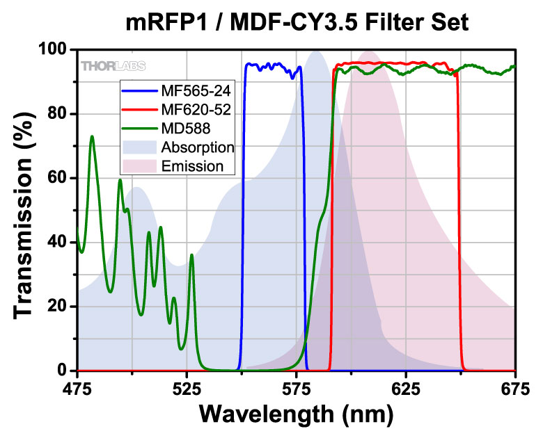
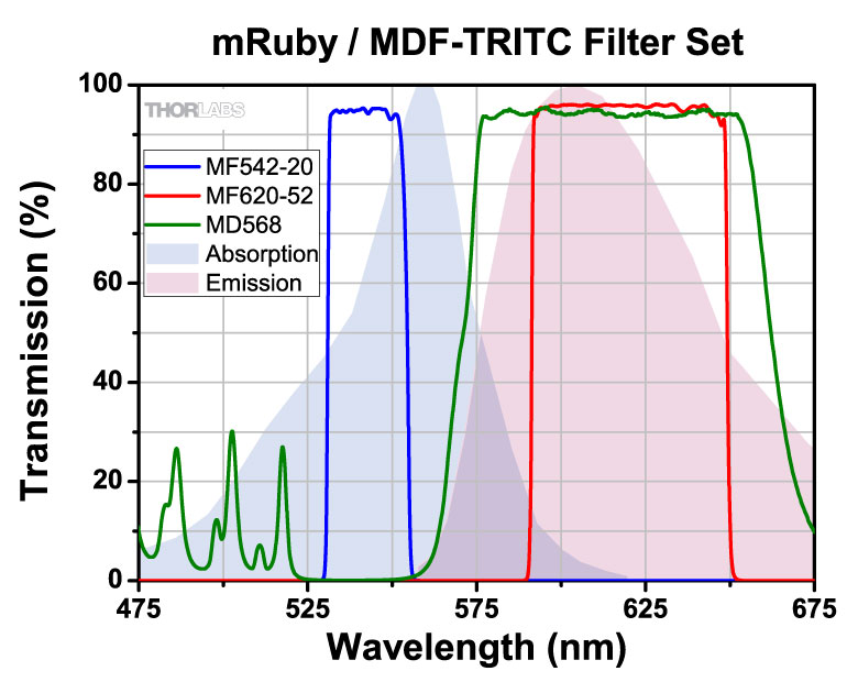
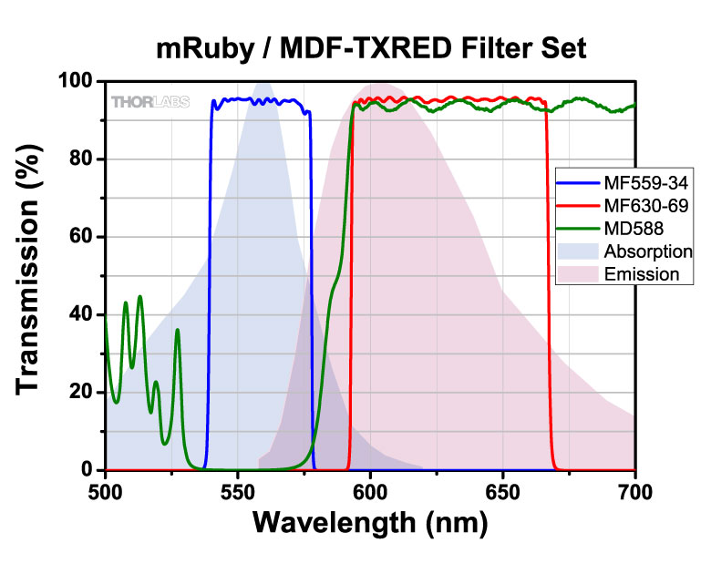
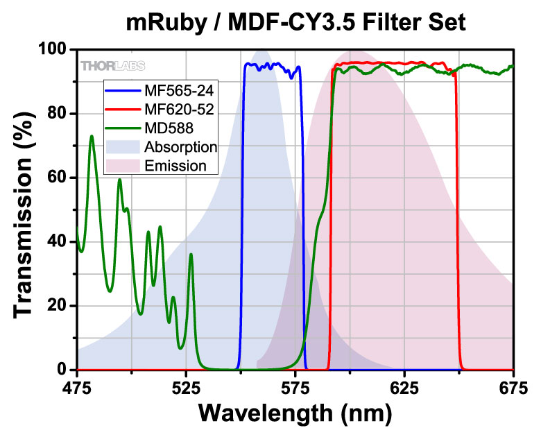
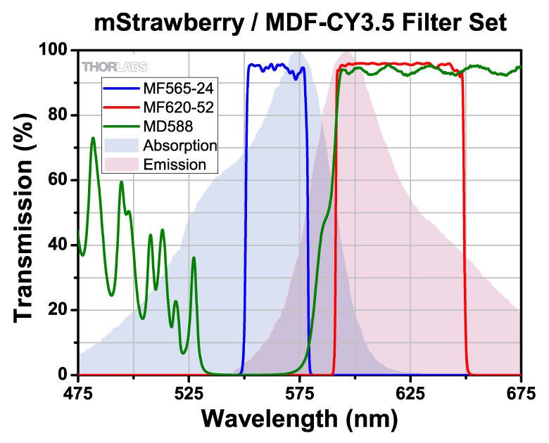
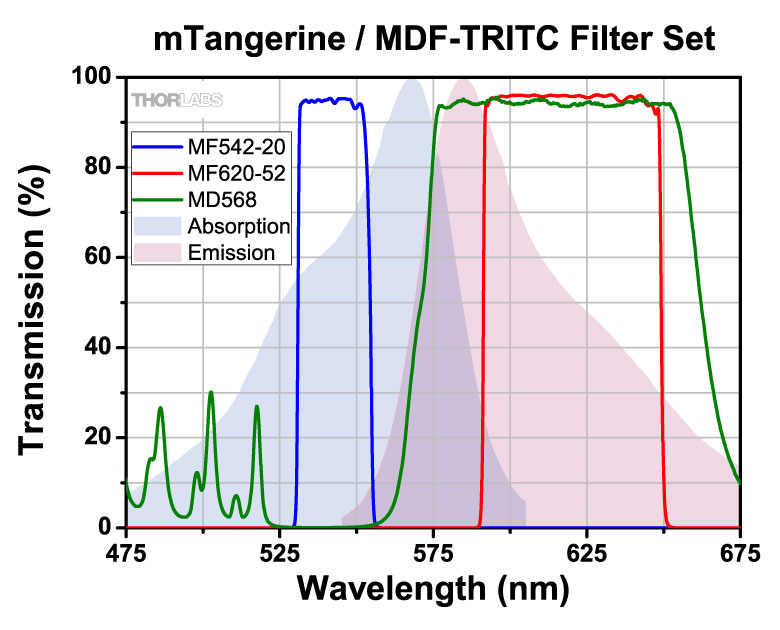
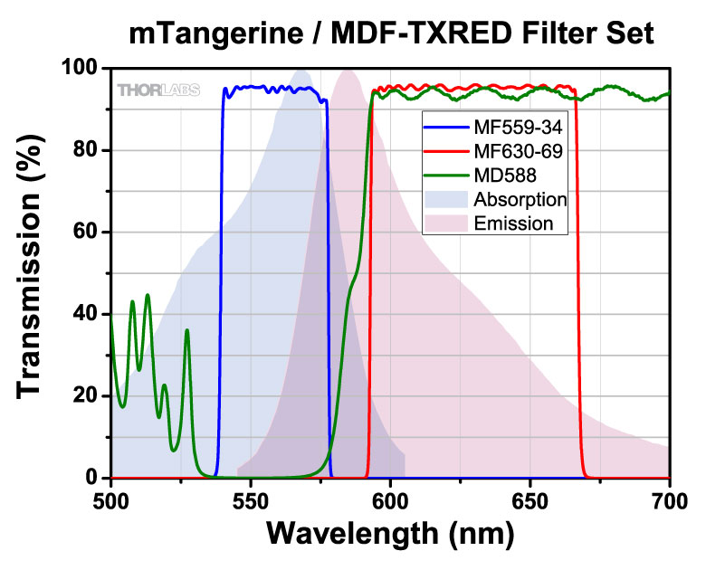
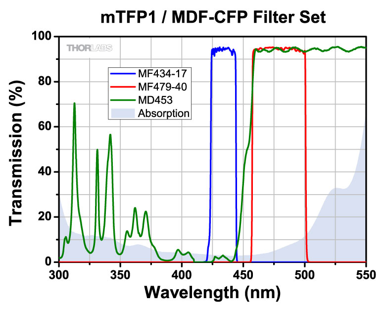
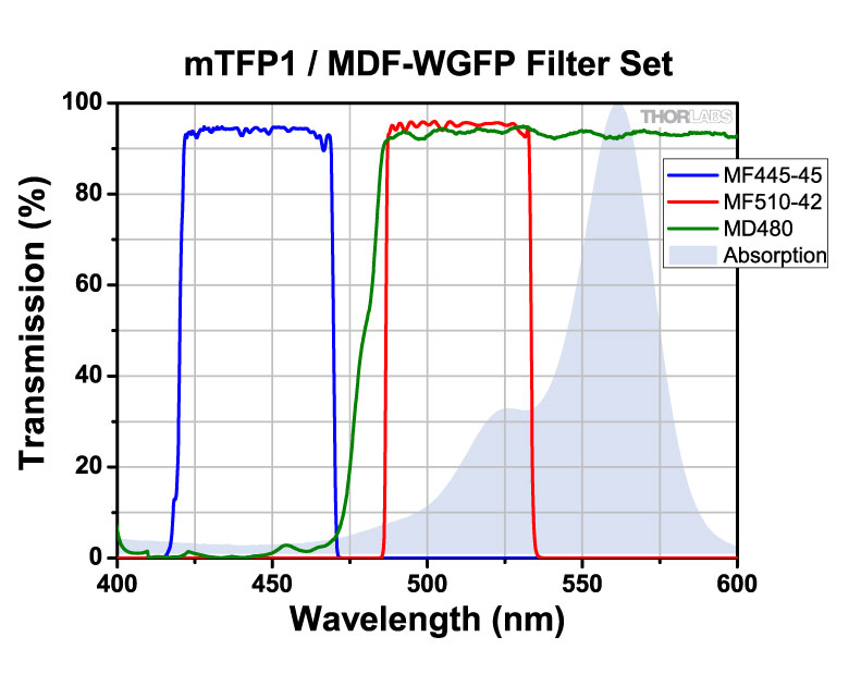
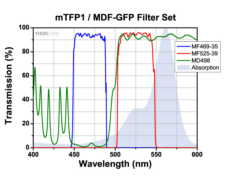
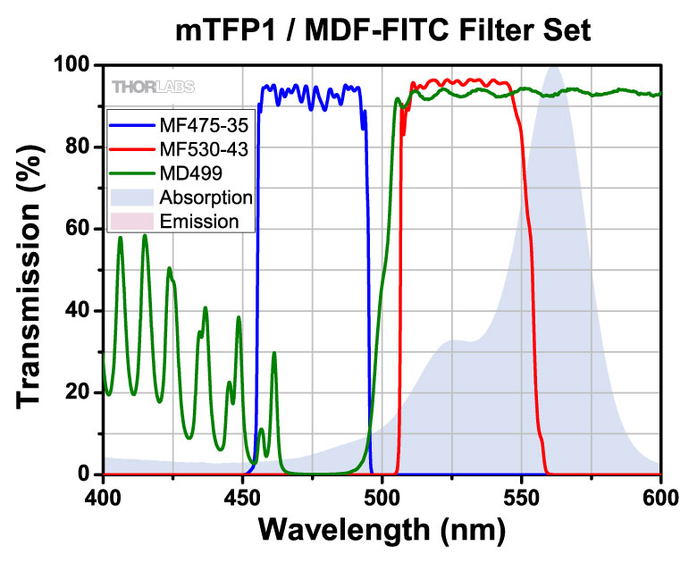
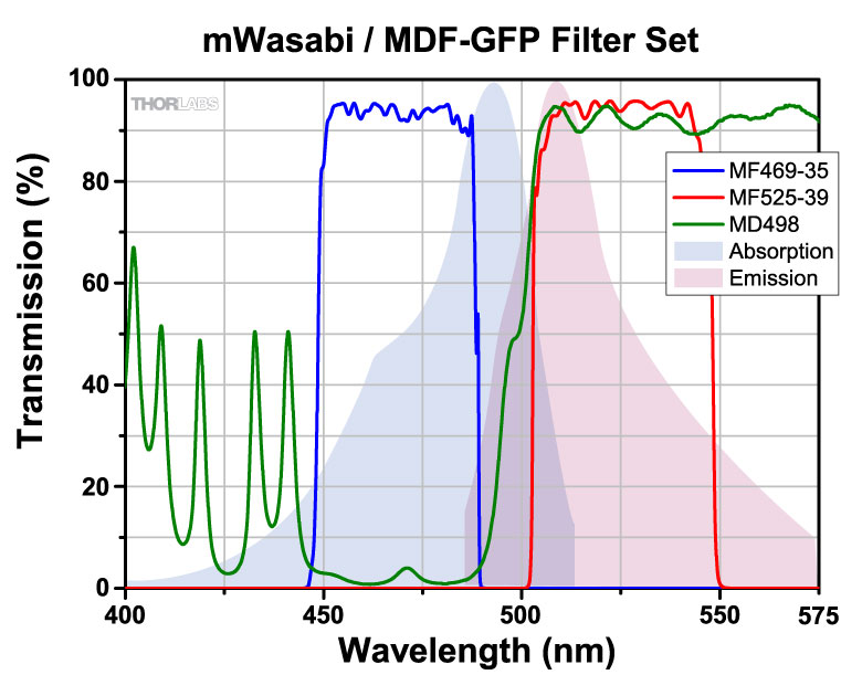
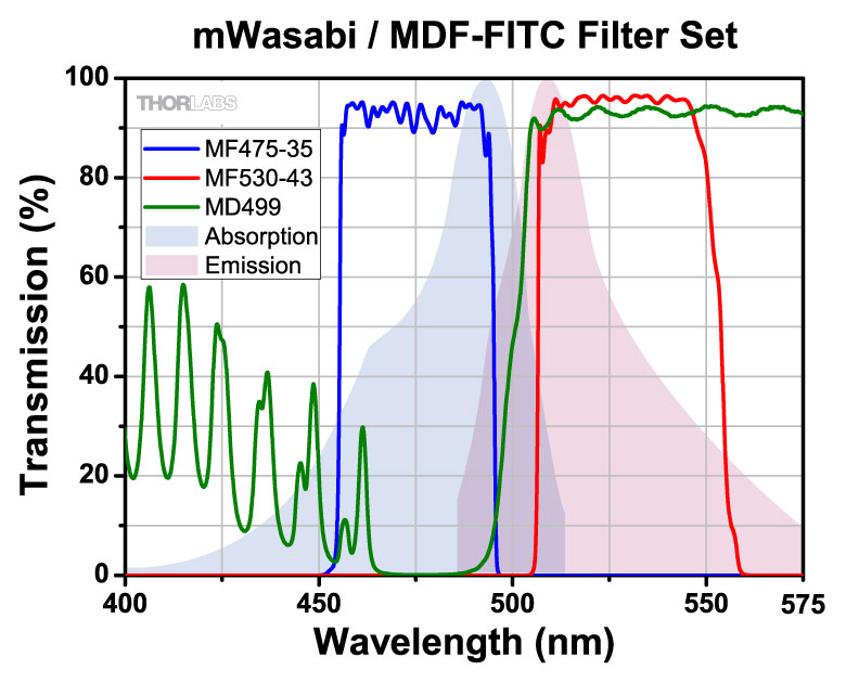
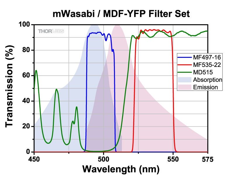
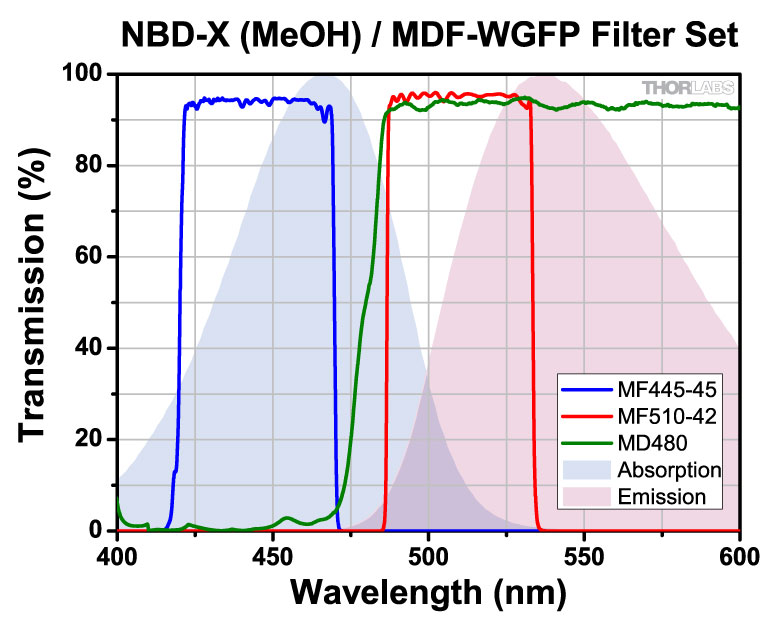
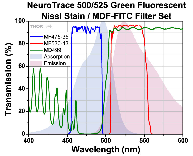
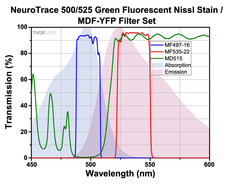
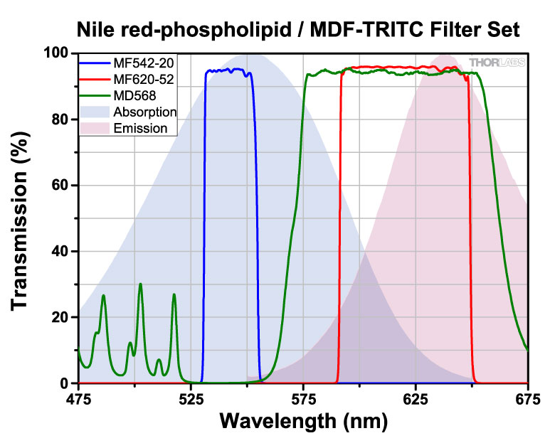
These excitation, emission, and dichroic filters are designed specifically for use in fluorescence imaging applications. They are fabricated at industry-standard dimensions that make them compatible with filter cubes from all major manufacturers. We offer individual filters and filter sets targeted at common fluorophores: BFP, CFP, WGFP, GFP, FITC, Alexa Fluor® 488, YFP, tdTomato, TRITC, Texas Red, mCherry, and Cyanine (CY3.5). In addition, the Fluorophores tab provides information on the alternative fluorophores suitable for these filters. These filters are also available pre-installed into our microscope filter cubes.
Filter Design
Our filters are manufactured to high-performance optical specifications and designed for durability. They are produced via multiple dielectric layers deposited on a high-precision, fused silica substrate. The substrate is ground and polished to ensure that the highest possible image quality is maintained. The resulting hard-coated optics consist of filter layers that are denser than those obtained from electron beam deposition techniques and that reduce water absorption while greatly enhancing the durability, stability, and performance of the filter. Each filter layer is monitored during growth to ensure minimal deviation from design specification thickness, ensuring overall high-quality filter performance.
Each filter is housed in a black anodized aluminum ring, which makes handling easier and enhances the blocking OD by limiting scattering. These filters can be mounted in our extensive line of filter mounts and wheels. As the mounts are not threaded, Ø1" retaining rings will be required to mount the filters in one of our internally-threaded SM1 lens tubes. For customers who wish to use these filters in Thorlabs, Olympus, or Nikon fluorescence microscopes, Thorlabs manufactures a family of Drop-In Microscope Filter Cubes.
Multimode Fiber Optic Filter Cubes
- Kinematic Fiber Optic Filter Cube for Fiber Photometry, Fluorescence Measurements, or Multimode Wwavelength Division Multiplexing (WDM)
- Three Ports with Multimode Fiber Collimators
- Achromatic: 400 - 700 nm
- Recommended for ≤0.5 NA Fibers, ≥Ø200 µm Core Diameter
- FC/PC 2.2 mm Wide Key Connector
- One Free-Space Port
- SM1 (1.035"-40) Internal Threads for Integration with a Power Meter or Ø1" Lens Tube
- Four 4-40 Tapped Holes Enable 30 mm Cage System Compatibility
- Includes One DFM1T1 Insert for Holding Fluorescence Filter Sets
- Easily Swap Cube Inserts with Different Mounted Optics
The FOFD3(/M)-A Kinematic Multimode Fiber Optic Filter Cube combines high-throughput, pre-aligned fiber collimators with the flexibility to quickly and repeatably exchange filters and dichroics for a variety of applications that require combining or separating light by wavelength. Three ports of the FOFD3(/M)-A filter cube have fiber collimators for connecting an LED or laser via mulitmode fibers. The collimators provide achromatic performance from 400 to 700 nm and are recommended to be used with ≥Ø200 µm, ≤0.5 NA mulitmode mode fibers. The single free-space port has internal SM1 (1.035"-40) threads, compatible with Ø1" lens tubes or many of Thorlabs' Avalanche Photodetectors. Three plastic FC bulkhead dust caps and one snap-on SM1 plastic dust cap are included, ensuring a light tight environment for low signals.
Alternatively, for those systems that require more flexibility, Thorlabs also offers Kinematic Fluorescence Filter Cubes with four free-space ports. High-NA Achromatic Collimators can be integrated into SM1-threaded ports of the filter cubes using an AD15F adapter. This provides the flexibility to easily change filter sets, and the ability to further customize the system, while requiring the user to carefully align the fiber collimators for maximum signal.
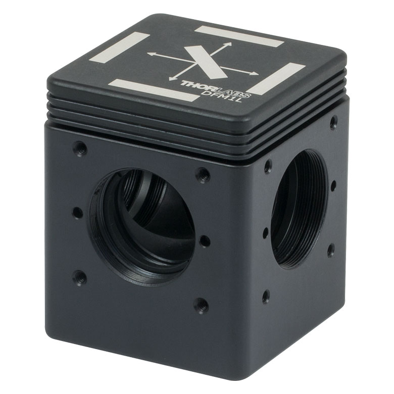
Click to Enlarge
DFM1L Kinematic Fluorescence Filter Cube
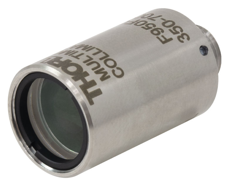
Click to Enlarge
F950FC-A Multimode Collimator
| Typical Fiber Photometry Filter and Cube Setup Components | ||
|---|---|---|
| Filter Cubes | ||
| Item # | Description | |
| FOFD3-A (FOFD3/M-A) | Kinematic Multimode Fiber Optic Filter Cube, 400 - 700 nm | |
| Input Filters | ||
| Item # | Description | Compatible Wavelengths |
| FBH405-10 | Excitation Filter | CWL = 405 nm |
| MF469-35 | GFP Excitation Filter | CWL = 469 nm |
| MD416 | BFP Dichroic Filter | Reflection Band: 360 nm - 407 nm Transmission Band: 425 nm - 575 nm |
| Output Filters | ||
| Item # | Description | Compatible Wavelengths |
| MF525-39 | GFP Emission Filter | CWL = 525 nm |
| DMSP490R | Shortpass Dichroic Mirror | 490 nm Cutoff |
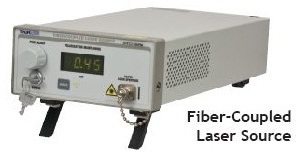
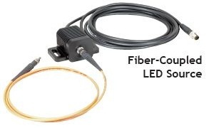
Light Sources
Thorlabs offers a variety of fiber-coupled light sources that can be used for in vivo stimulation. Our Fiber-Coupled LEDs offer a durable, economic solution with a variety of wavelength choices. Our Fiber-Coupled Lasers, Pigtailed Laser Diodes, and Benchtop Laser Diodes provide higher power at the cannula tip, and our Multichannel Light Sources offer a variety of wavelengths in a compact unit.
Click to Enlarge
Multimode Optical Fiber
Click to Enlarge
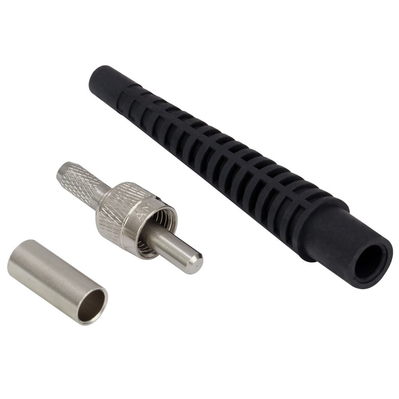
SMA905 Connector Components
Cable and Cannula Building Supplies
- Bare Optical Fiber, Ferrules, Tubing, Connectors, and Tools
- Build Custom Cannulae and Fiber Optic Patch Cables
- Connectorization Kit Provides all Necessary Tools
- Complete Connectorization Instructions Available for Download
Thorlabs stocks individual components for building custom fiber optic cannulae and patch cables, including optical fiber, ferrules, connectors, tubing, and connectorization tools. Our FN96A connectorization manual, which is free to download, gives clear instructions on how to add connectors to optical fiber.
| Quick Links | |||
|---|---|---|---|
| Single-Site Stimulation | |||
| One Light Source to One Cannula Implant | |||
| Multilateral Stimulation | |||
| One Light Source to Two Cannula Implants Using Rotary Joint Splitter | |||
| One or Two Light Sources to Two Cannula Implants | |||
| One Light Source to Seven Cannula Implants | |||
| Two Light Sources into One Dual-Core Cannula Implant | |||
| Illumination | |||
| Fiber-Coupled LEDs and Drivers | |||
Optogenetics Selection Guide
Thorlabs offers a wide range of optogenetics components; the compatibility of these products in select standard configurations is discussed in detail here. Please contact Technical Support for assistance with items outside the scope of this guide, including custom fiber components for optogenetics.
Single-Site Stimulation
One Light Source to One Cannula Implant
The most straightforward method for in vivo light stimulation of a specimen is to use a single fiber optic with a single LED light source. The single wavelength LED is powered by an LED driver, and then the illumination output is fiber-coupled into a patch cable, which connects to the implanted cannula. See the graphics and expandable compatibility tables below for the necessary patch cables and cannulae to create this setup. To choose the appropriate LED and driver, see below or the full web presentation.
Click on Each Component for More Information
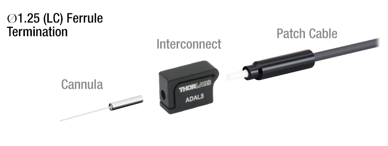
Click to See Ø1.25 mm (LC) Ferrule Compatible Patch Cables, Cannulae, and Interconnects
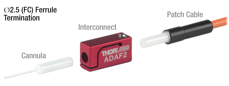
Click to See Ø2.5 mm (FC) Ferrule Compatible Patch Cables, Cannulae, and Interconnects
Multilateral Stimulation
The ability to accurately and simultaneously direct light to multiple locations within a specimen is desired for many types of optogenetics experiments. For example, bilateral stimulation techniques typically target neurons in two spatially separated regions in order to induce a desired behavior. In more complex experiments involving the simultaneous inhibition and stimulation of neurons, delivering light of two different monochromatic wavelengths within close proximity enables the user to perform these experiments without implanting multiple cannulae, which can increase stress on the specimen.
Multilateral stimulation can be achieved with several different configurations depending on the application requirements. The sections below illustrate examples of different configurations using Thorlabs' optogenetics products.
Option 1: One Light Source to Two Cannula Implants Using Rotary Joint Splitter
Thorlabs' RJ2 1x2 Rotary Joint Splitter is designed for optogenetics applications and is used to split light from a single input evenly between two outputs. The rotary joint interface allows connected patch cables to freely rotate, reducing the risk of fiber damage caused by a moving specimen. See the graphic and compatibility table below for the necessary cables and cannulae to create this setup. For LEDs and drivers, see below or the full web presentation.
Click to See Ø1.25 mm (LC) Ferrule Components Recommended for Use with RJ2 Rotary Joint Splitter
Click to See Ø2.5 mm (FC) Ferrule Components Recommended for Use with RJ2 Rotary Joint Splitter
Option 2: One or Two Light Sources to Two Cannula Implants
If the intent is for one LED source to connect to two cannulae for simultaneous light modulation, then a bifurcated fiber bundle can be used to split the light from the LED into each respective cannula. For dual wavelength stimulation (mixing two wavelengths in a single cannula) or a more controlled split ratio between cannula, one can use a multimode coupler to connect one or two LEDs to the cannulae. If one cable end is left unused, the spare coupler cable end may be terminated by a light trap. See the graphic and compatibility table below for the necessary cables and cannulae to create this setup. For LEDs and drivers, see below or the full web presentation.
Click on Each Component Below for More Information
Option 3: One Light Sources to Seven Cannula Implants
If the intent is for one LED source to connect to seven cannulae for simultaneous light modulation, then a 1-to-7 fiber bundle can be used to split the light from the LED into each respective cannula. See the graphic and compatibility table below for the necessary cables and cannulae to create this setup. For LEDs and drivers, see below or the full web presentation.
Click on Each Component Below for More Information
Two Light Sources into One Dual-Core Cannula Implant
For bilateral stimulation applications where the two cannulas need to be placed in close proximity (within ~1 mm), Thorlabs offers dual-core patch cables and cannulae that are designed for this specific application. Each core is driven by a separate light source, enabling users to stimulate and/or supress nerve cells in the same region of the specimen. See the graphic and compatibility table below for the necessary cables and cannulae to create this setup. For LEDs and drivers, see below or the full web presentation.
Click on Each Component for More Information
| Part Selection Table (Click Links for Item Description Popup) | |||||||||
|---|---|---|---|---|---|---|---|---|---|
| Common Fiber Properties | |||||||||
| Core Diameter | 200 µm | ||||||||
| Wavelength Range | 400 - 2200 nm | ||||||||
| NA | 0.39 | ||||||||
| Fiber Type | FT200EMT | ||||||||
| Ferrule Stylea | FC (Ø2.5 mm) | ||||||||
| Dual-Core Patch Cable | FC/PC Input | BFY32FL1 | |||||||
| SMA905 Input | BFY32SL1 | ||||||||
| Compatible Mating Sleeve/Interconnect | ADAF1 ADAF2 ADAF4-5 |
||||||||
| Dual-Core Fiber Optic Cannulaec | Stainless Steel | CFM32L10 CFM32L20 |
|||||||
| LED Item # | Wavelengtha | Typical Opsin | Output Powerb | Color |
|---|---|---|---|---|
| M385F1c | 385 nm | EBFP, moxBFP | 10.7 mW | UV |
| M405F1c | 405 nm | mmilCFP, hcriGFP | 3.7 mW | UV |
| M430F1 | 430 nm | ChR2 | 7.5 mW | Violet |
| M455F3 | 455 nm | ChIEF, bPAC | 24.5 mW | Royal Blue |
| M505F3 | 505 nm | ChRGR, Opto-α1AR, Opto-β2AR | 11.7 mW | Cyan |
| M530F2 | 530 nm | C1V1, VChR1 | 9.6 mW | Green |
| M565F3 | 565 nm | Arch, VChR1-SFO | 13.5 mW | Lime |
| M595F2 | 595 nm | ChR2-SFO, eNpHR3.0 | 11.5 mW | Amber |
| M625F2 | 625 nm | ReChR | 17.5 mW | Red |
Illumination
Click to Enlarge
M405F1
Fiber-Coupled LEDs and Drivers
Our fiber-coupled LEDs are ideal light sources for optogenetics applications. They feature a variety of wavelength choices and a convenient interconnection to optogenetics patch cables. Thorlabs offers fiber-coupled LEDs with nominal wavelengths ranging from 280 nm to 1050 nm. See the table to the right for the LEDs with the most popular wavelengths for optogenetics. A table of compatible LED drivers can be viewed by clicking below.

Custom Fiber Optic Cannula
Thorlabs offers custom cannulae with the following options. Place a quote request through the following form to receive a quote for your custom cannula order.
| Quick Links |
|---|
| Damage at the Air / Glass Interface |
| Intrinsic Damage Threshold |
| Preparation and Handling of Optical Fibers |
Laser-Induced Damage in Silica Optical Fibers
The following tutorial details damage mechanisms relevant to unterminated (bare) fiber, terminated optical fiber, and other fiber components from laser light sources. These mechanisms include damage that occurs at the air / glass interface (when free-space coupling or when using connectors) and in the optical fiber itself. A fiber component, such as a bare fiber, patch cable, or fused coupler, may have multiple potential avenues for damage (e.g., connectors, fiber end faces, and the device itself). The maximum power that a fiber can handle will always be limited by the lowest limit of any of these damage mechanisms.
While the damage threshold can be estimated using scaling relations and general rules, absolute damage thresholds in optical fibers are very application dependent and user specific. Users can use this guide to estimate a safe power level that minimizes the risk of damage. Following all appropriate preparation and handling guidelines, users should be able to operate a fiber component up to the specified maximum power level; if no maximum is specified for a component, users should abide by the "practical safe level" described below for safe operation of the component. Factors that can reduce power handling and cause damage to a fiber component include, but are not limited to, misalignment during fiber coupling, contamination of the fiber end face, or imperfections in the fiber itself. For further discussion about an optical fiber’s power handling abilities for a specific application, please contact Thorlabs’ Tech Support.
Click to Enlarge
Undamaged Fiber End
Click to Enlarge
Damaged Fiber End
Damage at the Air / Glass Interface
There are several potential damage mechanisms that can occur at the air / glass interface. Light is incident on this interface when free-space coupling or when two fibers are mated using optical connectors. High-intensity light can damage the end face leading to reduced power handling and permanent damage to the fiber. For fibers terminated with optical connectors where the connectors are fixed to the fiber ends using epoxy, the heat generated by high-intensity light can burn the epoxy and leave residues on the fiber facet directly in the beam path.
| Estimated Optical Power Densities on Air / Glass Interfacea | ||
|---|---|---|
| Type | Theoretical Damage Thresholdb | Practical Safe Levelc |
| CW (Average Power) |
~1 MW/cm2 | ~250 kW/cm2 |
| 10 ns Pulsed (Peak Power) |
~5 GW/cm2 | ~1 GW/cm2 |
Damage Mechanisms on the Bare Fiber End Face
Damage mechanisms on a fiber end face can be modeled similarly to bulk optics, and industry-standard damage thresholds for UV Fused Silica substrates can be applied to silica-based fiber. However, unlike bulk optics, the relevant surface areas and beam diameters involved at the air / glass interface of an optical fiber are very small, particularly for coupling into single mode (SM) fiber. therefore, for a given power density, the power incident on the fiber needs to be lower for a smaller beam diameter.
The table to the right lists two thresholds for optical power densities: a theoretical damage threshold and a "practical safe level". In general, the theoretical damage threshold represents the estimated maximum power density that can be incident on the fiber end face without risking damage with very good fiber end face and coupling conditions. The "practical safe level" power density represents minimal risk of fiber damage. Operating a fiber or component beyond the practical safe level is possible, but users must follow the appropriate handling instructions and verify performance at low powers prior to use.
Calculating the Effective Area for Single Mode Fibers
The effective area for single mode (SM) fiber is defined by the mode field diameter (MFD), which is the cross-sectional area through which light propagates in the fiber; this area includes the fiber core and also a portion of the cladding. To achieve good efficiency when coupling into a single mode fiber, the diameter of the input beam must match the MFD of the fiber.
As an example, SM400 single mode fiber has a mode field diameter (MFD) of ~Ø3 µm operating at 400 nm, while the MFD for SMF-28 Ultra single mode fiber operating at 1550 nm is Ø10.5 µm. The effective area for these fibers can be calculated as follows:
SM400 Fiber: Area = Pi x (MFD/2)2 = Pi x (1.5 µm)2 = 7.07 µm2 = 7.07 x 10⁻⁸ cm2
SMF-28 Ultra Fiber: Area = Pi x (MFD/2)2 = Pi x (5.25 µm)2 = 86.6 µm2 = 8.66 x 10⁻⁷ cm2
To estimate the power level that a fiber facet can handle, the power density is multiplied by the effective area. Please note that this calculation assumes a uniform intensity profile, but most laser beams exhibit a Gaussian-like shape within single mode fiber, resulting in a higher power density at the center of the beam compared to the edges. Therefore, these calculations will slightly overestimate the power corresponding to the damage threshold or the practical safe level. Using the estimated power densities assuming a CW light source, we can determine the corresponding power levels as:
SM400 Fiber: 7.07 x 10⁻⁸ cm2 x 1 MW/cm2 = 7.1 x 10⁻⁸ MW = 71 mW (Theoretical Damage Threshold)
7.07 x 10⁻⁸ cm2 x 250 kW/cm2 = 1.8 x 10⁻⁵ kW = 18 mW (Practical Safe Level)
SMF-28 Ultra Fiber: 8.66 x 10⁻⁷ cm2 x 1 MW/cm2 = 8.7 x 10⁻⁷ MW = 870 mW (Theoretical Damage Threshold)
8.66 x 10⁻⁷ cm2 x 250 kW/cm2 = 2.1 x 10⁻⁴ kW = 210 mW (Practical Safe Level)
Effective Area of Multimode Fibers
The effective area of a multimode (MM) fiber is defined by the core diameter, which is typically far larger than the MFD of an SM fiber. For optimal coupling, Thorlabs recommends focusing a beam to a spot roughly 70 - 80% of the core diameter. The larger effective area of MM fibers lowers the power density on the fiber end face, allowing higher optical powers (typically on the order of kilowatts) to be coupled into multimode fiber without damage.
Damage Mechanisms Related to Ferrule / Connector Termination
 Click to Enlarge
Plot showing approximate input power that can be incident on a single mode silica optical fiber with a termination. Each line shows the estimated power level due to a specific damage mechanism. The maximum power handling is limited by the lowest power level from all relevant damage mechanisms (indicated by a solid line).
Fibers terminated with optical connectors have additional power handling considerations. Fiber is typically terminated using epoxy to bond the fiber to a ceramic or steel ferrule. When light is coupled into the fiber through a connector, light that does not enter the core and propagate down the fiber is scattered into the outer layers of the fiber, into the ferrule, and the epoxy used to hold the fiber in the ferrule. If the light is intense enough, it can burn the epoxy, causing it to vaporize and deposit a residue on the face of the connector. This results in localized absorption sites on the fiber end face that reduce coupling efficiency and increase scattering, causing further damage.
For several reasons, epoxy-related damage is dependent on the wavelength. In general, light scatters more strongly at short wavelengths than at longer wavelengths. Misalignment when coupling is also more likely due to the small MFD of short-wavelength SM fiber that also produces more scattered light.
To minimize the risk of burning the epoxy, fiber connectors can be constructed to have an epoxy-free air gap between the optical fiber and ferrule near the fiber end face. Our high-power multimode fiber patch cables use connectors with this design feature.
Determining Power Handling with Multiple Damage Mechanisms
When fiber cables or components have multiple avenues for damage (e.g., fiber patch cables), the maximum power handling is always limited by the lowest damage threshold that is relevant to the fiber component. In general, this represents the highest input power that can be incident on the patch cable end face and not the coupled output power.
As an illustrative example, the graph to the right shows an estimate of the power handling limitations of a single mode fiber patch cable due to damage to the fiber end face and damage via an optical connector. The total input power handling of a terminated fiber at a given wavelength is limited by the lower of the two limitations at any given wavelength (indicated by the solid lines). A single mode fiber operating at around 488 nm is primarily limited by damage to the fiber end face (blue solid line), but fibers operating at 1550 nm are limited by damage to the optical connector (red solid line).
In the case of a multimode fiber, the effective mode area is defined by the core diameter, which is larger than the effective mode area for SM fiber. This results in a lower power density on the fiber end face and allows higher optical powers (on the order of kilowatts) to be coupled into the fiber without damage (not shown in graph). However, the damage limit of the ferrule / connector termination remains unchanged and as a result, the maximum power handling for a multimode fiber is limited by the ferrule and connector termination.
Please note that these are rough estimates of power levels where damage is very unlikely with proper handling and alignment procedures. It is worth noting that optical fibers are frequently used at power levels above those described here. However, these applications typically require expert users and testing at lower powers first to minimize risk of damage. Even still, optical fiber components should be considered a consumable lab supply if used at high power levels.
Intrinsic Damage Threshold
In addition to damage mechanisms at the air / glass interface, optical fibers also display power handling limitations due to damage mechanisms within the optical fiber itself. These limitations will affect all fiber components as they are intrinsic to the fiber itself. Two categories of damage within the fiber are damage from bend losses and damage from photodarkening.
Bend Losses
Bend losses occur when a fiber is bent to a point where light traveling in the core is incident on the core/cladding interface at an angle higher than the critical angle, making total internal reflection impossible. Under these circumstances, light escapes the fiber, often in a localized area. The light escaping the fiber typically has a high power density, which burns the fiber coating as well as any surrounding furcation tubing.
A special category of optical fiber, called double-clad fiber, can reduce the risk of bend-loss damage by allowing the fiber’s cladding (2nd layer) to also function as a waveguide in addition to the core. By making the critical angle of the cladding/coating interface higher than the critical angle of the core/clad interface, light that escapes the core is loosely confined within the cladding. It will then leak out over a distance of centimeters or meters instead of at one localized spot within the fiber, minimizing the risk of damage. Thorlabs manufactures and sells 0.22 NA double-clad multimode fiber, which boasts very high, megawatt range power handling.
Photodarkening
A second damage mechanism, called photodarkening or solarization, can occur in fibers used with ultraviolet or short-wavelength visible light, particularly those with germanium-doped cores. Fibers used at these wavelengths will experience increased attenuation over time. The mechanism that causes photodarkening is largely unknown, but several fiber designs have been developed to mitigate it. For example, fibers with a very low hydroxyl ion (OH) content have been found to resist photodarkening and using other dopants, such as fluorine, can also reduce photodarkening.
Even with the above strategies in place, all fibers eventually experience photodarkening when used with UV or short-wavelength light, and thus, fibers used at these wavelengths should be considered consumables.
Preparation and Handling of Optical Fibers
General Cleaning and Operation Guidelines
These general cleaning and operation guidelines are recommended for all fiber optic products. Users should still follow specific guidelines for an individual product as outlined in the support documentation or manual. Damage threshold calculations only apply when all appropriate cleaning and handling procedures are followed.
-
All light sources should be turned off prior to installing or integrating optical fibers (terminated or bare). This ensures that focused beams of light are not incident on fragile parts of the connector or fiber, which can possibly cause damage.
-
The power-handling capability of an optical fiber is directly linked to the quality of the fiber/connector end face. Always inspect the fiber end prior to connecting the fiber to an optical system. The fiber end face should be clean and clear of dirt and other contaminants that can cause scattering of coupled light. Bare fiber should be cleaved prior to use and users should inspect the fiber end to ensure a good quality cleave is achieved.
-
If an optical fiber is to be spliced into the optical system, users should first verify that the splice is of good quality at a low optical power prior to high-power use. Poor splice quality may increase light scattering at the splice interface, which can be a source of fiber damage.
-
Users should use low power when aligning the system and optimizing coupling; this minimizes exposure of other parts of the fiber (other than the core) to light. Damage from scattered light can occur if a high power beam is focused on the cladding, coating, or connector.
Tips for Using Fiber at Higher Optical Power
Optical fibers and fiber components should generally be operated within safe power level limits, but under ideal conditions (very good optical alignment and very clean optical end faces), the power handling of a fiber component may be increased. Users must verify the performance and stability of a fiber component within their system prior to increasing input or output power and follow all necessary safety and operation instructions. The tips below are useful suggestions when considering increasing optical power in an optical fiber or component.
-
Splicing a fiber component into a system using a fiber splicer can increase power handling as it minimizes possibility of air/fiber interface damage. Users should follow all appropriate guidelines to prepare and make a high-quality fiber splice. Poor splices can lead to scattering or regions of highly localized heat at the splice interface that can damage the fiber.
-
After connecting the fiber or component, the system should be tested and aligned using a light source at low power. The system power can be ramped up slowly to the desired output power while periodically verifying all components are properly aligned and that coupling efficiency is not changing with respect to optical launch power.
-
Bend losses that result from sharply bending a fiber can cause light to leak from the fiber in the stressed area. When operating at high power, the localized heating that can occur when a large amount of light escapes a small localized area (the stressed region) can damage the fiber. Avoid disturbing or accidently bending fibers during operation to minimize bend losses.
-
Users should always choose the appropriate optical fiber for a given application. For example, large-mode-area fibers are a good alternative to standard single mode fibers in high-power applications as they provide good beam quality with a larger MFD, decreasing the power density on the air/fiber interface.
-
Step-index silica single mode fibers are normally not used for ultraviolet light or high-peak-power pulsed applications due to the high spatial power densities associated with these applications.
| Keya | |
|---|---|
 |
Acceptable - Actual performance depends on individual experimental conditions. |
|
Compatible - Ideal, or nearly ideal, performance under most experimental conditions. |
 |
Optimized - Optimal performance under all experimental conditions. |
a. Absorption and emission spectra are unavailable if any  is red.
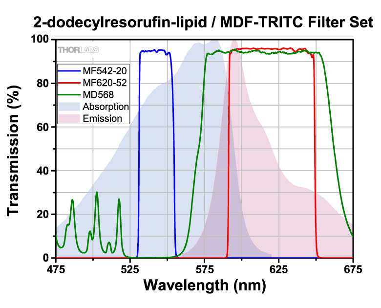
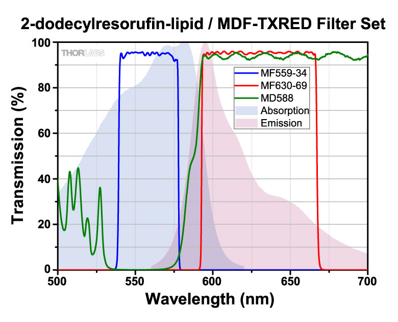
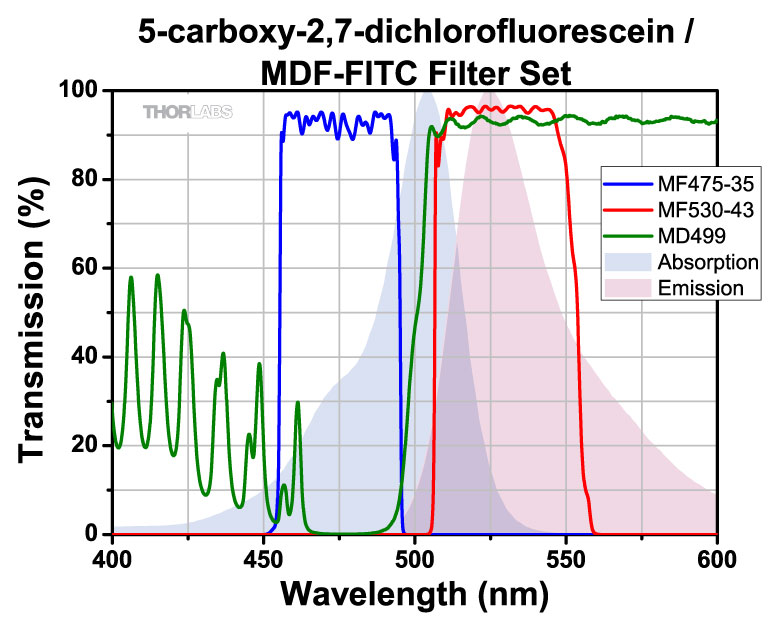
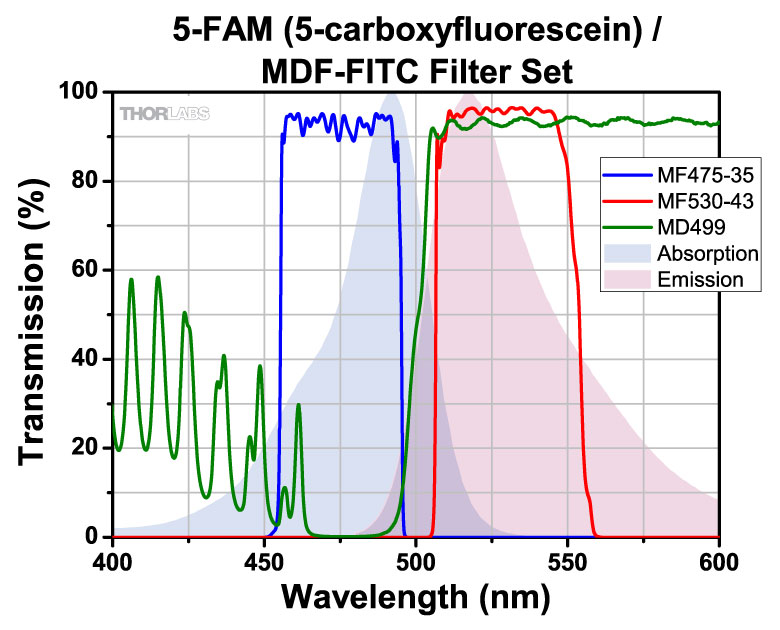
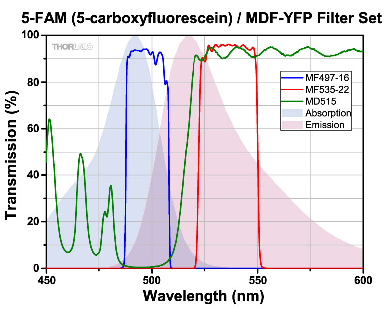
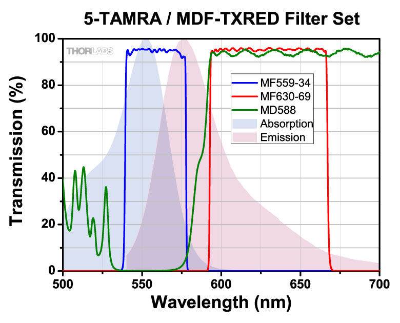
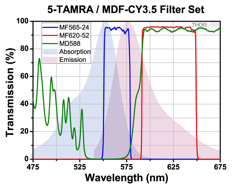
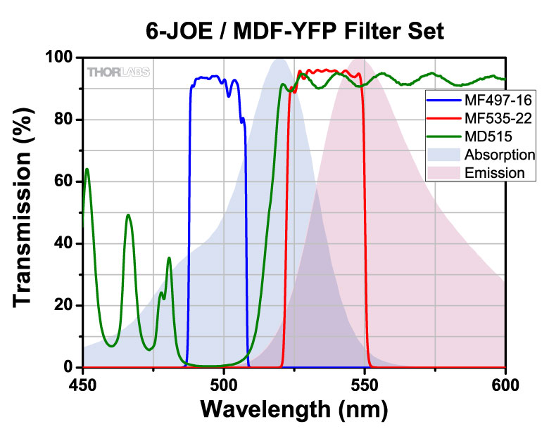
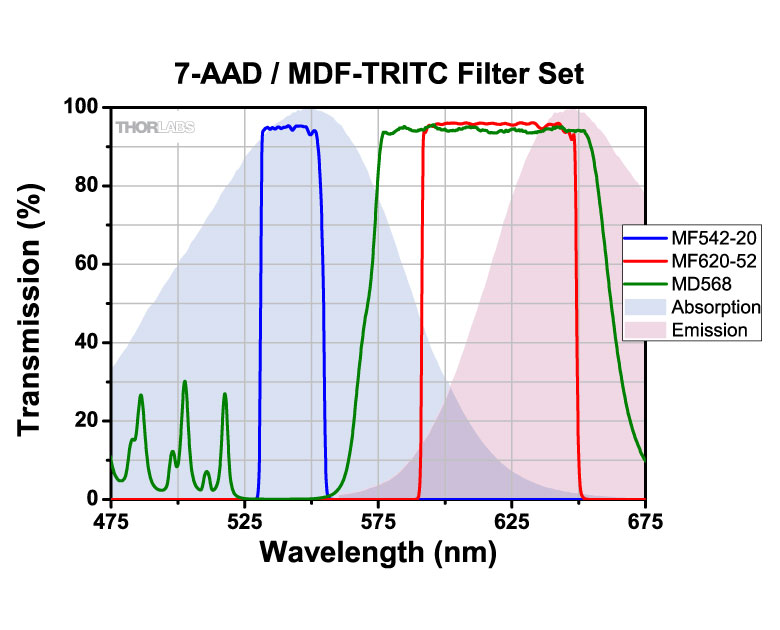
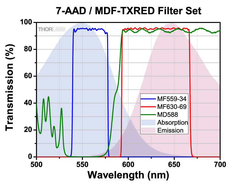
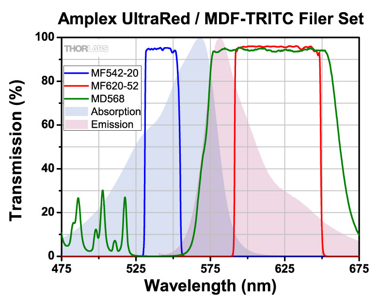
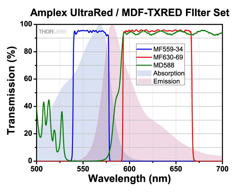
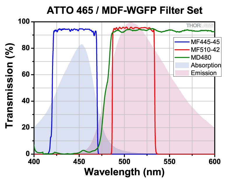
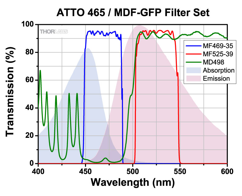
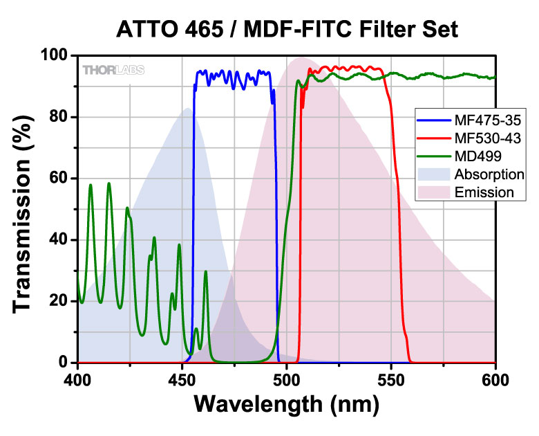
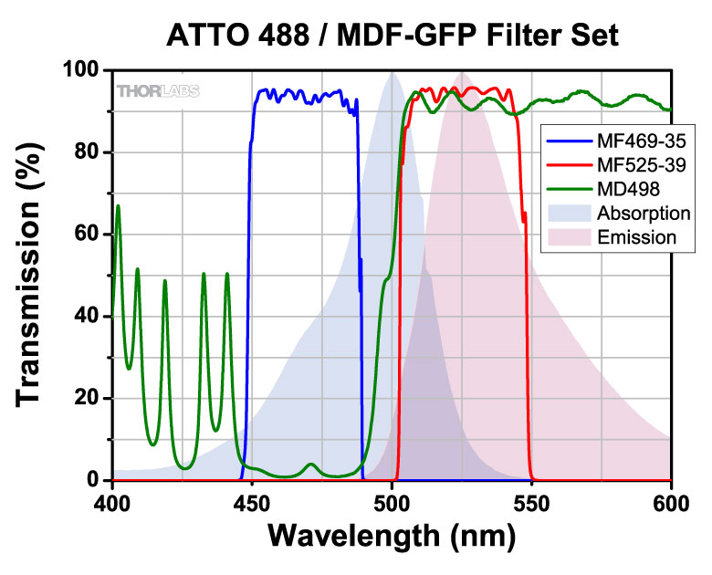
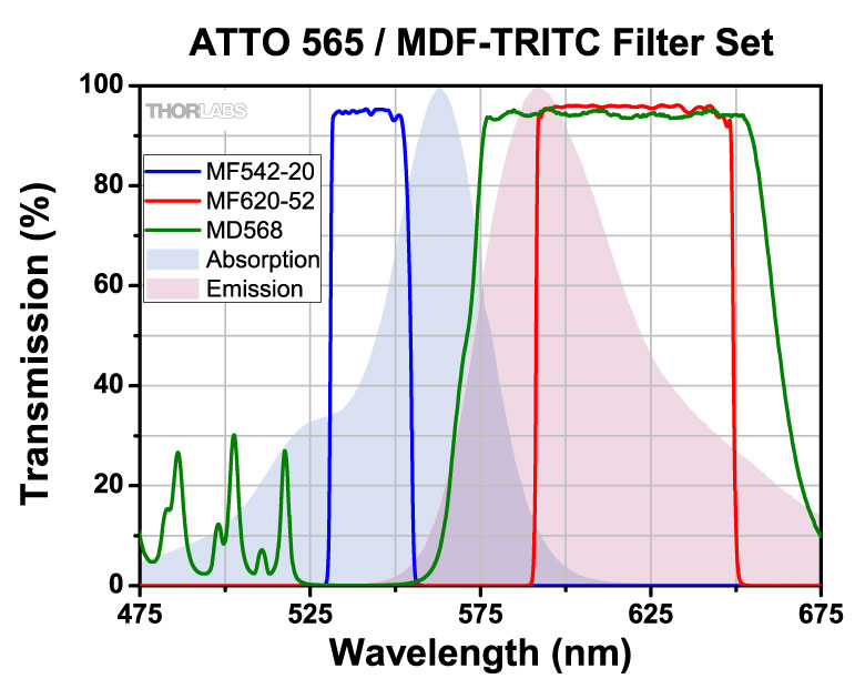
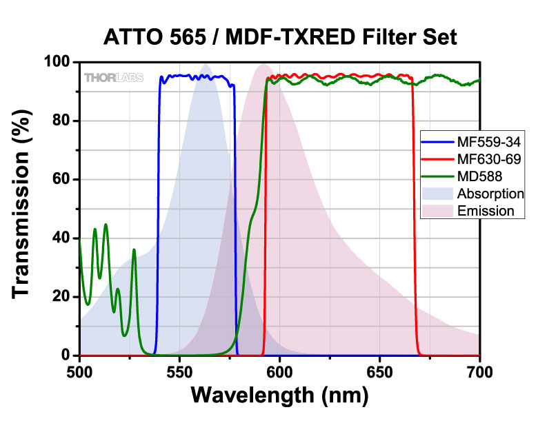
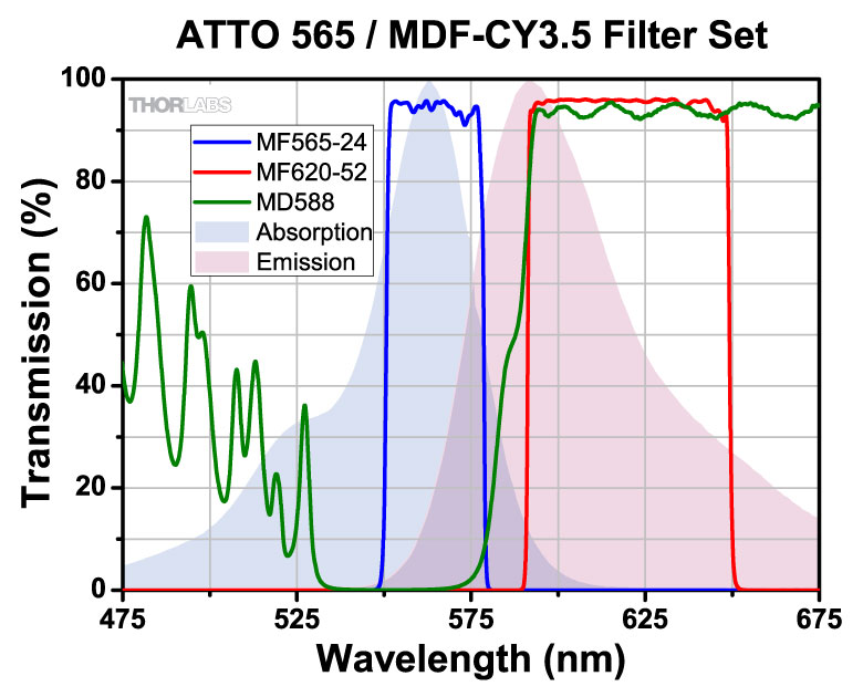
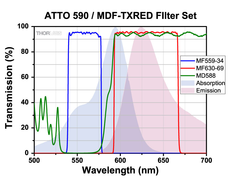
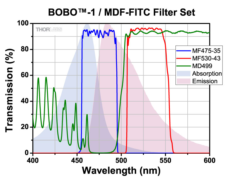
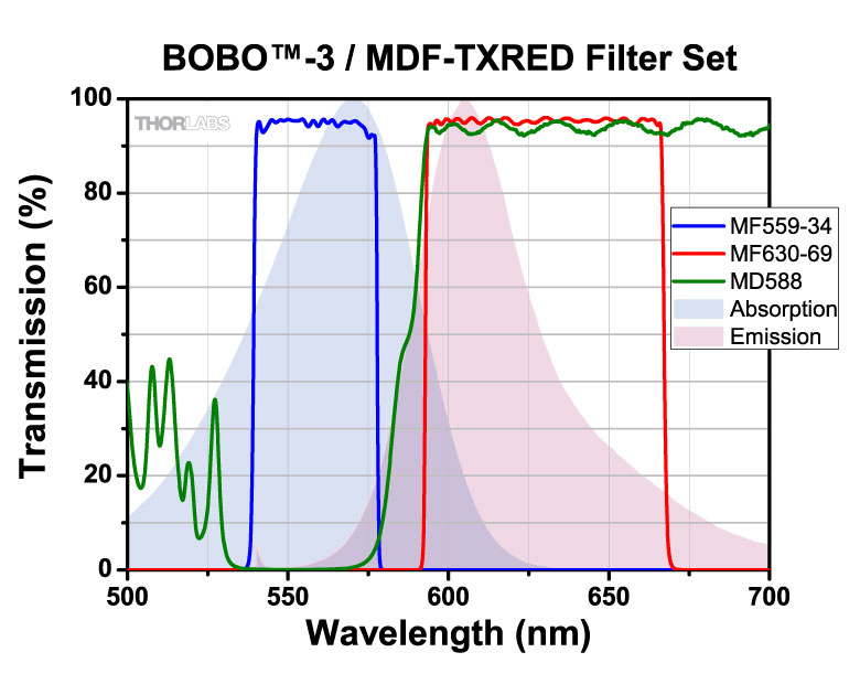
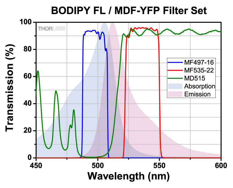
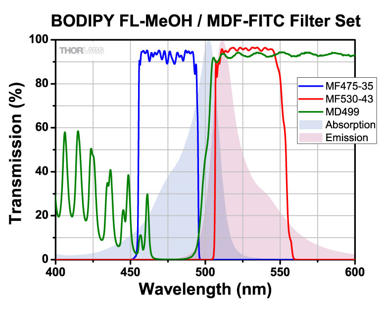
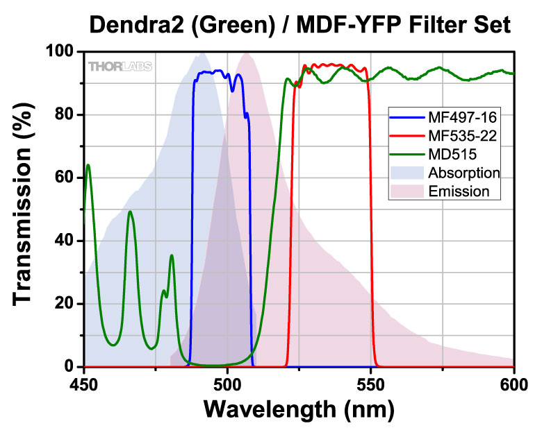
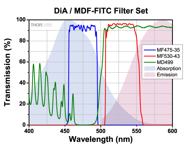
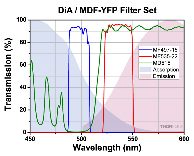
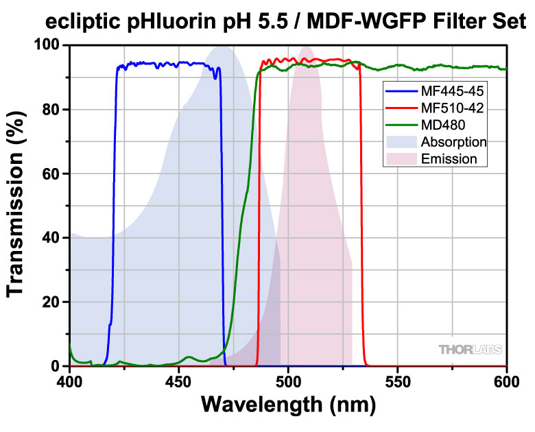
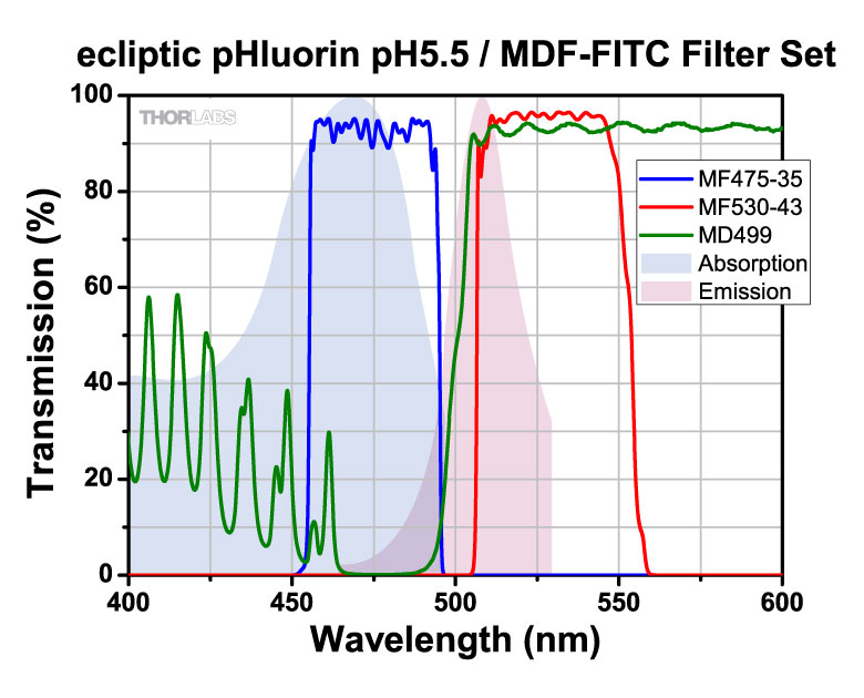
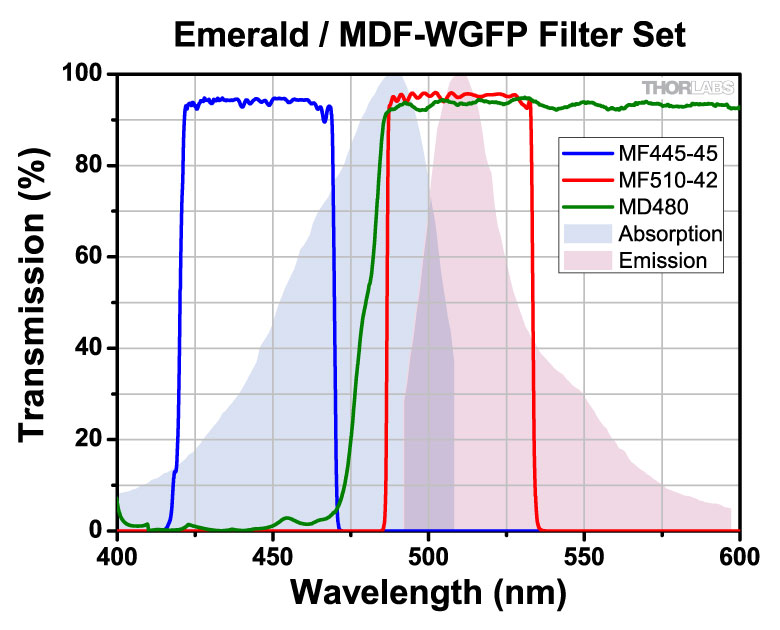
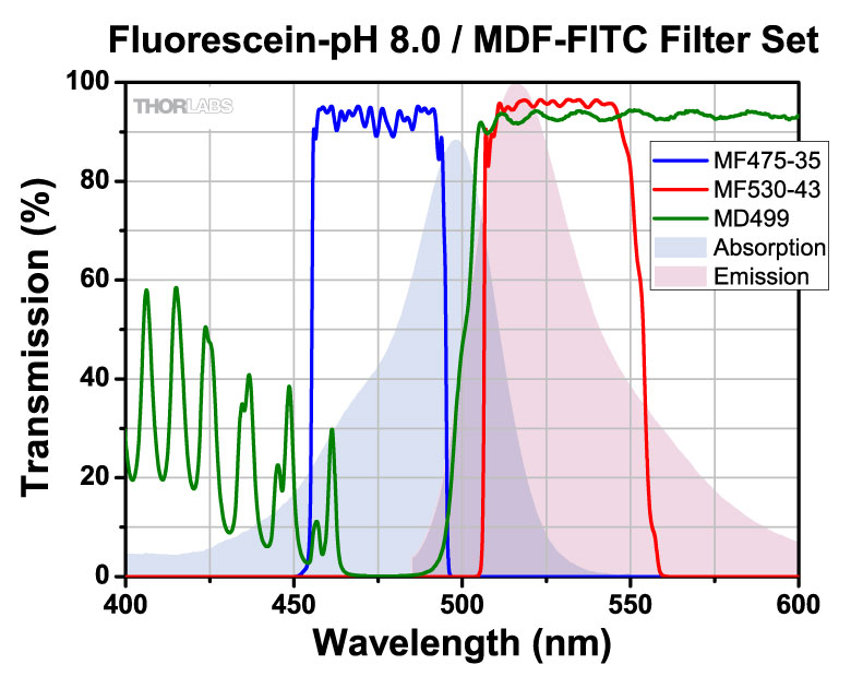
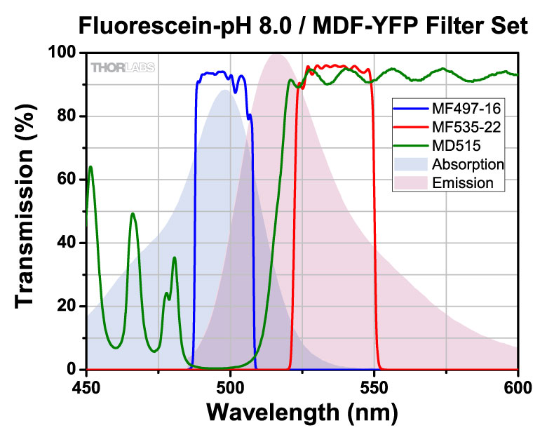
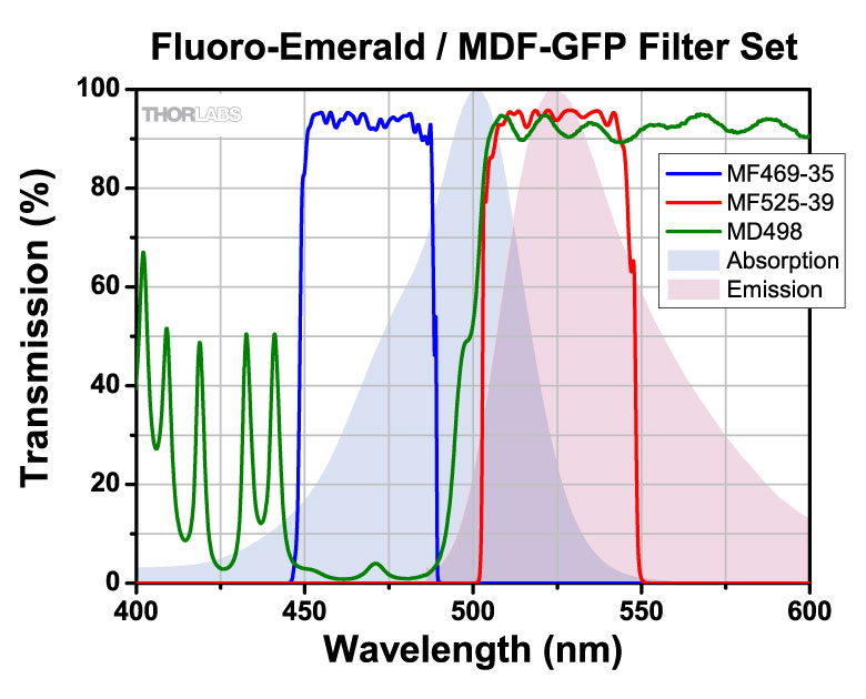
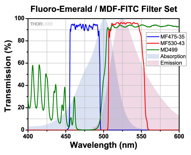
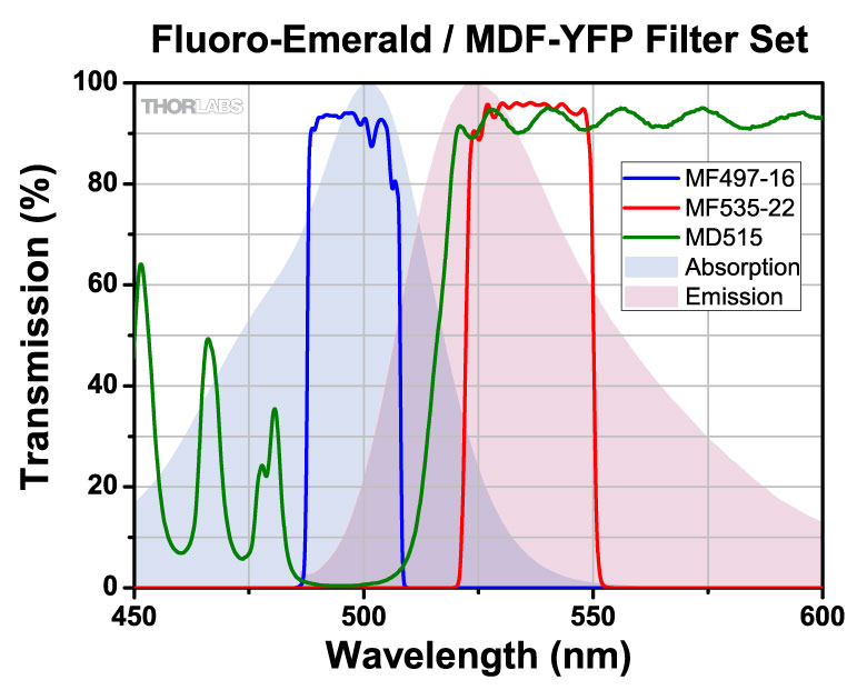
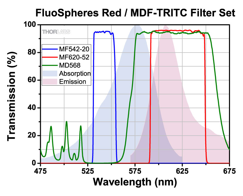
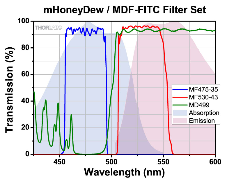
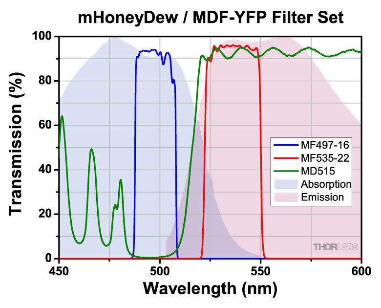
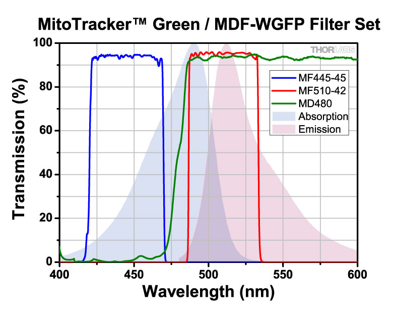
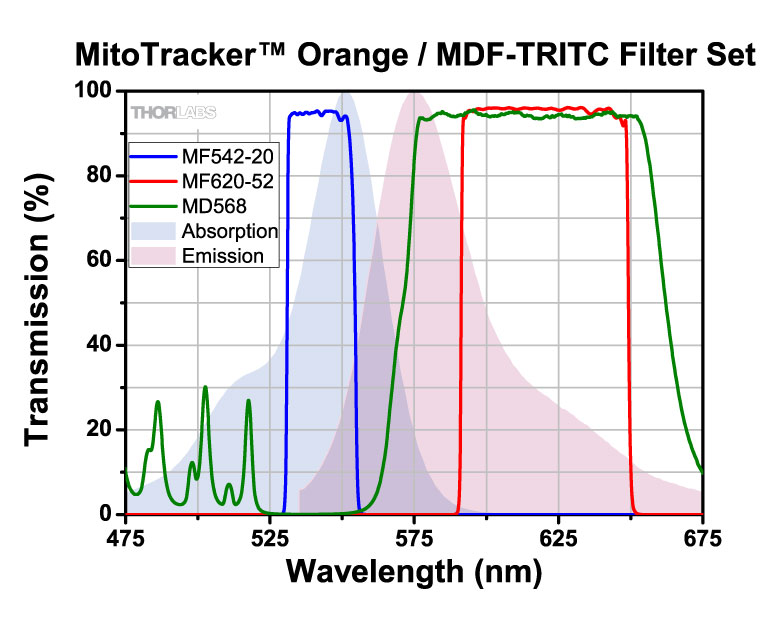
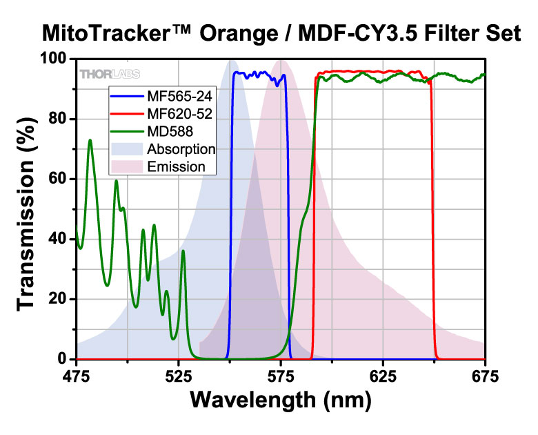
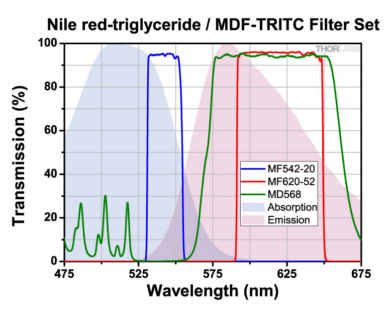
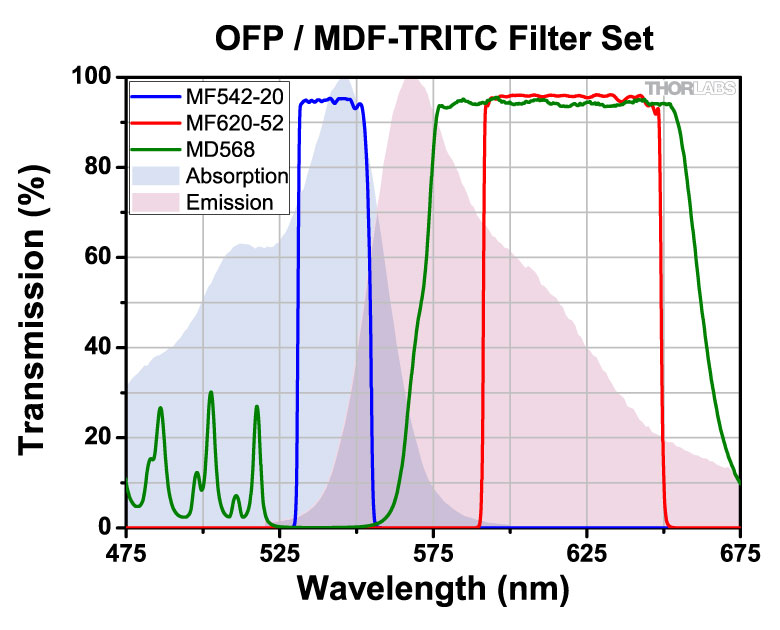
The table below displays all of the fluorophores that are compatible with our filter sets. The filter set item numbers are listed across the top row and the fluorophores are listed down the first column. Scroll through the table to view fluorophore compatibility with our filter sets.
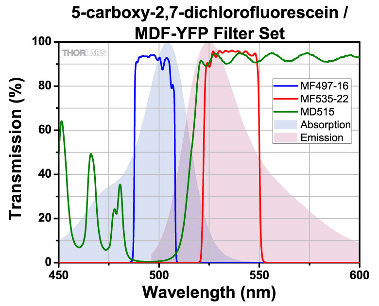
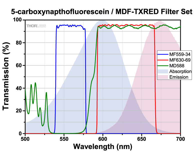
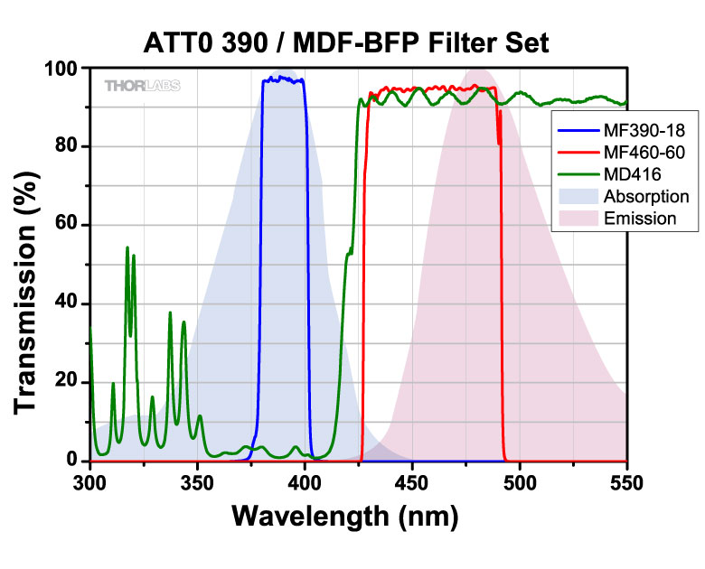
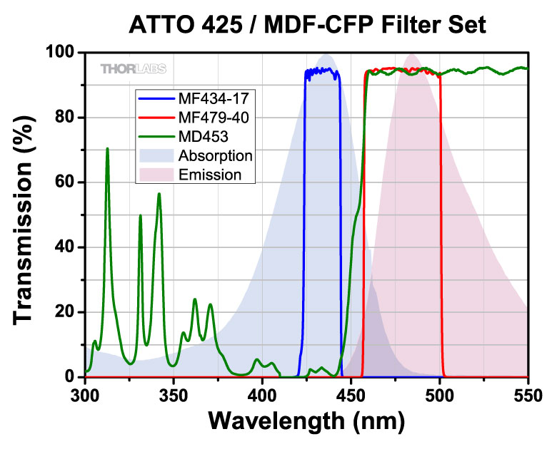
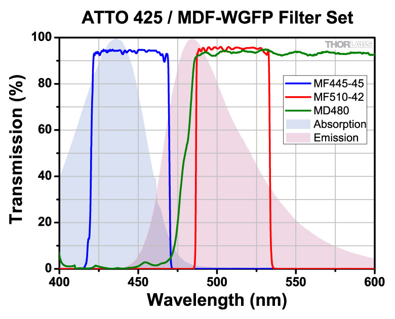
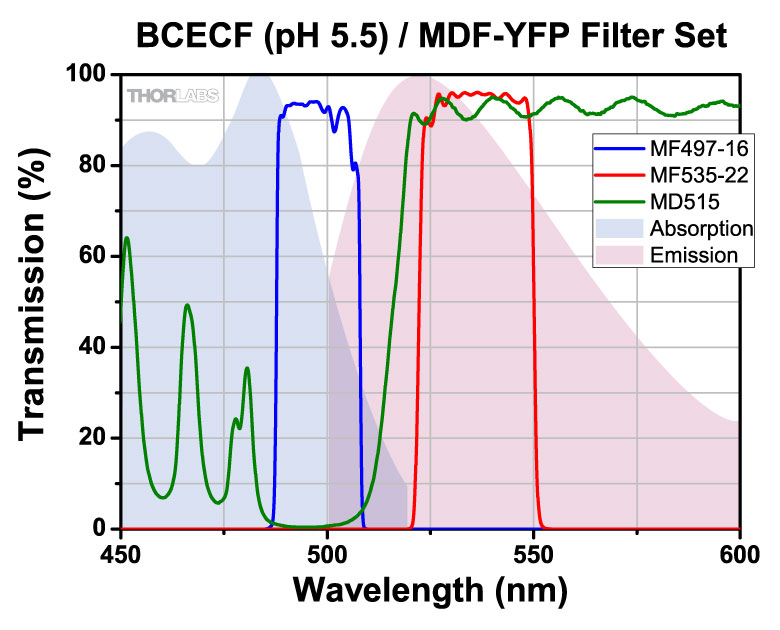
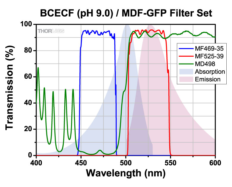
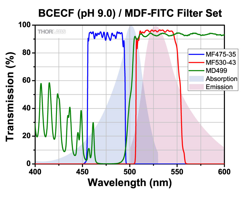
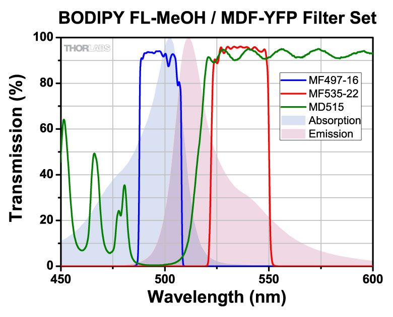
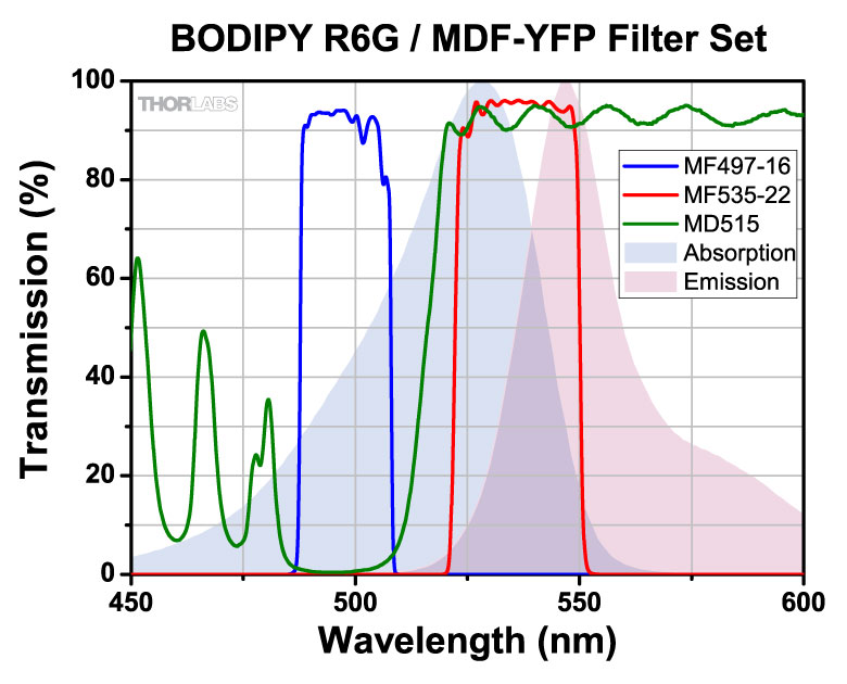
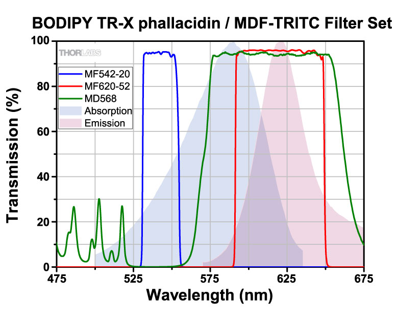
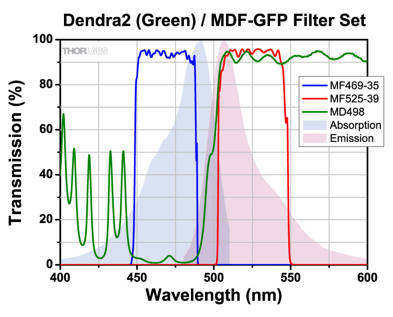
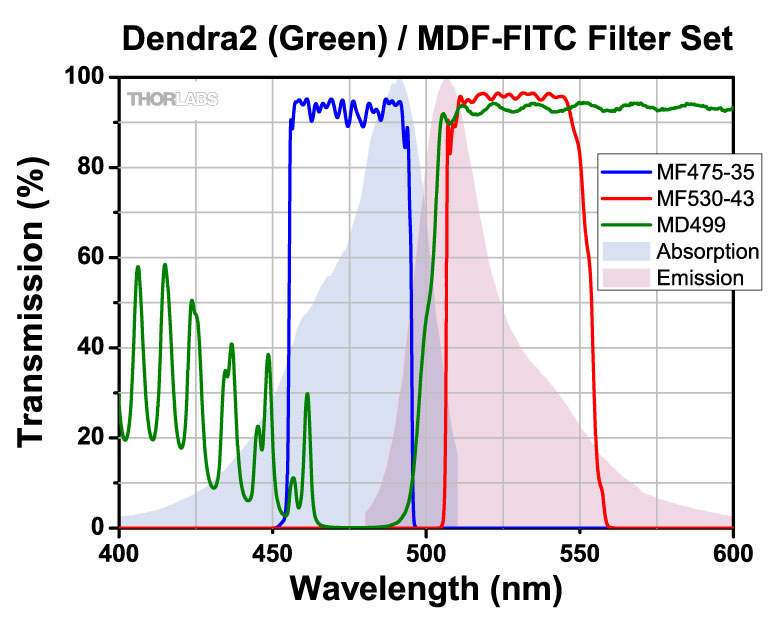
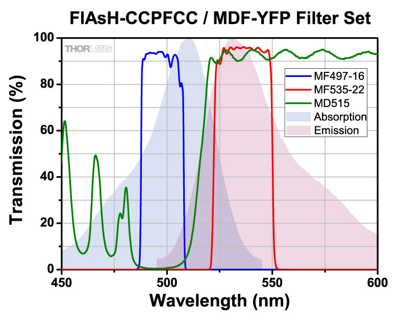
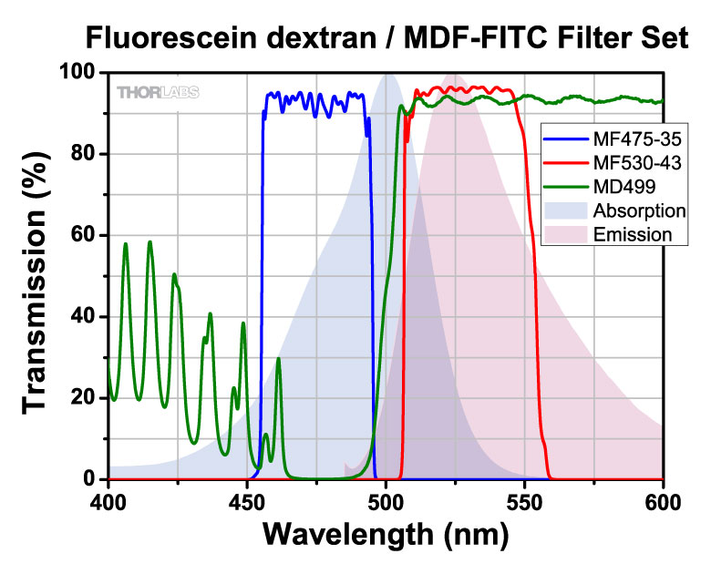
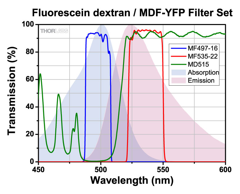
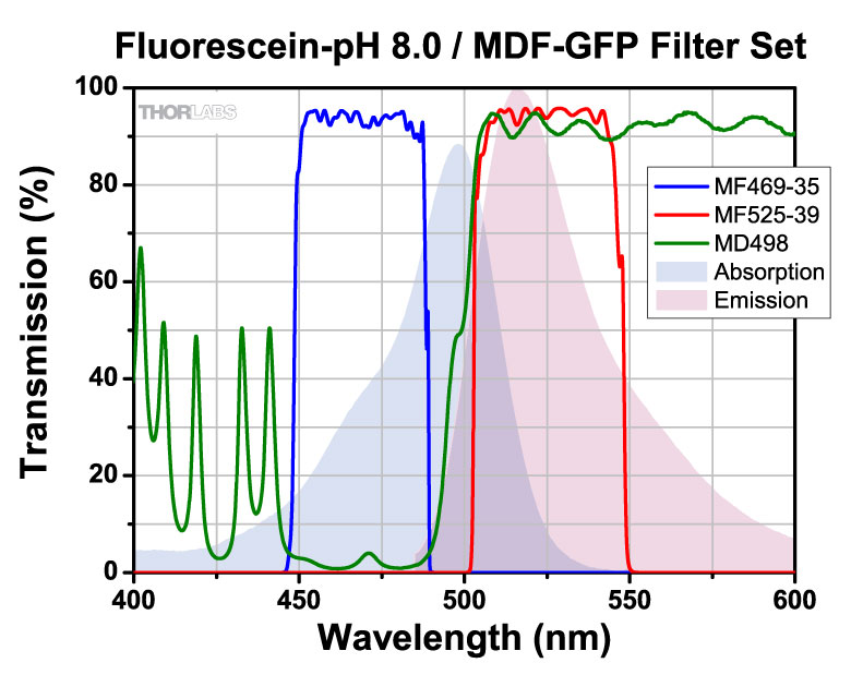
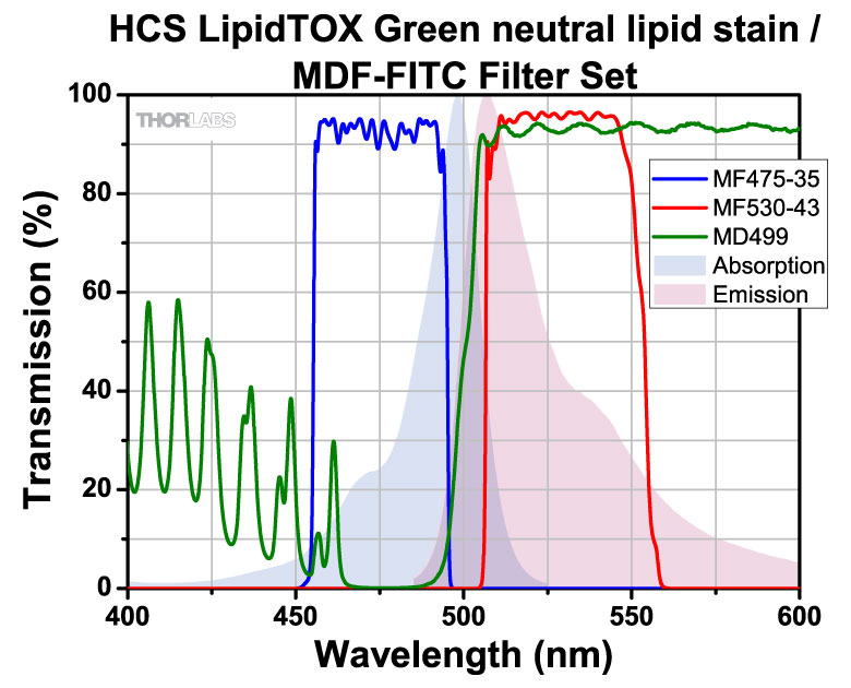
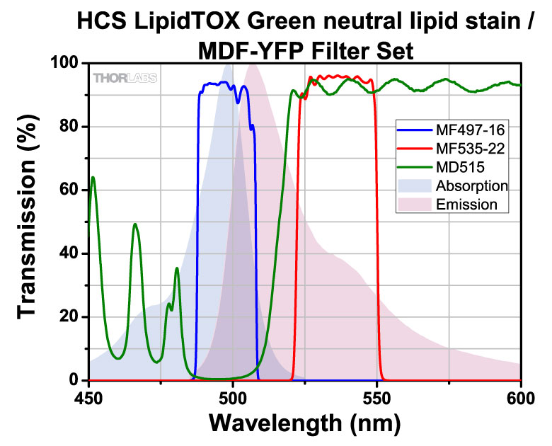
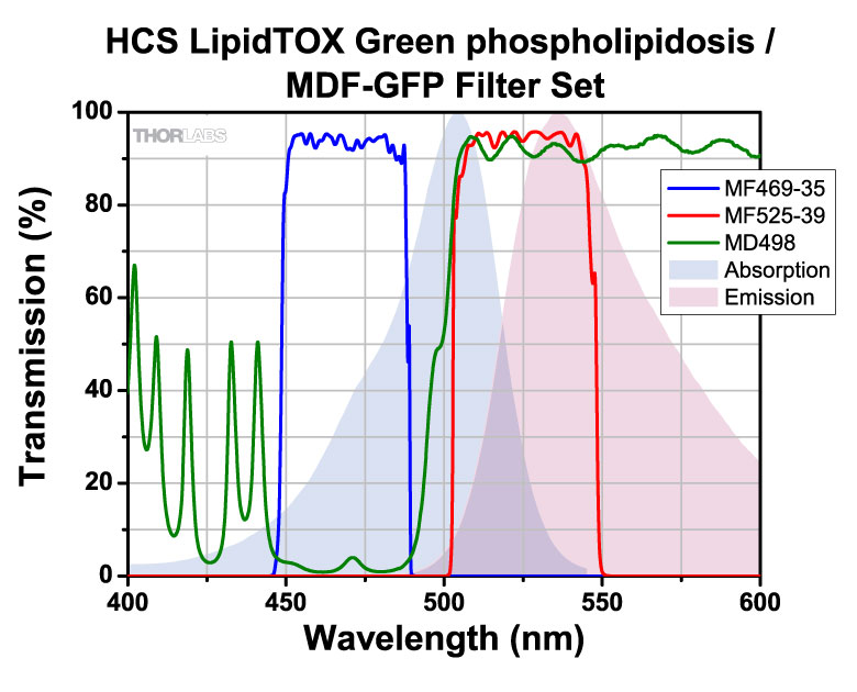
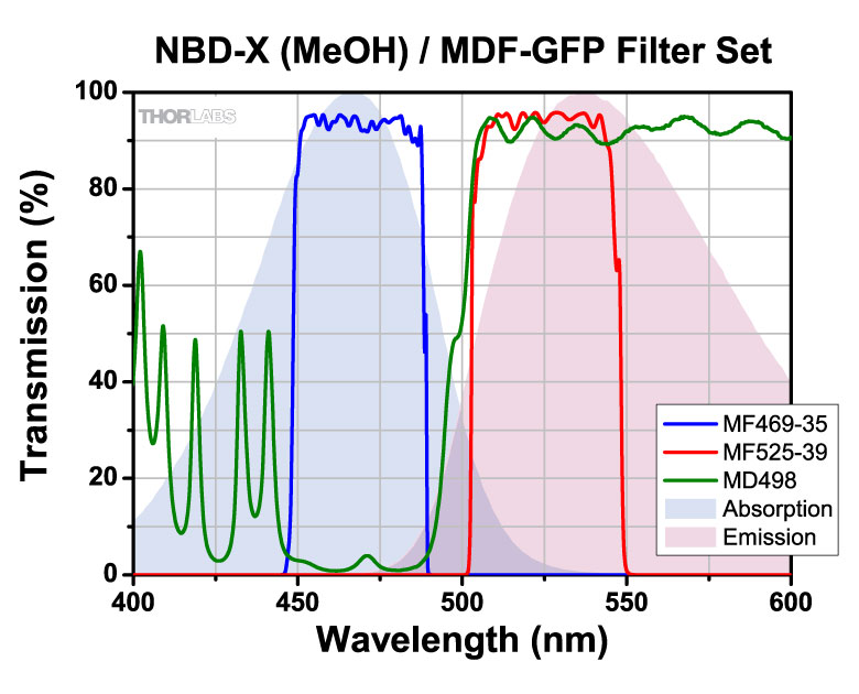
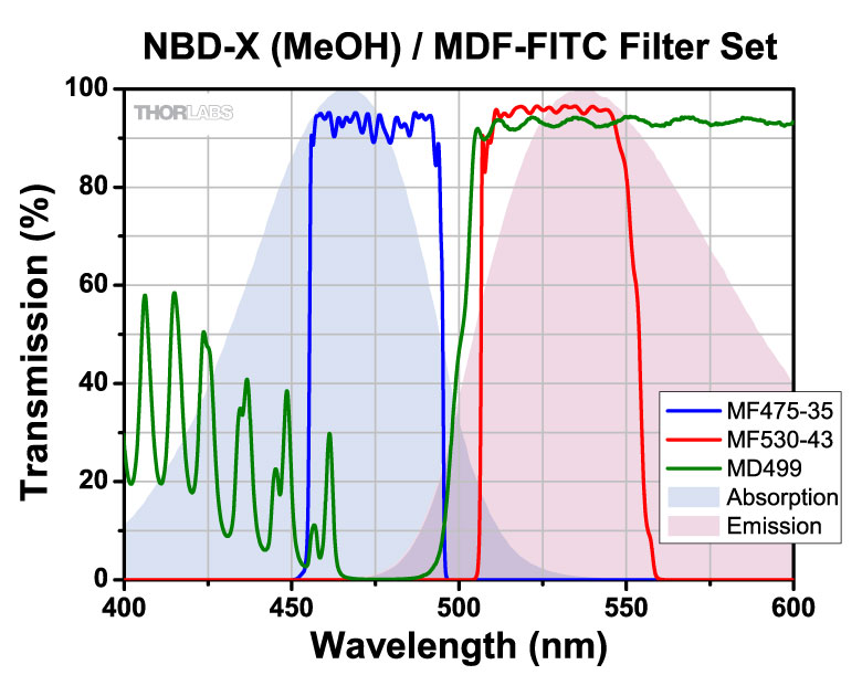
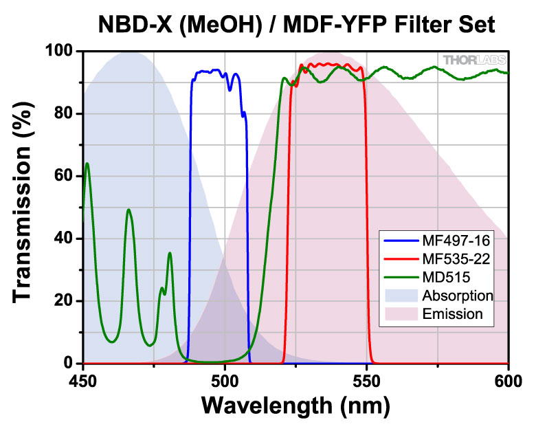
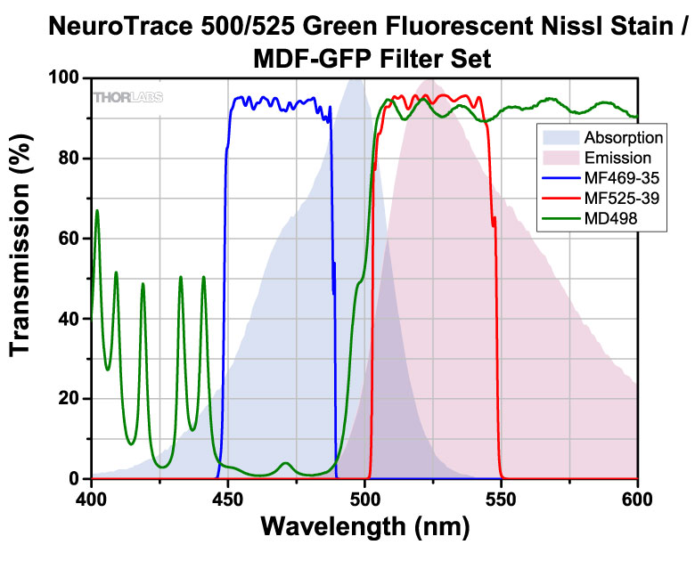
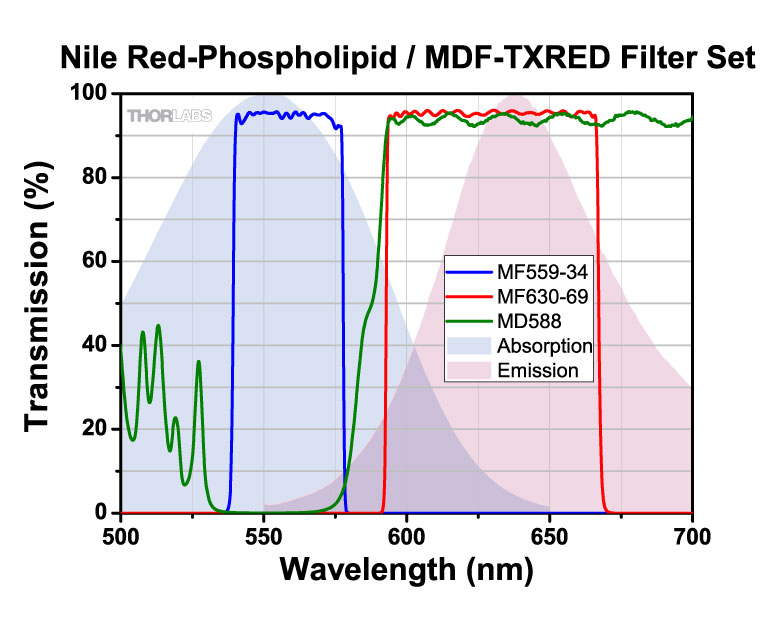
Click on the below to view the filter set transmission with the absorption and emission spectra of the fluorophore. The key to the right details the meaning of all check marks in the table below. Please note that absorption and emission spectra are unavailable if any is red.
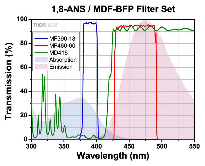
| 1,8-ANS (372 nm, 477 nm) | ✓ | ||||||||||||
| 2-dodecylresorufin-lipid (582 nm, 595 nm) | ✓ | ✓ | ✓✓ | ✓ | ✓✓ | ✓ | |||||||
| 5-carboxy-2,7-dichlorofluorescein (500 nm, 525 nm) | ✓ | ✓ | ✓✓ | ||||||||||
| 5-carboxynapthofluorescein (pH 10) (555 nm, 615 nm) | ✓ | ✓ | |||||||||||
| 5-FAM (5-carboxyfluorescein) (492 nm, 518 nm) | ✓✓ | ✓✓ | ✓ | ✓✓ | |||||||||
| 5-ROX (carboxy-X-rhodamine) (578 nm, 604 nm) | ✓ | ✓ | ✓✓✓ | ✓✓ | ✓✓ | ✓ | |||||||
| 5-TAMRA (5-carboxytetra- methylrhodamine, pH 7.0) (542 nm, 568 nm) | ✓ | ✓ | ✓ | ✓ | ✓ | ||||||||
| 6-carboxyrhodamine 6G (525 nm, 555 nm) | ✓ | ✓ | |||||||||||
| 6-JOE (520 nm, 548 nm) | ✓ | ✓ | |||||||||||
| 7-AAD (548 nm, 648 nm) | ✓ | ✓ | ✓ | ✓ | ✓ | ✓ | |||||||
| Acridine Orange (502 nm, 526 nm) | ✓ | ✓ | ✓ | ||||||||||
| Acridine Yellow (470 nm , 550 nm) | ✓ | ✓✓ | ✓ | ✓ | |||||||||
| Alexa Fluor 350™ (343 nm, 441 nm) | ✓✓ | ||||||||||||
| Alexa Fluor 405™ (401 nm, 422 nm) | ✓ | ||||||||||||
| Alexa Fluor 430™ (431 nm , 541 nm) | ✓ | ✓ | ✓ | ||||||||||
| Alexa Fluor 488™ (499 nm, 520 nm) | ✓ | ✓✓✓ | ✓✓ | ||||||||||
| Alexa Fluor 500™ (503 nm, 525 nm) | ✓ | ✓ | ✓✓ | ||||||||||
| Alexa Fluor 514™ (518 nm, 543 nm) | ✓ | ||||||||||||
| Alexa Fluor 546™ (556 nm, 572 nm) | ✓✓✓ | ✓ | |||||||||||
| Alexa Fluor 568™ (579 nm, 603 nm) | ✓ | ✓ | ✓✓✓ | ✓✓ | ✓✓ | ✓ | |||||||
| Alexa Fluor 594™ (590 nm, 618 nm) | ✓ | ✓ | ✓ | ✓ | |||||||||
| AMCA (Aminomethylcoumarin) (350 nm, 488 nm) | ✓✓ | ||||||||||||
| AmCyan1 (458 nm, 489 nm) | ✓✓✓ | ✓✓ | ✓ | ✓ | |||||||||
| Amplex UltraRed peroxidation product -pH 7.5 (568 nm, 581 nm) | ✓ | ✓ | ✓ | ✓ | ✓ | ✓ | |||||||
| Aqua 431 (430 nm,478 nm) | ✓✓ | ✓ | |||||||||||
| AsRed 2 (576 nm, 592 nm) | ✓ | ✓ | ✓ | ✓ | ✓ | ✓ | |||||||
| ATTO 390 (392 nm, 477 nm) | ✓✓ | ||||||||||||
| ATTO 425 (436 nm, 484 nm) | ✓✓ | ✓✓ | |||||||||||
| ATTO 465 (453 nm, 507 nm) | ✓ | ✓✓ | ✓✓ | ✓✓ | ✓ | ||||||||
| ATTO 488 (500 nm, 525 nm) | ✓ | ✓ | ✓ | ✓✓ | |||||||||
| ATTO 495 (495 nm, 527 nm) | ✓ | ✓ | ✓✓ | ✓ | ✓✓ | ||||||||
| ATTO 520 (516 nm, 538 nm) | ✓ | ✓ | |||||||||||
| ATTO 550 (553 nm, 576 nm) | ✓ | ✓ | ✓ | ✓ | |||||||||
| ATTO 565 (563 nm, 592 nm) | ✓ | ✓ | ✓✓ | ✓ | ✓✓ | ||||||||
| ATTO 590 (594 nm, 624 nm) | ✓ | ✓ | ✓ | ✓ | |||||||||
| ATTO 594 (601 nm, 624 nm) | ✓ | ||||||||||||
| BCECF (pH 5.5) (481 nm, 518 nm) | ✓ | ✓✓ | ✓✓ | ✓ | ✓ | ||||||||
| BCECF (pH 9.0) (502 nm, 528 nm) | ✓ | ✓ | ✓✓ | ||||||||||
| BD Horizon V450 (406 nm, 449 nm) | ✓✓ | ||||||||||||
| BD Horizon V500 (410 nm, 500 nm) | ✓ | ✓ | ✓ | ||||||||||
| BFP (EBFP) (380 nm, 440 nm) | ✓✓ | ||||||||||||
| BOBO™-1 (461 nm, 484 nm) | ✓✓✓ | ✓✓ | ✓ | ✓ | |||||||||
| BOBO™-3 (570 nm, 605 nm) | ✓ | ✓ | ✓✓ | ✓ | ✓✓ | ✓ | |||||||
| BODIPY FL (505 nm, 512 nm) | ✓ | ✓ | ✓ | ✓ | |||||||||
| BODIPY FL-MeOH (502 nm, 511 nm) | ✓ | ✓ | ✓ | ||||||||||
| BODIPY R6G (528 nm, 547 nm) | ✓ | ✓ | |||||||||||
| BODIPY TR-X phallacidin (590 nm, 621 nm) | ✓ | ✓ | ✓ | ✓ | ✓ | ||||||||
| Calcein (494 nm, 514 nm) | ✓ | ✓✓ | ✓ | ✓ | |||||||||
| Calcium Crimson (589 nm, 609 nm) | ✓ | ✓ | |||||||||||
| Calcium Green-1 (507 nm, 529 nm) | ✓ | ✓✓✓ | |||||||||||
| Calcium Orange (589 nm, 609 nm) | ✓ | ✓ | ✓ | ✓ | ✓ | ||||||||
| Carboxynaphthofluorescein (599 nm, 674 nm) | ✓ | ✓ | ✓ | ||||||||||
| Cascade Blue™ (401 nm, 419 nm) | ✓ | ||||||||||||
| CellTrace BODIPY TR methyl ester (598 nm, 625 nm) | ✓ | ✓ | ✓ | ✓ | |||||||||
| CellTrace calcein violet (400 nm, 452 nm) | ✓✓ | ||||||||||||
| CellTracker Red CMTPX (586 nm, 614 nm) | ✓ | ✓ | ✓ | ✓ | ✓ | ||||||||
| CellTracker Violet BMQC+GSH (406 nm, 526 nm) | ✓ | ✓ | |||||||||||
| Cerulean (434 nm, 473 nm) | ✓✓✓ | ✓ | ✓ | ||||||||||
| CFP (ECFP) (433 nm, 475 nm) | ✓✓✓ | ✓ | ✓ | ✓ | |||||||||
| CFP2 (490 nm, 510 nm) | ✓ | ✓✓ | ✓✓ | ✓ | ✓ | ||||||||
| Cy2™ (492 nm, 507 nm) | ✓ | ✓✓✓ | ✓ | ||||||||||
| Cy3.5™ (578 nm, 591 nm) | ✓ | ✓ | ✓✓ | ✓ | ✓✓✓ | ✓✓ | |||||||
| CyQUANT GR-DNA (502 nm, 523 nm) | ✓ | ✓ | ✓ | ✓✓ | |||||||||
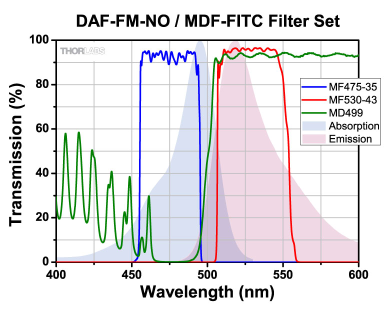
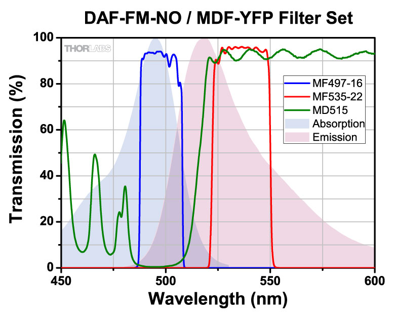
| DAF-FM-NO (495 nm, 519 nm) | ✓ | ✓✓ | ✓ | ✓✓ | |||||||||
| DAPI (359 nm, 461 nm) | ✓✓✓ | ||||||||||||
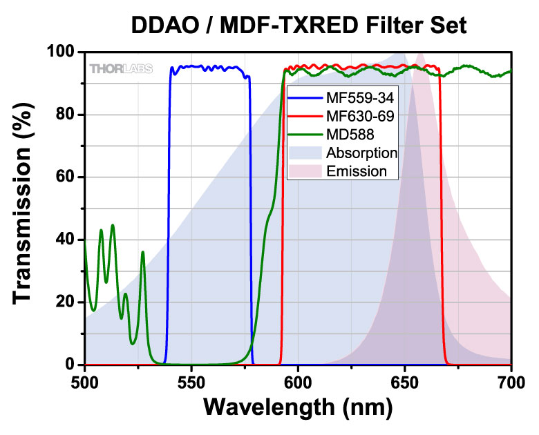
| DDAO (648 nm, 657 nm) | ✓ | ✓ | ✓ | ||||||||||
| DEAC (432 nm, 472 nm) | ✓ | ✓✓ | ✓ | ||||||||||
| Dendra2 (Green) (491 nm, 507 nm) | ✓✓ | ✓✓ | ✓ | ||||||||||
| DiA (457 nm, 586 nm) | ✓ | ✓ | ✓ | ||||||||||
| DiA (457 nm, 586 nm) | ✓ | ✓ | |||||||||||
| DiO (475 nm, 500 nm) | ✓✓✓ | ✓✓ | ✓ | ✓ | |||||||||
| Dronpa (502 nm, 516 nm) | ✓ | ✓ | ✓ | ✓ | |||||||||
| DsRed (559 nm, 583 nm) | ✓ | ✓ | ✓ | ✓ | ✓ | ||||||||
| DsRed-Express (556 nm, 584 nm) | ✓ | ✓ | ✓ | ✓ | ✓ | ||||||||
| dTomato (586 nm, 582 nm) | ✓✓✓ | ✓ | ✓ | ||||||||||
| DY-415 (418 nm, 470 nm) | ✓ | ✓ | ✓ | ||||||||||
| DY-505-Phalloidin (503 nm, 530 nm) | ✓ | ✓ | ✓✓ | ||||||||||
| DY-590 (582 nm, 599 nm) | ✓ | ✓✓ | ✓ | ✓✓ | ✓ | ||||||||
| DyLight 405 (398 nm, 420 nm) | ✓✓ | ||||||||||||
| DyLight 594 (593 nm, 618 nm) | ✓ | ✓ | ✓ | ✓ | |||||||||
| ECFP (435 nm, 475 nm) | ✓ | ✓✓ | ✓ | ||||||||||
| ecliptic pHluorin pH 5.5 (473 nm, 507 nm) | ✓✓ | ✓✓ | ✓✓ | ✓ | |||||||||
| Emerald (491 nm, 511 nm) | ✓ | ✓✓ | ✓✓ | ✓ | ✓ | ||||||||
| Eosin (525 nm, 546 nm) | ✓✓✓ | ✓✓ | |||||||||||
| ER-Tracker™ Blue-White DPX (372 nm, 557 nm) | ✓ | ||||||||||||
| Ethidium bromide (518 nm, 603 nm) | ✓ | ✓ | ✓ | ✓ | |||||||||
| Ethidium homodimer (527 nm, 617 nm) | ✓ | ✓✓ | ✓ | ✓ | ✓ | ✓ | |||||||
| evoglow-Bs1 (449 nm, 496 nm) | ✓ | ✓✓ | ✓ | ||||||||||
| FITC (Fluorescein) (495 nm, 519 nm) | ✓ | ✓✓✓ | ✓✓ | ✓✓ | |||||||||
| FlAsH-CCPFCC (511 nm, 530 nm) | ✓ | ✓✓ | ✓ | ||||||||||
| Fluo-3 (506 nm, 527 nm) | ✓ | ✓✓✓ | |||||||||||
| Fluo-4 (494 nm, 516 nm) | ✓ | ✓✓✓ | ✓✓ | ||||||||||
| Fluorescein dextran (501 nm, 524 nm) | ✓ | ✓ | ✓ | ✓✓ | |||||||||
| Fluorescein-pH 8.0 (489 nm, 517 nm) | ✓ | ✓✓ | ✓ | ✓ | |||||||||
| Fluoro-Emerald (494 nm, 518 nm) | ✓ | ✓ | ✓ | ✓✓ | |||||||||
| FluoSpheres Crimson fluorescent microspheres (620 nm, 646 nm) | ✓ | ✓ | ✓ | ||||||||||
| FluoSpheres Red fluorescent microspheres 656 nm, 683 nm) | ✓ | ✓✓ | ✓✓ | ||||||||||
| FluoSpheres Yellow-Green fluorescent microspheres (503 nm, 514 nm) | ✓ | ✓ | ✓ | ✓ | |||||||||
| FM 1-43 (473 nm, 579 nm) | ✓ | ✓ | ✓ | ✓ | ✓ | ||||||||
| GFP (EGFP) (489 nm, 511 nm) | ✓ | ✓✓ | ✓✓ | ✓ | ✓ | ||||||||
| Green 496 (496 nm, 520 nm) | ✓ | ✓✓ | ✓ | ✓✓ | |||||||||
| Green 500 (501 nm, 524 nm) | ✓ | ✓ | ✓ | ✓✓ | |||||||||
| HcRed1 (588 nm, 618 nm) | ✓ | ✓ | ✓ | ✓ | ✓ | ||||||||
| HCS LipidTOX Green neutral lipid stain (498 nm, 507 nm) | ✓✓ | ✓ | ✓ | ||||||||||
| HCS LipidTOX Green phospholipidosis (504 nm, 536 nm) | ✓ | ✓ | ✓✓ | ||||||||||
| HCS LipidTOX Red neutral lipid stain (582 nm, 616 nm) | ✓ | ✓ | ✓✓ | ✓ | ✓✓ | ✓ | |||||||
| HCS LipidTOX Red phospholipidosis (584 nm, 608 nm) | ✓ | ✓ | ✓ | ✓ | ✓ | ||||||||
| HiLyte Fluor™ 405 (403 nm, 428 nm) | ✓✓ | ||||||||||||
| HiLyte Fluor™ 488 (497 nm, 526 nm) | ✓ | ✓✓ | ✓ | ✓✓ | |||||||||
| HiLyte Fluor™ 594 (592 nm, 616 nm) | ✓ | ✓ | ✓ | ✓ | |||||||||
| Hoechst 33258 (532 nm, 455 nm) | ✓✓ | ✓ | |||||||||||
| Hoechst 33342 (352 nm, 455 nm) | ✓✓ | ||||||||||||
| Hoechst 34580 (392 nm, 440 nm) | ✓✓ | ||||||||||||
| Hypericin (600 nm, 603 nm) | ✓ | ||||||||||||
| KFP-Red (575 nm, 599 nm) | ✓ | ✓ | ✓✓ | ✓ | ✓✓ | ✓ | |||||||
| LIVE-DEAD Fixable Green Dead Cell Stain (498 nm, 525 nm) | ✓ | ✓✓ | ✓ | ✓✓ | |||||||||
| LIVE-DEAD Fixable Red Dead Cell Stain (595 nm, 613 nm) | ✓ | ✓ | ✓ | ✓ | ✓ | ||||||||
| Live-Dead Fixable Violet Dead Cell Stain (403 nm, 455 nm) | ✓✓ | ||||||||||||
| LOLO-1 (568 nm, 580 nm) | ✓ | ✓ | ✓ | ✓ | ✓ | ||||||||
| Lucifer yellow (428 nm, 544 nm) | ✓ | ✓ | |||||||||||
| LysoSensor Blue (374 nm, 424 nm) | ✓✓ | ||||||||||||
| LysoSensor Green (448 nm, 502 nm) | ✓ | ✓✓ | ✓✓ | ✓ | |||||||||
| LysoTracker Green (501 nm, 509 nm) | ✓ | ✓ | ✓ | ✓ | |||||||||
| LysoTracker Red (573 nm, 592 nm) | ✓ | ✓ | ✓✓ | ✓✓ | |||||||||
| LysoTracker Yellow HCK-123 (488 nm, 565 nm) | ✓ | ✓ | ✓ | ✓ | |||||||||
| Magnesium Green (507 nm, 531 nm) | ✓ | ✓✓ | ✓ | ||||||||||
| Magnesium Orange (587 nm, 610 nm) | ✓ | ✓ | ✓ | ✓ | ✓ | ||||||||
| mApple (566 nm, 594 nm) | ✓ | ✓ | ✓✓ | ✓ | ✓✓ | ||||||||
| Marina Blue (363 nm, 461 nm) | ✓ | ||||||||||||
| mBBr+GSH (394 nm, 490 nm) | ✓✓ | ✓ | ✓ | ||||||||||
| mCherry (587 nm, 610 nm) | ✓ | ✓✓✓ | ✓✓✓ | ✓ | ✓✓✓ | ||||||||
| Mecrocyanine 540 (559 nm, 579 nm) | ✓ | ✓ | ✓ | ||||||||||
| mHoneyDew (478 nm, 562 nm) | ✓ | ✓ | ✓ | ✓✓ | ✓ | ||||||||
| MitoTracker™ Green (490 nm, 512 nm) | ✓ | ✓✓ | ✓✓ | ✓ | ✓ | ||||||||
| MitoTracker™ Orange (551 nm, 575 nm) | ✓ | ✓ | ✓ | ✓ | |||||||||
| MitoTracker™ Red (578 nm, 598 nm) | ✓ | ✓✓ | ✓ | ✓✓ | ✓ | ||||||||
| mKate2 (588 nm, 633 nm) | ✓ | ✓ | ✓ | ✓ | ✓ | ||||||||
| mPlum (589 nm,649 nm) | ✓ | ✓ | ✓ | ✓ | |||||||||
| mRFP (555 nm, 583 nm) | ✓ | ✓ | ✓ | ✓ | ✓ | ||||||||
| mRFP1 (584 nm, 700 nm) | ✓ | ✓✓✓ | ✓✓ | ✓ | |||||||||
| mRuby (558 nm, 605 nm) | ✓ | ✓✓ | ✓✓ | ✓ | ✓✓ | ✓ | |||||||
| mStrawberry (574 nm, 596 nm) | ✓ | ✓ | ✓✓ | ✓ | ✓✓✓ | ||||||||
| mTangerine (568 nm, 585 nm) | ✓ | ✓ | ✓ | ✓ | ✓ | ✓ | |||||||
| mTFP1 (462 nm, 492 nm) | ✓ | ✓✓ | ✓ | ✓ | |||||||||
| mWasabi (493 nm, 509 nm) | ✓ | ✓✓ | ✓ | ||||||||||
| NBD-X (MeOH) (467 nm, 538 nm) | ✓ | ✓✓ | ✓✓ | ✓ | |||||||||
| NeuroTrace 500/525 Green Fluorescence Nissl Stain (495 nm, 524 nm) | ✓ | ✓✓ | ✓ | ✓✓ | |||||||||
| Nile red-phospholipid (553 nm, 637 nm) | ✓✓ | ✓✓ | ✓ | ✓✓ | ✓ | ||||||||
| Nile red-triglyceride (510 nm, 583 nm) | ✓ | ✓ | |||||||||||
| OFP (547 nm, 567 nm) | ✓ | ✓ | ✓ | ✓ | |||||||||
| Orange 552 (552 nm, 574 nm) | ✓ | ✓ | ✓ | ✓ | |||||||||
| Oregon Green™ 488 (488 nm, 526 nm) | ✓ | ✓✓ | ✓ | ✓✓ | |||||||||
| Oregon Green™ 514 (513 nm, 532 nm) | ✓ | ||||||||||||
| Pacific Blue™ (404 nm, 455 nm) | ✓✓ | ||||||||||||
| PerCP (490 nm, 677 nm) | ✓ | ✓ | ✓ | ✓ | |||||||||
| pHrodo™, succinimidyl ester (560 nm, 587 nm) | ✓ | ✓ | ✓ | ✓ | ✓ | ||||||||
| PicoGreen (502 nm, 522 nm) | ✓ | ✓ | ✓ | ✓✓ | |||||||||
| PKH67 (488 nm, 500 nm) | ✓ | ✓✓ | ✓ | ✓ | |||||||||
| POPO-1 (433 nm, 457 nm) | ✓✓ | ✓ | |||||||||||
| PO-PRO-1 (433 nm, 456 nm) | ✓✓ | ||||||||||||
| Propidium Iodide (PI) (305 nm, 617 nm) | ✓✓ | ✓✓ | ✓ | ✓ | ✓ | ||||||||
| Pro-Q Diamond (556 nm, 583 nm) | ✓ | ✓ | ✓ | ✓ | ✓ | ||||||||
| Qdot® 525 Nanocrystals (300 nm, 525 nm) | ✓ | ✓ | ✓ | ✓ | ✓ | ||||||||
| Qdot® 545 Nanocrystals (300 nm, 543 nm) | ✓ | ||||||||||||
| Qdot® 585 Nanocrystals (300 nm, 588 nm) | ✓ | ✓ | ✓✓ | ||||||||||
| Qdot® 605 Nanocrystals (300 nm, 602 nm) | ✓ | ✓ | ✓ | ✓ | |||||||||
| Qdot® 625 Nanocrystals (300 nm, 621 nm) | ✓ | ✓ | ✓ | ✓ | |||||||||
| Qdot® 655 Nanocrystals (300 nm, 654 nm) | ✓ | ✓ | ✓ | ||||||||||
| ratiometric pHluorin pH5 (500 nm, 509 nm) | ✓ | ✓ | |||||||||||
| ReAsH-CCPGCC (592 nm, 606 nm) | ✓ | ✓ | ✓ | ✓ | ✓ | ✓ | |||||||
| Red 580 (580 nm, 603 nm) | ✓ | ✓ | ✓✓ | ✓ | ✓✓ | ✓ | |||||||
| Resorufin (571 nm, 584 nm) | ✓ | ✓ | ✓ | ✓ | ✓ | ||||||||
| Rhod-2 (553 nm, 577 nm) | ✓ | ✓ | ✓ | ✓ | |||||||||
| Rhodamine 110 (497 nm, 519 nm) | ✓ | ✓✓ | ✓ | ✓✓ | |||||||||
| Rhodamine 123 (507 nm, 529 nm) | ✓ | ✓✓✓ | |||||||||||
| Rhodamine Green (497 nm, 523 nm) | ✓ | ✓ | ✓✓ | ||||||||||
| Rhodamine phalloidin (558 nm, 575 nm) | ✓ | ✓ | ✓ | ✓ | ✓ | ||||||||
| Rhodamine Red-X (573 nm, 951 nm) | ✓ | ✓✓ | ✓✓ | ✓ | |||||||||
| Rhodol Green (497 nm, 524 nm) | ✓ | ✓✓ | ✓ | ✓✓ | |||||||||
| rsGFP (red shifted GFP, S65T) (498 nm, 516 nm) | ✓✓ | ||||||||||||
| sgBFP™ (387 nm, 451 nm) | ✓✓ | ||||||||||||
| sgGFP™ (super glow GFP) (472 nm, 506 nm) | ✓✓ | ✓✓ | ✓✓ | ✓ | |||||||||
| Sirius (355 nm, 424 nm) | ✓ | ||||||||||||
| SNARF (carboxy) 514 Excitation pH 9 (576 nm, 638 nm) | ✓ | ✓✓ | ✓✓ | ||||||||||
| SNARF-1 488 nm (pH 6.0 ) (548 nm, 586 nm) | ✓ | ✓ | ✓ | ✓ | ✓ | ||||||||
| SNARF-1 488 nm (pH 9.0) (576 nm, 638 nm) | ✓ | ✓✓ | ✓ | ✓✓ | ✓ | ||||||||
| SNARF-1 514 nm (pH 6.0 ) (549 nm, 587 nm) | ✓ | ✓✓ | ✓ | ✓ | ✓✓ | ||||||||
| SNARF-1 514 nm (pH 9.0) (576 nm, 638 nm) | ✓ | ✓✓ | ✓ | ✓✓ | ✓ | ||||||||
| Sodium Green (507 nm, 532 nm) | ✓ | ✓ | ✓ | ✓✓ | |||||||||
| SpectrumAqua (434 nm, 481 nm) | ✓✓ | ✓ | |||||||||||
| SpectrumBlue (405 nm, 449 nm) | ✓✓ | ||||||||||||
| SpectrumGreen (497 nm, 538 nm) | ✓ | ✓✓ | |||||||||||
| SpectrumOrange (554 nm, 587 nm) | ✓ | ✓ | ✓ | ✓ | ✓ | ||||||||
| SpectrumRed (587 nm, 615 nm) | ✓ | ✓ | ✓ | ||||||||||
| Sulforhodamine 101-EtOH (578 nm, 593 nm) | ✓ | ✓✓ | ✓ | ✓✓ | ✓ | ||||||||
| SYBR Gold nucleic acid gel stain-DNA (469 nm, 539 nm) | ✓ | ✓✓ | ✓✓ | ||||||||||
| SYBR Green I nucleic acid gel stain-DNA (498 nm, 522 nm) | ✓ | ✓✓ | ✓ | ✓✓ | |||||||||
| SYBR Safe DNA gel stain-DNA (509 nm, 526 nm) | ✓ | ✓ | ✓✓ | ||||||||||
| SYTO 9 (483 nm, 500 nm) | ✓ | ✓✓ | ✓ | ✓✓ | |||||||||
| SYTO 11 (506 nm, 525 nm) | ✓ | ✓ | ✓✓ | ||||||||||
| SYTO 13 (448 nm, 506 nm) | ✓✓ | ✓✓ | ✓ | ✓ | |||||||||
| SYTO 16 (489 nm, 520 nm) | ✓✓ | ✓✓ | ✓ | ✓✓ | |||||||||
| SYTO 45 (451 nm, 485 nm) | ✓ | ✓✓ | ✓ | ✓ | |||||||||
| SYTO RNASelect green fluorescent cell stain (503 nm, 527 nm) | ✓ | ✓ | ✓ | ✓✓ | |||||||||
| SYTOX Blue (444 nm, 470 nm) | ✓✓✓ | ✓ | |||||||||||
| SYTOX Green-DNA (504 nm, 524 nm) | ✓ | ✓ | ✓ | ✓✓ | |||||||||
| TagBFP (402 nm, 457 nm) | ✓✓ | ||||||||||||
| TagCFP (458 nm, 480 nm) | ✓✓ | ✓ | ✓ | ✓ | |||||||||
| tdTomato (556 nm, 582 nm) | ✓✓✓ | ||||||||||||
| Tetramethylrhodamine dextran (554 nm, 582 nm) | ✓ | ✓ | ✓ | ✓ | ✓ | ||||||||
| Texas Red dextran (592 nm, 613 nm) | ✓ | ✓ | ✓ | ✓ | ✓ | ||||||||
| Texas Red DHPE (584 nm, 608 nm) | ✓ | ✓ | ✓ | ✓ | ✓ | ✓ | |||||||
| Texas Red® (592 nm, 614 nm) | ✓✓✓ | ✓✓ | ✓ | ✓ | |||||||||
| ThiolTracker Violet GSH (404 nm, 526 nm) | ✓ | ✓ | |||||||||||
| TO-PRO-1 (515 nm, 531 nm) | ✓ | ✓ | ✓ | ||||||||||
| TOTO-1 (514 nm, 531 nm) | ✓ | ✓ | ✓ | ✓ | ✓ | ||||||||
| TRITC (Tertamethylrhodamine) (552 nm, 578 nm) | ✓ | ✓ | ✓ | ✓ | |||||||||
| TRITC (Tertamethylrhodamine) - "reddish" (552 nm, 578 nm) | ✓✓ | ||||||||||||
| TurboFP635 (Katushka) (591 nm, 638 nm) | ✓ | ✓ | ✓ | ✓ | |||||||||
| TurboGFP (482 nm, 503 nm) | ✓ | ✓✓ | ✓✓ | ✓ | |||||||||
| TurboRFP (553 nm, 573 nm) | ✓ | ✓ | ✓ | ✓ | ✓ | ||||||||
| TurboYFP (525 nm, 538 nm) | ✓ | ✓ | |||||||||||
| Venus (516 nm, 528 nm) | ✓ | ✓ | ✓ | ||||||||||
| Vybrant DyeCycle Green (506 nm, 534 nm) | ✓ | ✓ | ✓ | ✓✓ | |||||||||
| Vybrant DyeCycle Orange (519 nm, 563 nm) | ✓ | ✓ | |||||||||||
| Vybrant DyeCycle Violet (369 nm, 437 nm) | ✓ | ||||||||||||
| wtGFP (wild type GFP, non-UV excitation) (474 nm, 509 nm) | ✓✓✓ | ✓✓ | ✓✓ | ✓ | |||||||||
| X-Rhod-1 Indicator (580 nm, 601 nm) | ✓ | ✓ | ✓✓ | ✓✓ | ✓✓ | ✓✓ | |||||||
| YFP (yellow GFP) (513 nm, 530 nm) | ✓ | ✓✓✓ | ✓✓ | ||||||||||
| YO-PRO-1 (491 nm, 506 nm) | ✓ | ✓✓ | ✓✓ | ✓ | ✓ | ||||||||
| YOYO-1 (491 nm, 508 nm) | ✓ | ✓✓ | ✓✓ | ✓ | ✓ | ||||||||
| YOYO-3 (611 nm, 631 nm) | ✓ | ✓ | ✓ | ✓ |
.jpg)
.jpg)
.gif)
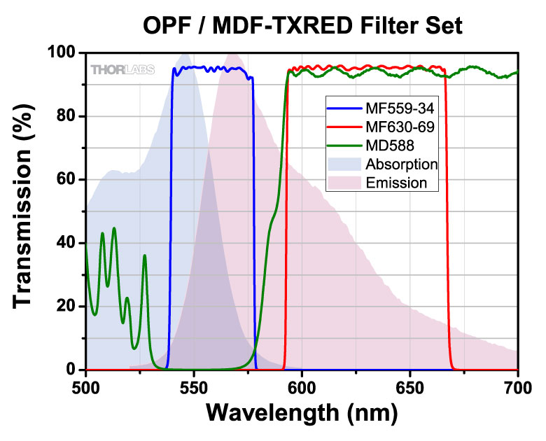
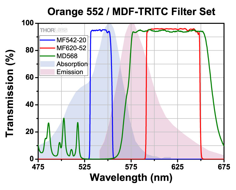
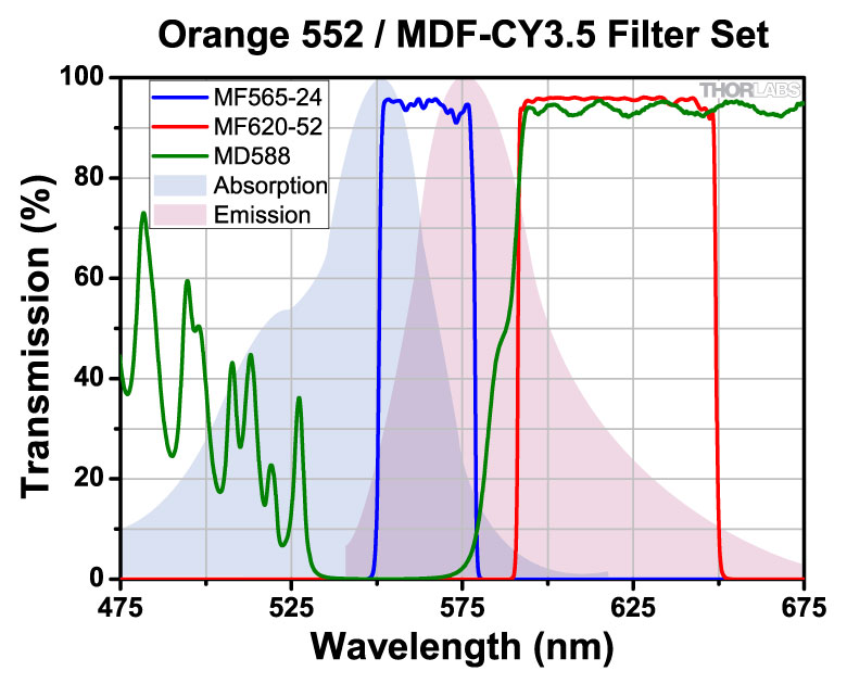
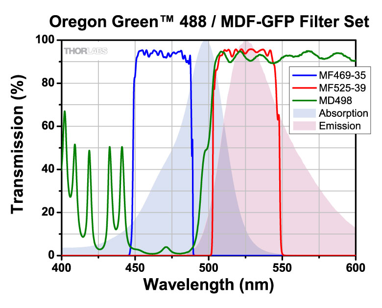
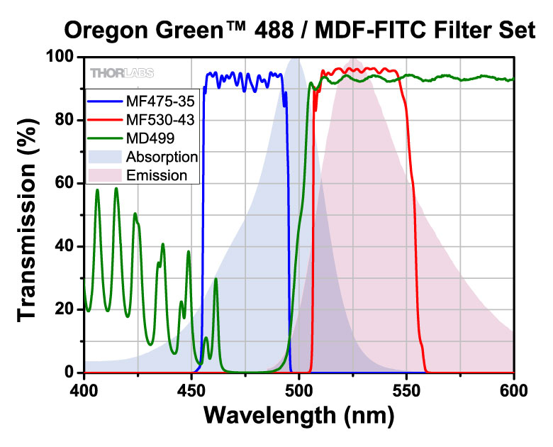
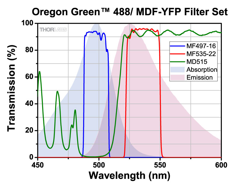
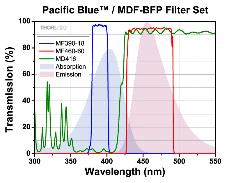
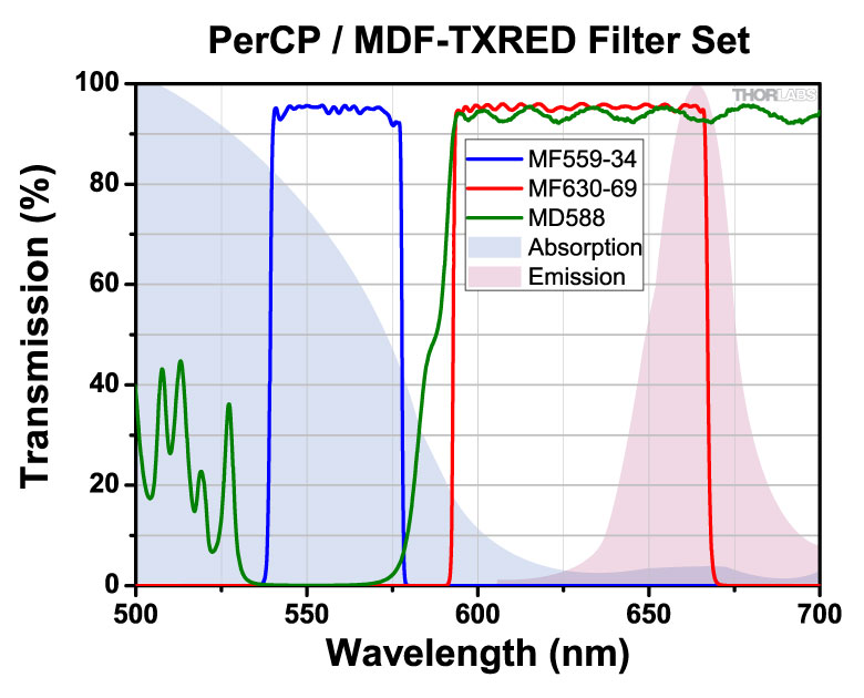
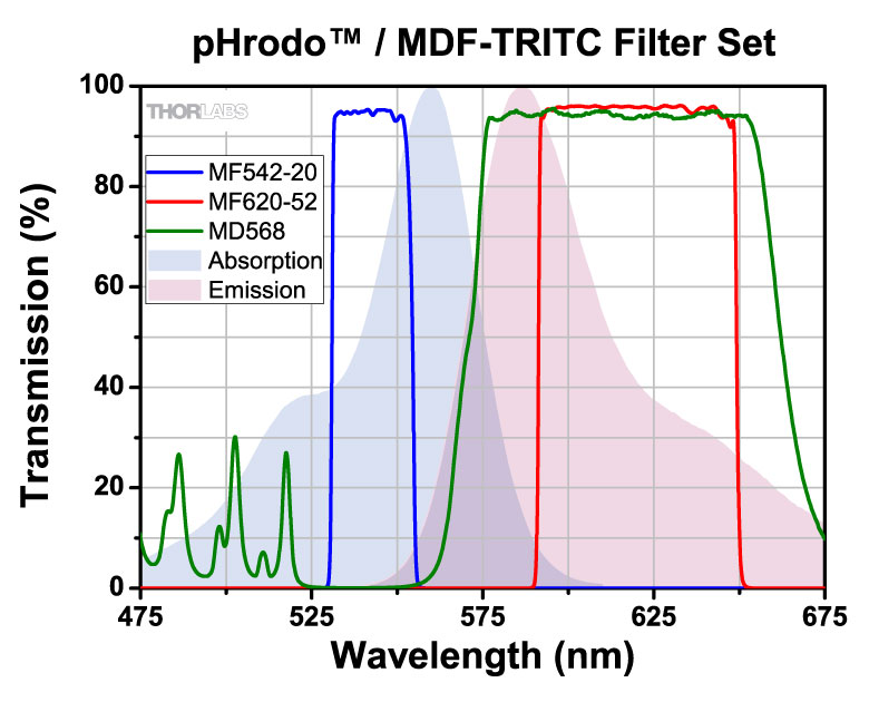
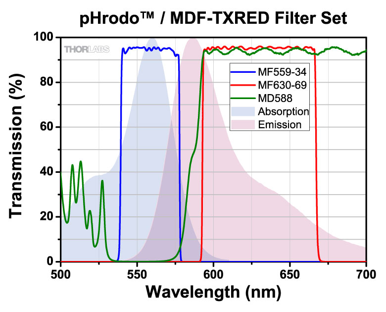
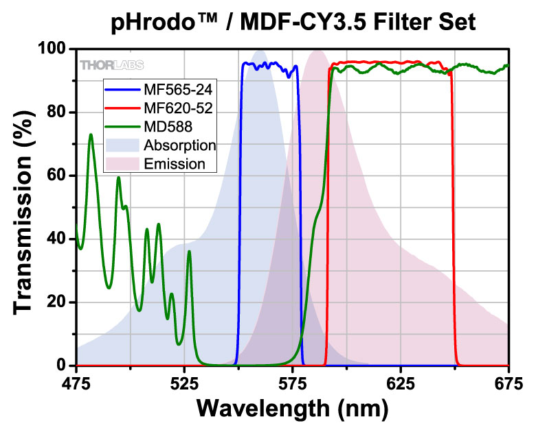
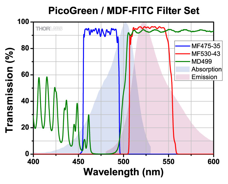
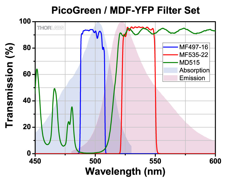
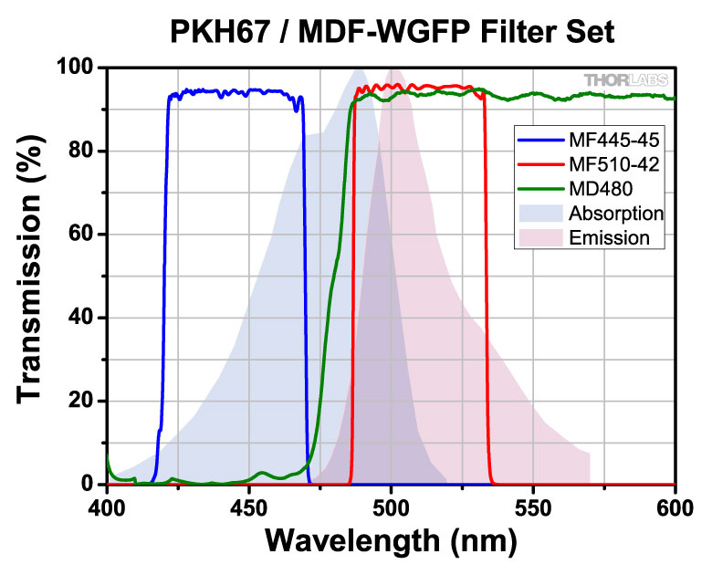
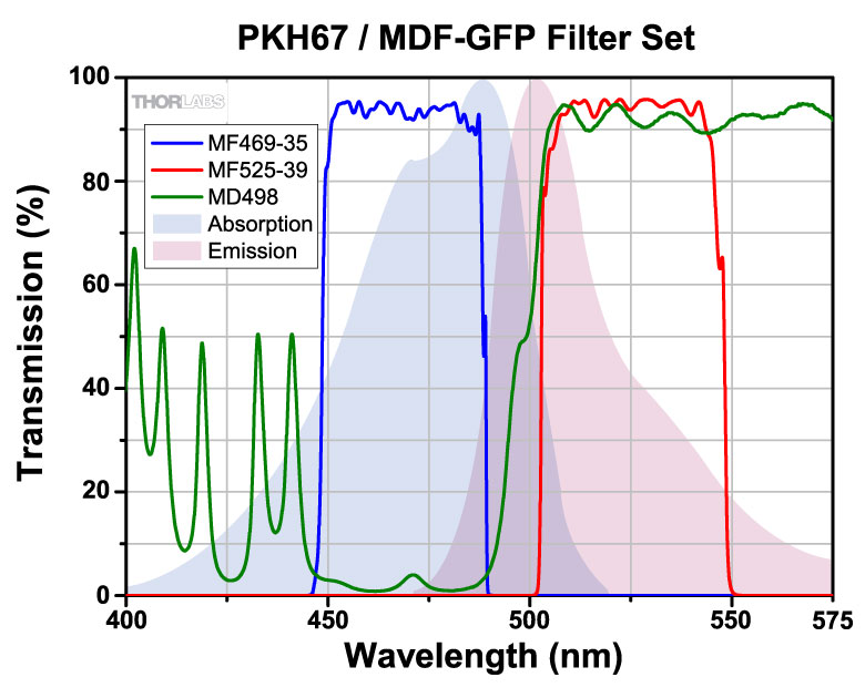
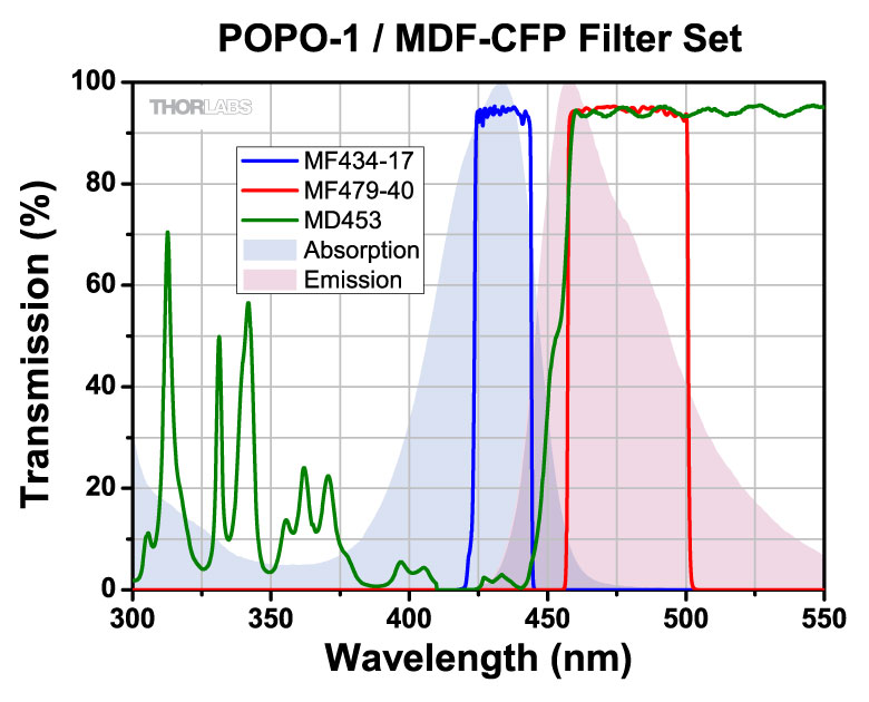
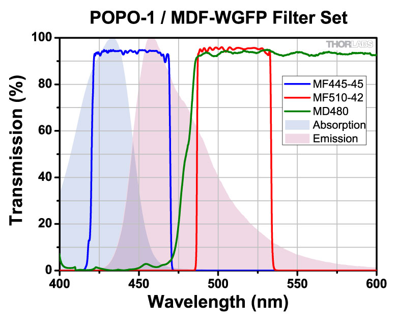
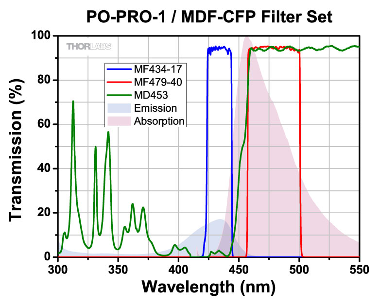
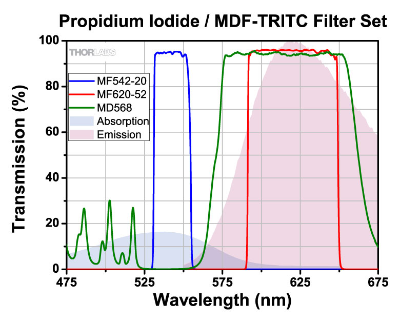
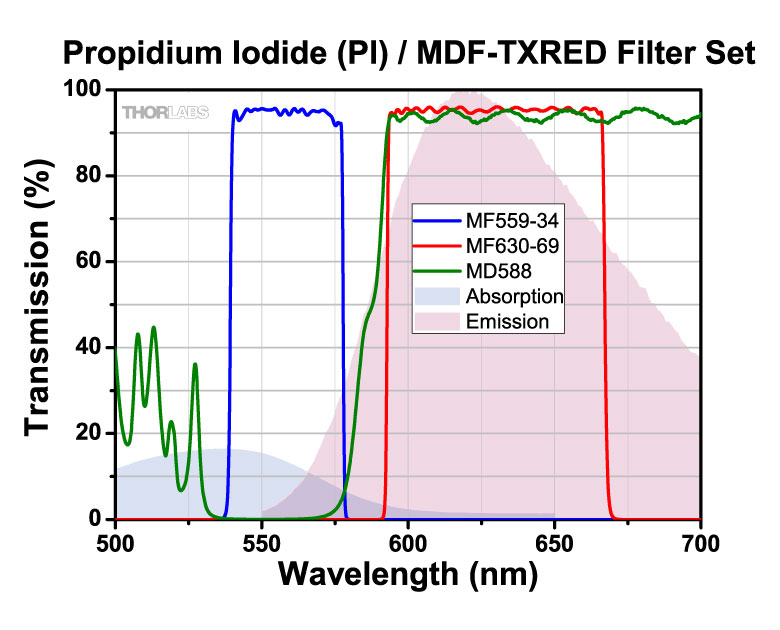
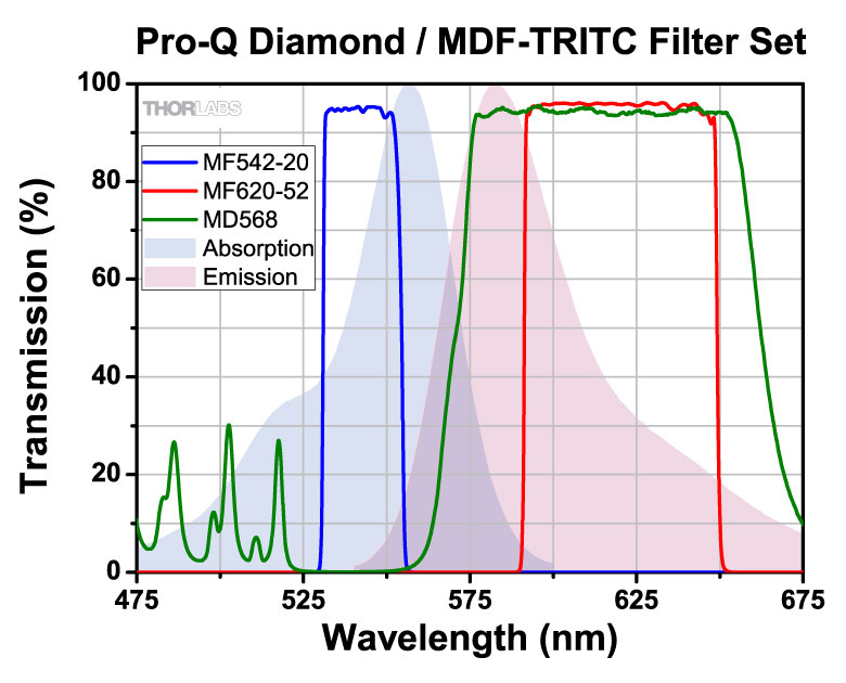
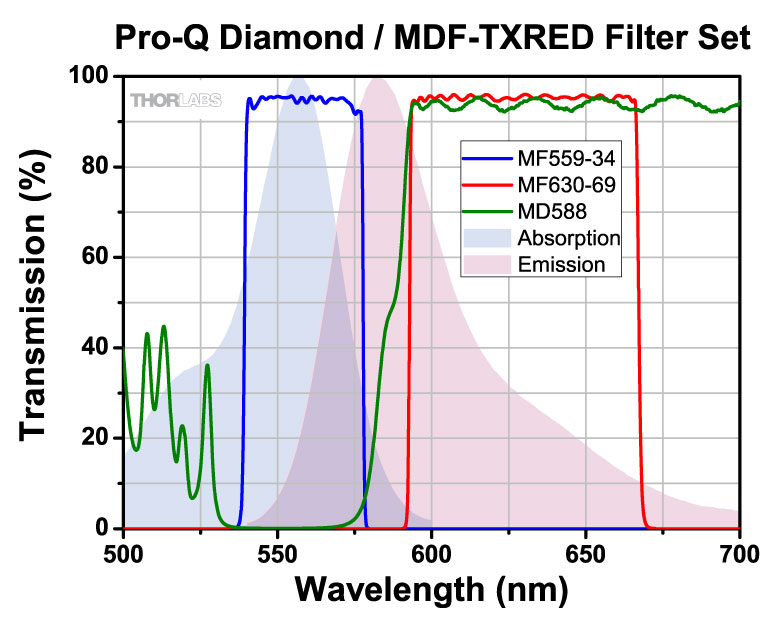
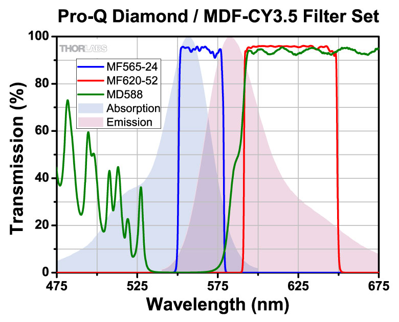
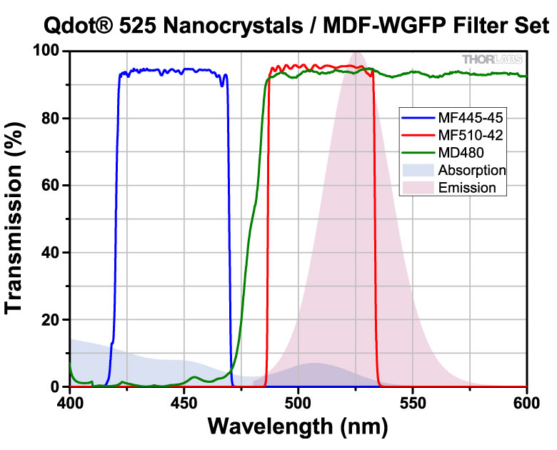
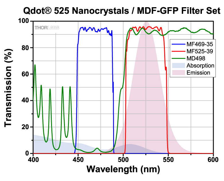
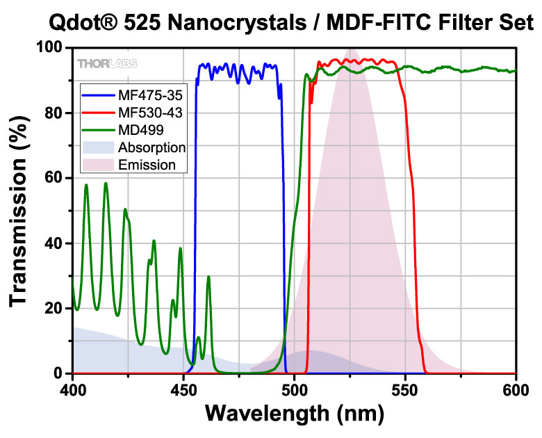
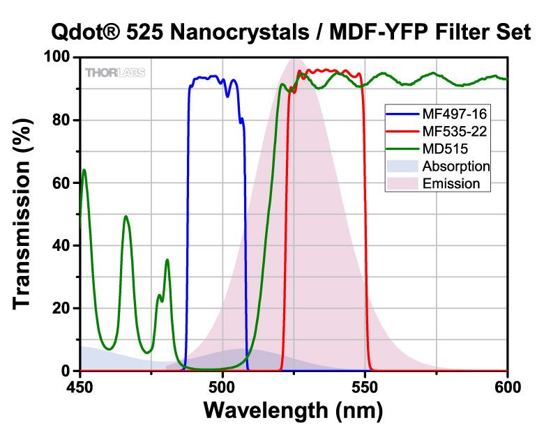
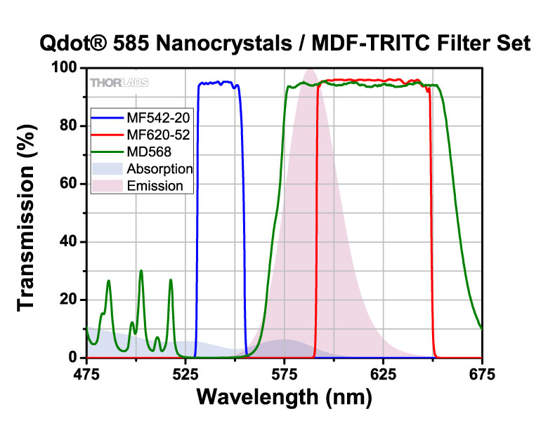
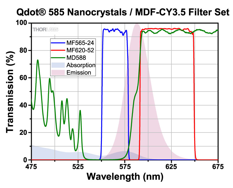
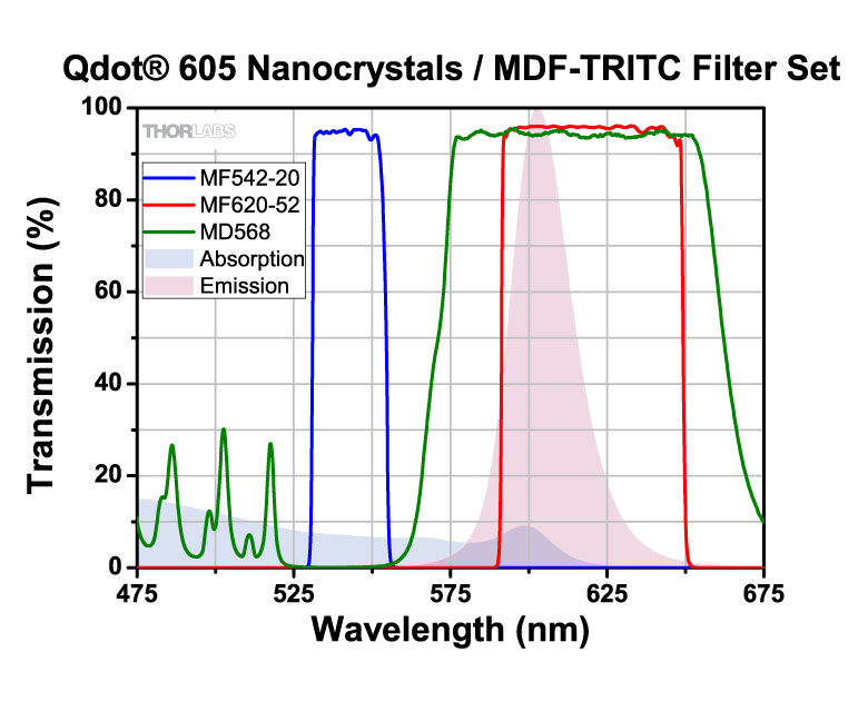
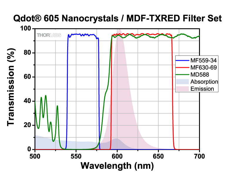
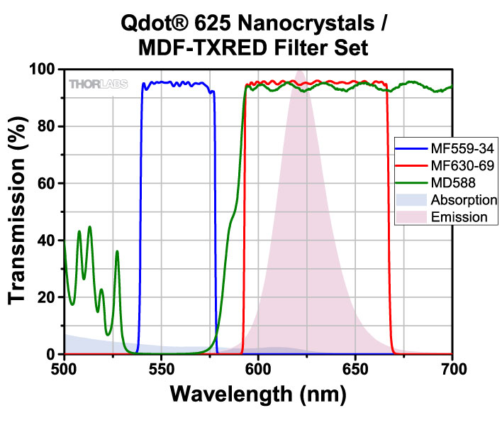
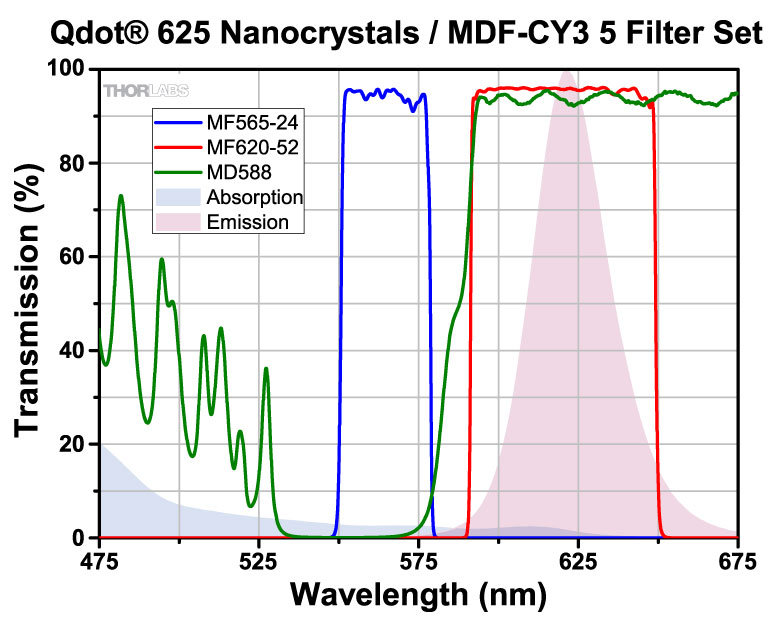
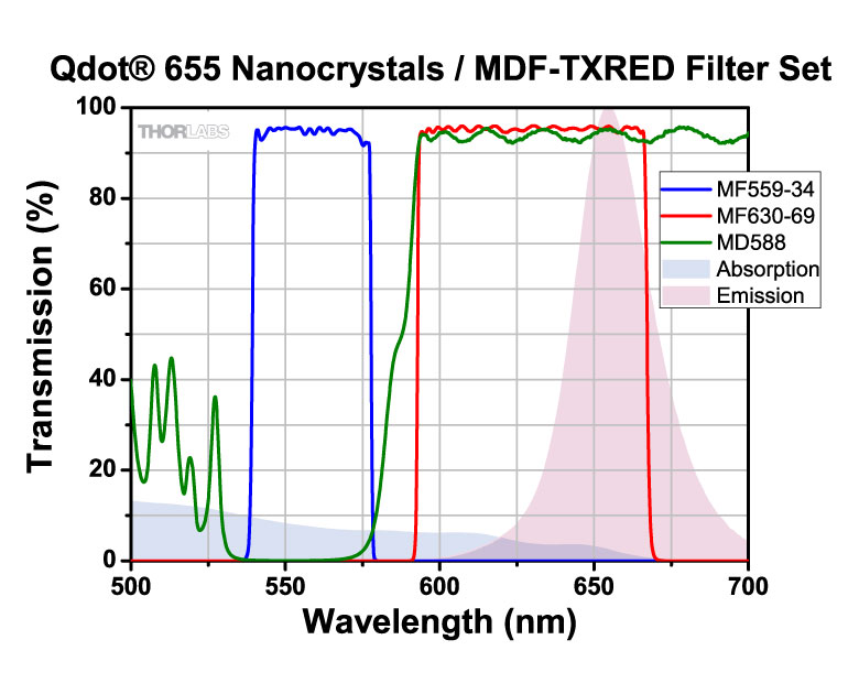
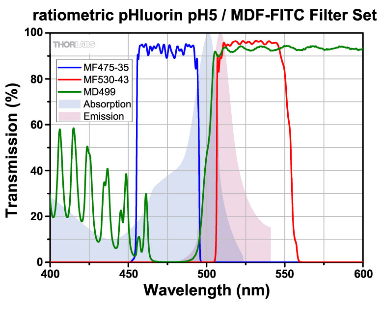
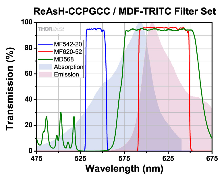
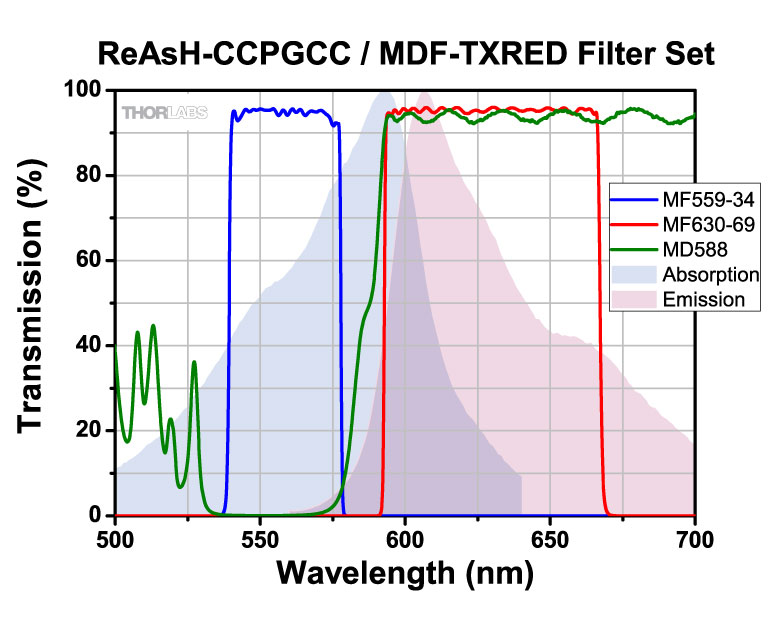
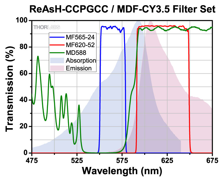
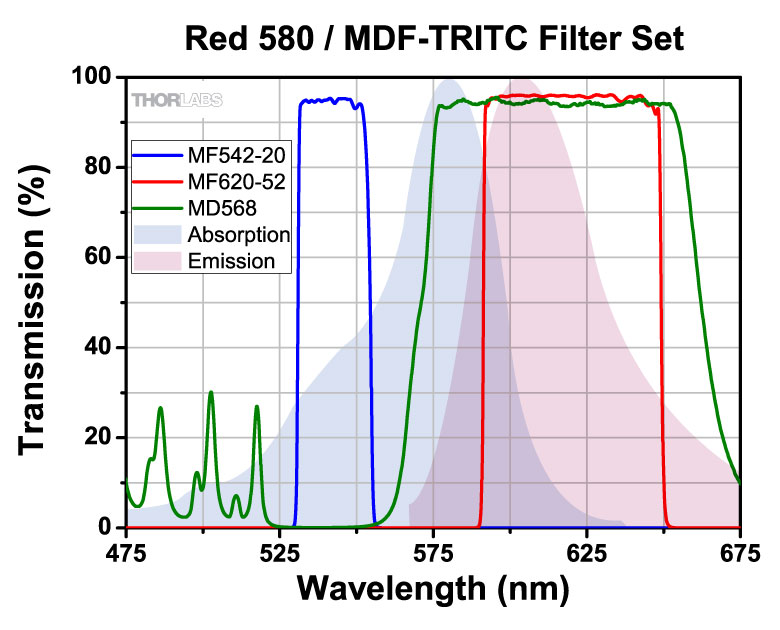
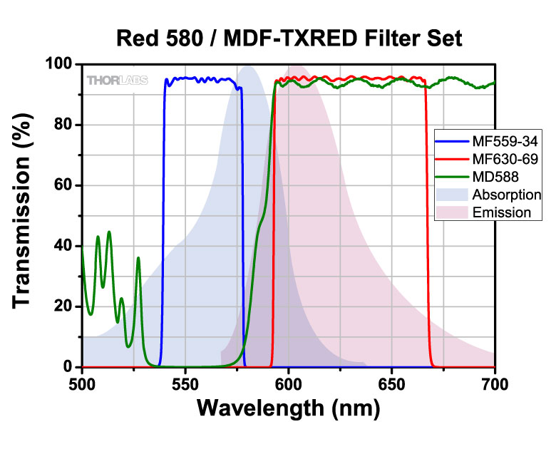
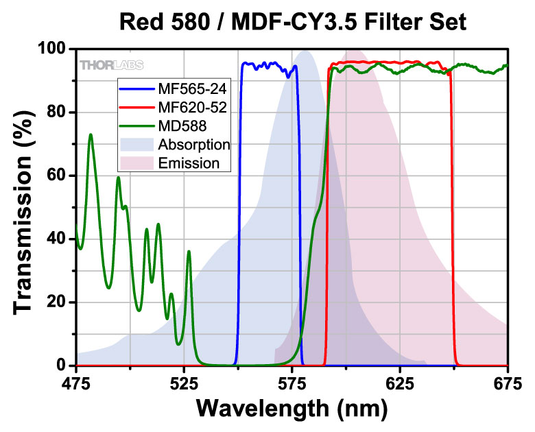
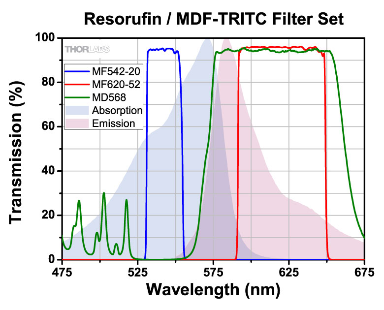
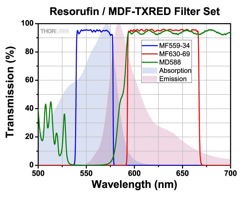
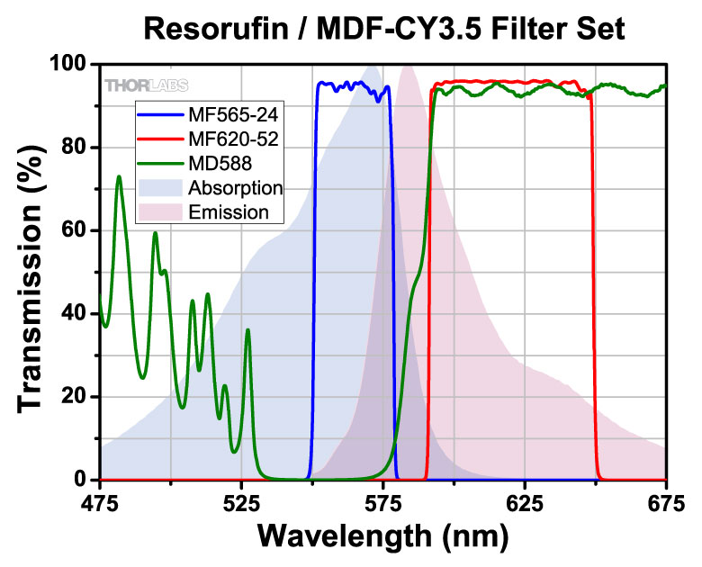
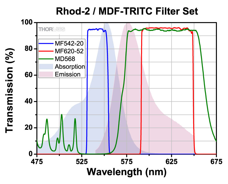
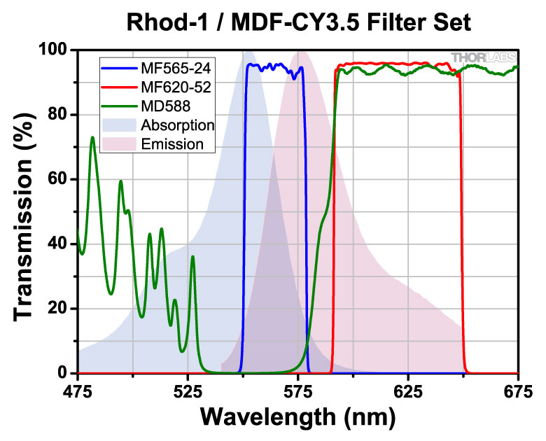
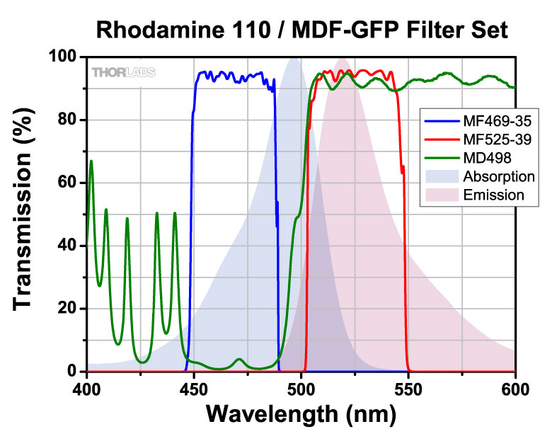
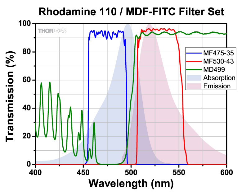
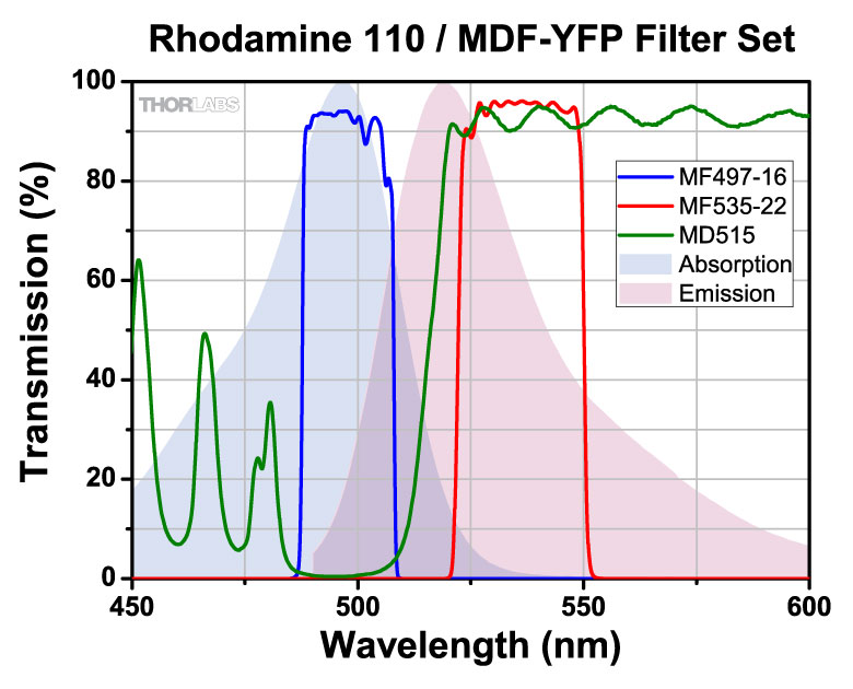
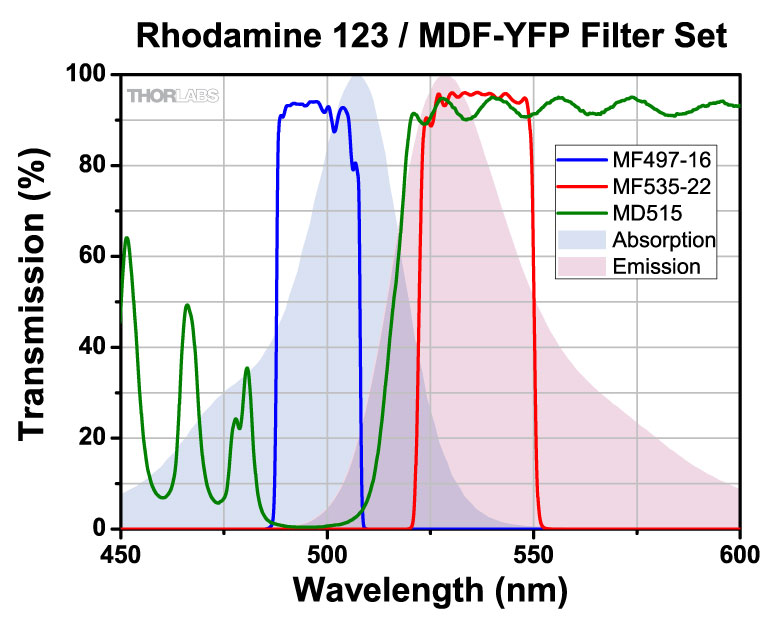
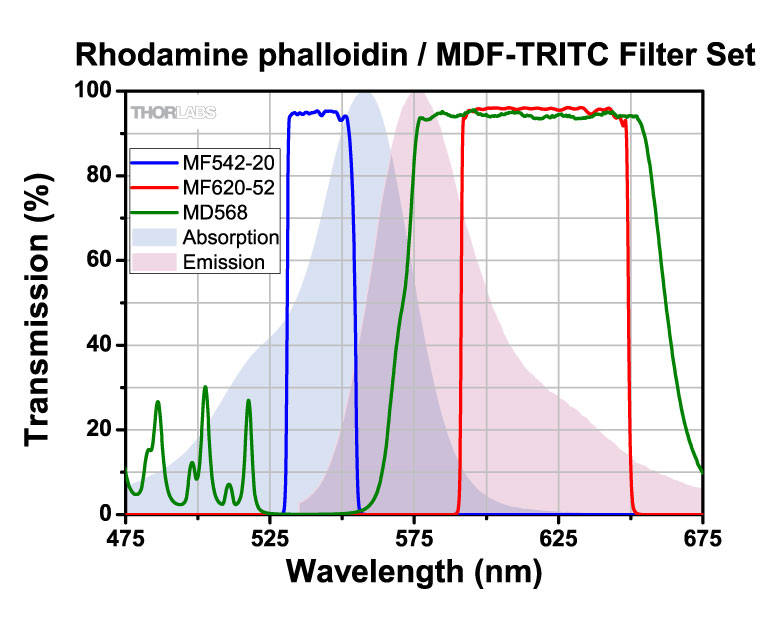
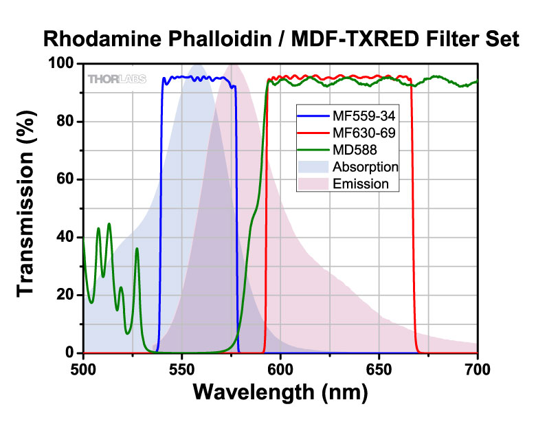
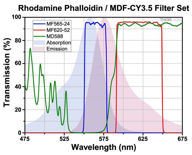
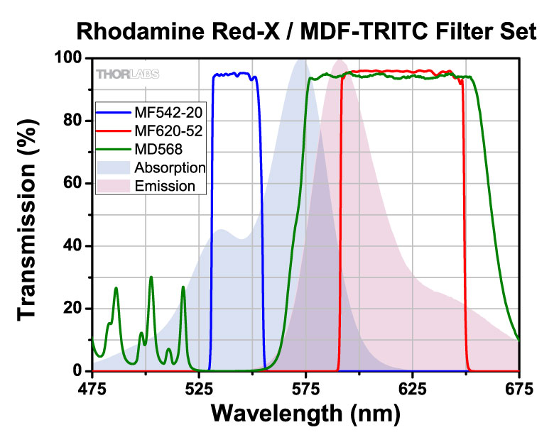
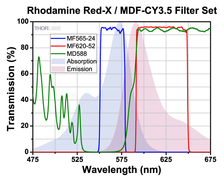
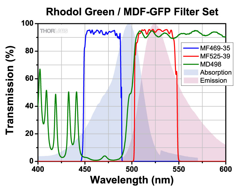
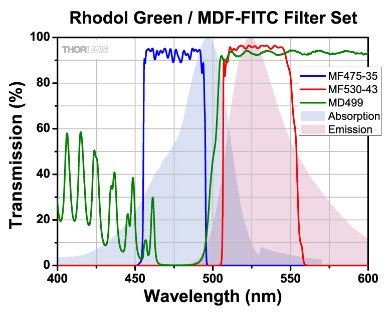
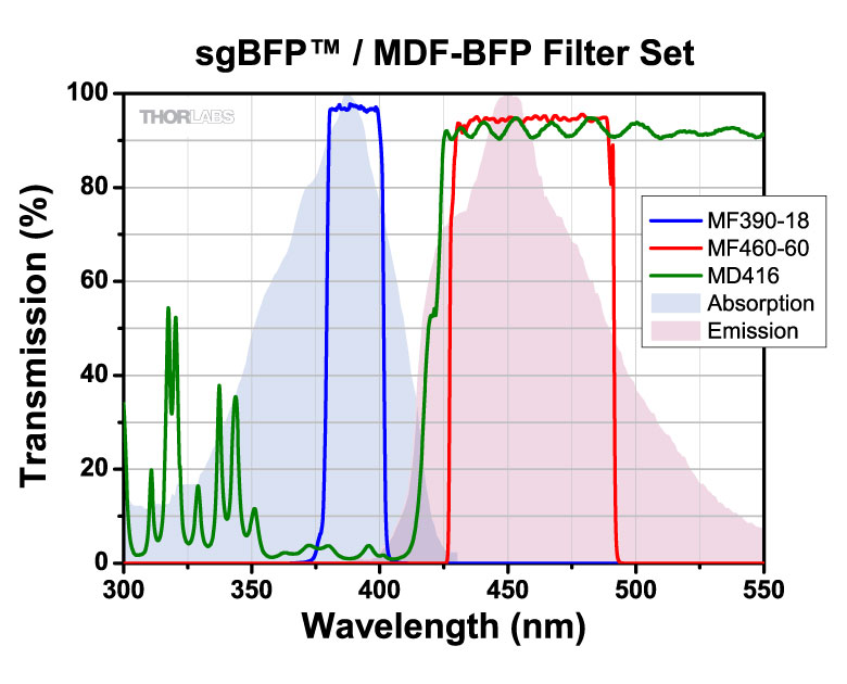
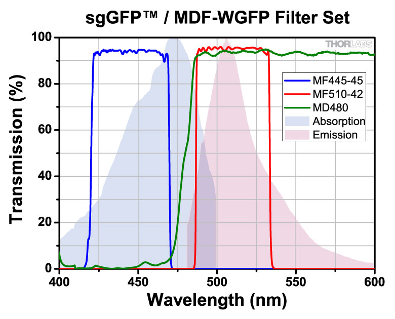
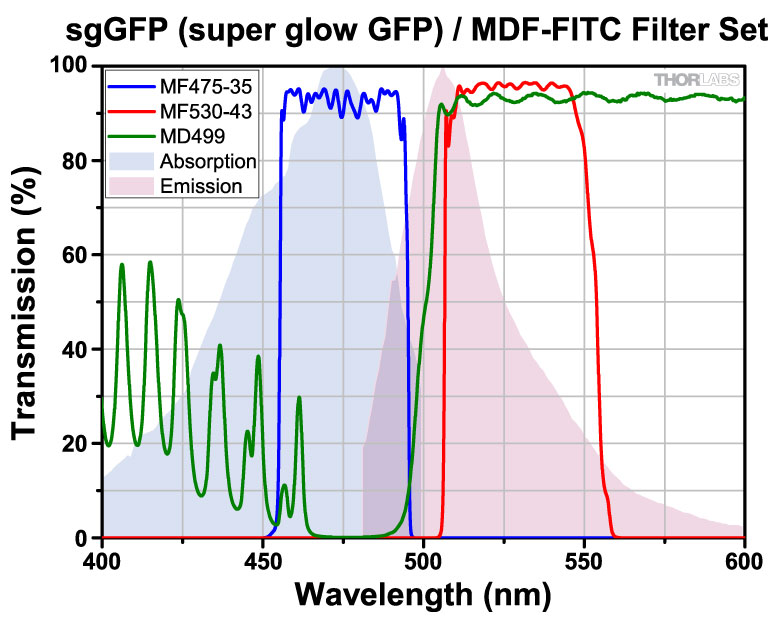
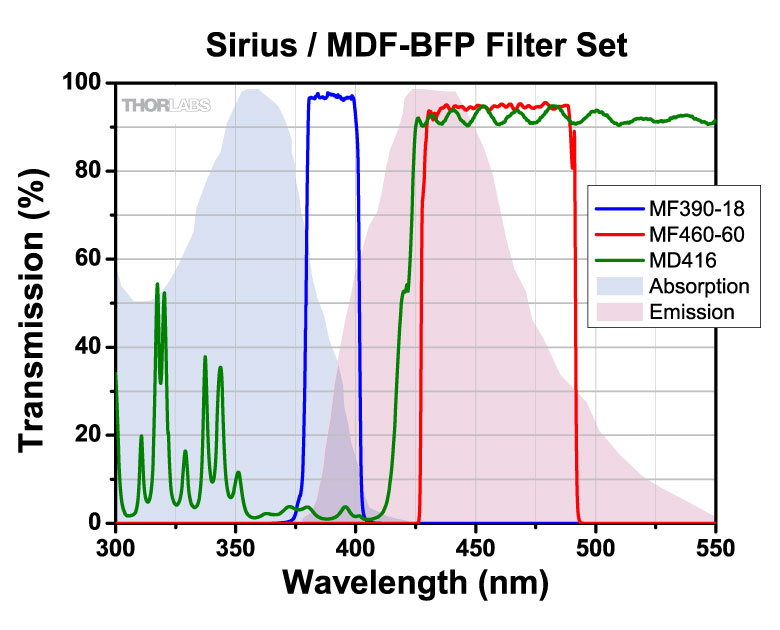
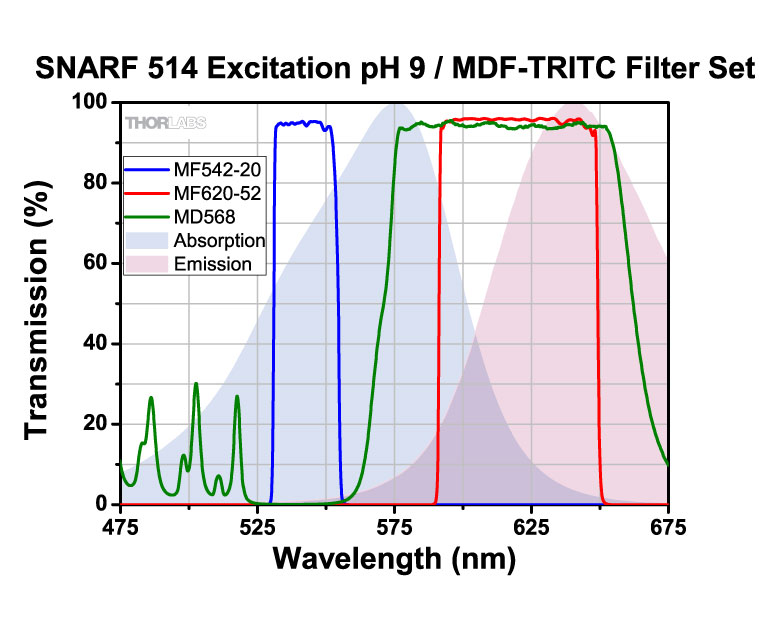
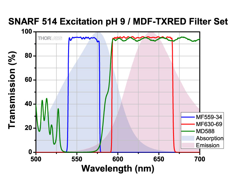
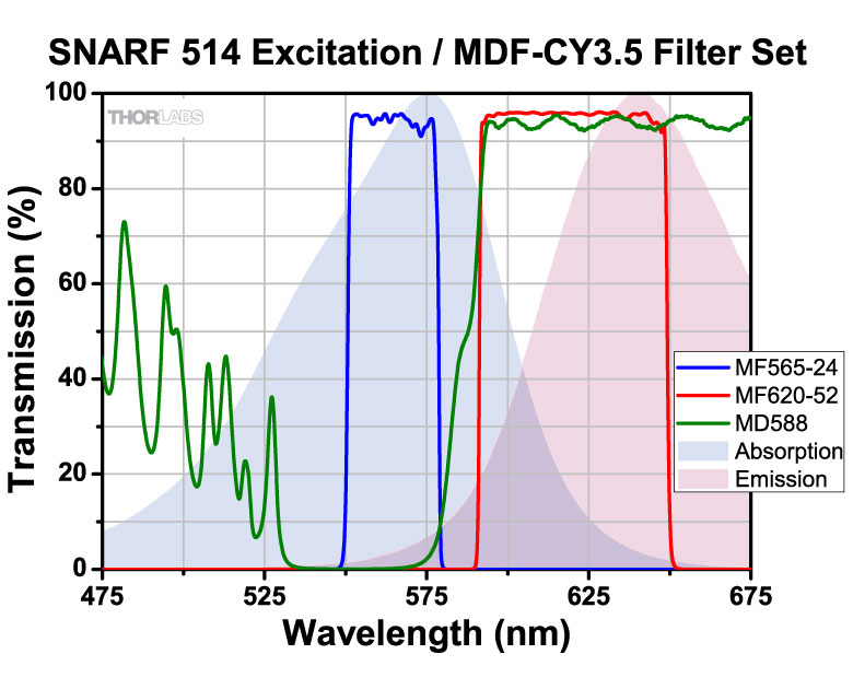
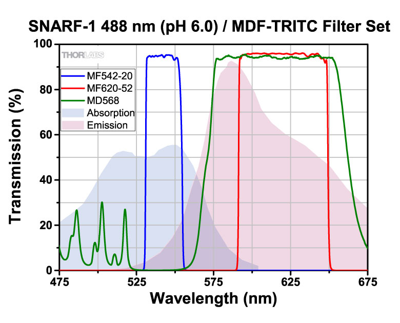
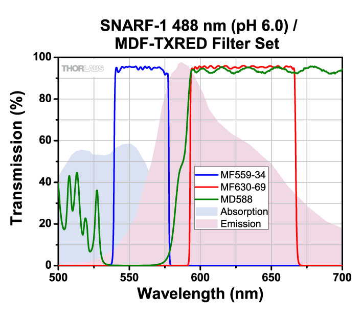
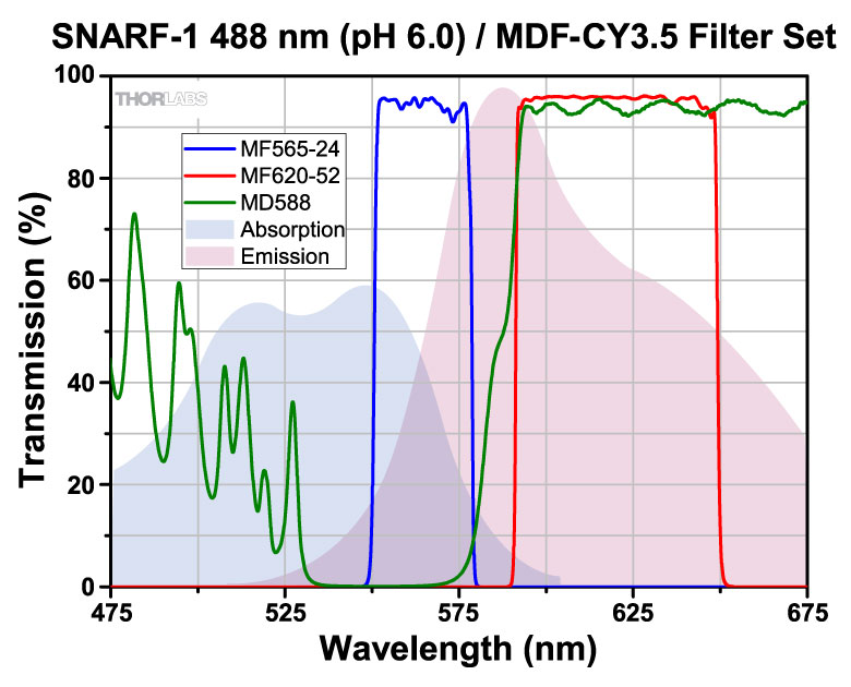
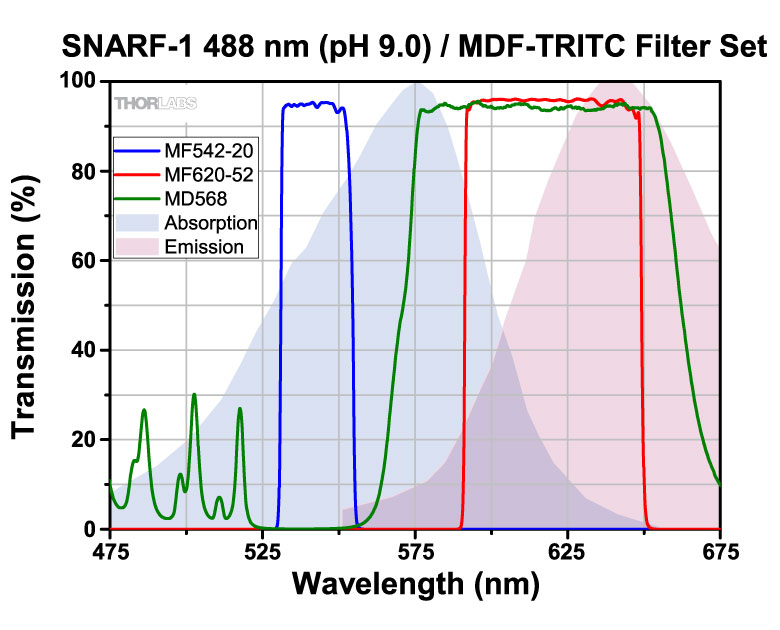
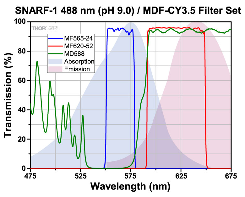
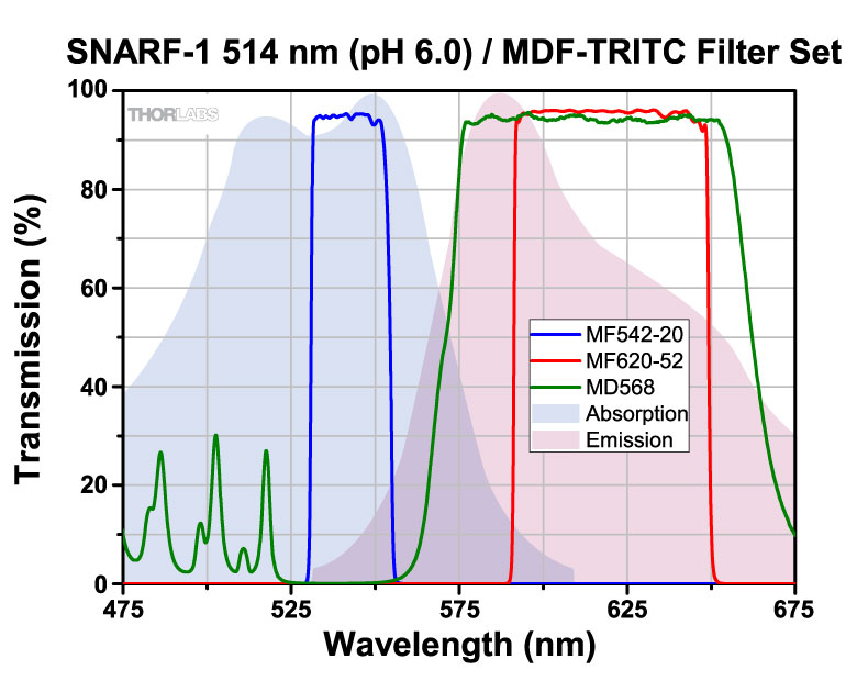
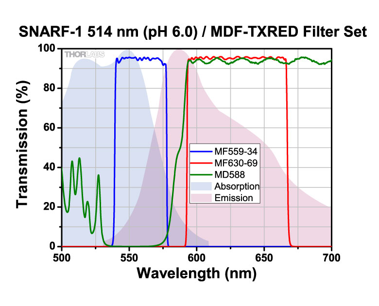
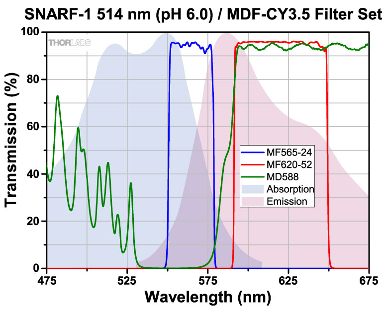
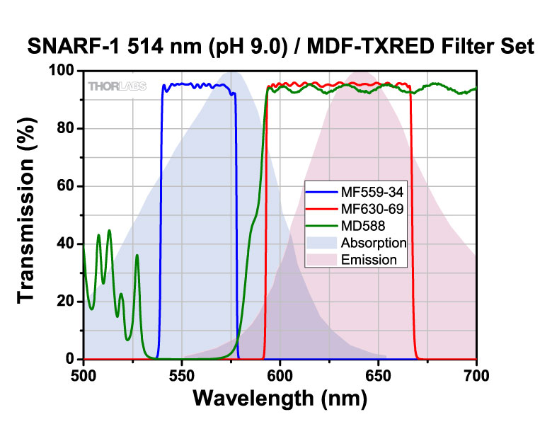
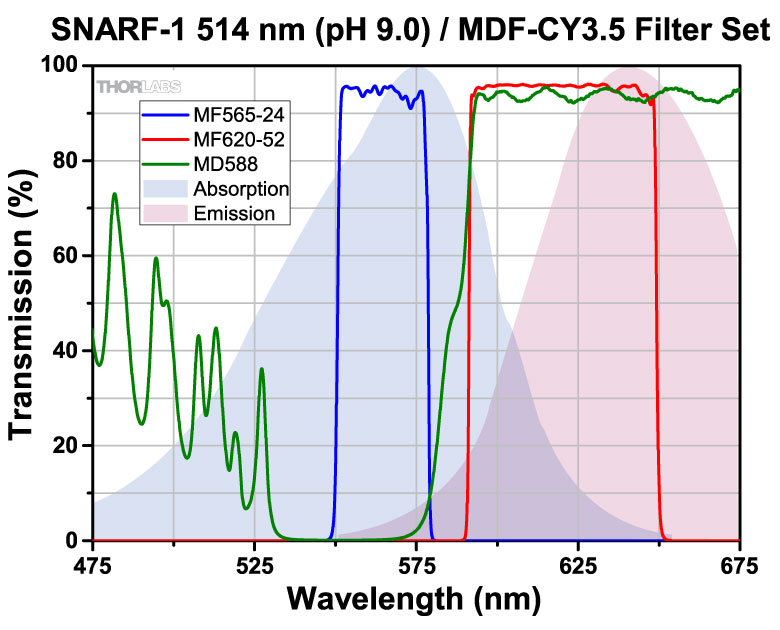
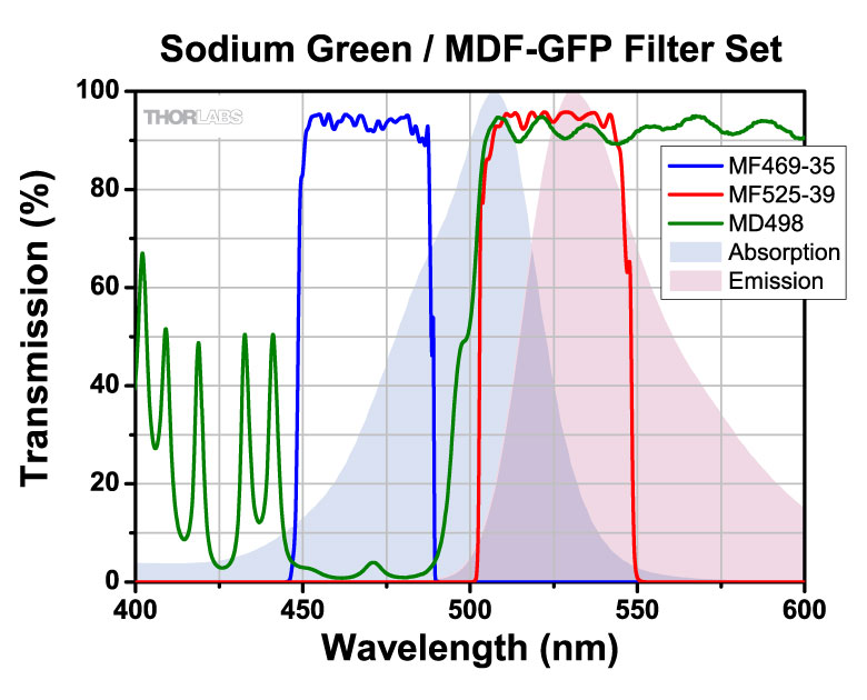
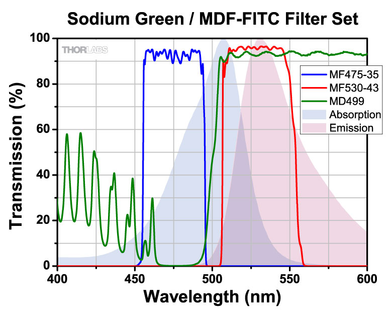
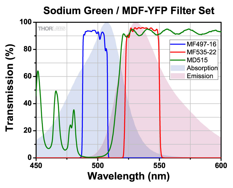
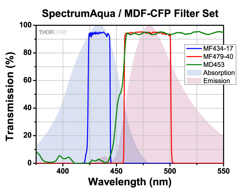
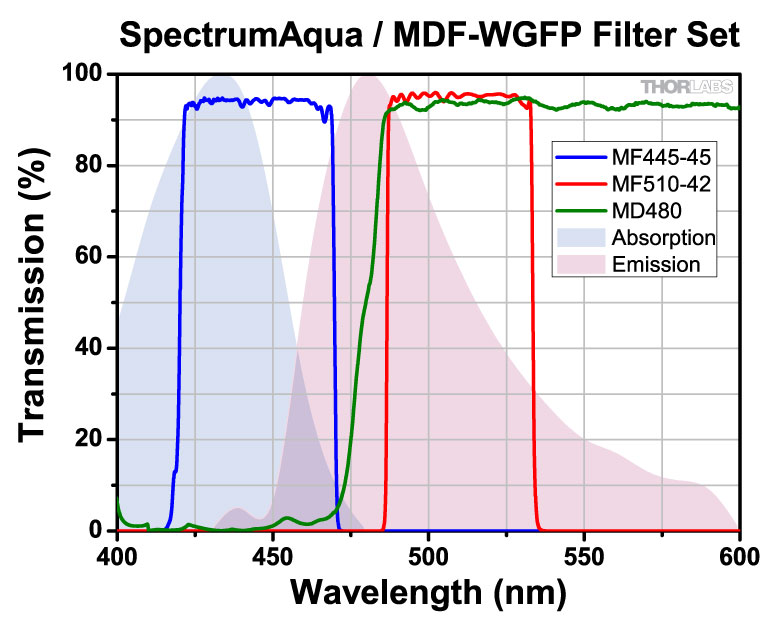
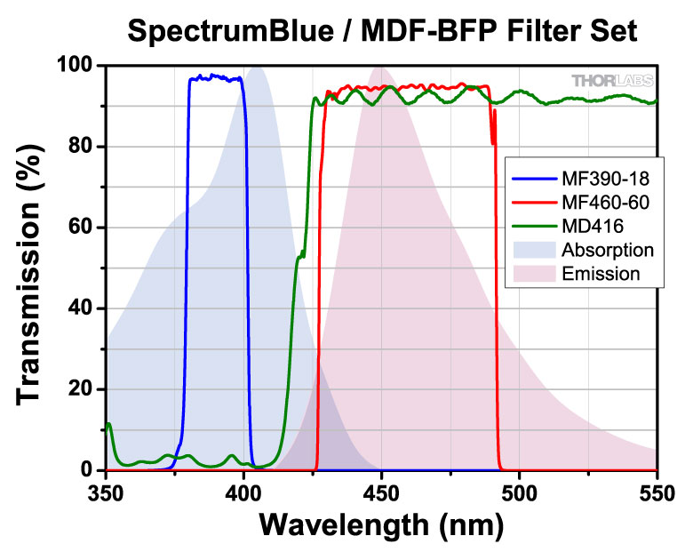
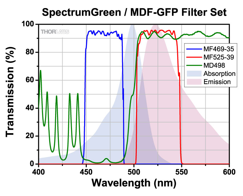
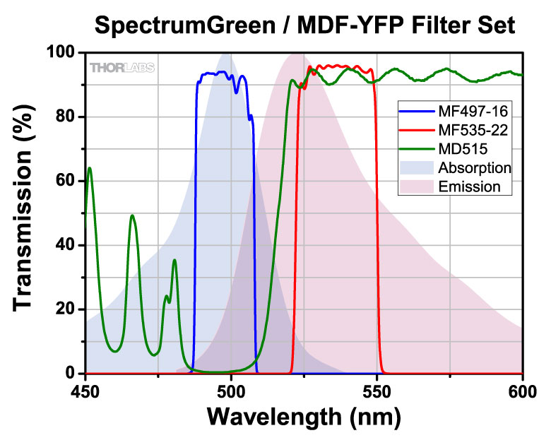
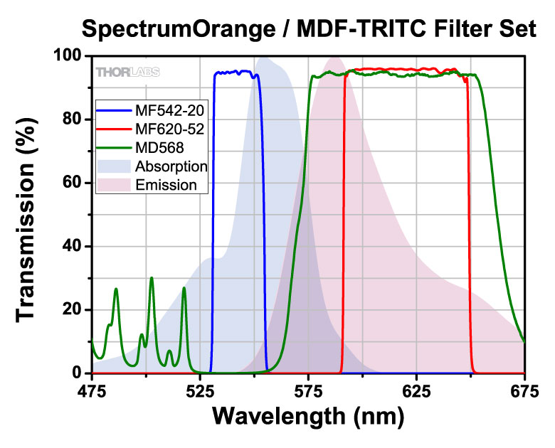
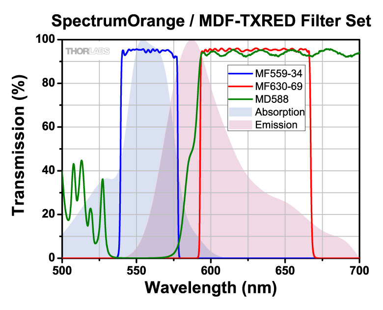
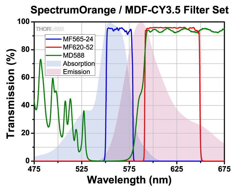
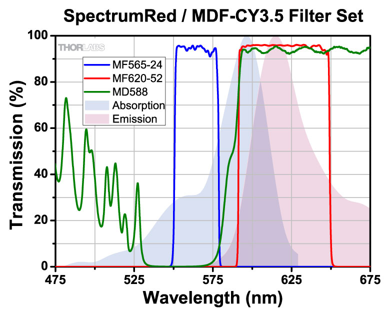
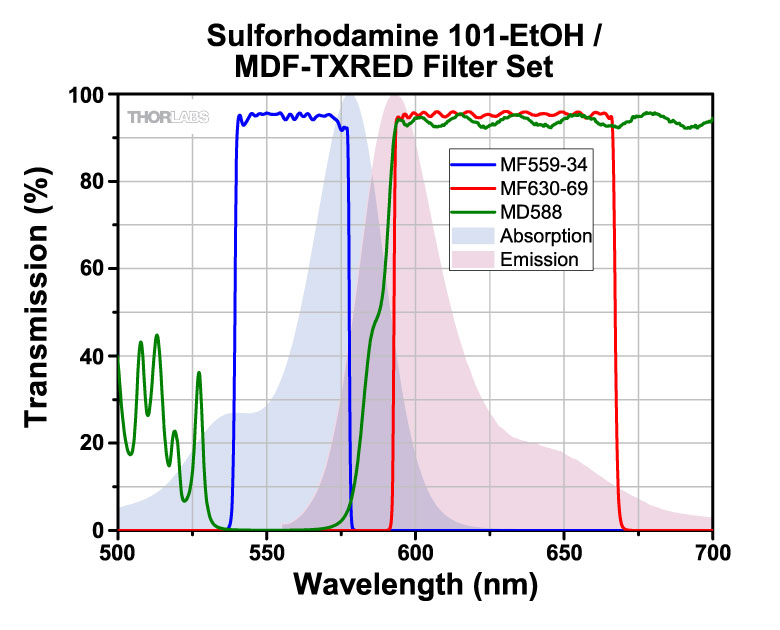
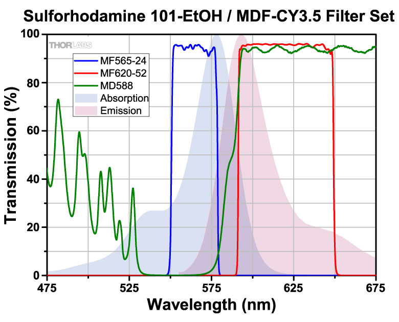
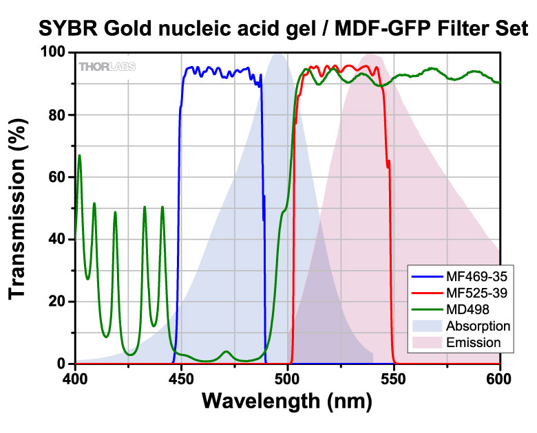
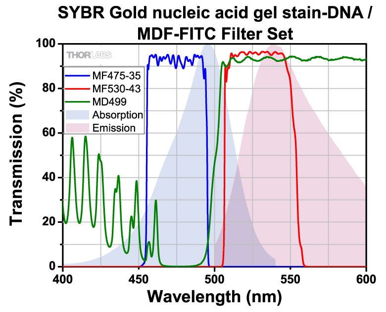
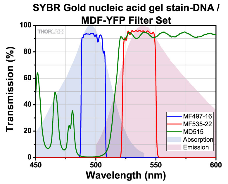
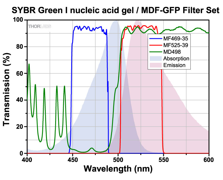
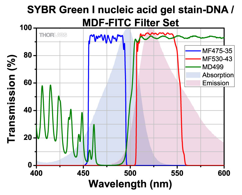
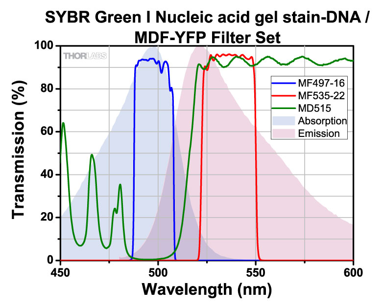
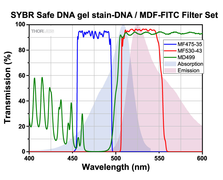
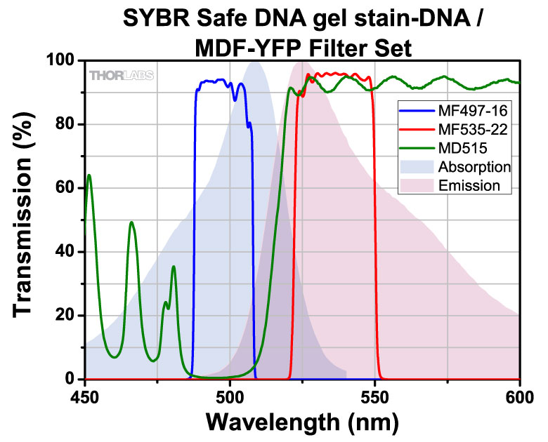
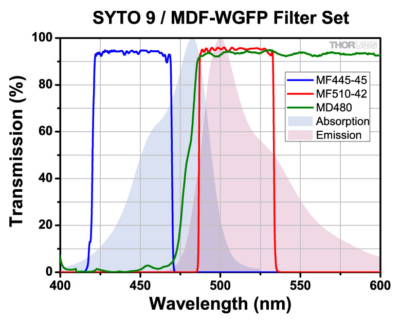
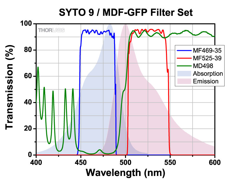
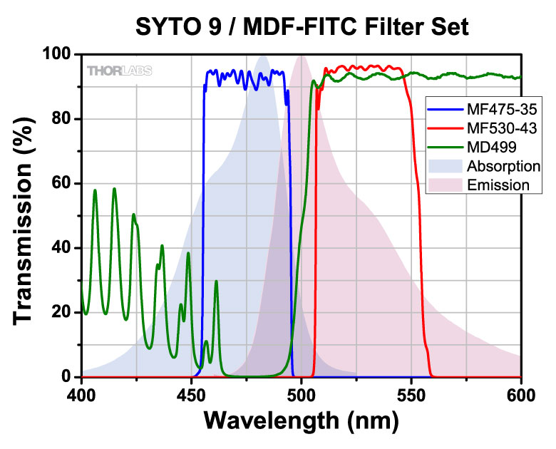
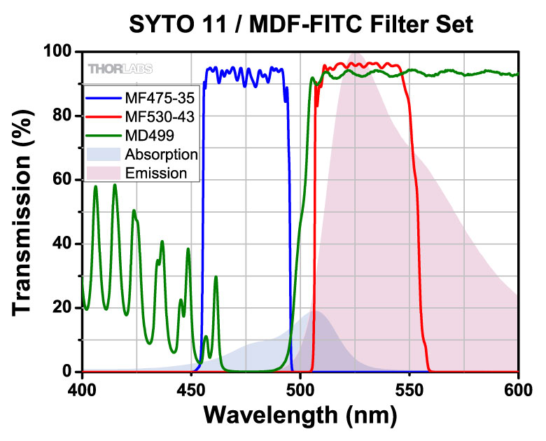
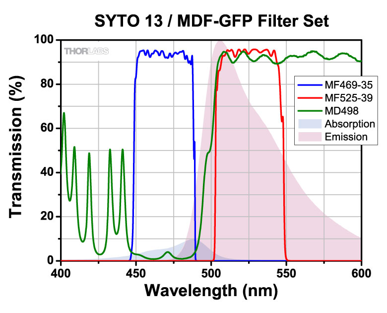
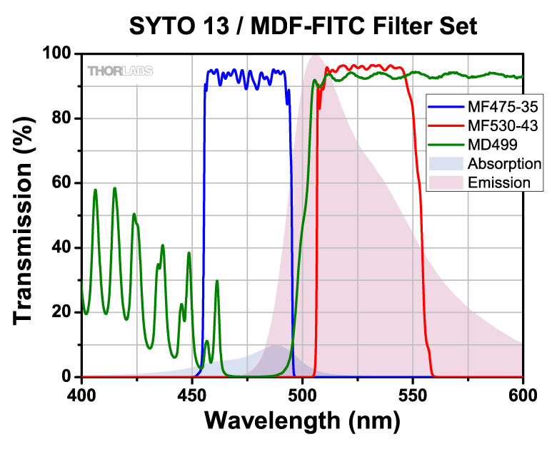
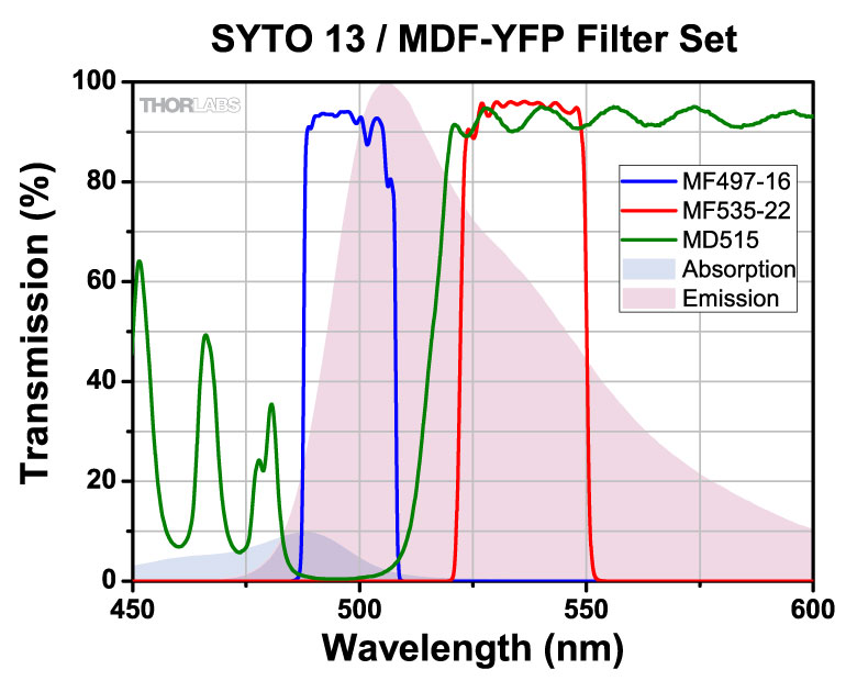
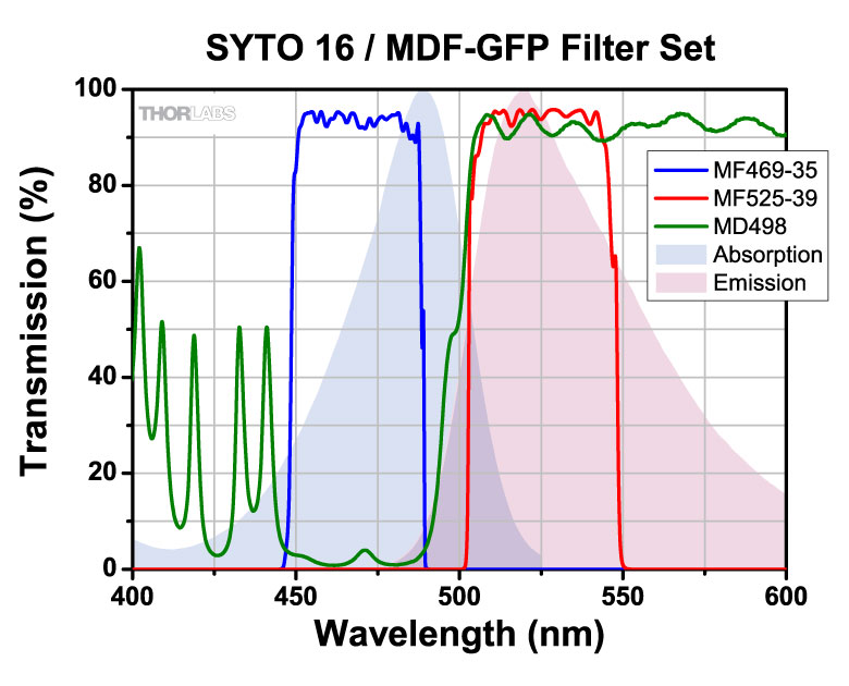
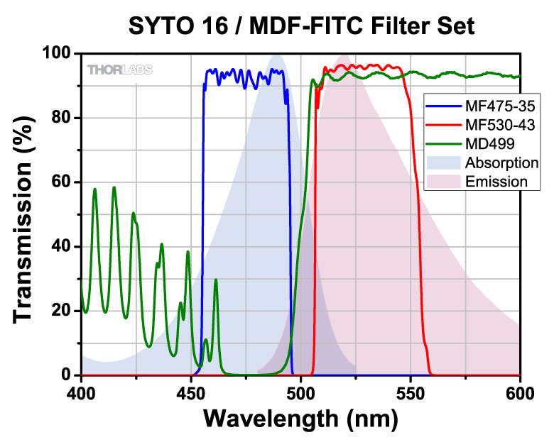
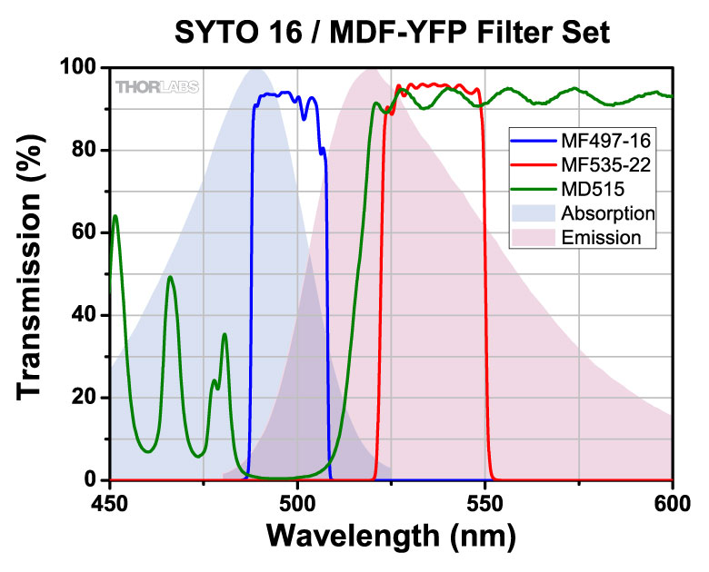
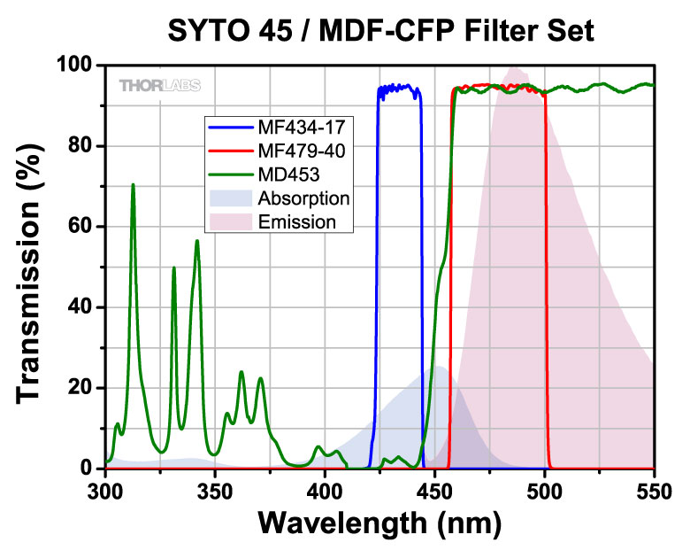
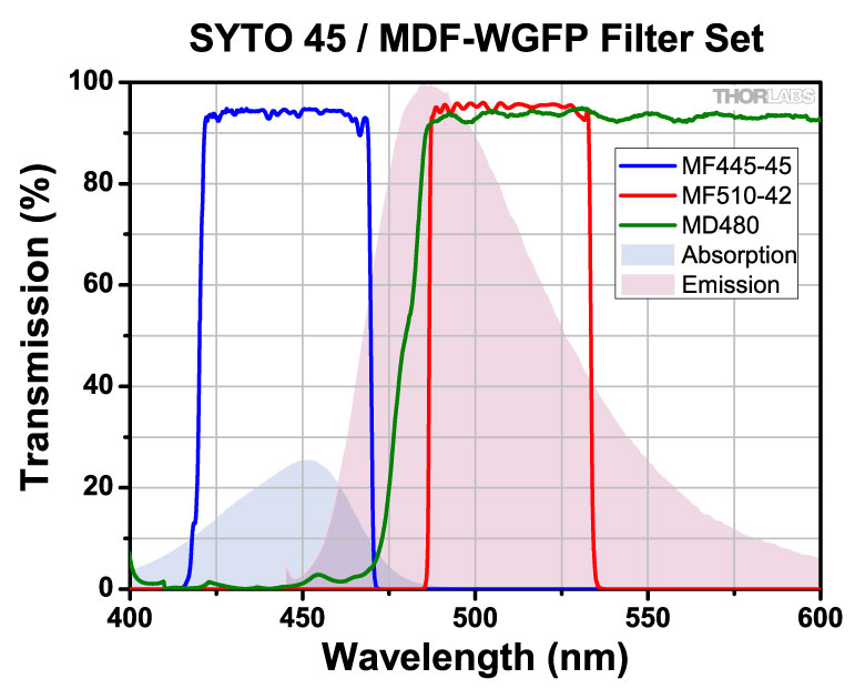
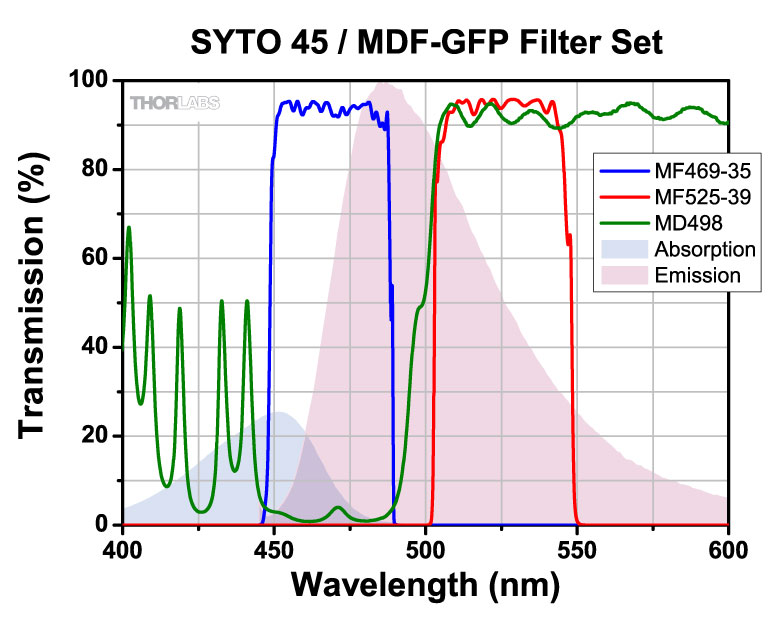
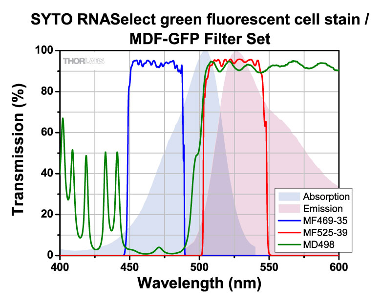
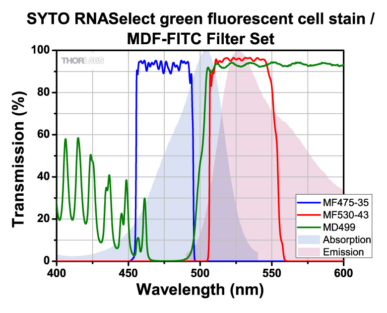
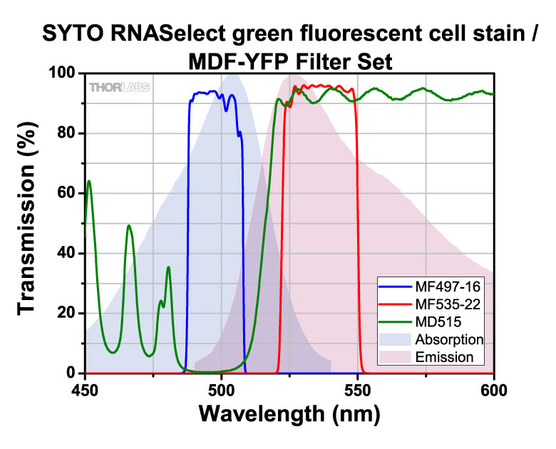
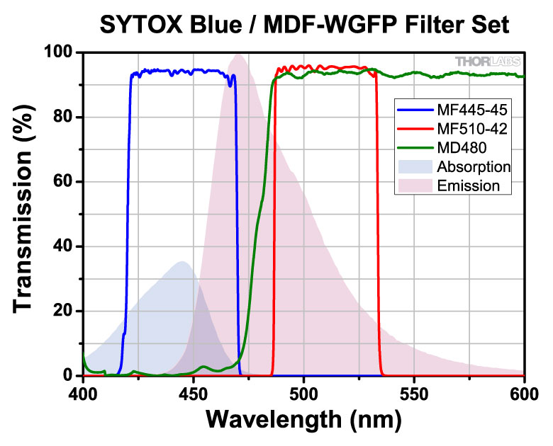
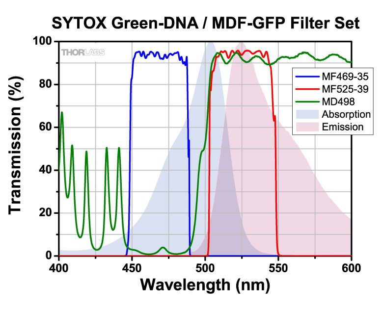
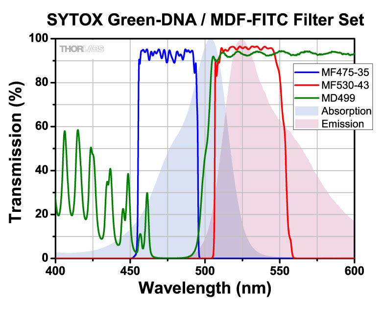
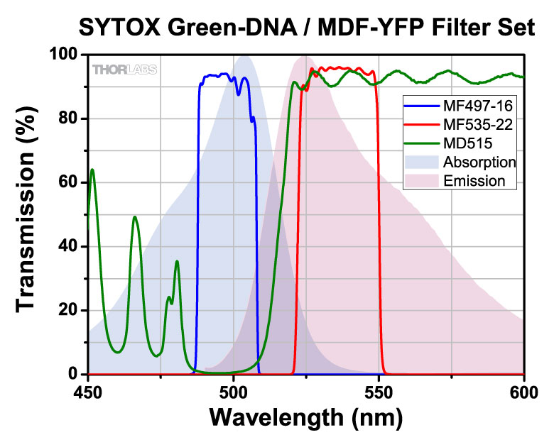
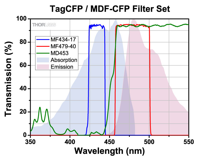
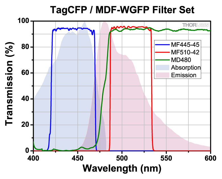
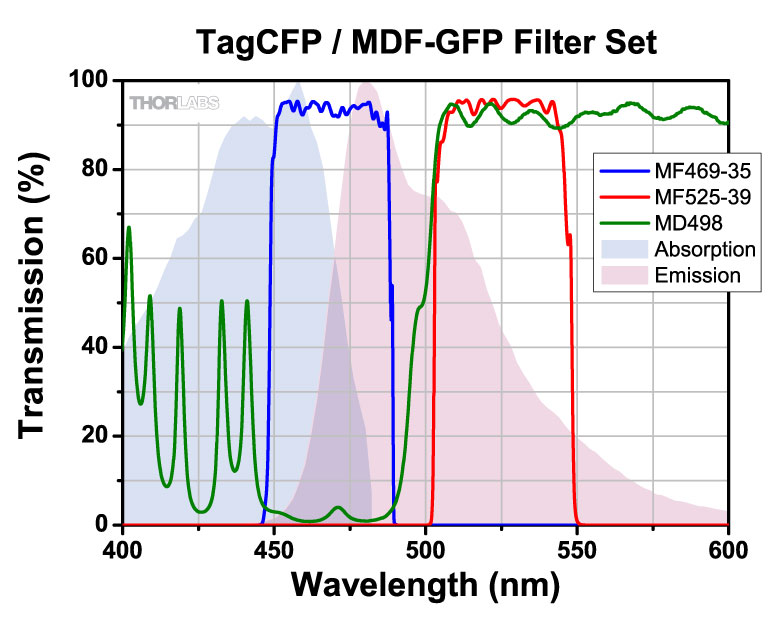
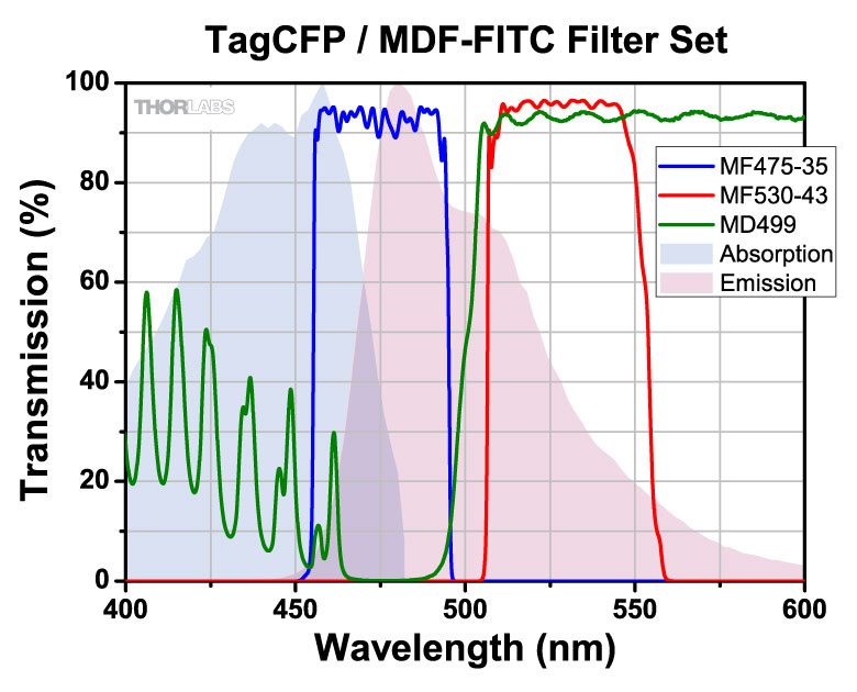
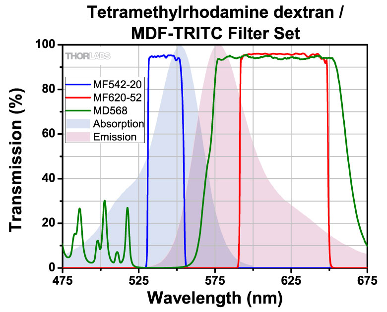
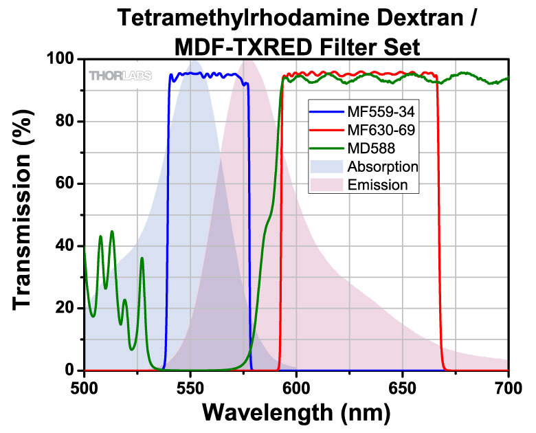
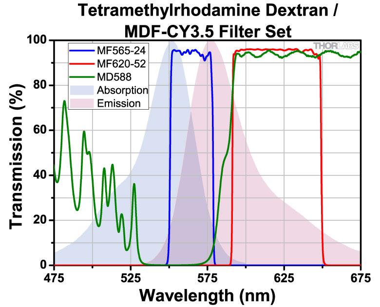
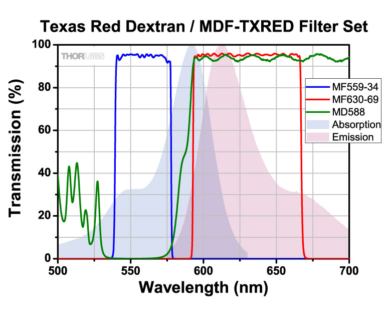
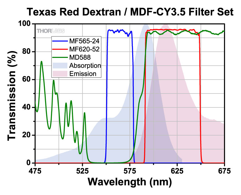
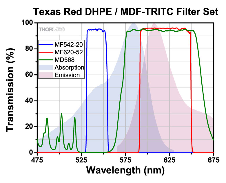
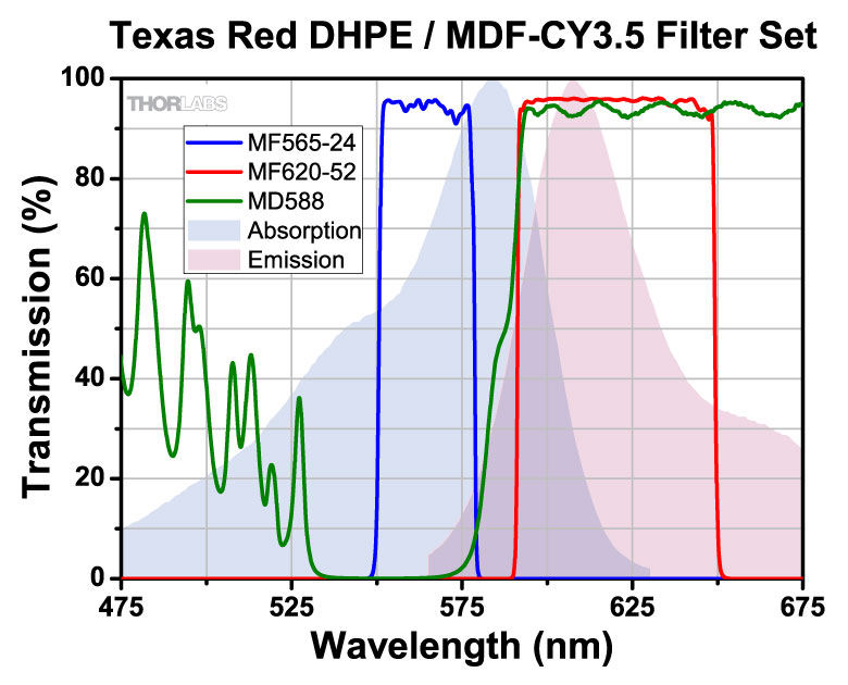
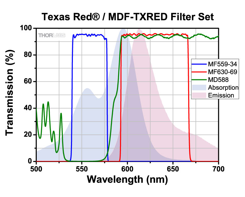
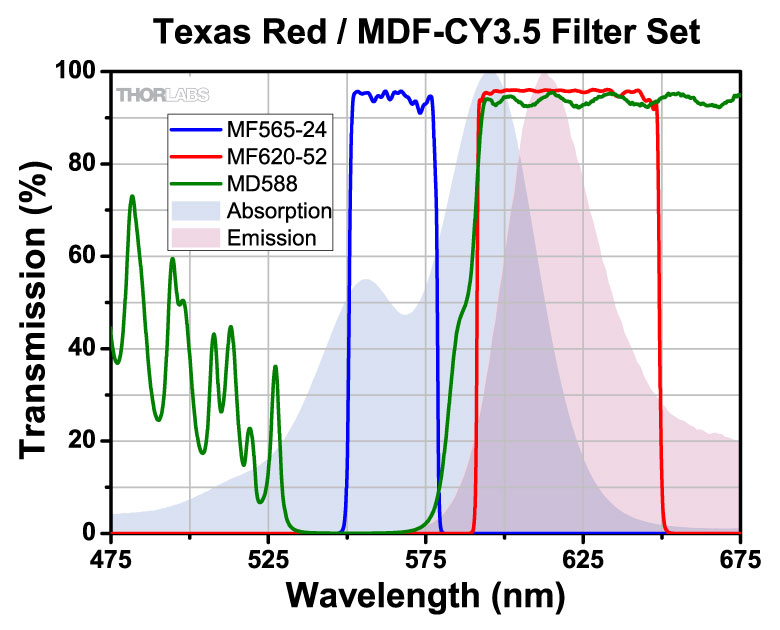
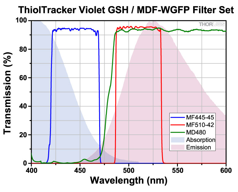
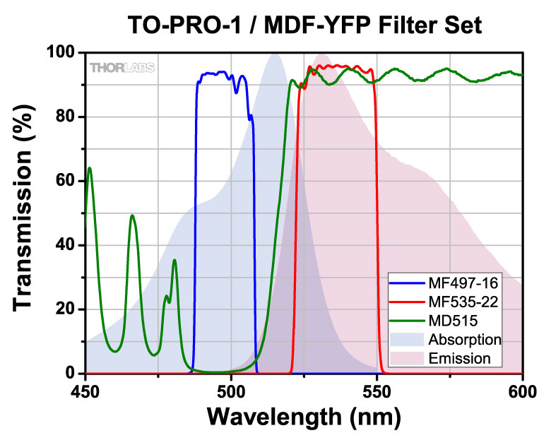
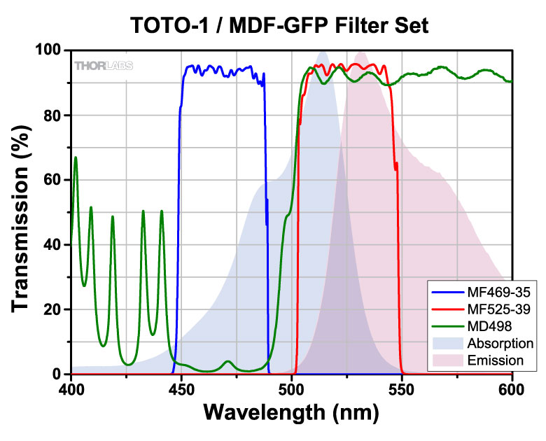
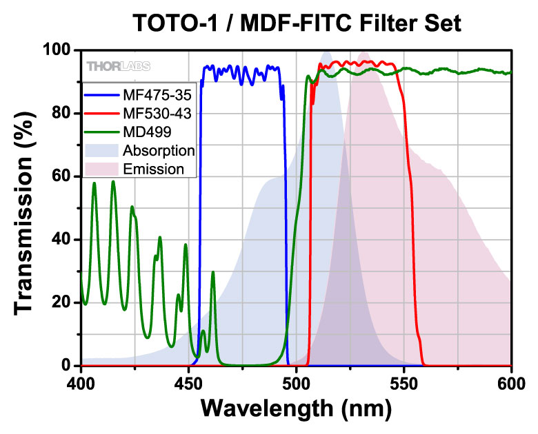
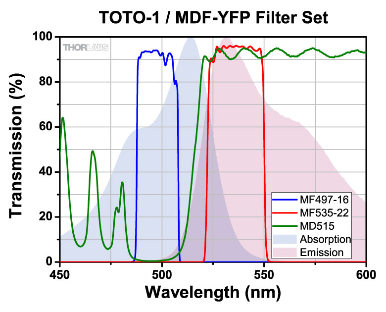
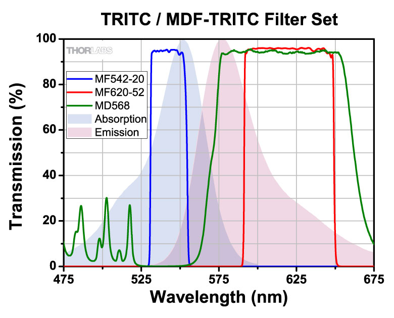
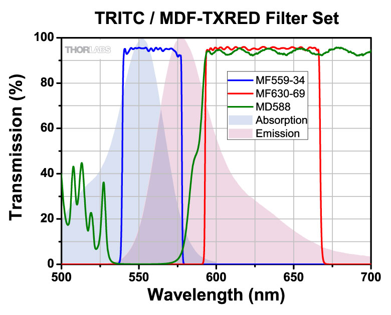
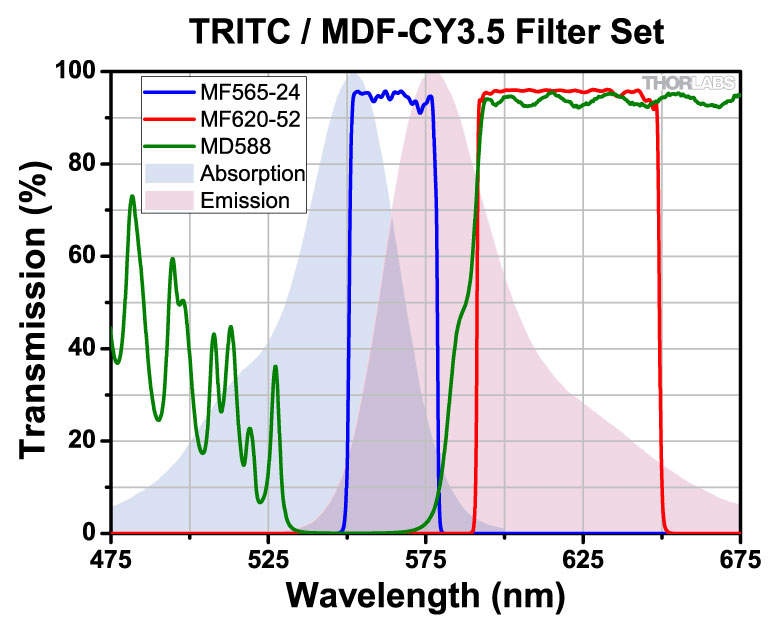
.jpg)
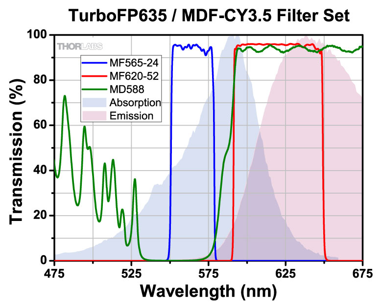
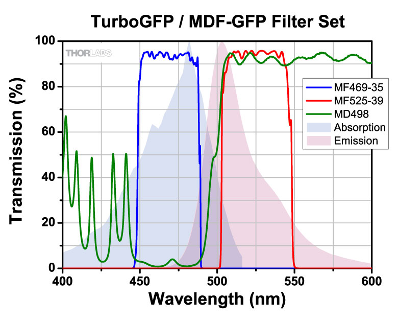
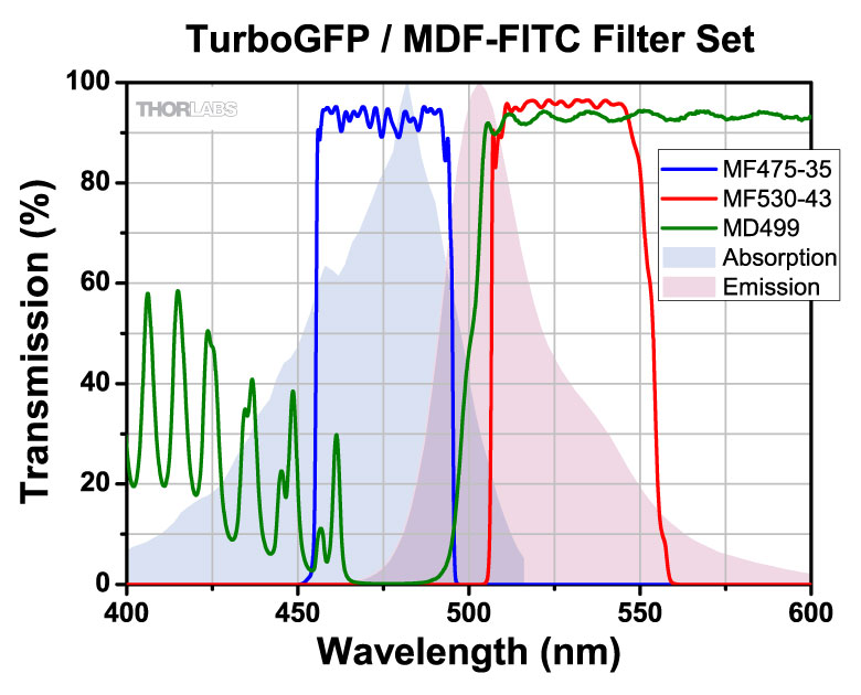
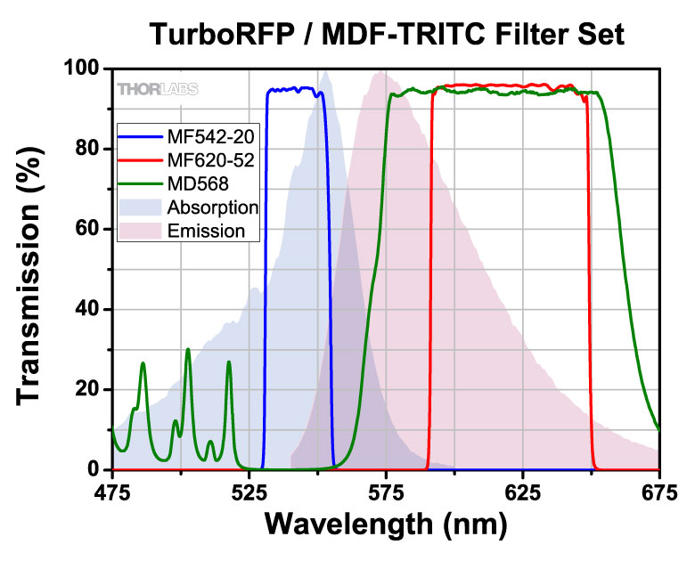
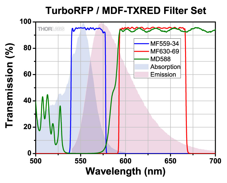
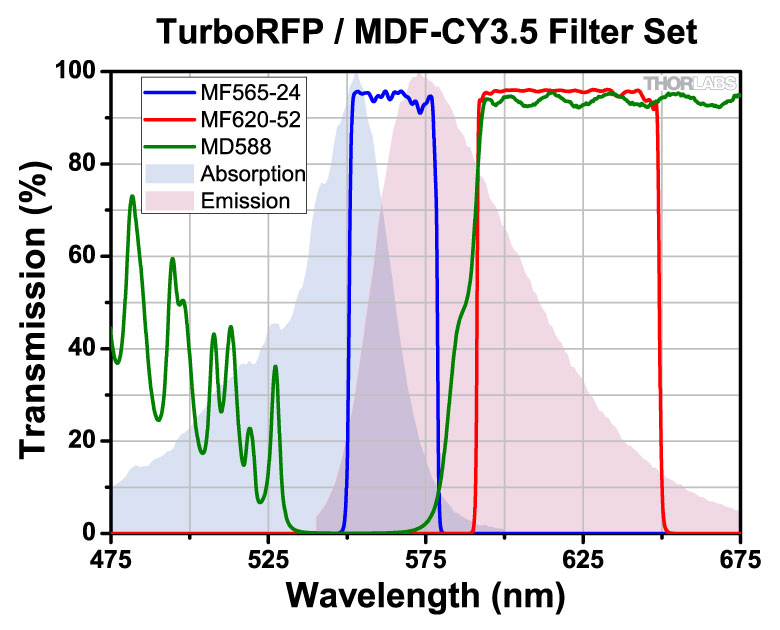
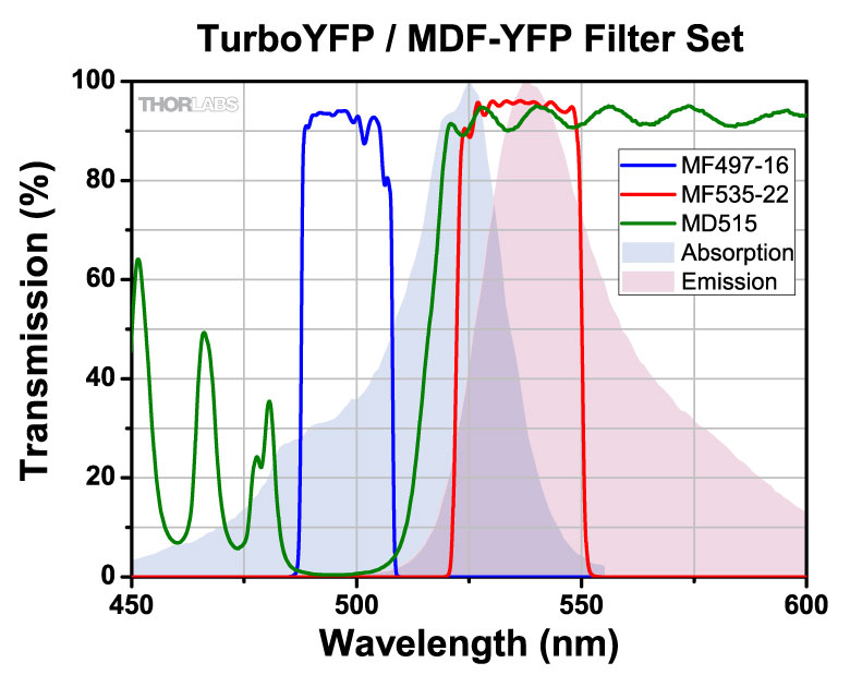
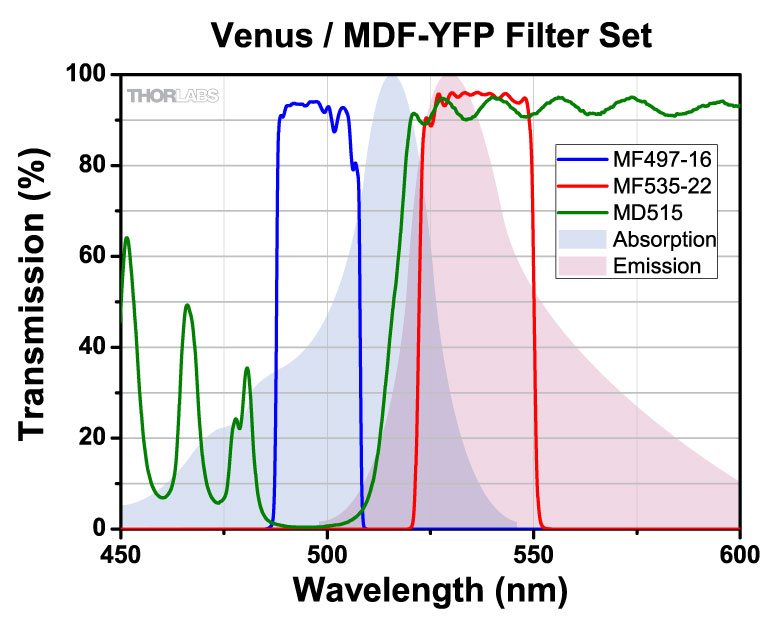
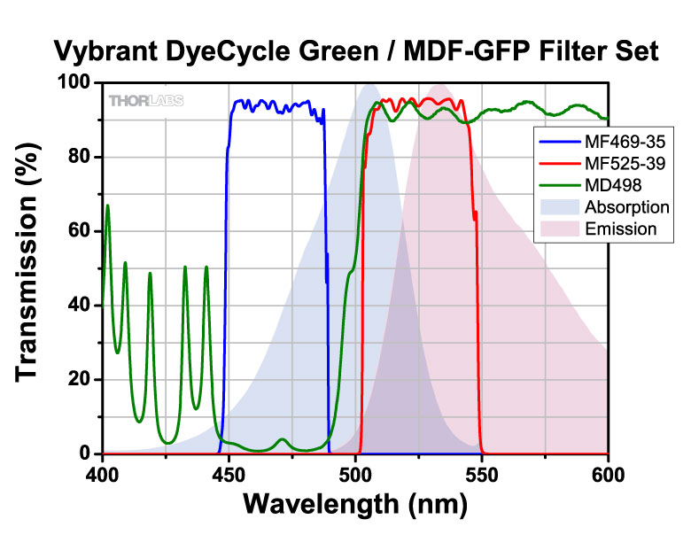
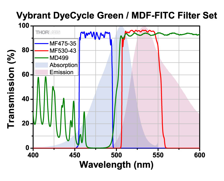
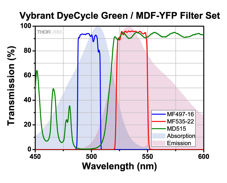
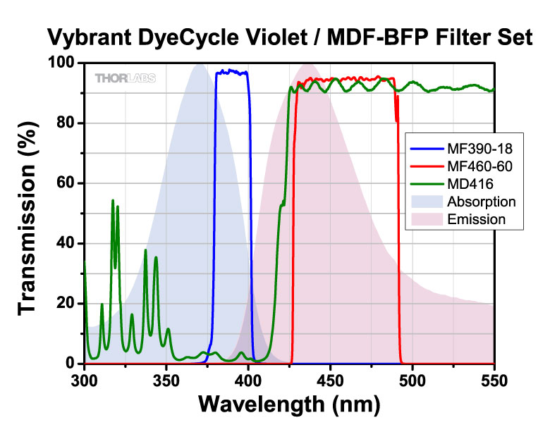
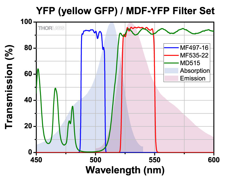
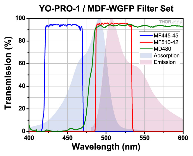
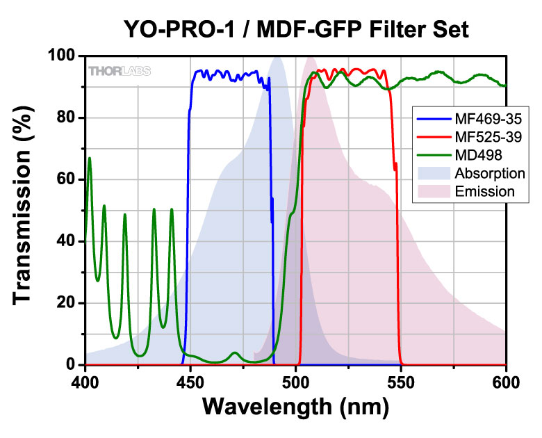
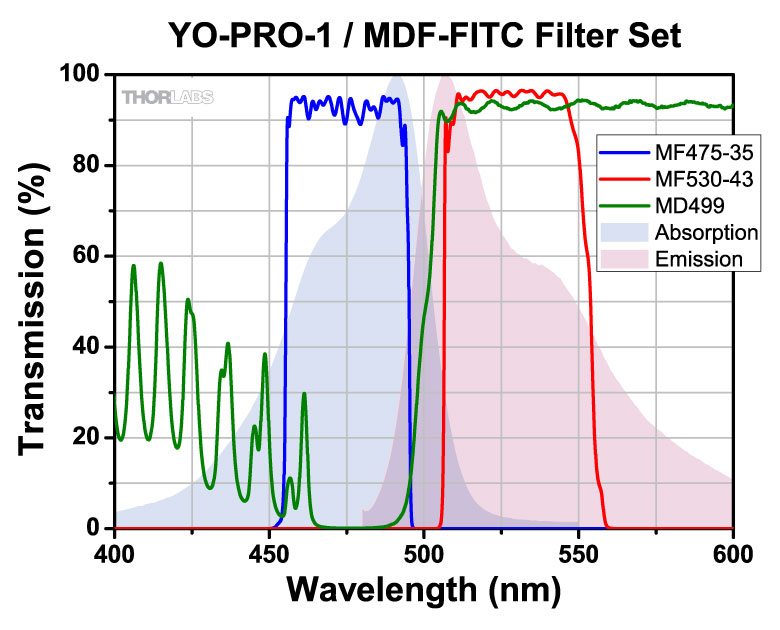
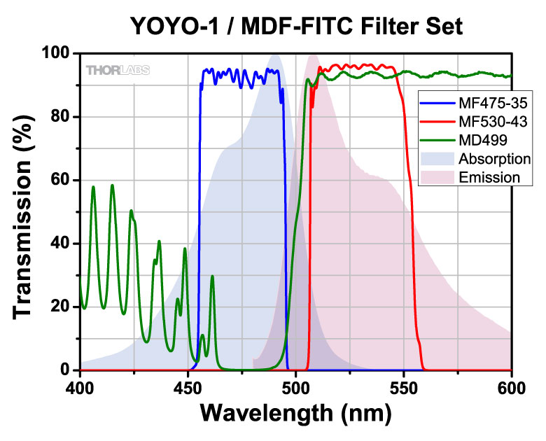
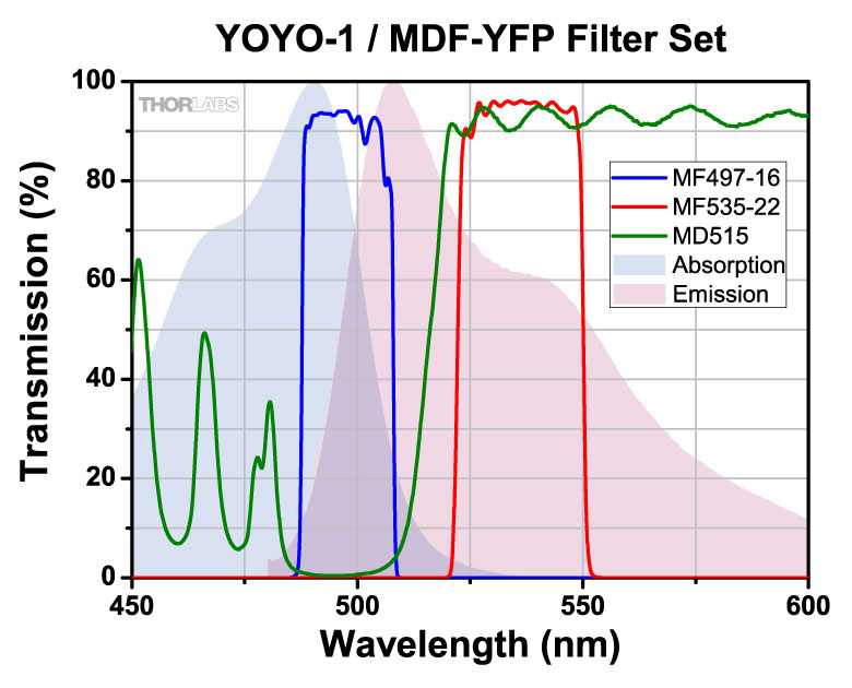
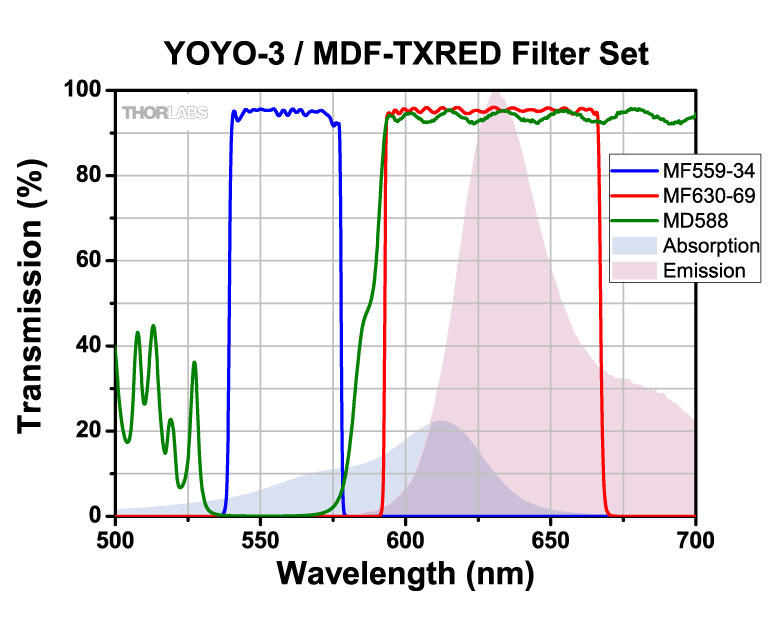
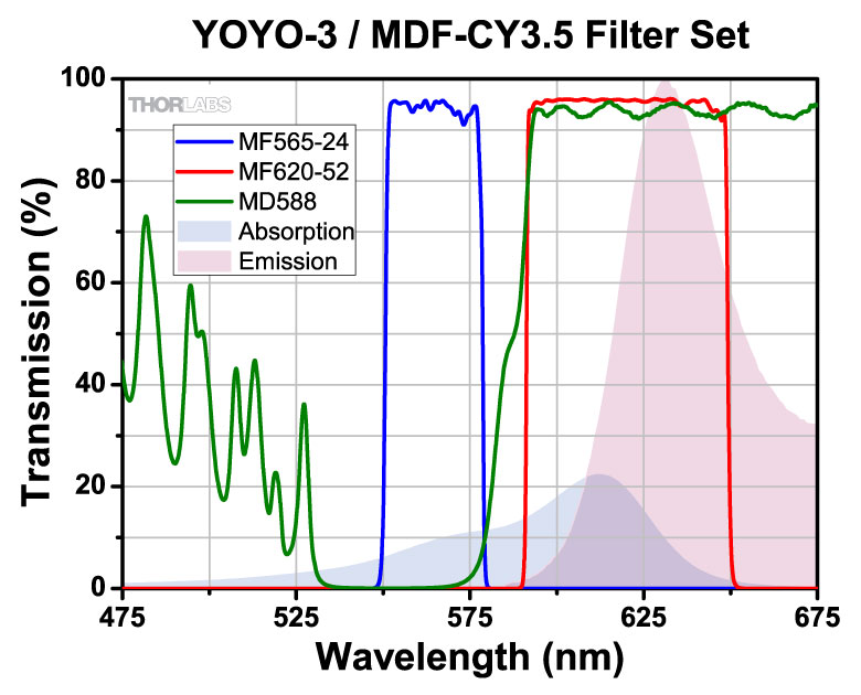
Fiber Collimator Selection Guide
Click on the collimator type or photo to view more information about each type of collimator.
| Type | Description | |
|---|---|---|
| Fixed FC, APC, or SMA Fiber Collimators | 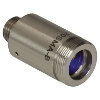 |
These fiber collimation packages are pre-aligned to collimate light from an FC/PC-, FC/APC-, or SMA-terminated fiber. Each collimation package is factory aligned to provide diffraction-limited performance for wavelengths ranging from 405 nm to 4.55 µm. Although it is possible to use the collimator at detuned wavelengths, they will only perform optimally at the design wavelength due to chromatic aberration, which causes the effective focal length of the aspheric lens to have a wavelength dependence. |
| Air-Spaced Doublet, Large Beam Collimators | 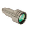 |
For large beam diameters (Ø5.3 - Ø8.5 mm), Thorlabs offers FC/APC, FC/PC, and SMA air-spaced doublet collimators. These collimation packages are pre-aligned at the factory to collimate a laser beam propagating from the tip of an FC or SMA-terminated fiber and provide diffraction-limited performance at the design wavelength. |
| Triplet Collimators | 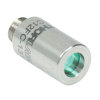 |
Thorlabs' High Quality Triplet Fiber Collimation packages use air-spaced triplet lenses that offer superior beam quality performance when compared to aspheric lens collimators. The benefits of the low-aberration triplet design include an M2 term closer to 1 (Gaussian), less divergence, and less wavefront error. |
| Achromatic Collimators for Multimode Fiber | 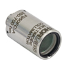 |
Thorlabs' High-NA Achromatic Collimators pair a meniscus lens with an achromatic doublet for high performance across the visible spectrum with low spherical aberration. Designed for use with high-NA multimode fiber, these collimators are ideal for Optogenetics and Fiber Photometry applications. |
| Reflective Collimators | 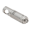 |
Thorlabs' metallic-coated Reflective Collimators are based on a 90° off-axis parabolic mirror. Mirrors, unlike lenses, have a focal length that remains constant over a broad wavelength range. Due to this intrinsic property, a parabolic mirror collimator does not need to be adjusted to accommodate various wavelengths of light, making them ideal for use with polychromatic light. Our reflective collimators are ideal for collimating single mode fiber but are not recommended for coupling into single mode fiber. We also offer a compact version of the protected-silver-coated reflective collimators that is directly compatible with our 16 mm cage system. |
| FiberPorts | 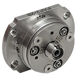 |
These compact, ultra-stable FiberPort micropositioners provide an easy-to-use, stable platform for coupling light into and out of FC/PC, FC/APC, or SMA terminated optical fibers. It can be used with single mode, multimode, or PM fibers and can be mounted onto a post, stage, platform, or laser. The built-in aspheric or achromatic lens is available with five different AR coatings and has five degrees of alignment adjustment (3 translational and 2 pitch). The compact size and long-term alignment stability make the FiberPort an ideal solution for fiber coupling, collimation, or incorporation into OEM systems. |
| Adjustable Fiber Collimators |  |
These collimators are designed to connect onto the end of an FC/PC, FC/APC, or SMA connector and contain an AR-coated aspheric lens. The distance between the aspheric lens and the tip of the fiber can be adjusted to compensate for focal length changes or to recollimate the beam at the wavelength and distance of interest. |
| Achromatic Fiber Collimators with Adjustable Focus | 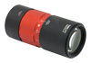 |
Thorlabs' Achromatic Fiber Collimators with Adjustable Focus are designed with an effective focal length (EFL) of 20 mm, 40 mm, or 80 mm, have optical elements broadband AR coated for one of three wavelength ranges, and are available with FC/PC, FC/APC, or SMA905 connectors. A four-element, air-spaced lens design produces superior beam quality (M2 close to 1) and less wavefront error when compared to aspheric lens collimators. These collimators can be used for free-space coupling into a fiber, collimation of output from a fiber, or in pairs for collimator-to-collimator coupling over long distances, which allows the beam to be manipulated prior to entering the second collimator. |
| Zoom Fiber Collimators | 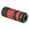 |
These collimators provide a variable focal length between 6 and 18 mm, while maintaining the collimation of the beam. As a result, the size of the beam can be changed without altering the collimation. This universal device saves time previously spent searching for the best suited fixed fiber collimator and has a very broad range of applications. They are offered with FC/PC, FC/APC, or SMA905 connectors with three different antireflection wavelength ranges to choose from. |
| Single Mode Pigtailed Collimators | 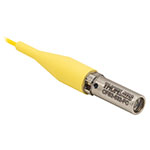 |
Our single mode pigtailed collimators come with one meter of fiber, consist of an AR-coated aspheric lens pre-aligned with respect to a fiber, and are collimated at one of eight wavelengths: 532 nm, 633 nm, 780 nm, 850 nm, 1030 nm, 1064 nm, 1310 nm, or 1550 nm. Although it is possible to use the collimator at any wavelength within the coating range, the coupling loss will increase as the wavelength is detuned from the design wavelength. |
| Polarization Maintaining Pigtailed Collimators | 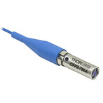 |
Our polarization maintaining pigtailed collimators come with one meter of fiber, consist of an AR-coated aspheric lens pre-aligned with respect to a fiber, and are collimated at one of six wavelengths: 532 nm, 830 nm, 1030 nm, 1064 nm, 1310 nm, or 1550 nm. Custom wavelengths and connectors are available as well. A line is engraved along the outside of the housing that is parallel to the slow axis. As such, it can be used as a reference when polarized light is launched accordingly. Although it is possible to use the collimator at any wavelength within the coating range, the coupling loss will increase as the wavelength is detuned from the design wavelength. |
| GRIN Fiber Collimators | 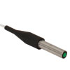 |
Thorlabs offers gradient index (GRIN) fiber collimators that are aligned at a variety of wavelengths from 630 to 1550 nm and have either FC terminated, APC terminated, or unterminated fibers. Our GRIN collimators feature a Ø1.8 mm clear aperture, are AR-coated to ensure low back reflection into the fiber, and are coupled to standard single mode or graded-index multimode fibers. |
| GRIN Lenses |  |
These graded-index (GRIN) lenses are AR coated for applications at 630, 830, 1060, 1300, or 1560 nm that require light to propagate through one fiber, then through a free-space optical system, and finally back into another fiber. They are also useful for coupling light from laser diodes into fibers, coupling the output of a fiber into a detector, or collimating laser light. Our GRIN lenses are designed to be used with our Pigtailed Glass Ferrules and GRIN/Ferrule sleeves. |
| Posted Comments: | |
PG Yu
(posted 2023-02-07 15:45:29.777) Request for a quote on a completed system including optic fiber cube, LED drive (530nm), emission filter, fiber-coupler LED, bandwidth detector. ksosnowski
(posted 2023-02-17 05:46:43.0) Hello, thanks for reaching out to Thorlabs. While system design is the responsibility of the user, we are happy to help with any questions about compatibility and how our devices operate. For these type of inquiries we recommend contacting techsupport@thorlabs.com directly. I have reached out to discuss your application in further detail. |